Open HardwareAssembly Instructions
Guides for installation and assembly of the LulzBot line of products made by Aleph Objects, Inc.
Guides for installation and assembly of the LulzBot line of products made by Aleph Objects, Inc.
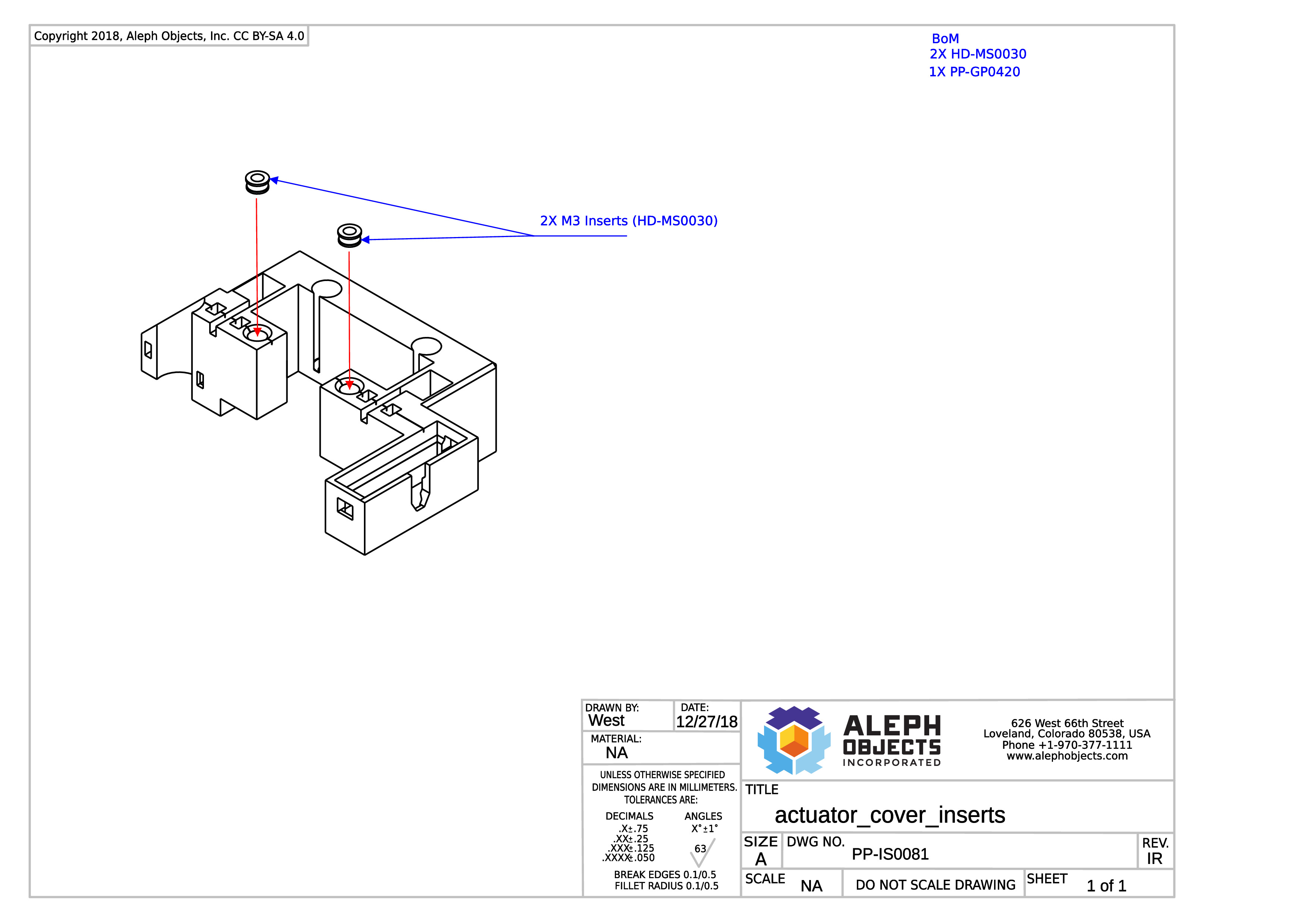
Thermal insert instructions for PP-IS0081.
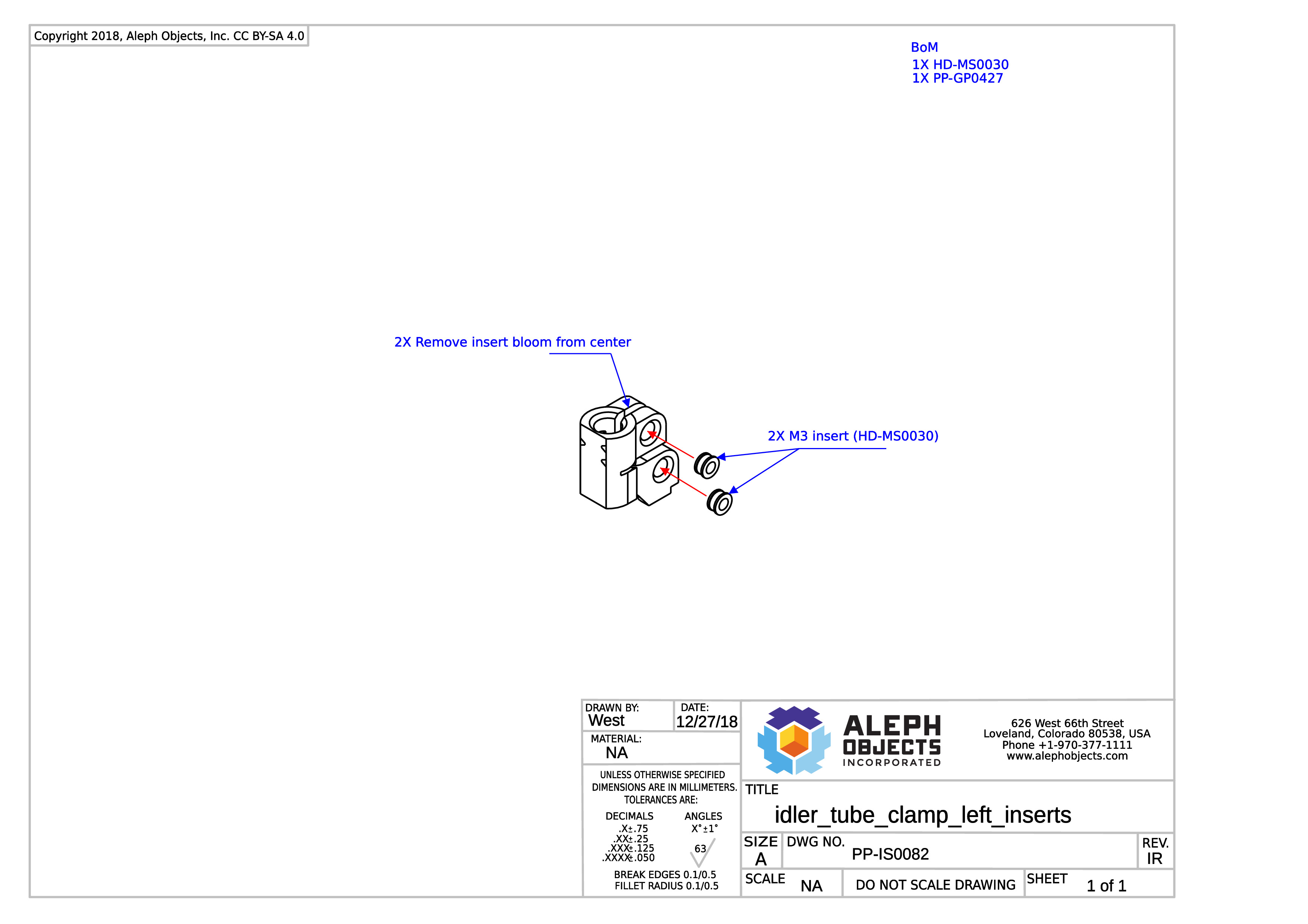
Thermal insert instructions for PP-IS0082.
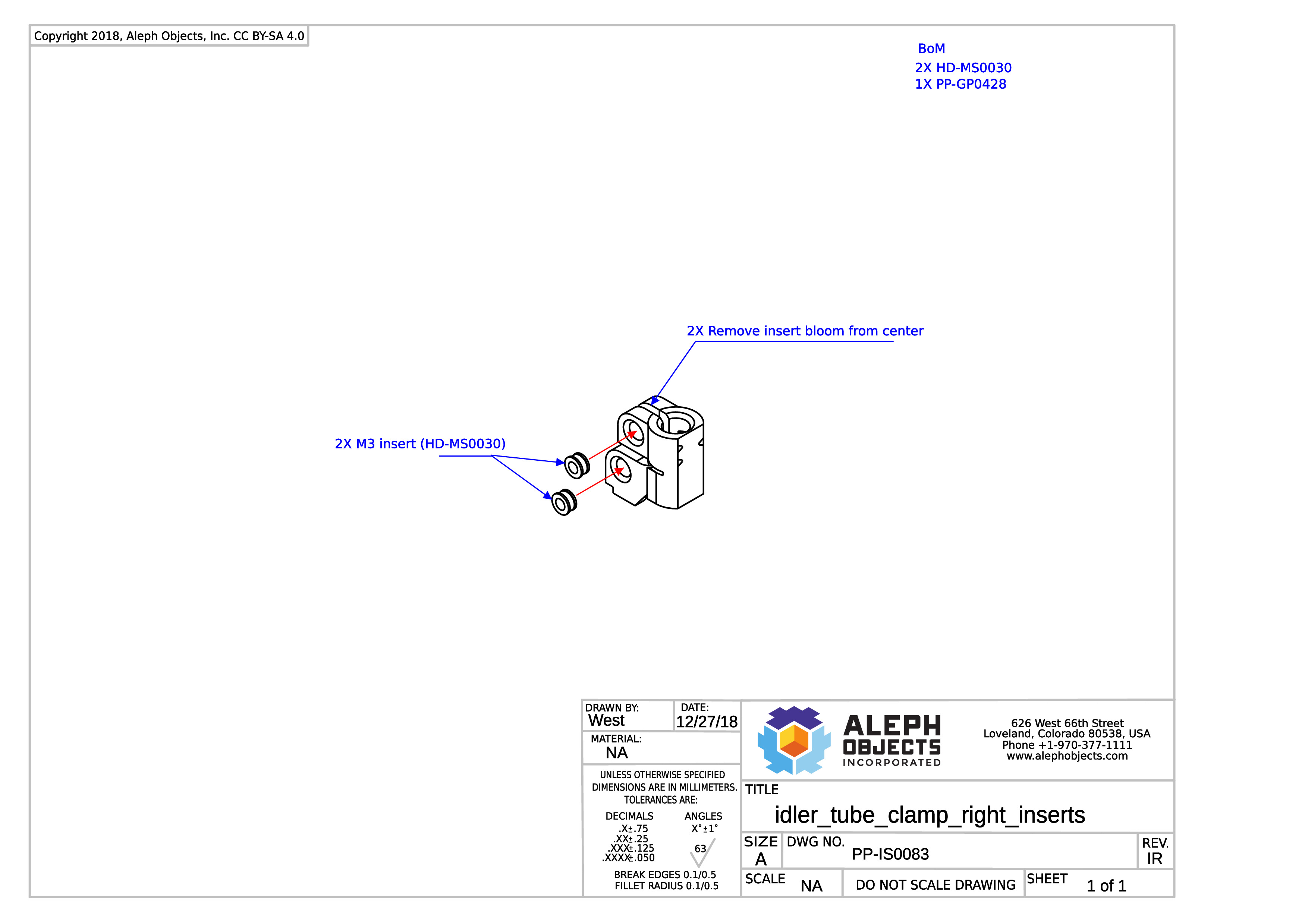
Thermal insert instructions for PP-IS0083.
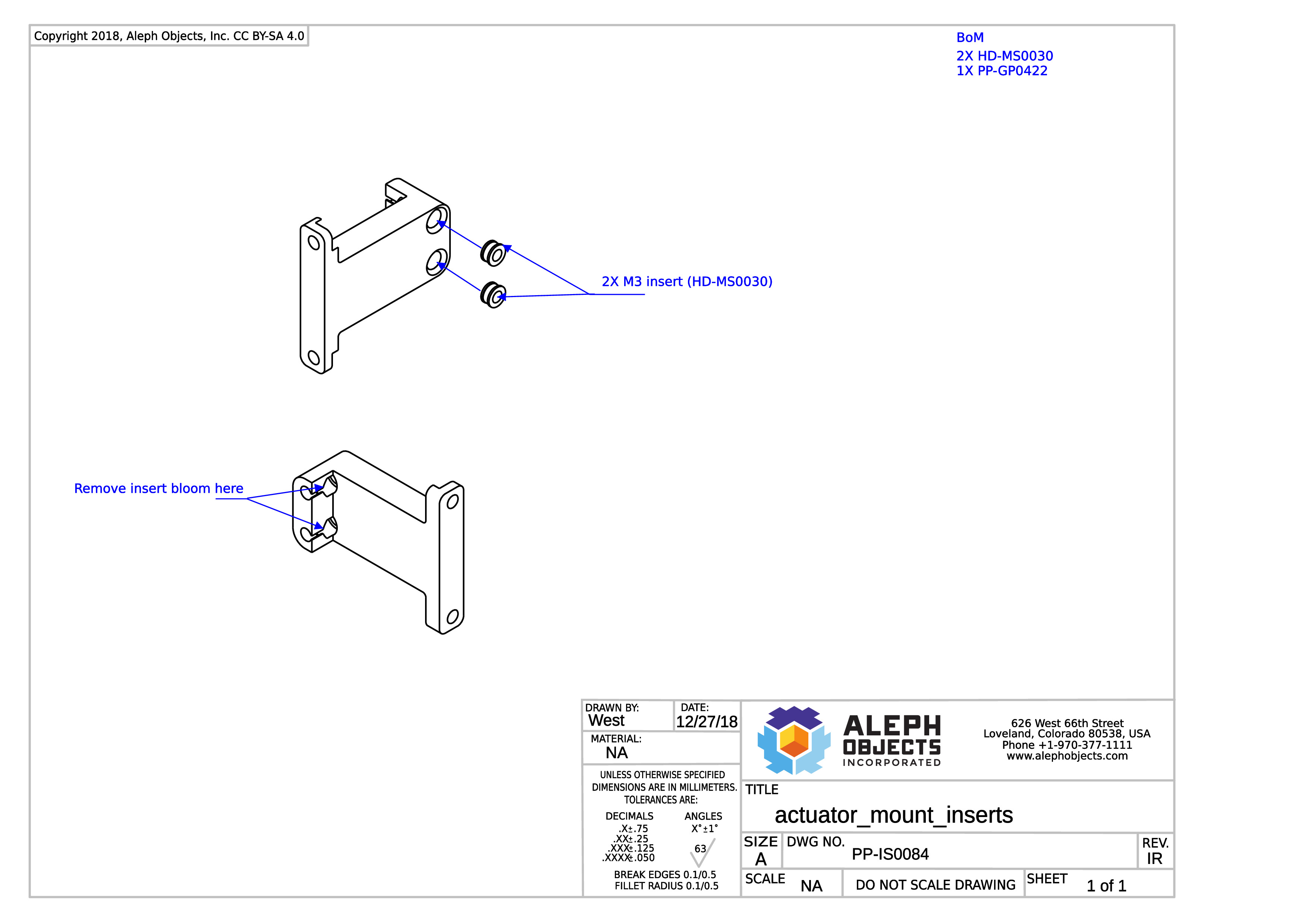
Thermal insert instructions for PP-IS0084.
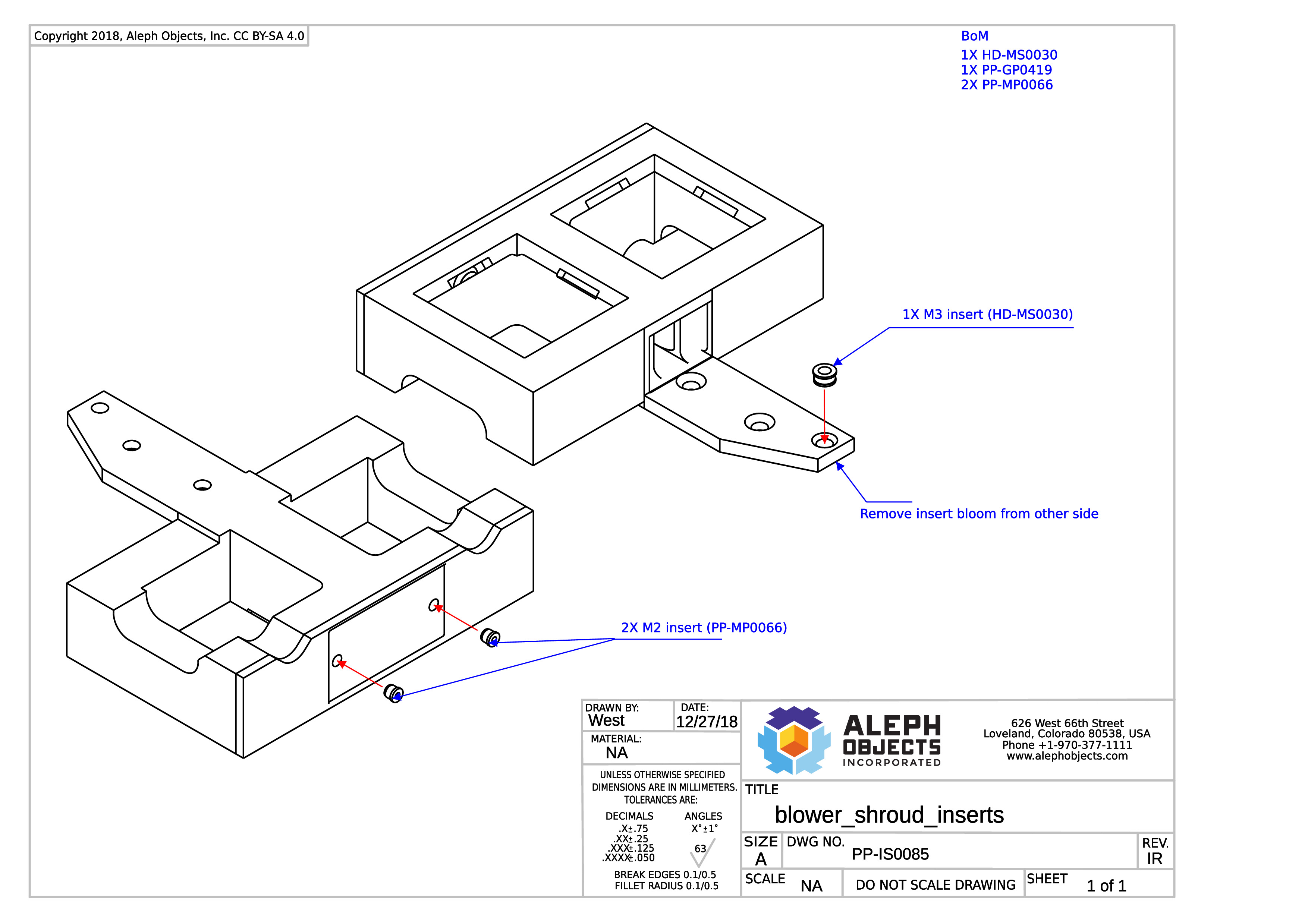
Thermal insert instructions for PP-IS0085.
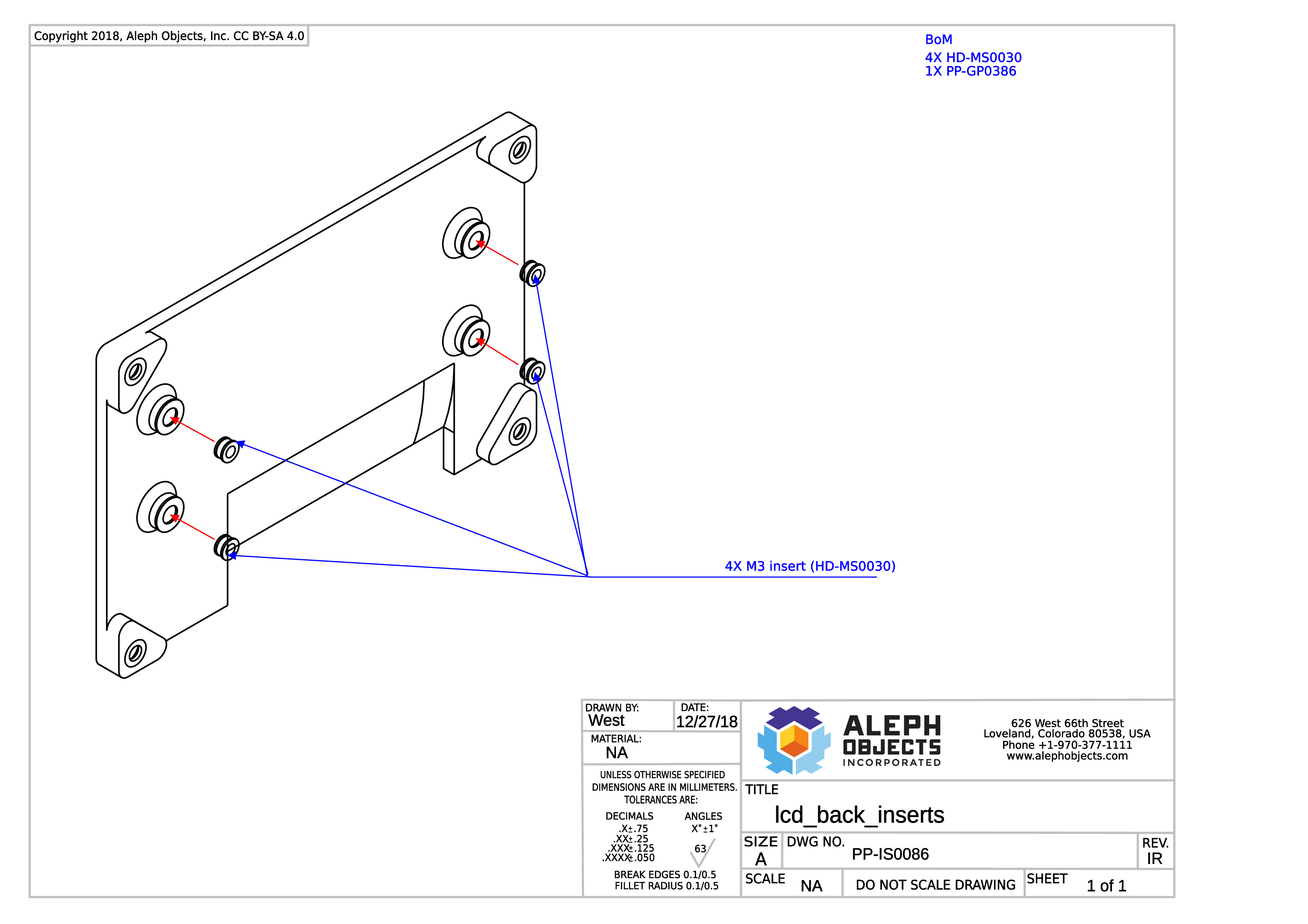
Thermal insert instructions for PP-IS0086.
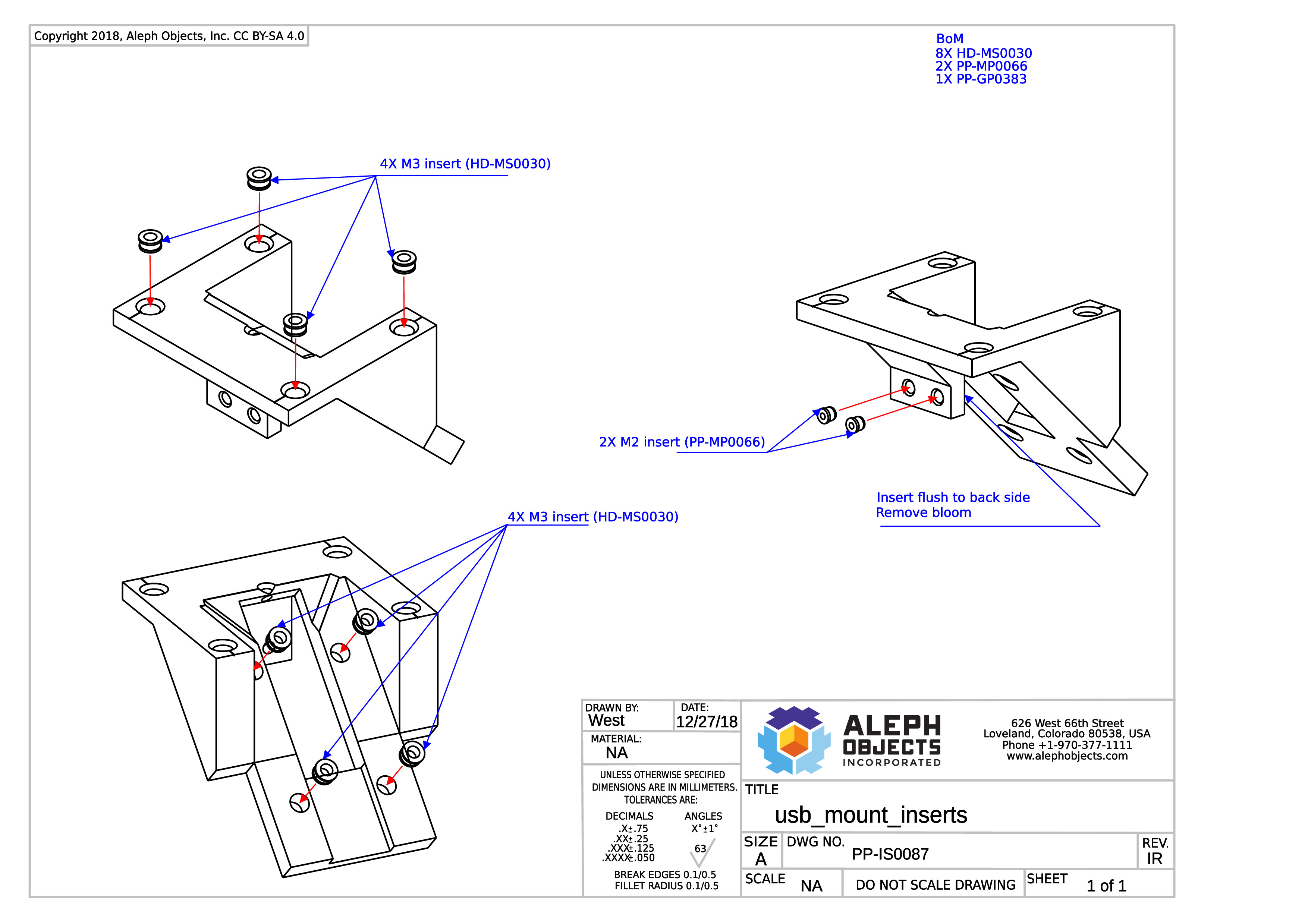
Thermal insert instructions for PP-IS0087.
General Sub-Assembly Instructions: Step 1, USB Reader Sub-Assembly
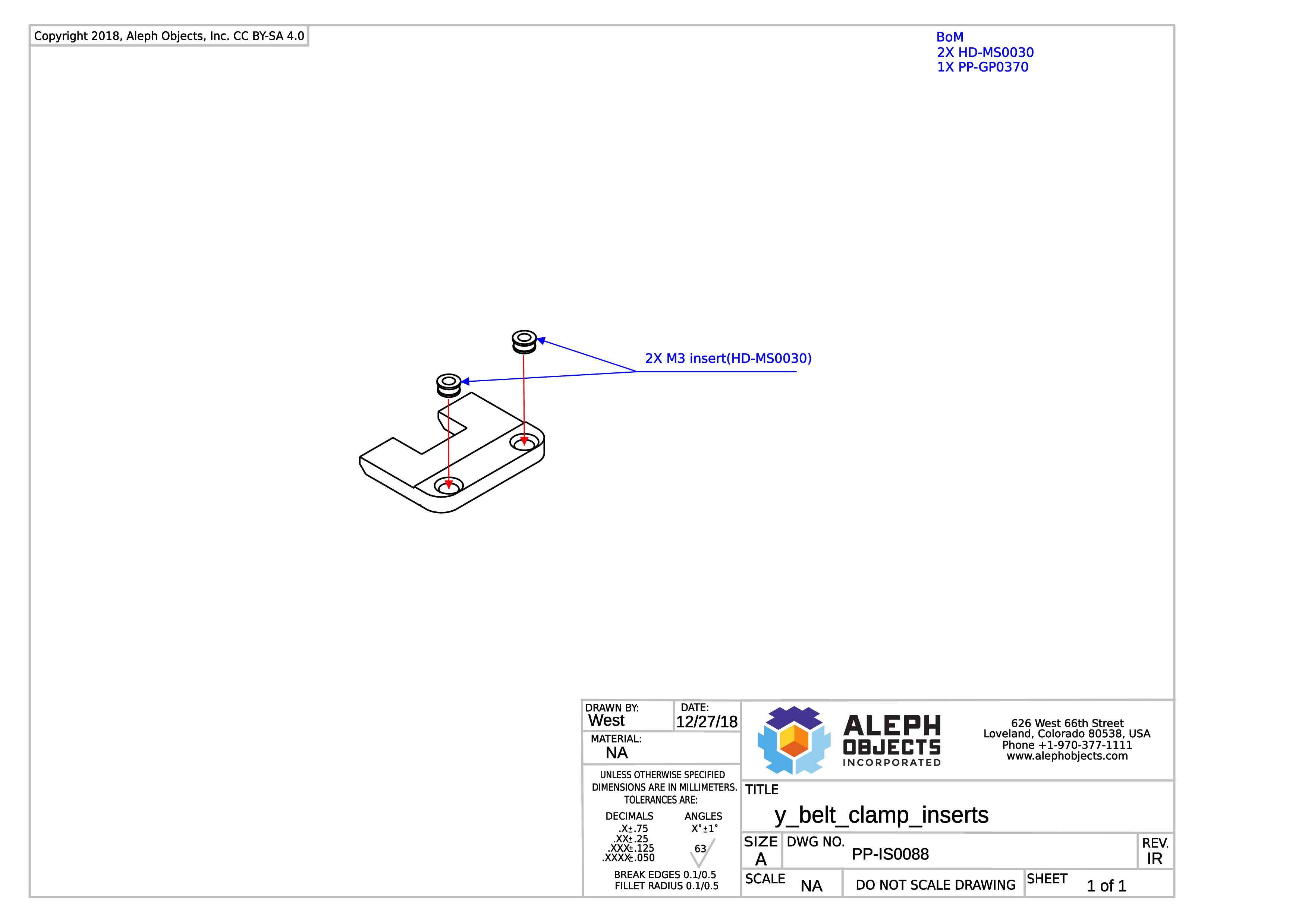
Thermal insert instructions for PP-IS0088.
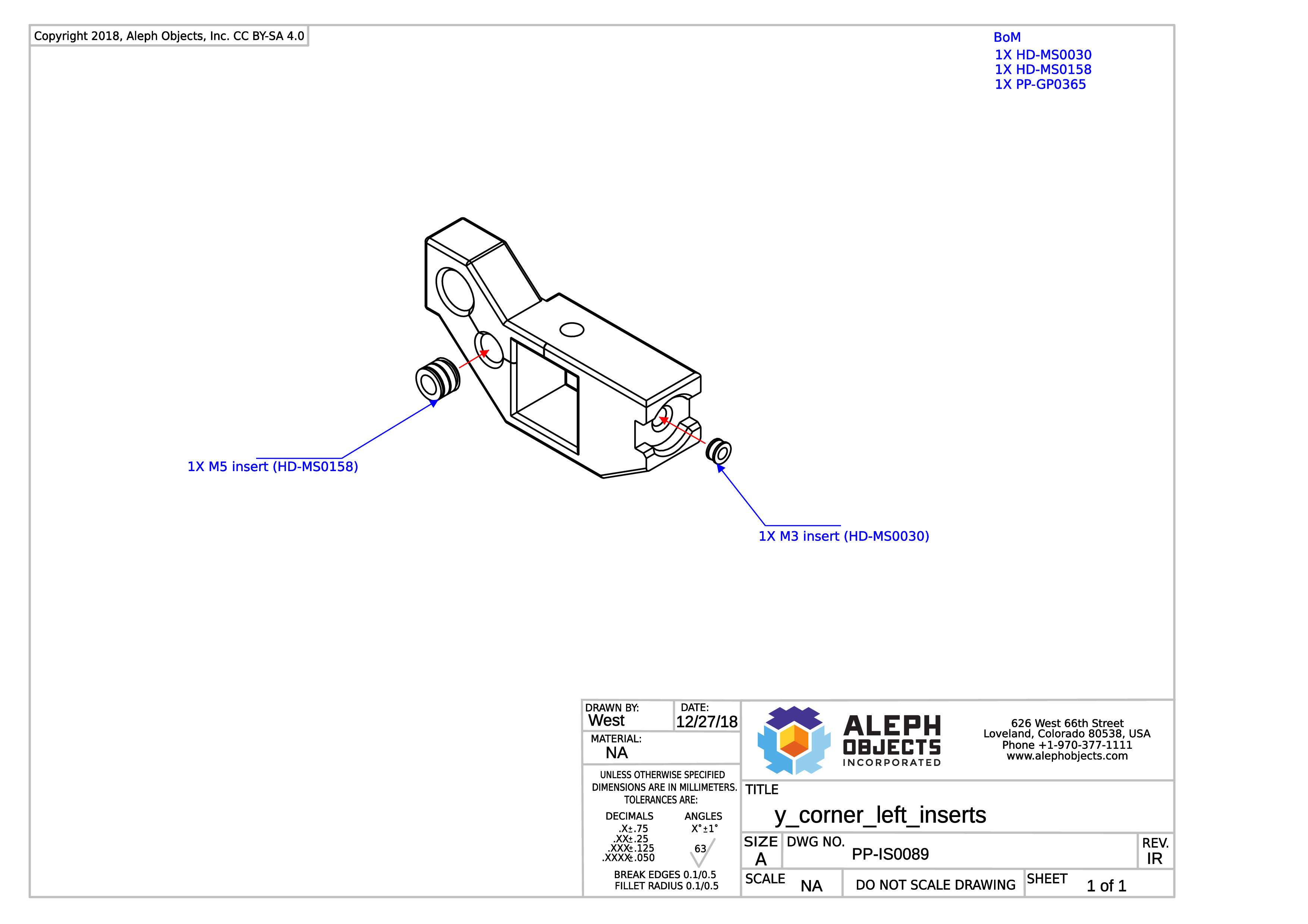
Thermal insert instructions PP-IS0089.
Note: Be sure to remove the bloom on the flat surface of the part, after installing the M5 insert.
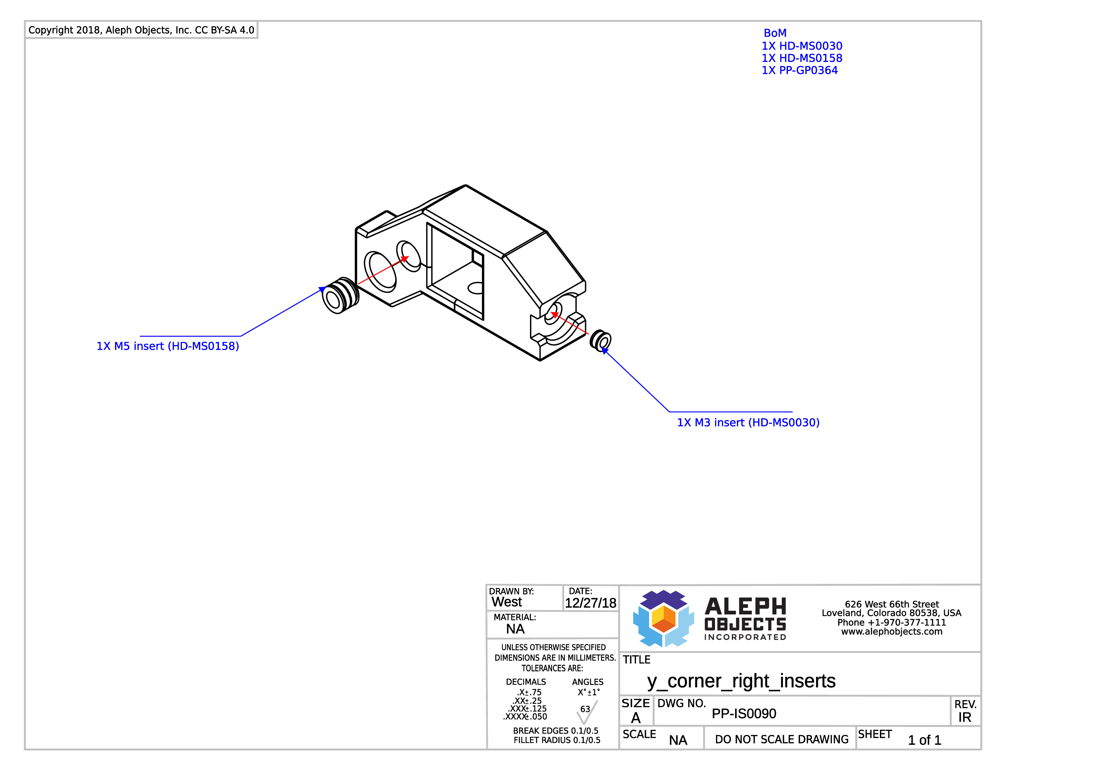
Thermal insert instructions for PP-IS0090.
Note: Be sure to remove the bloom on the flat surface of the part, after installing the M5 insert.
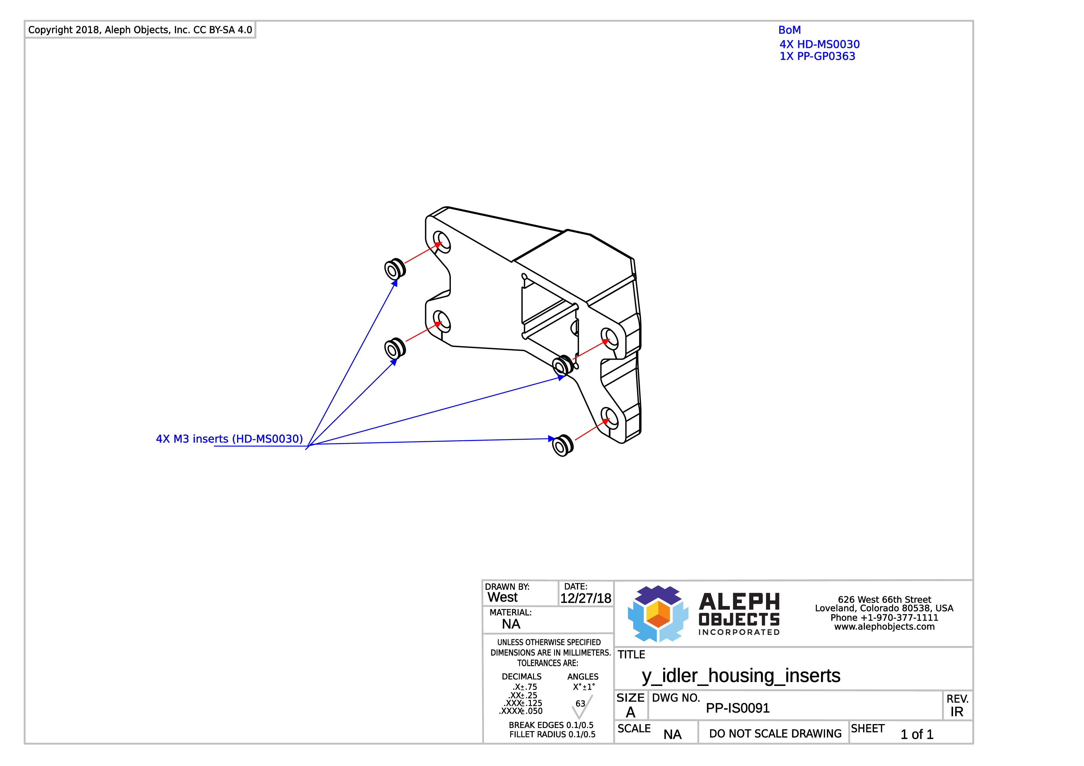
Thermal insert instructions for PP-IS0091.
Click the link below and go to step 11 for the mechanical assembly procedures.
General Sub-Assembly Instructions:Y-Idler Housing with Inserts
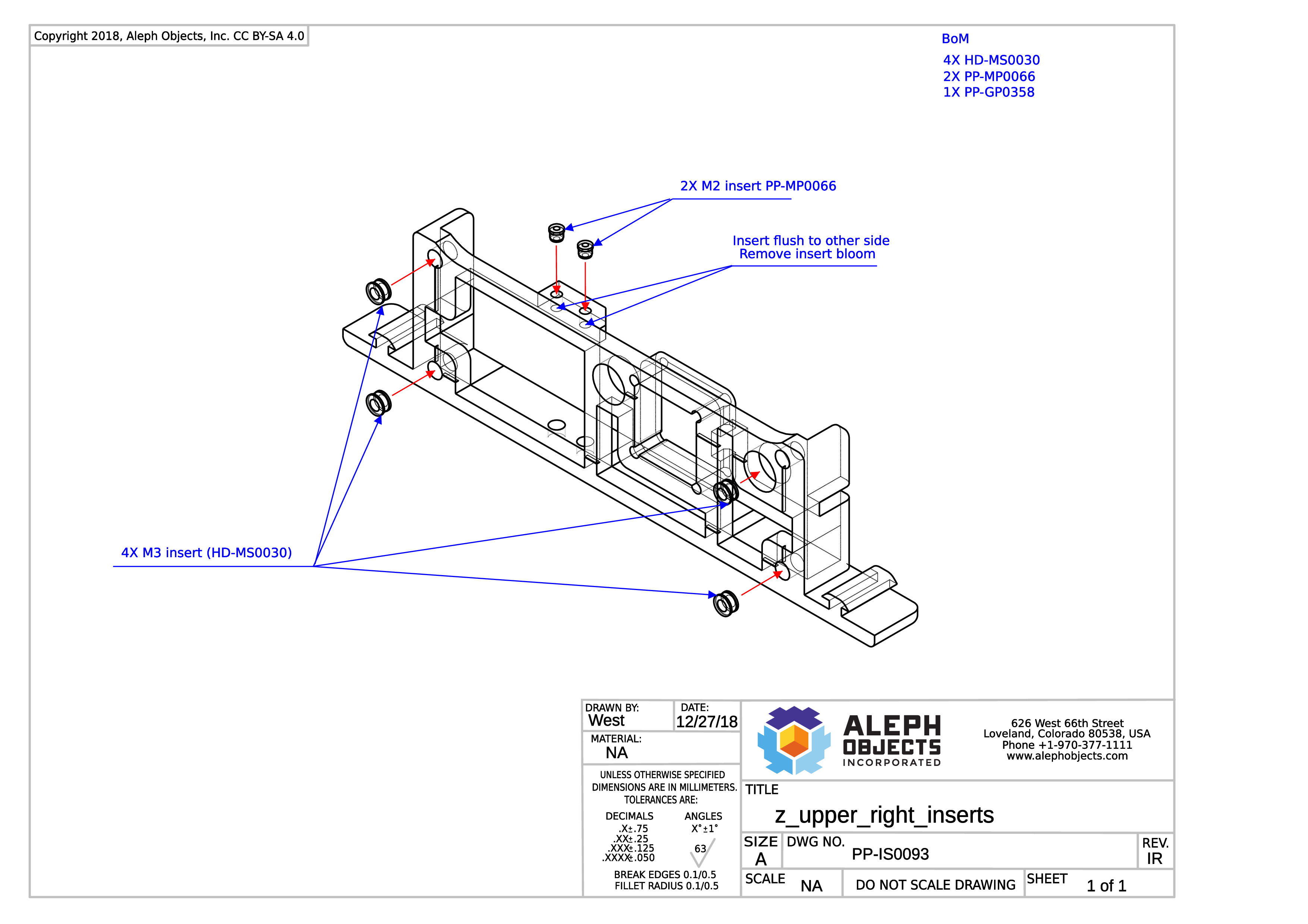
Thermal insert instructions for PP-IS0093.
Click the link below and go to step 7 for the mechanical assembly procedures.
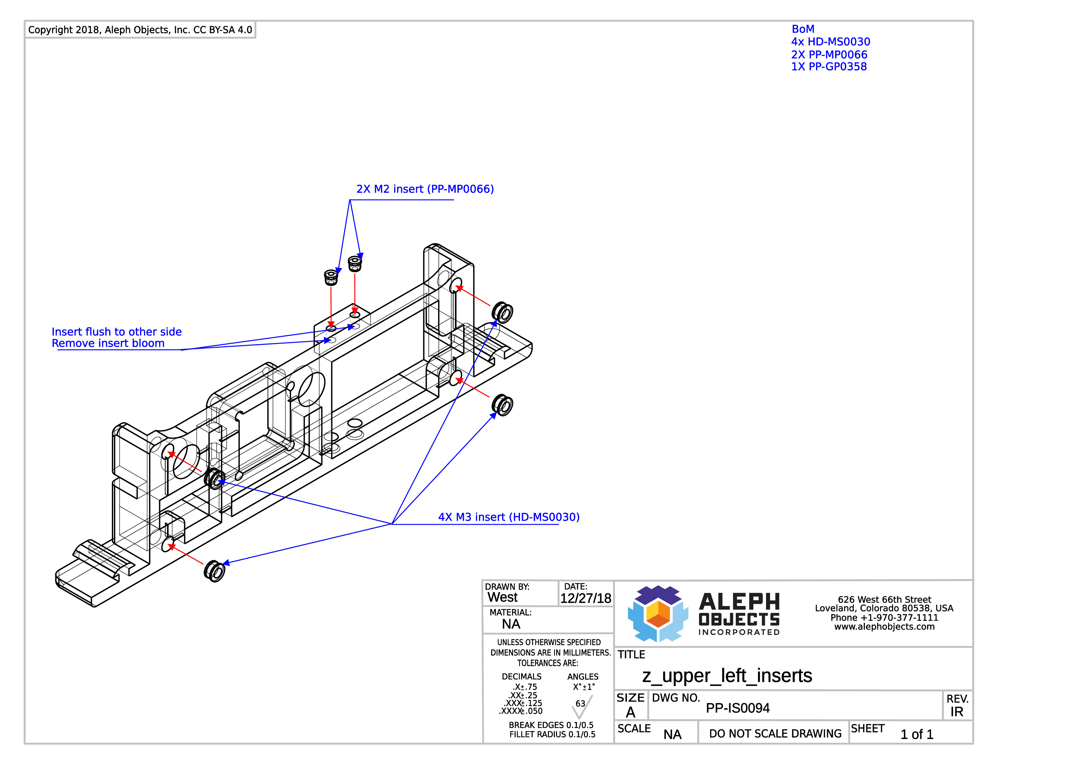
Thermal insert instructions for PP-IS0094.
Click the link below and go to step 8 for the mechanical assembly procedures.
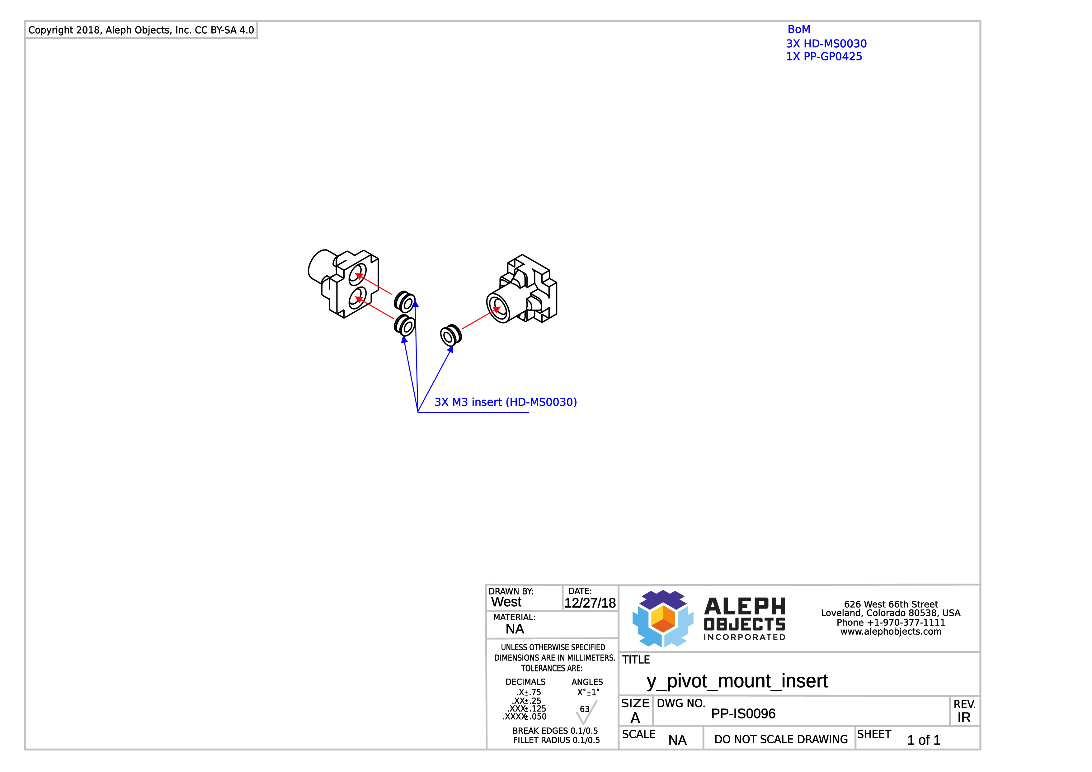
Thermal insert instructions for PP-IS0096.
Click the link below and go to step 9 for the mechanical assembly procedures.
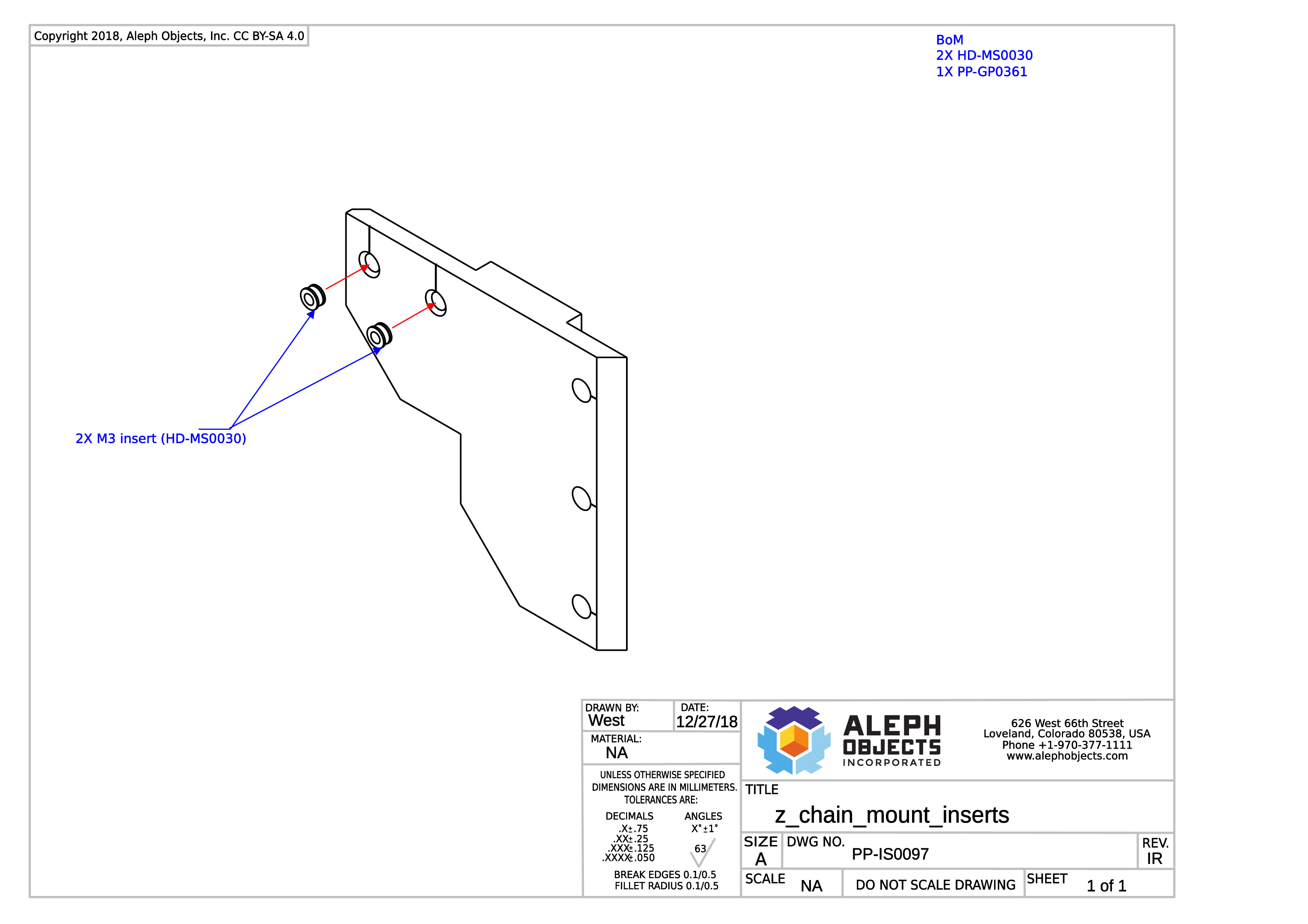
Thermal insert instructions for PP-IS0097.
Assembled during step 12 of the Frame Assembly procedures.
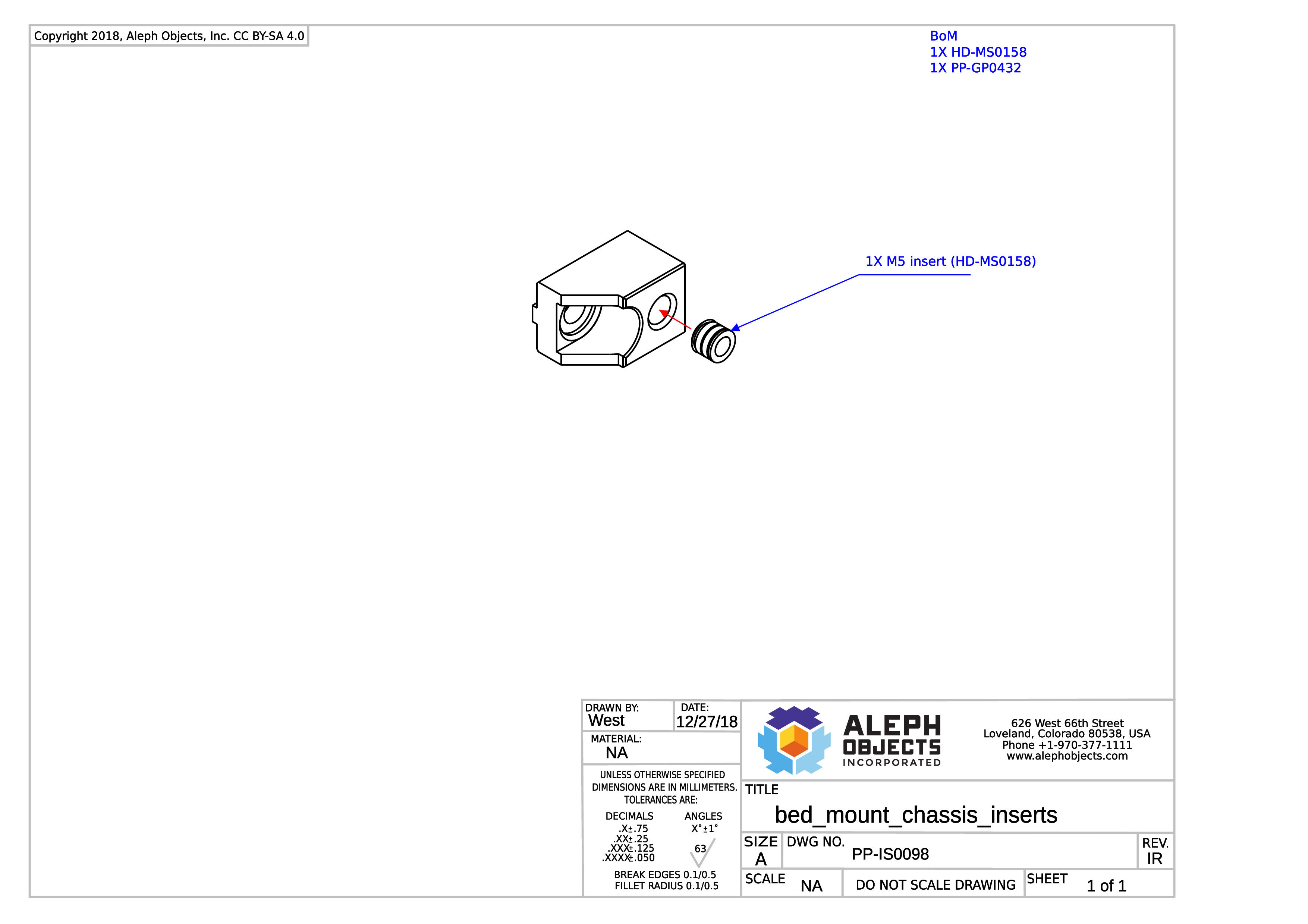
Thermal insert instructions for PP-IS0098.
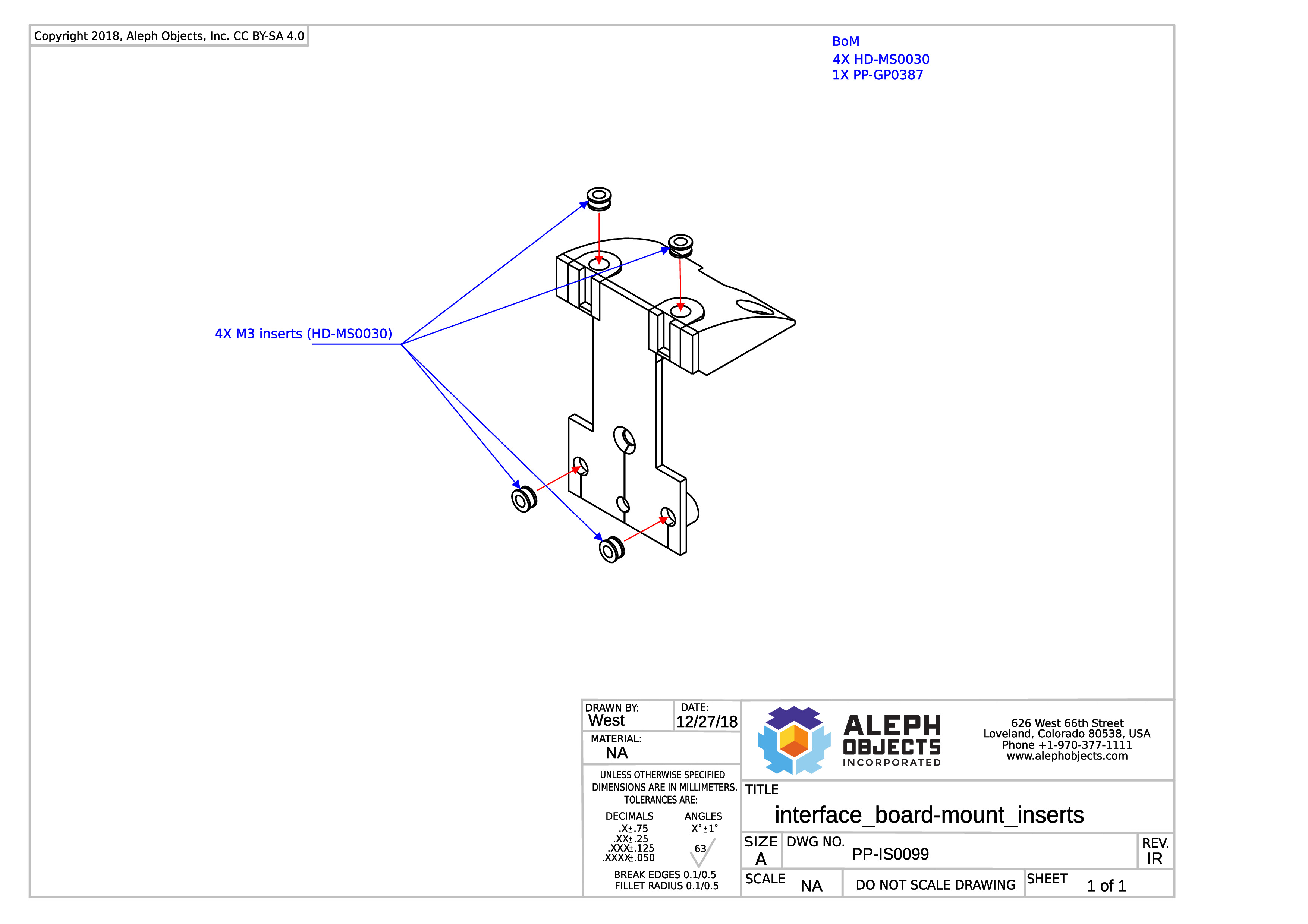
Thermal insert instructions for PP-IS0099.
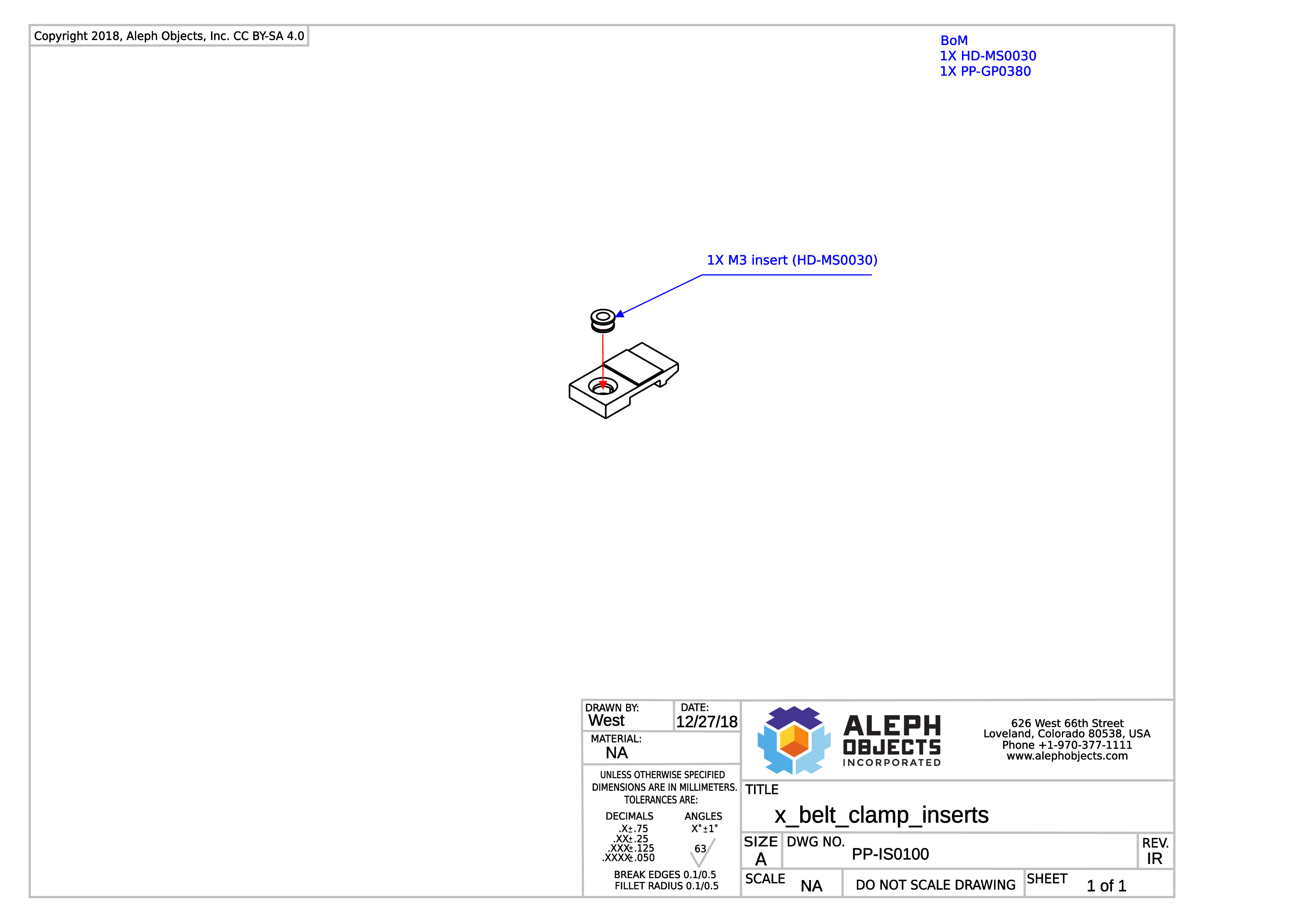
Thermal insert instructions for PP-IS0100.
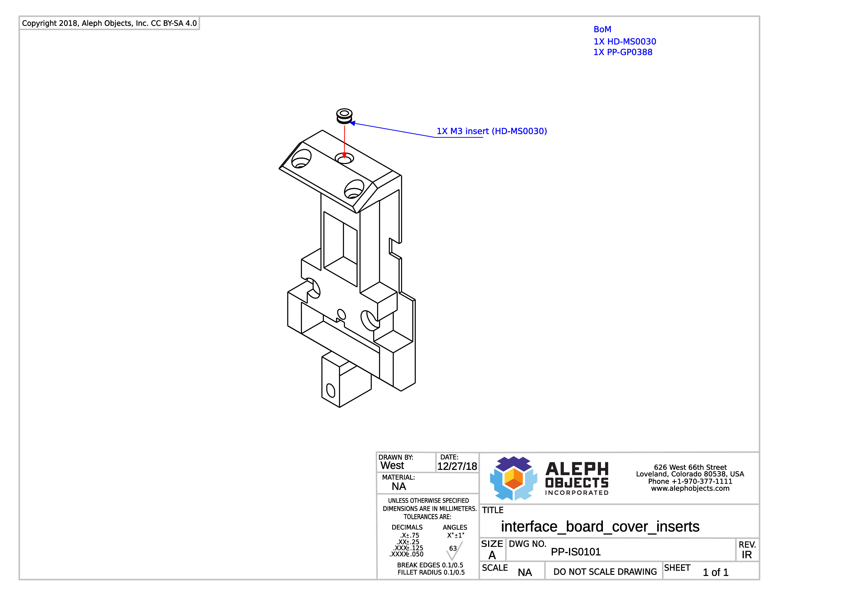
Thermal insert instructions PP-IS0101.
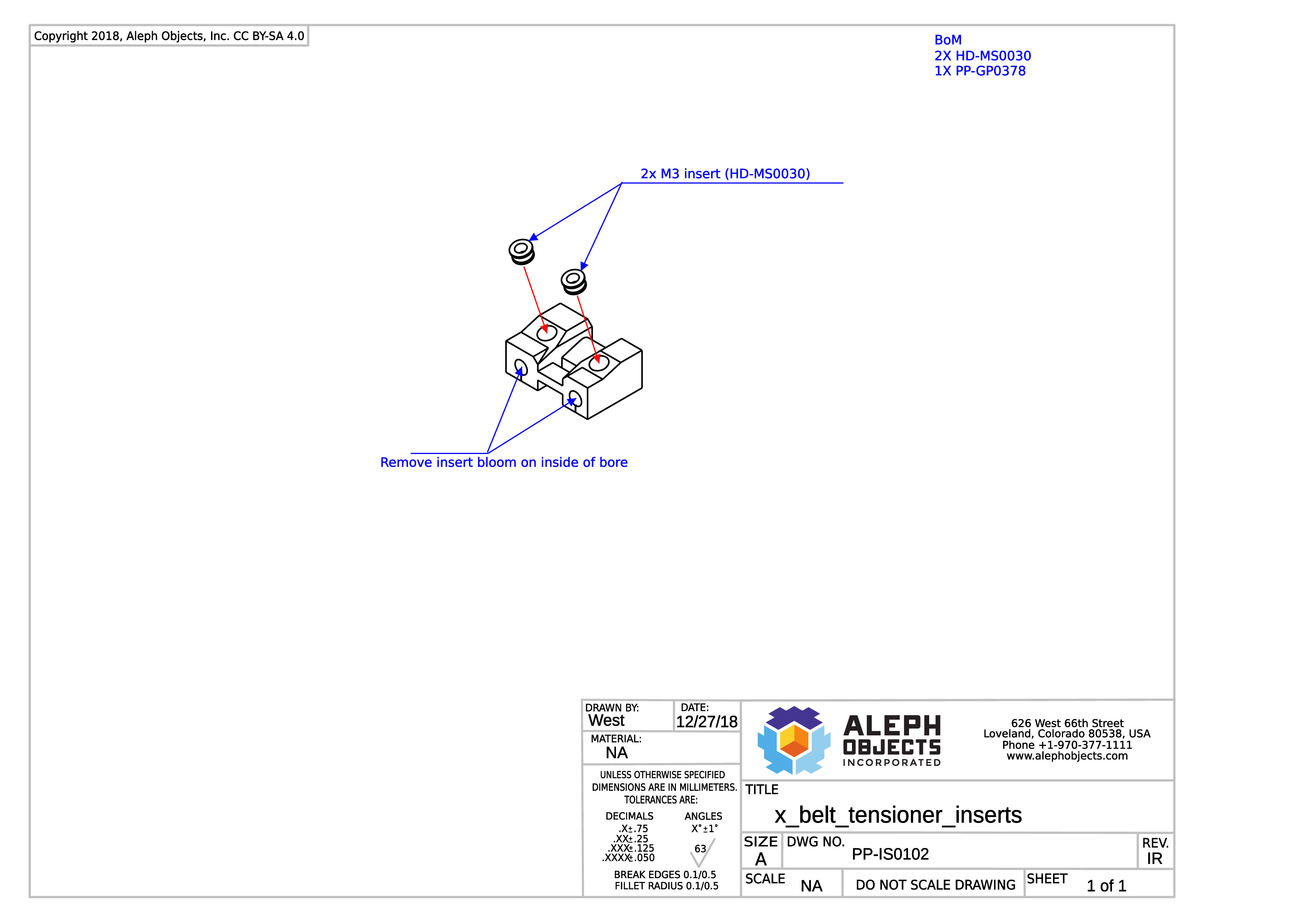
Thermal insert instructions for PP-IS0102
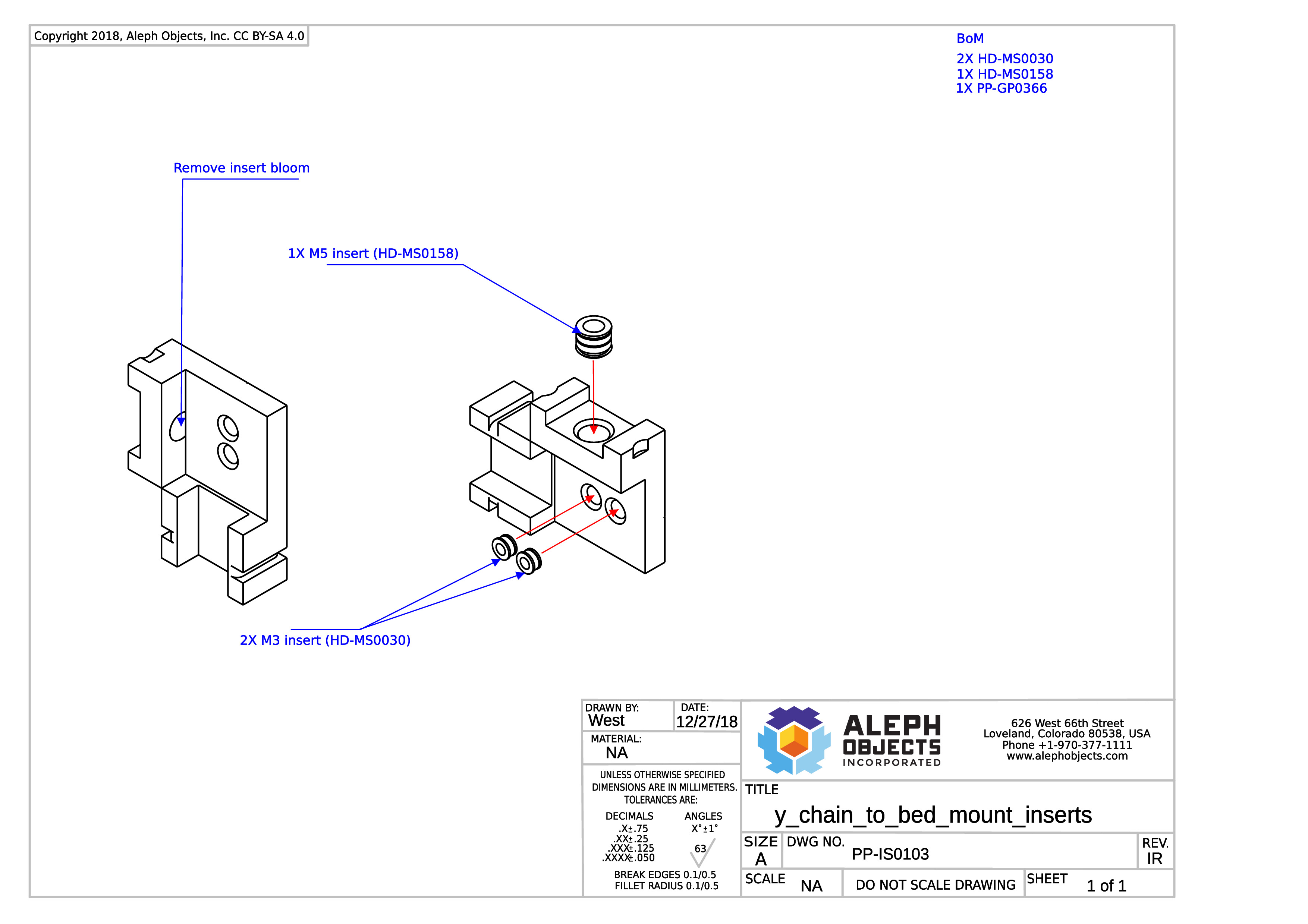
Thermal insert instructions for PP-IS0103.
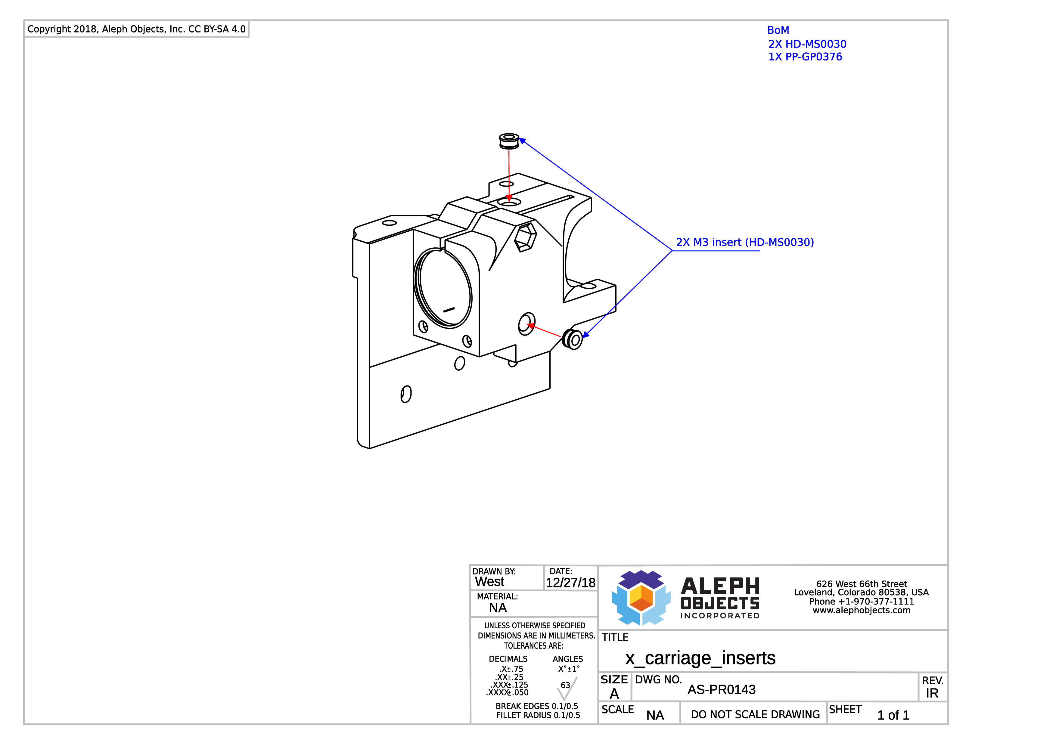
Thermal insert instructions for AS-PR0143.
General Sub-Assemblies: See step 4 for the mechanical assembly.
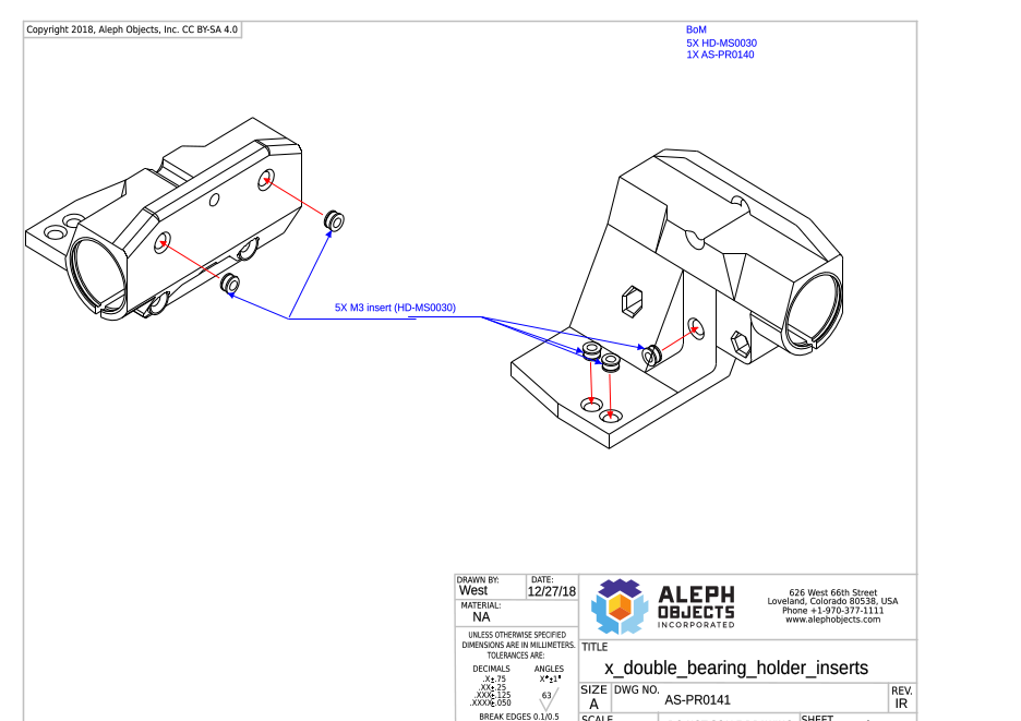
Thermal insert instructions for AS-PR0141.
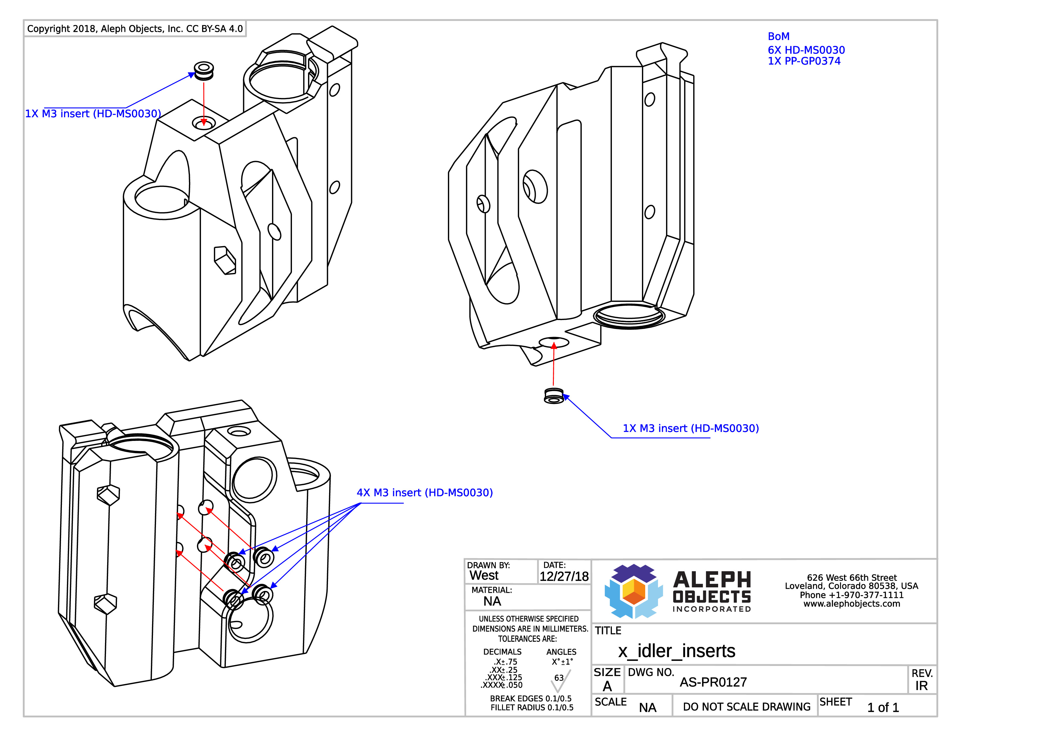
Thermal insert instructions for AS-PR0127.
Click the link below and go to step 3 for the mechanical assembly procedures.
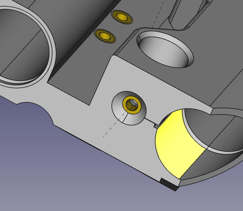
General Sub-Assembly Instructions: Assembling the X-End Idler
NOTE: ensure the insert is flush with the bottom of the chamfer
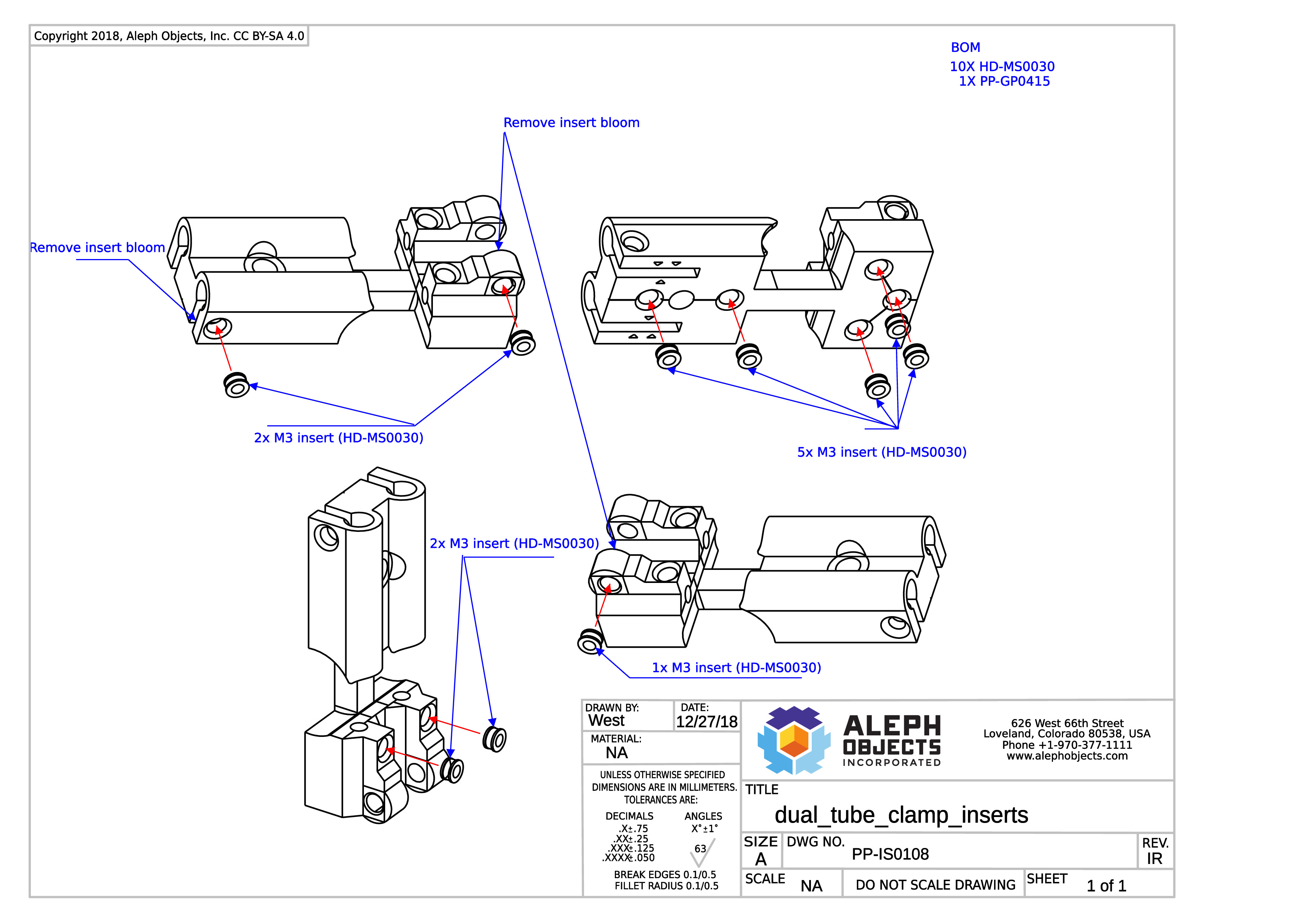
Thermal insert instructions for PP-IS0108.
Click the link below and go to step 2 for the mechanical assembly procedures.
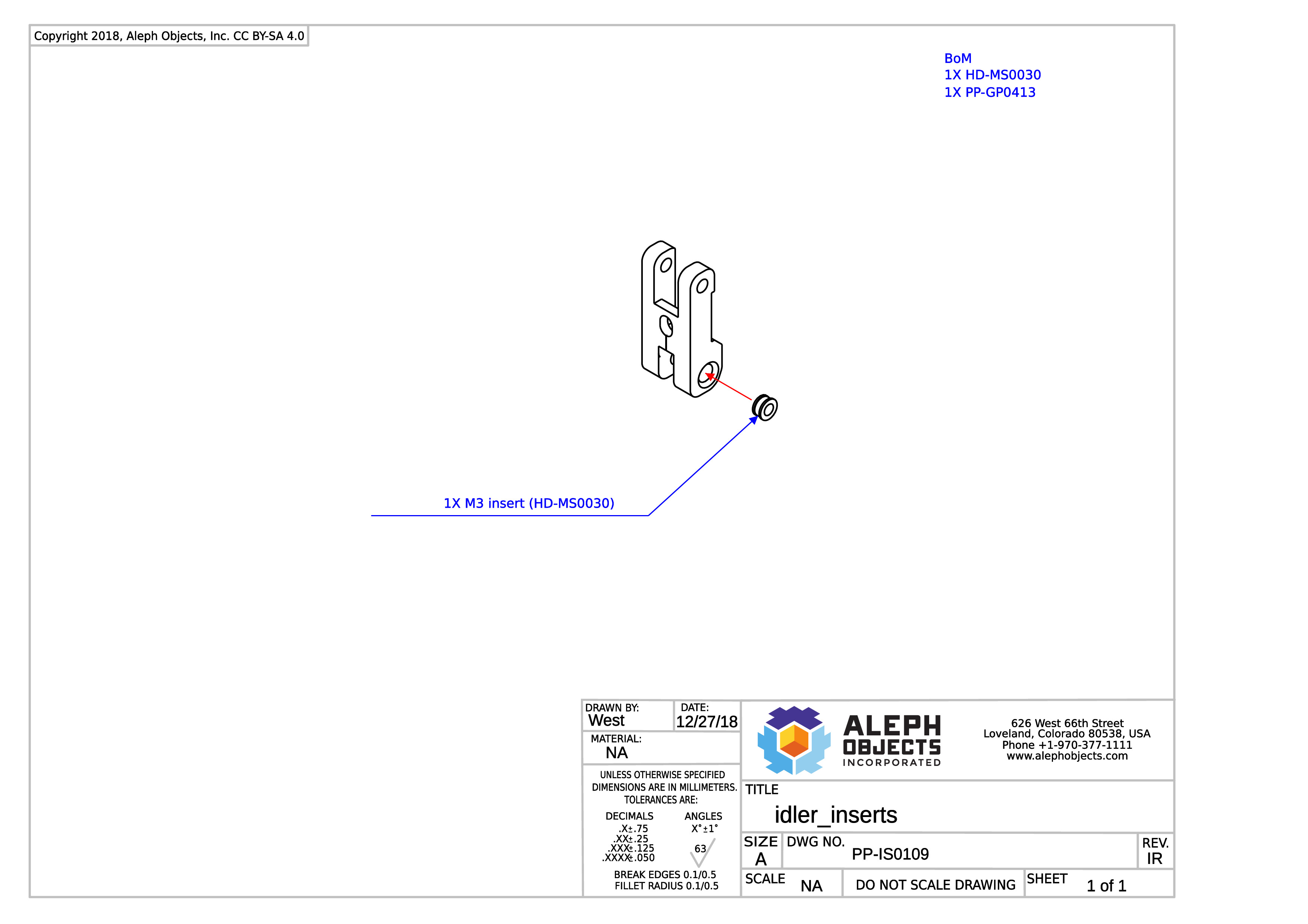
Thermal insert instructions for PP-IS0109.
Click the link below and go to step 6 for the mechanical assembly procedures.
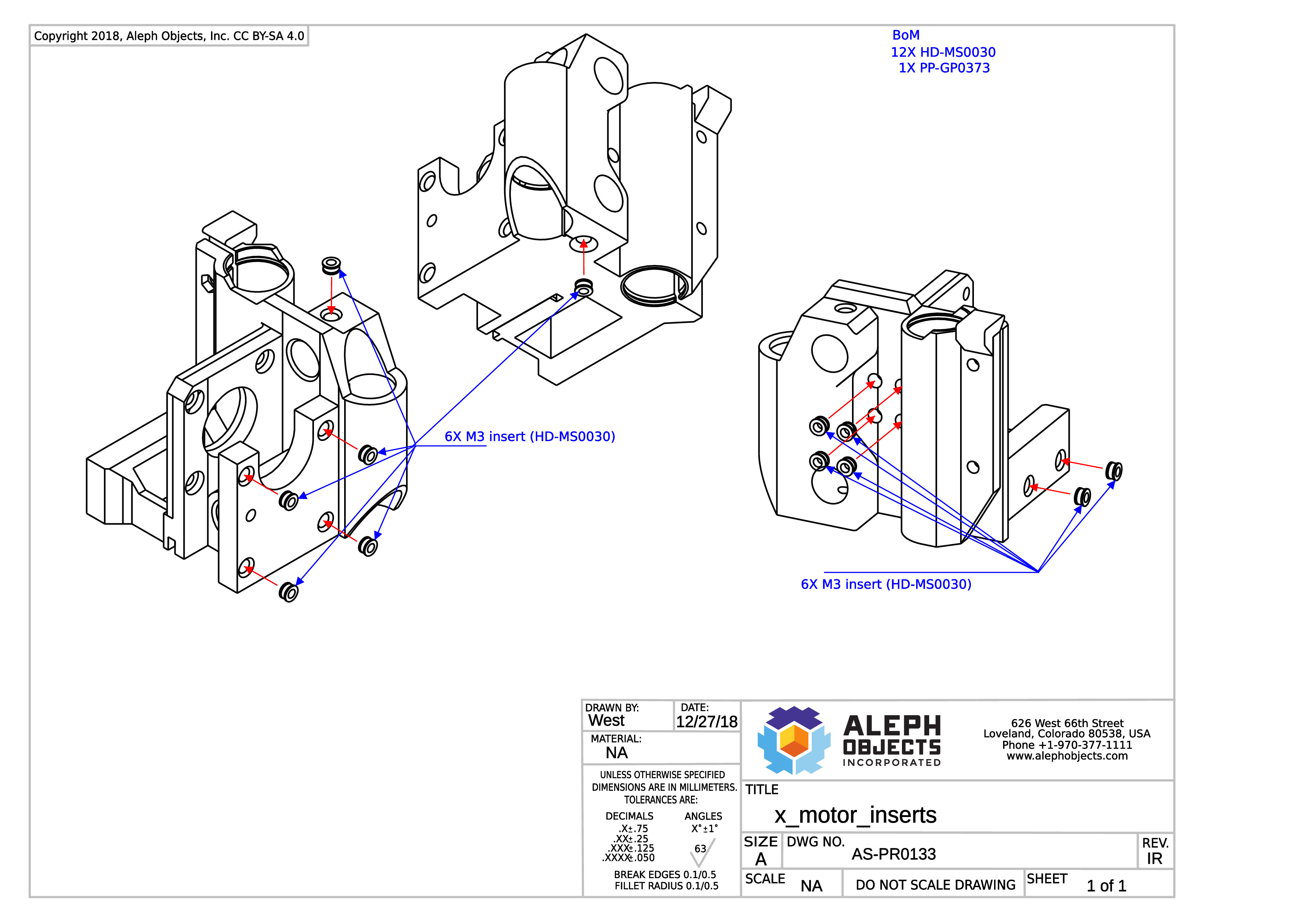
Thermal insert instructions for AS-PR0133.

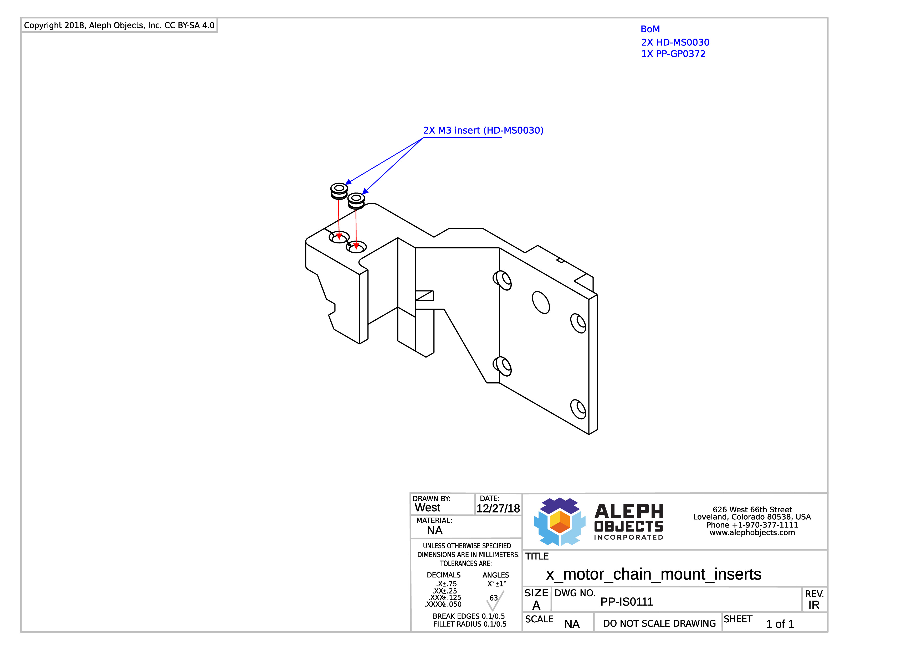
Thermal insert instructions for PP-IS0111.
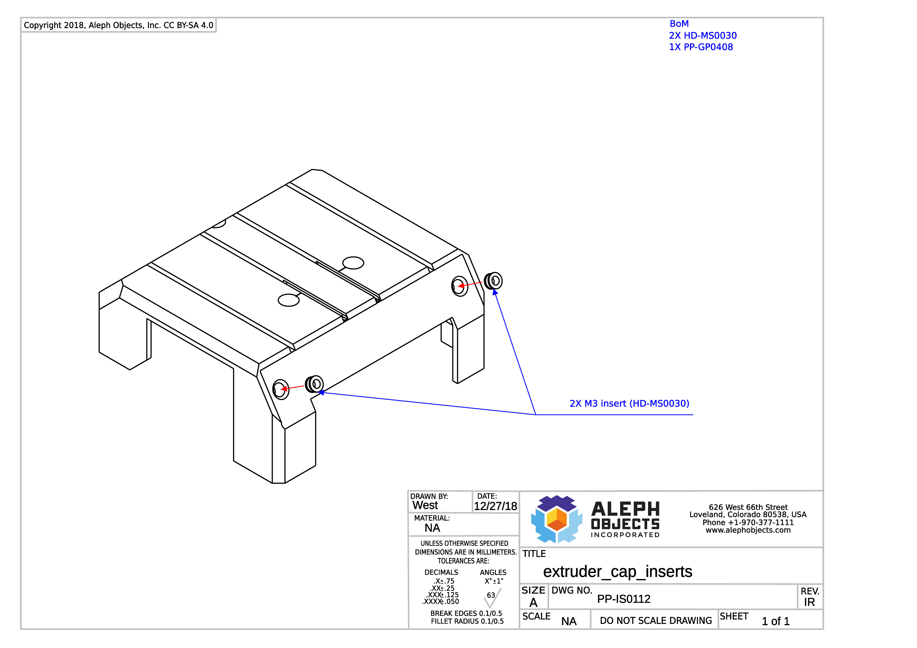
Thermal insert instructions for PP-IS0112.
Click this link, then scroll to example 3 for special insert instructions.
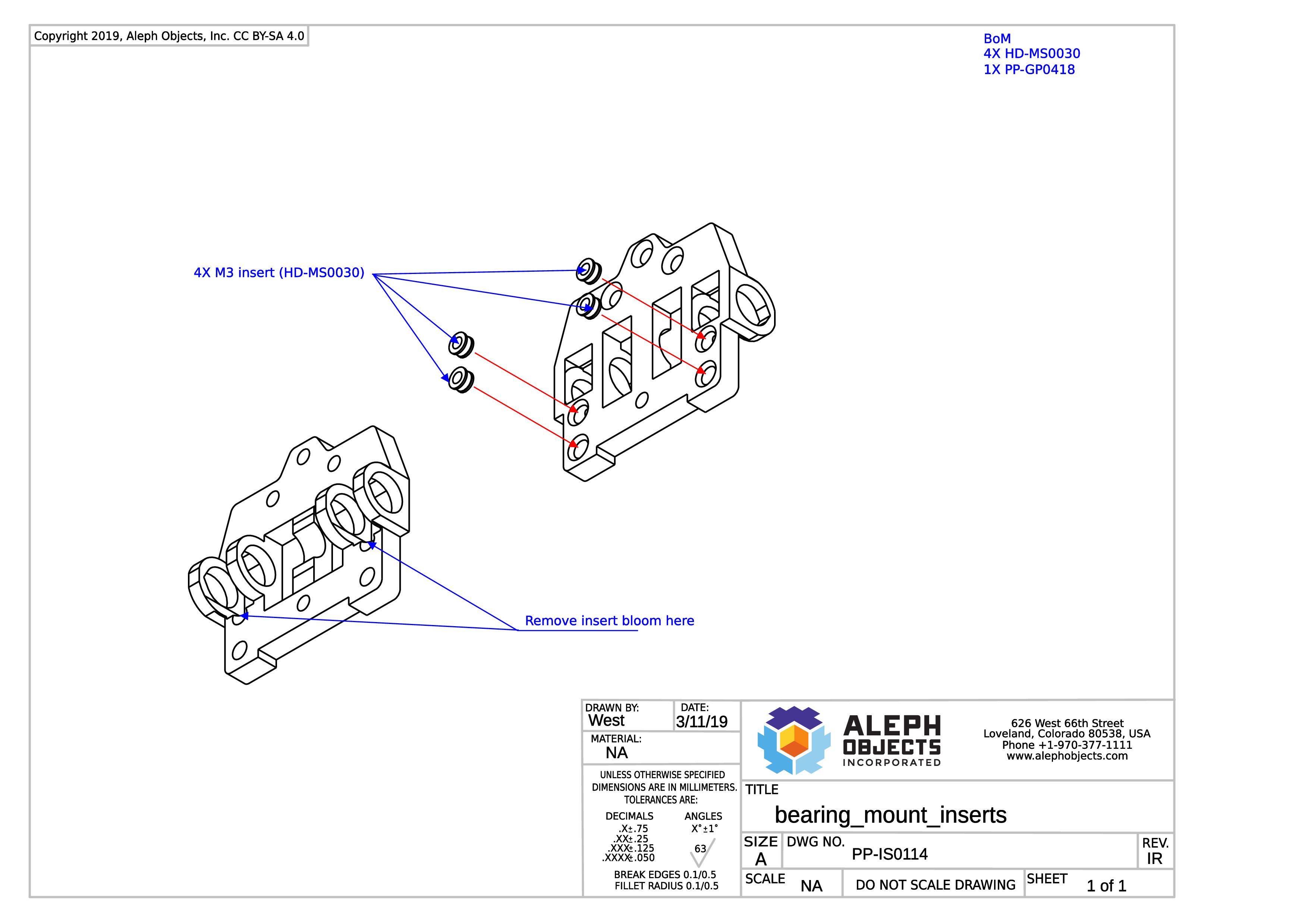
Thermal Insert instructions for PP-IS0114.
Click the link below and go to step 3 for the mechanical assembly procedures.