Open HardwareAssembly Instructions
Guides for installation and assembly of the LulzBot line of products made by Aleph Objects, Inc.
Guides for installation and assembly of the LulzBot line of products made by Aleph Objects, Inc.
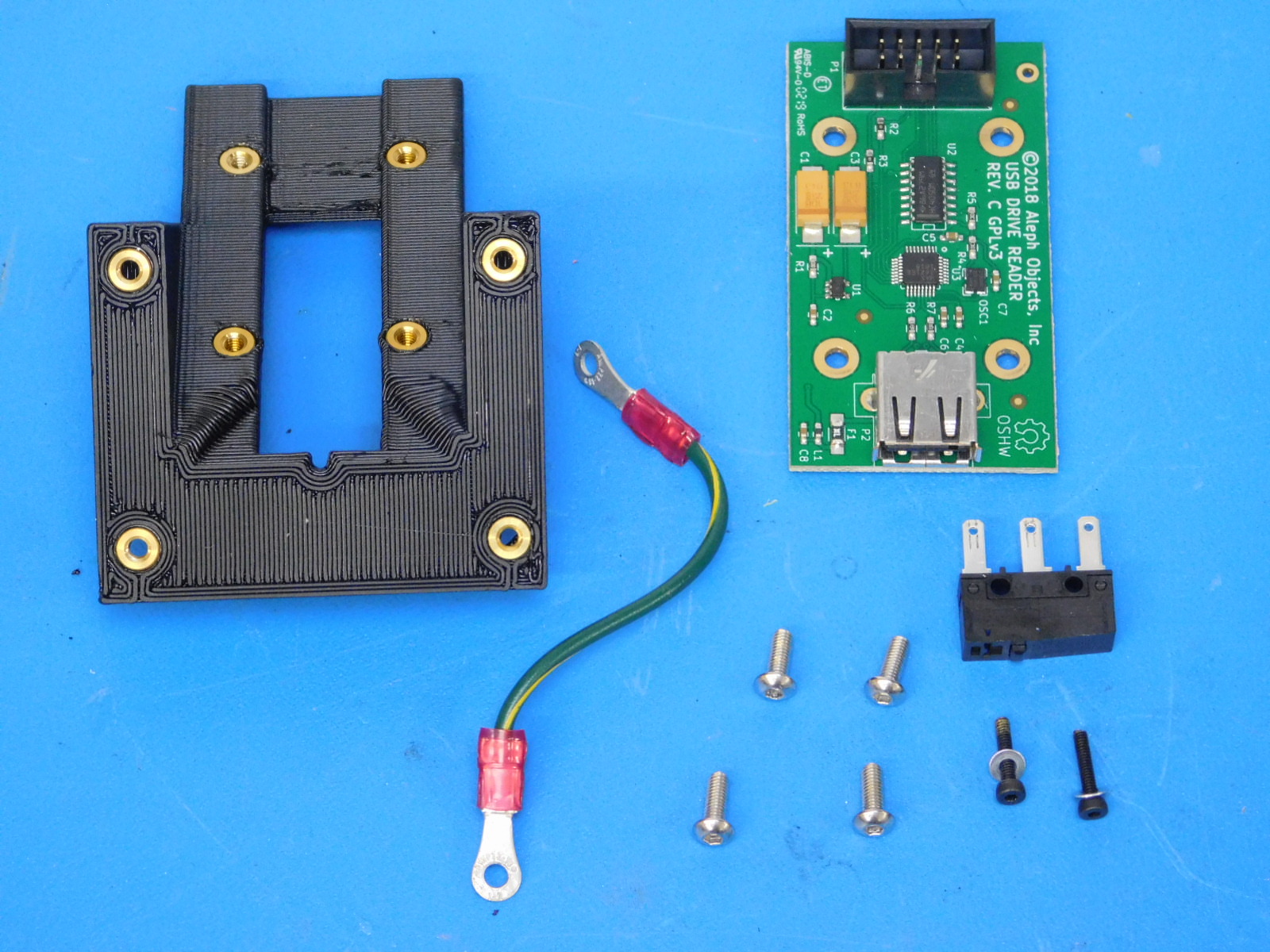
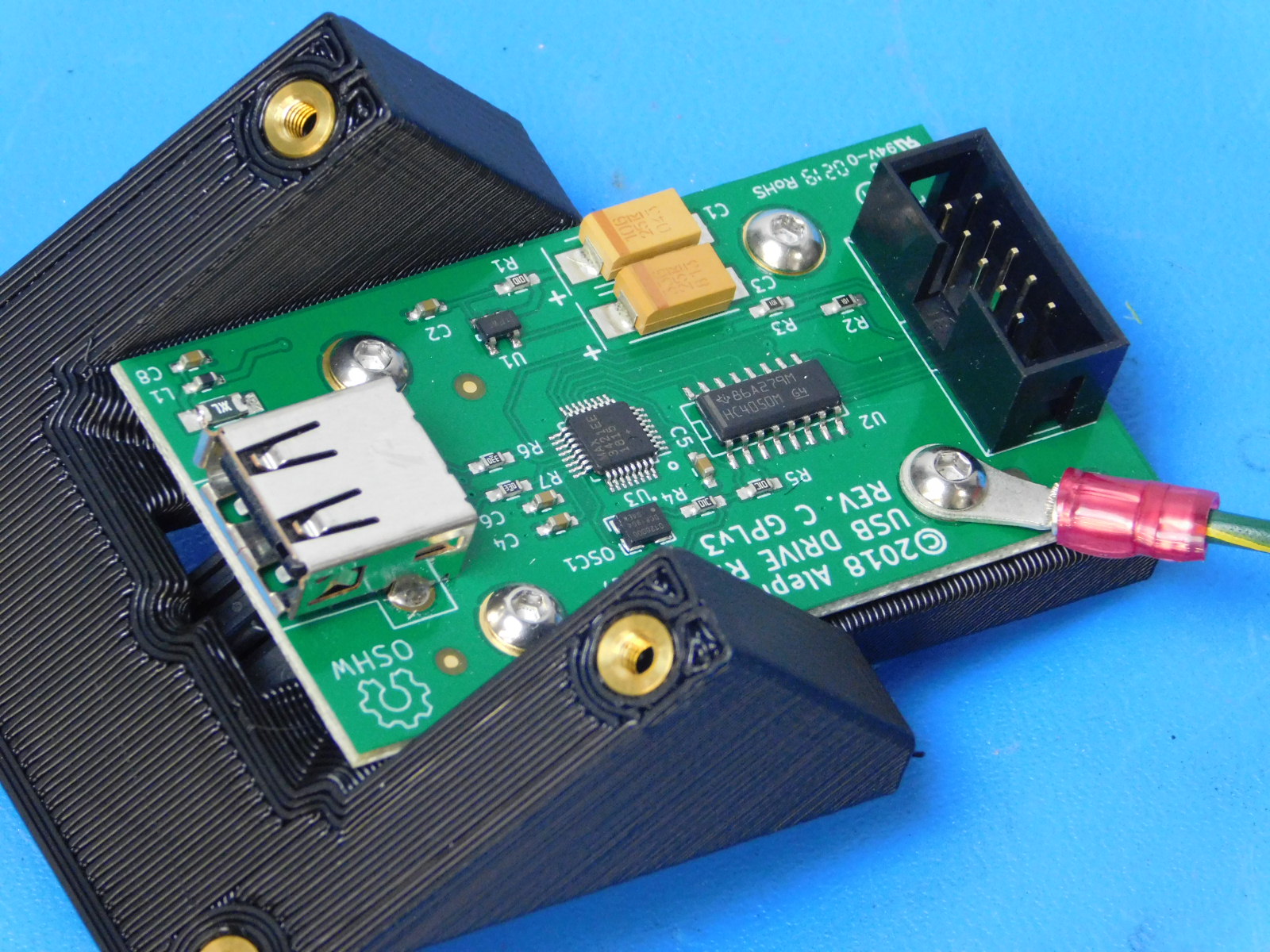
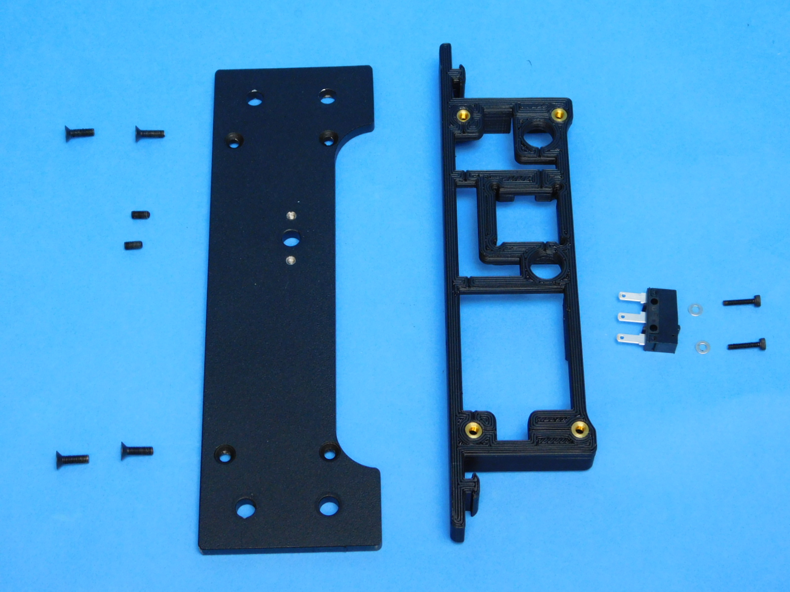
Materials for [AS-PR0119] USB Reader Assembly:
Be sure that you are properly grounded before starting this assembly.
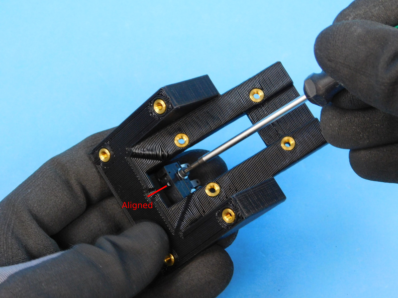
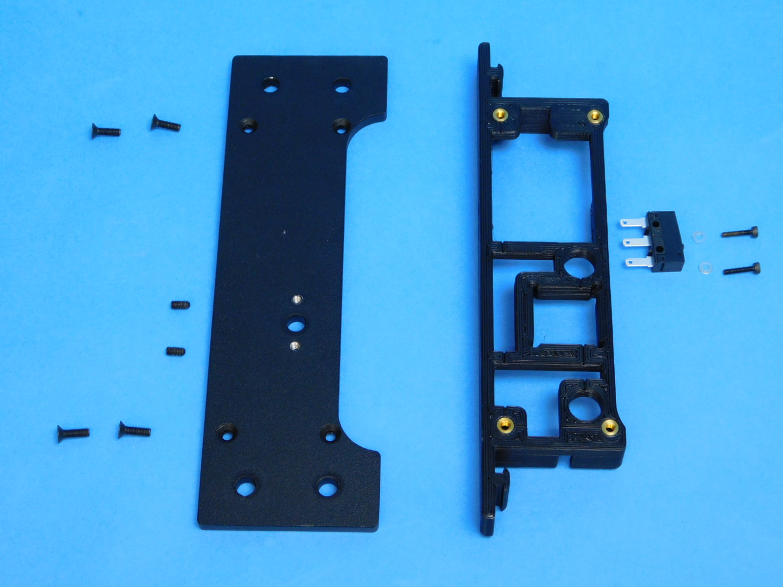
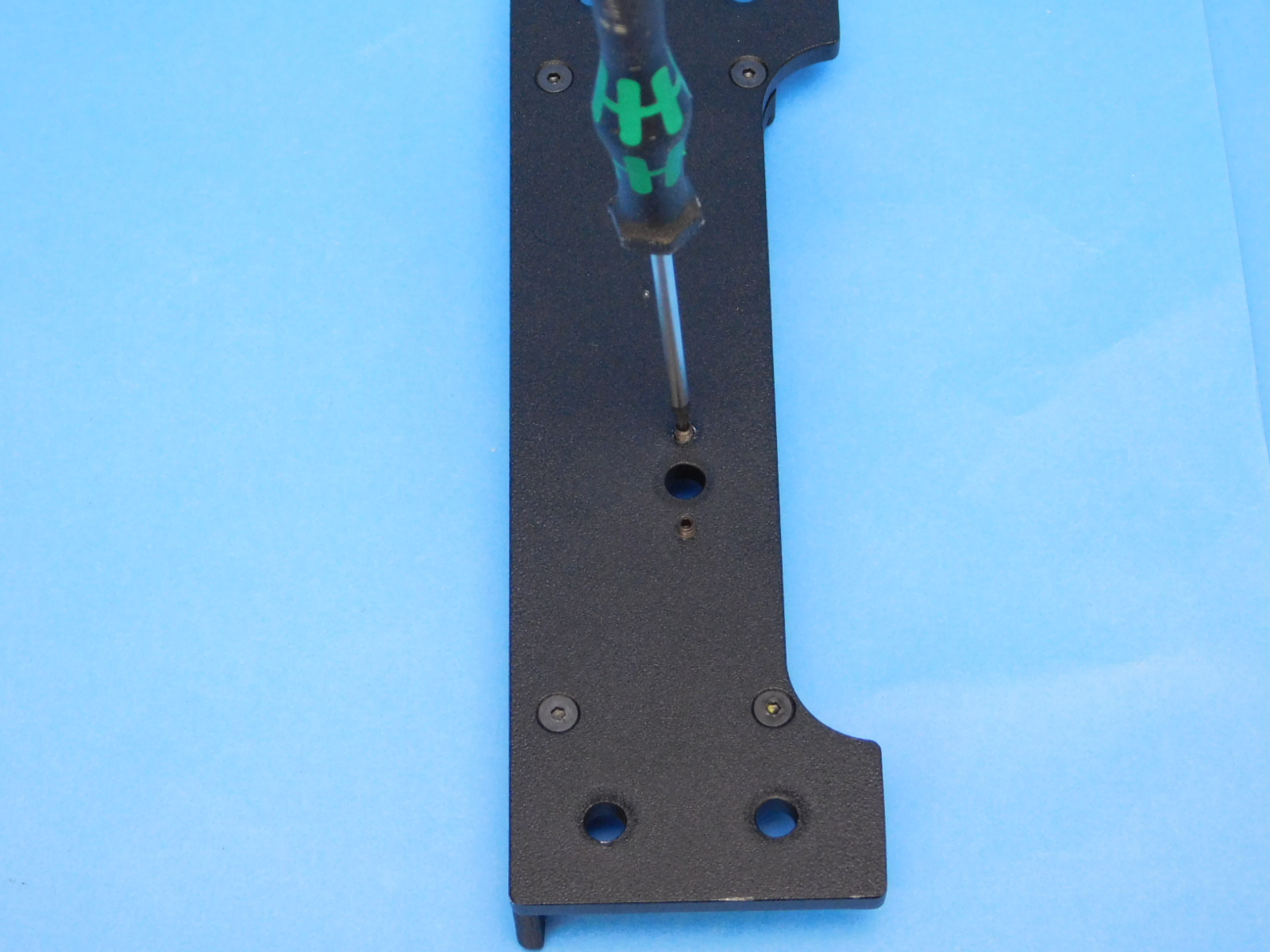
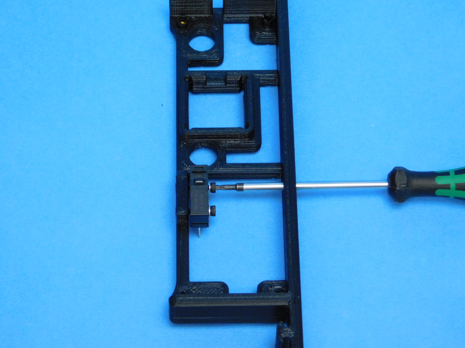
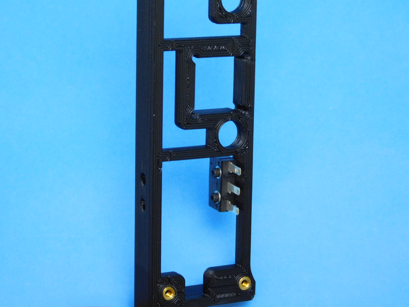
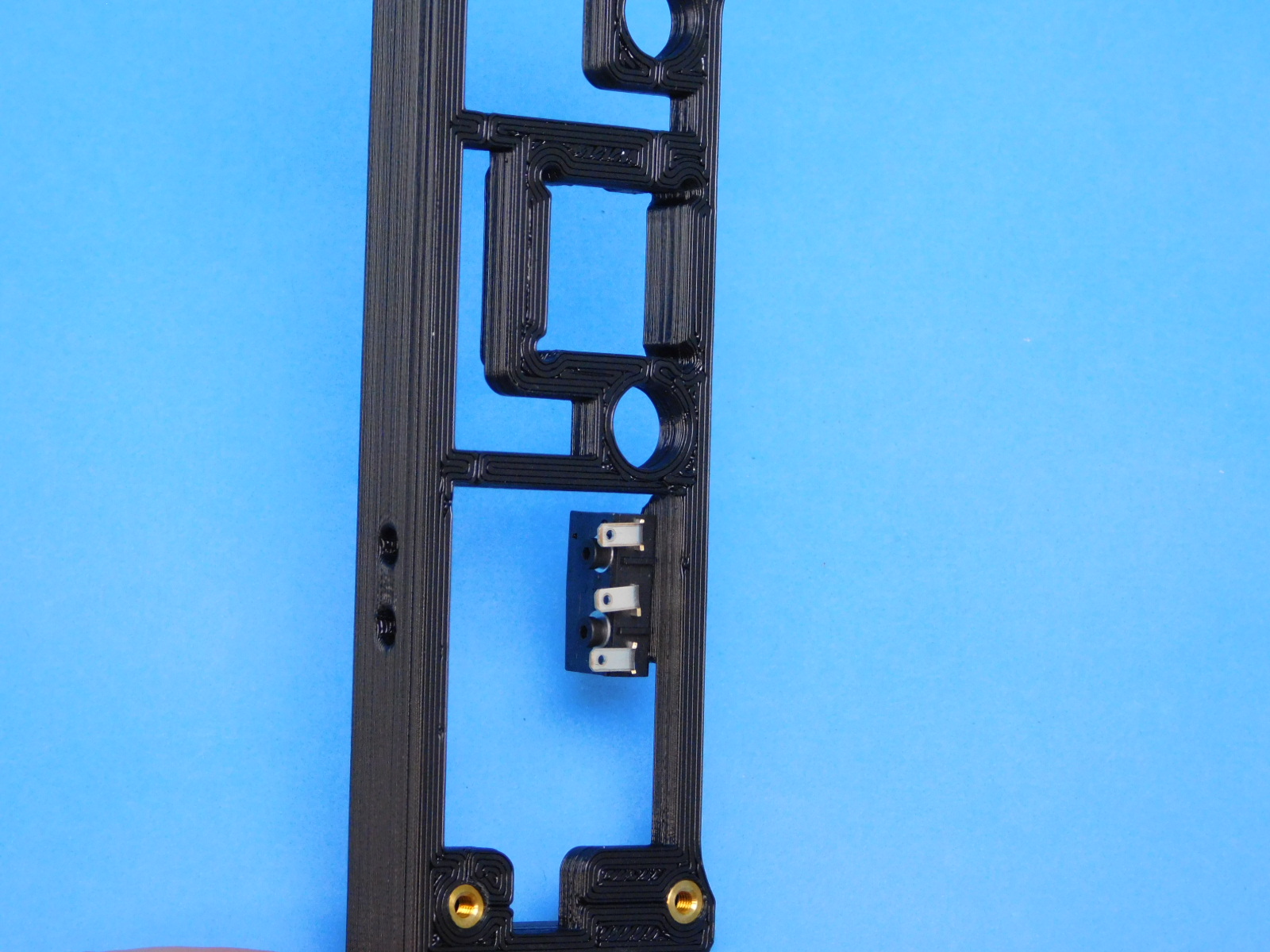
Use the M2X10 SHCS [HD-BT0107] fasteners and [HD-WA0012] M2 Washers to fasten the switch [EL-SW0022] to the USB mount [PP-IS0087].
Make sure that the small hole on the mount is lined up with the switch.
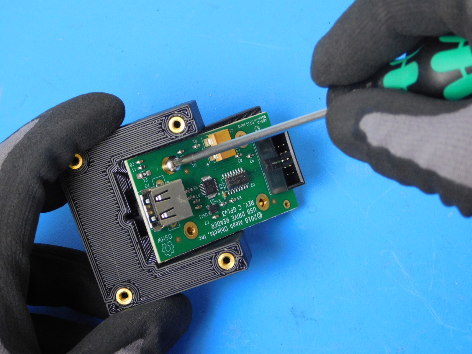
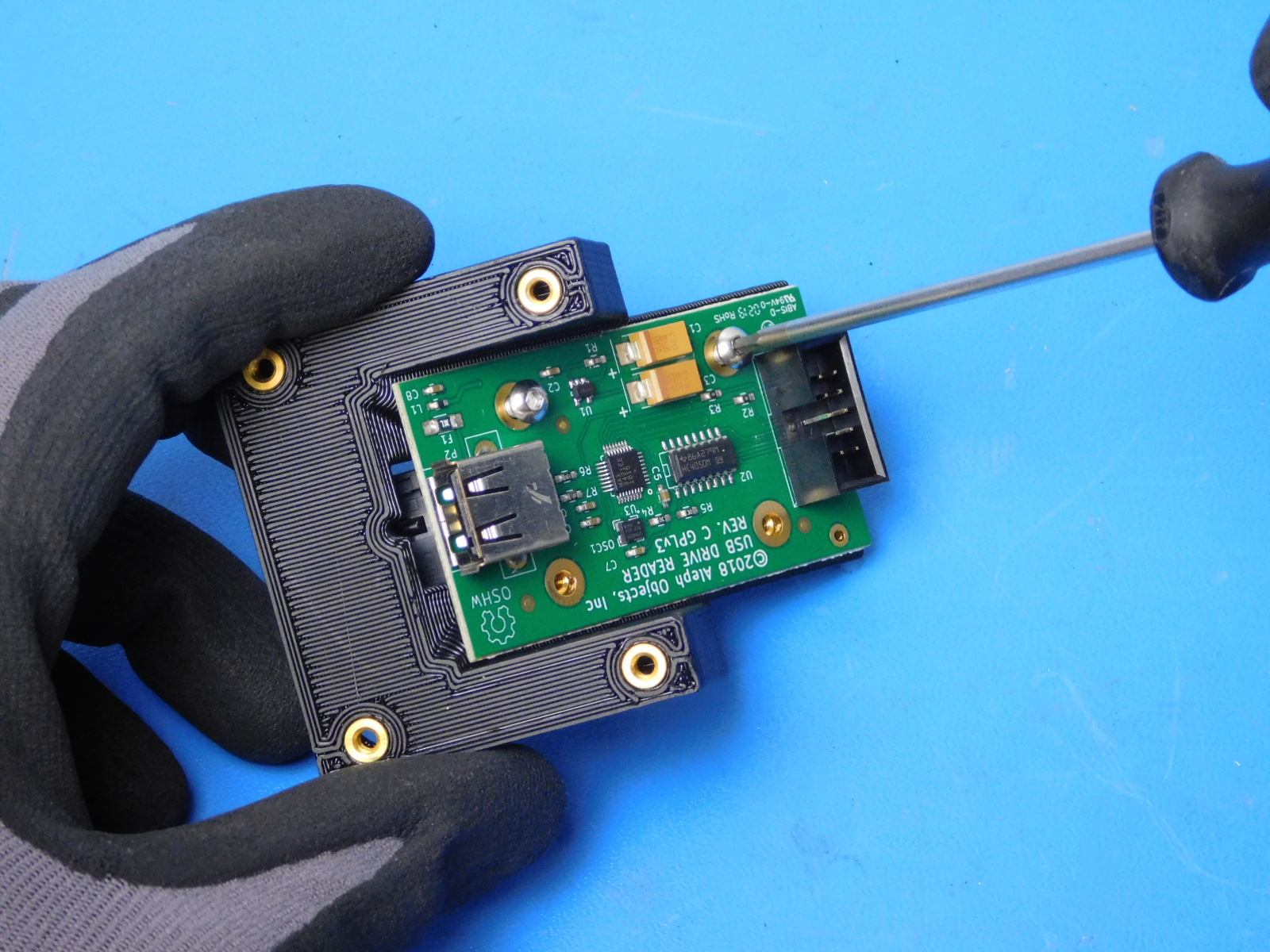
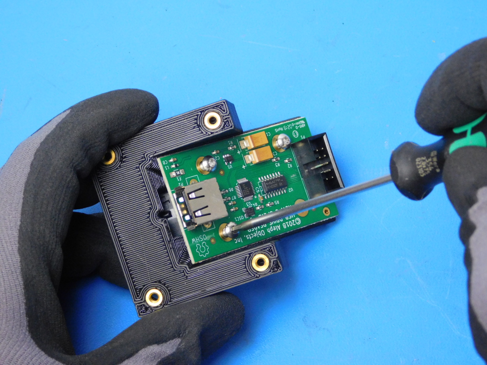
Fasten the USB Reader Board [PC-BD0114] to the USB mount with 3x- M3X8mm BHCS SST [HD-BT0104] fasteners at the locations shown.
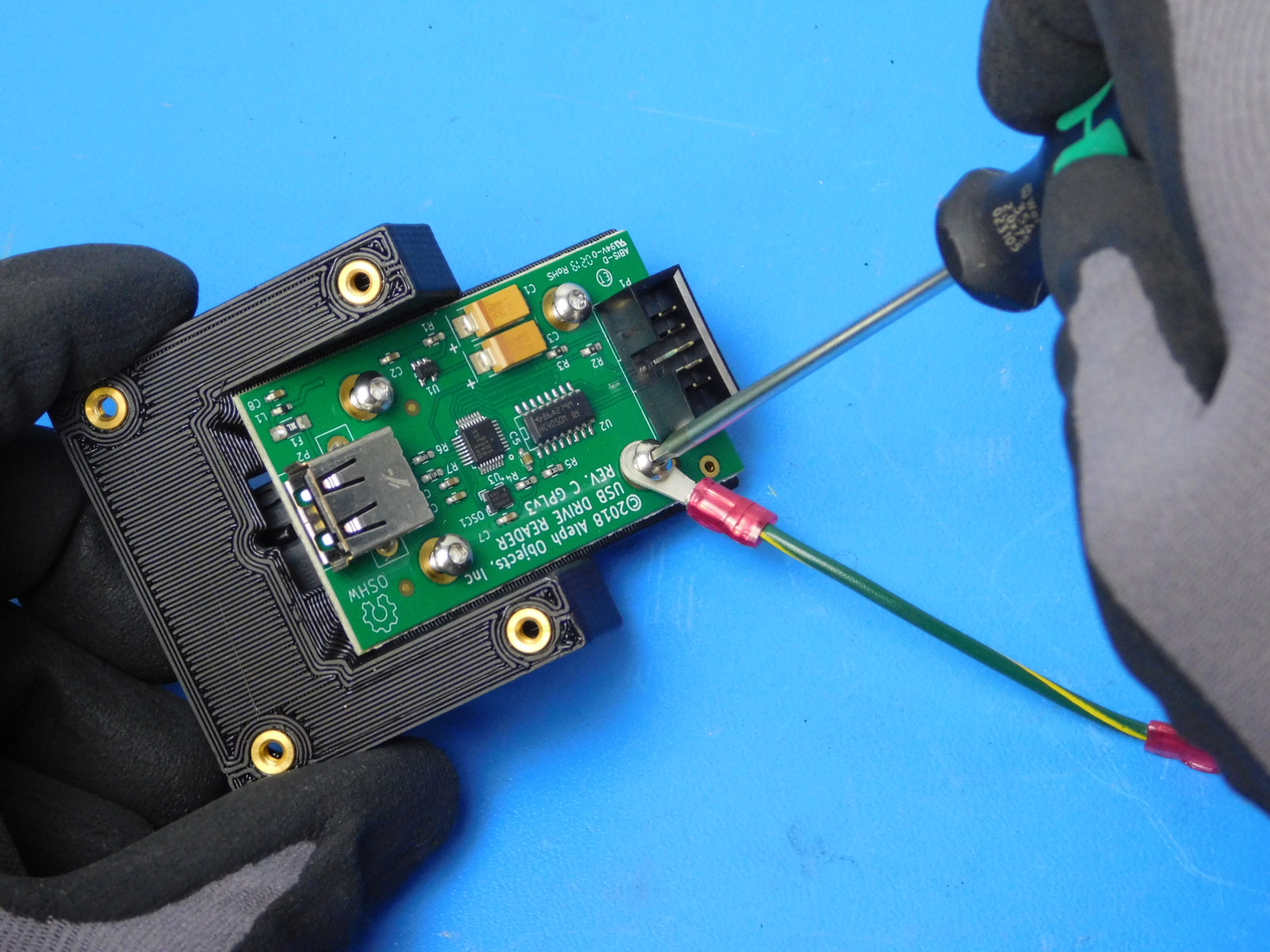
Note the location used to attach EL-HR0164
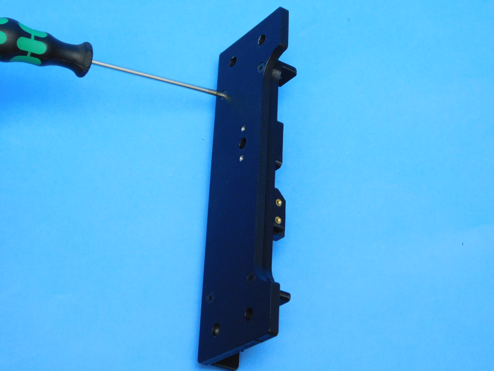
Place one of the terminal rings of the USB Ground Harness [EL-HR0164] onto the last M3x8 SST BHCS [HD-BT0104] and secure it to the location shown.
Make sure that the USB input is oriented towards the direction of the switch.
Torque fasteners to 5in*lbs
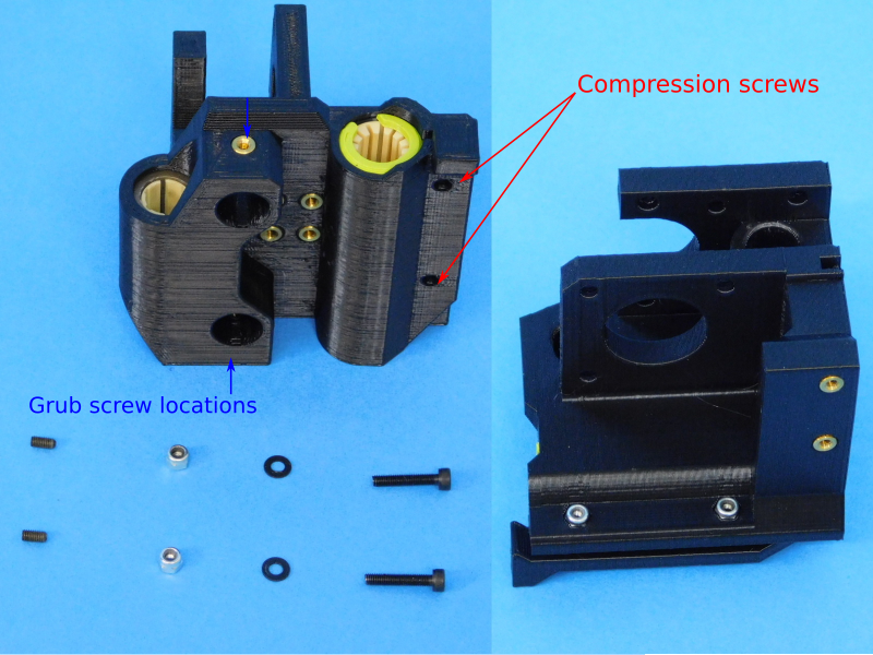
Materials for [AS-PR0133] X-End Motor Sub-Assembly:
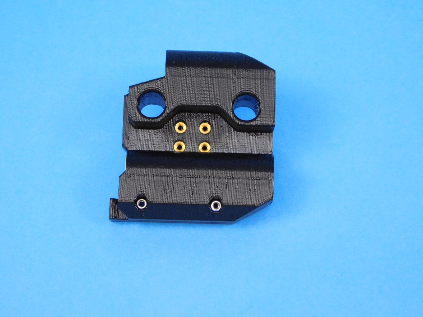
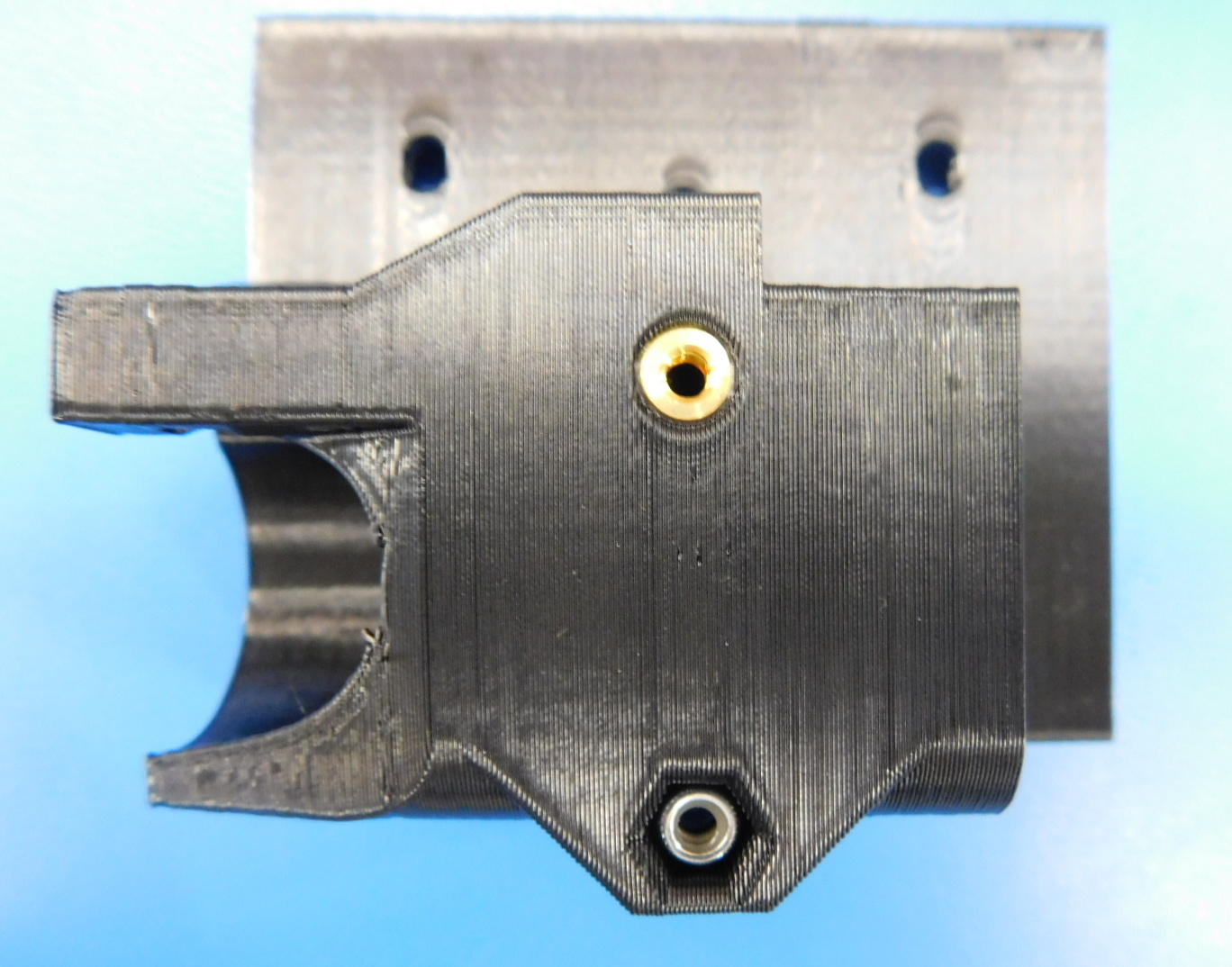
Place 2X [HD-NT0001] Locknut into the nut trap of the compression holes of [AS-PR0132] x-motor with bushings.
Insert 2X [HD-BT0185] M3X16 SHC fastener with [HD-WA0038] into the compression holes for the double bearing but do not tighten all the way.
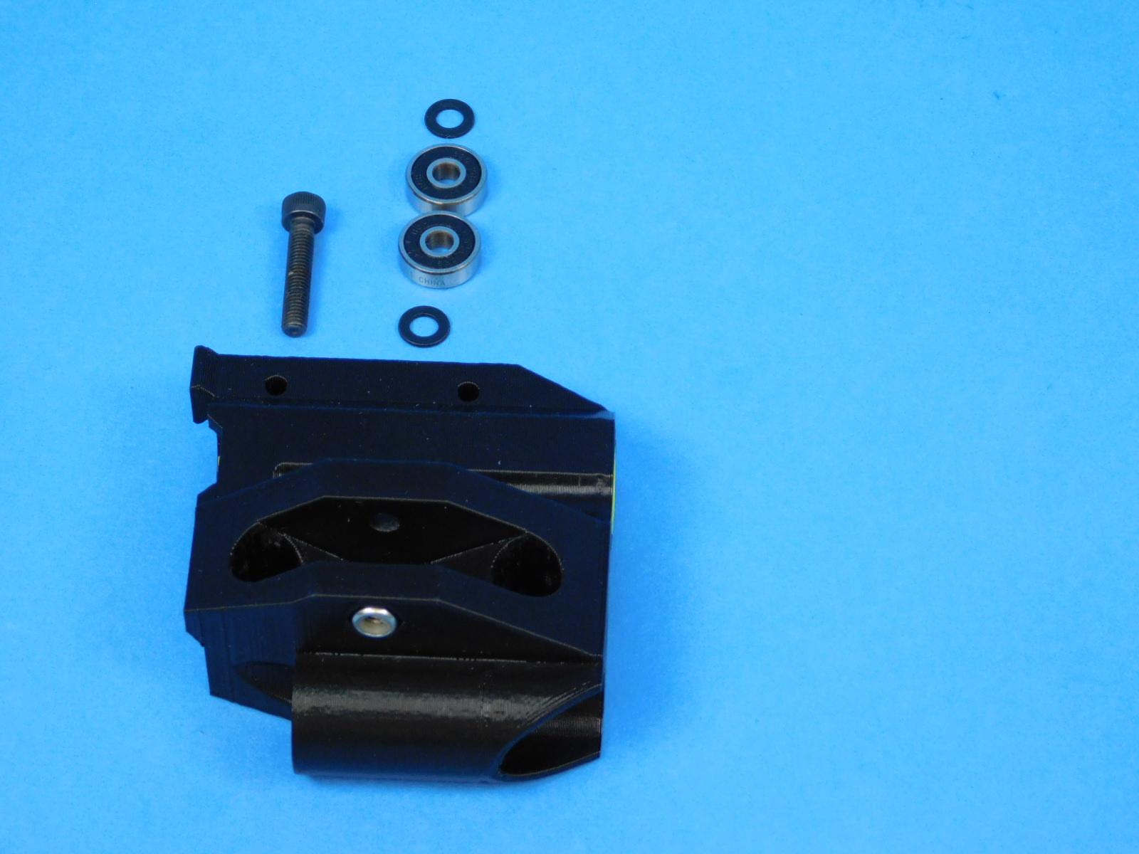
Materials for [AS-PR0129] X-End Idler Assembly:
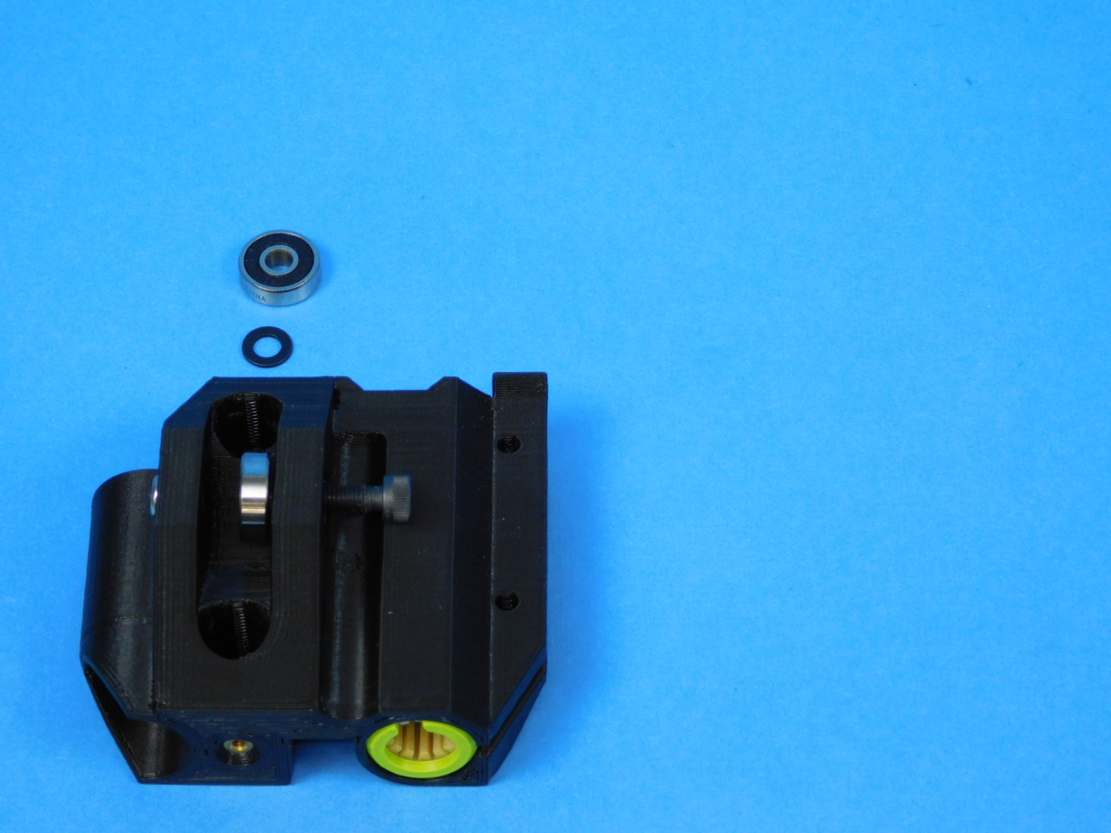
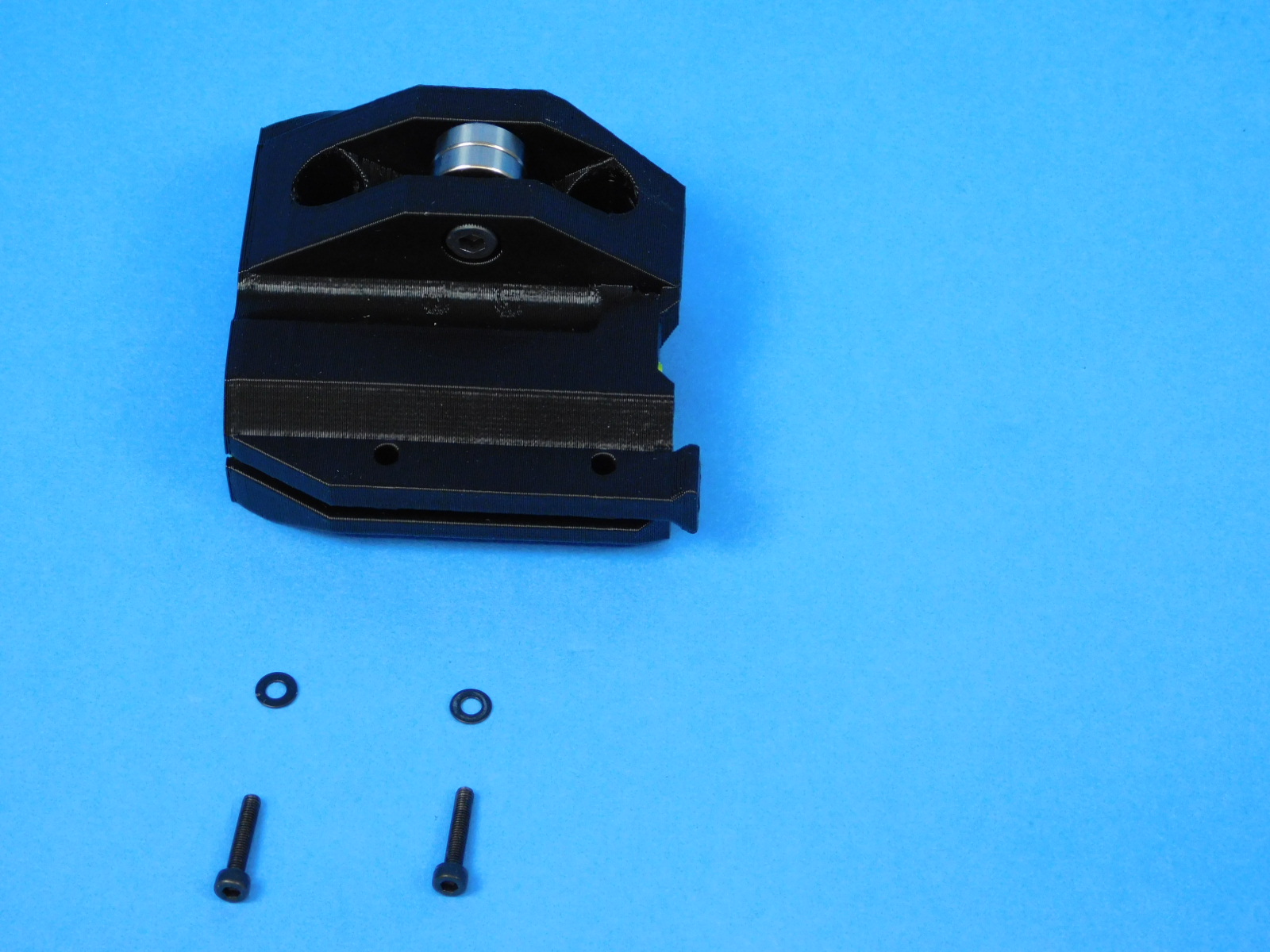
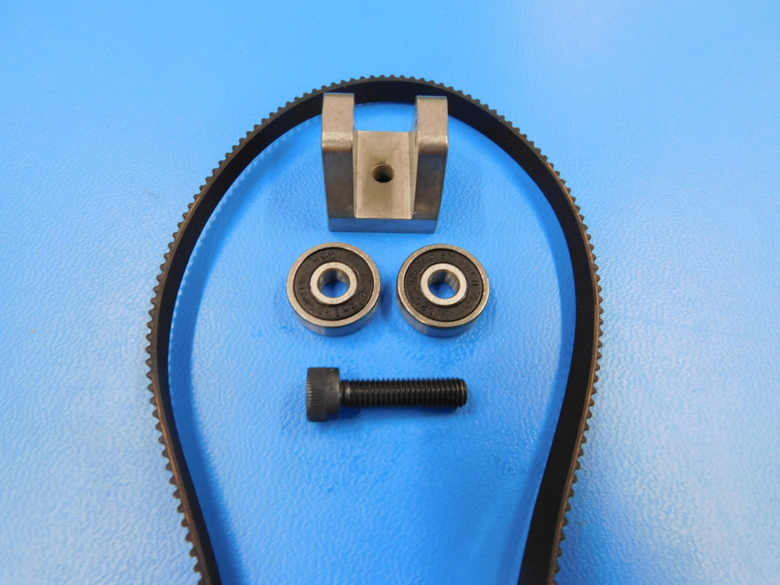
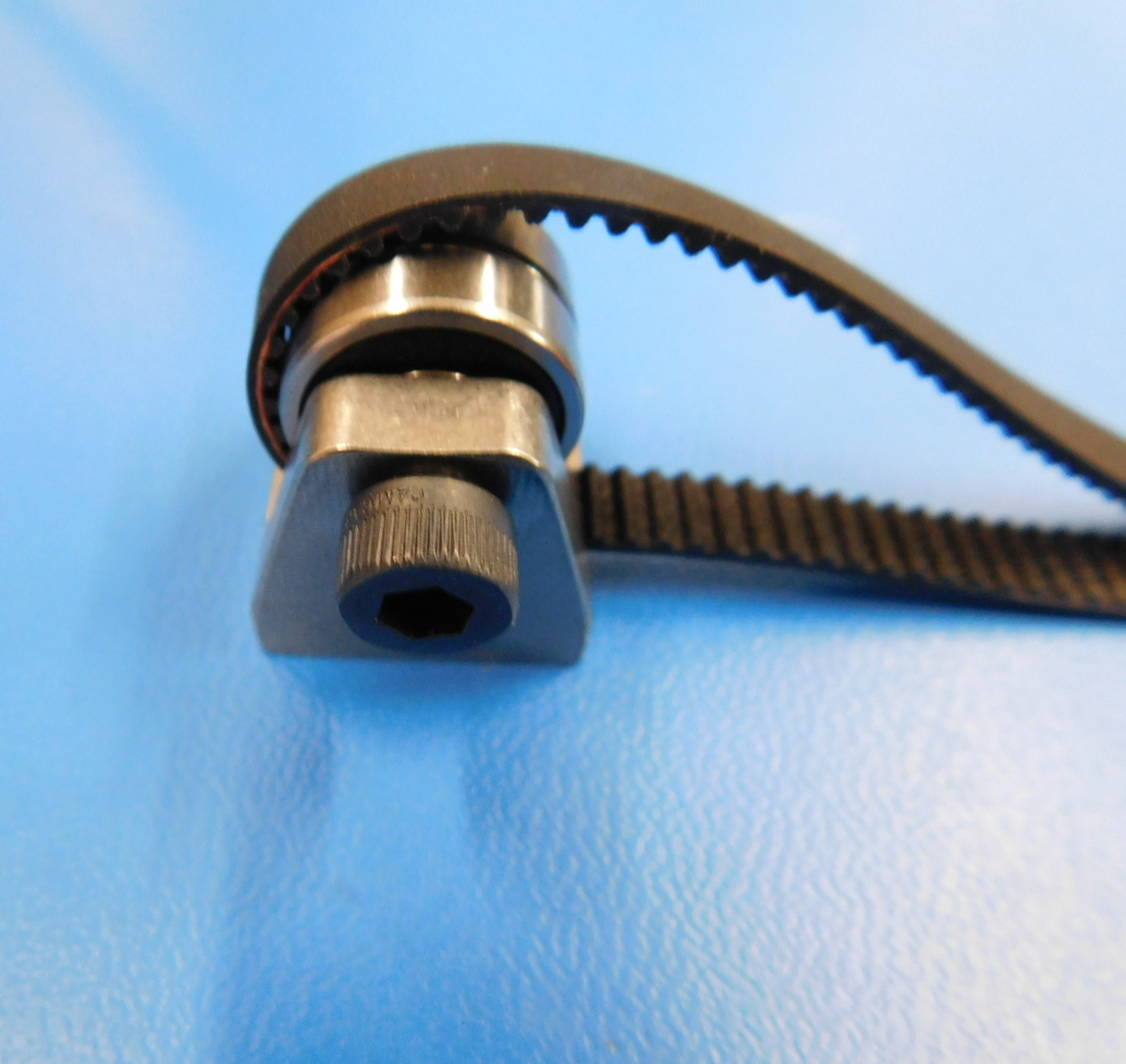
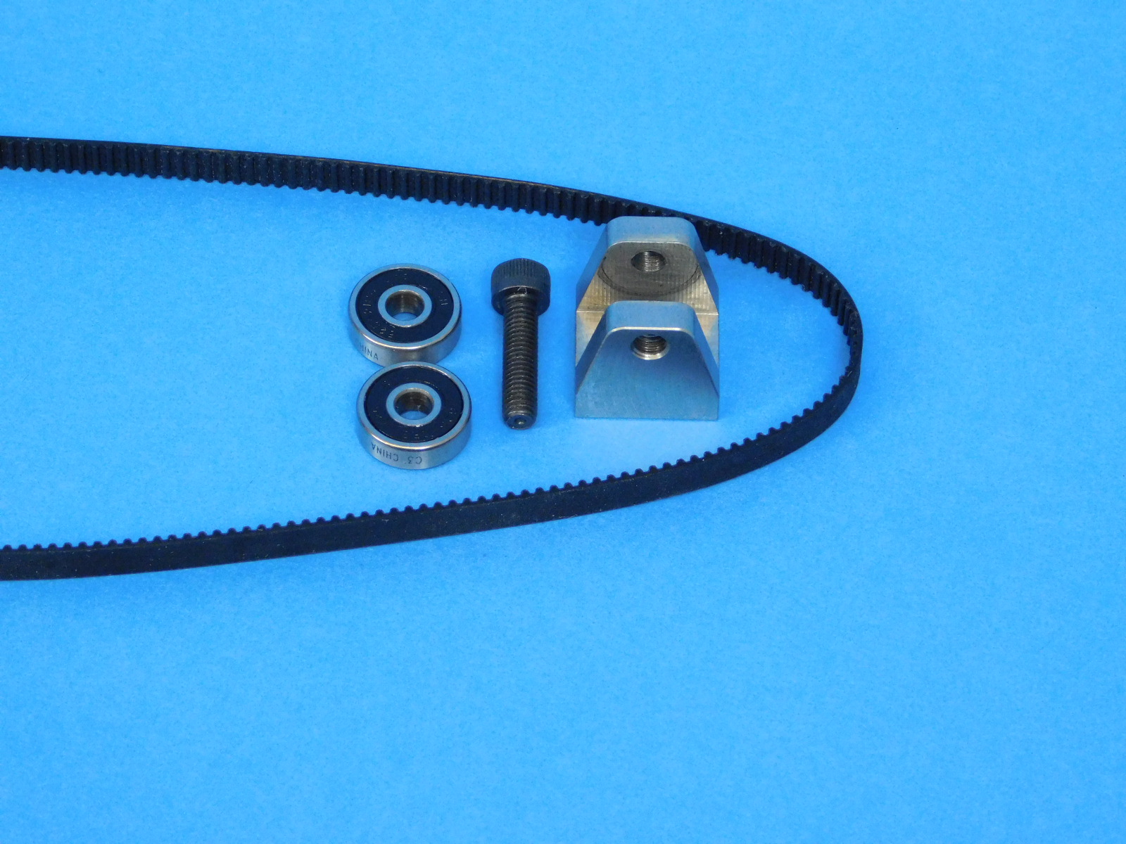
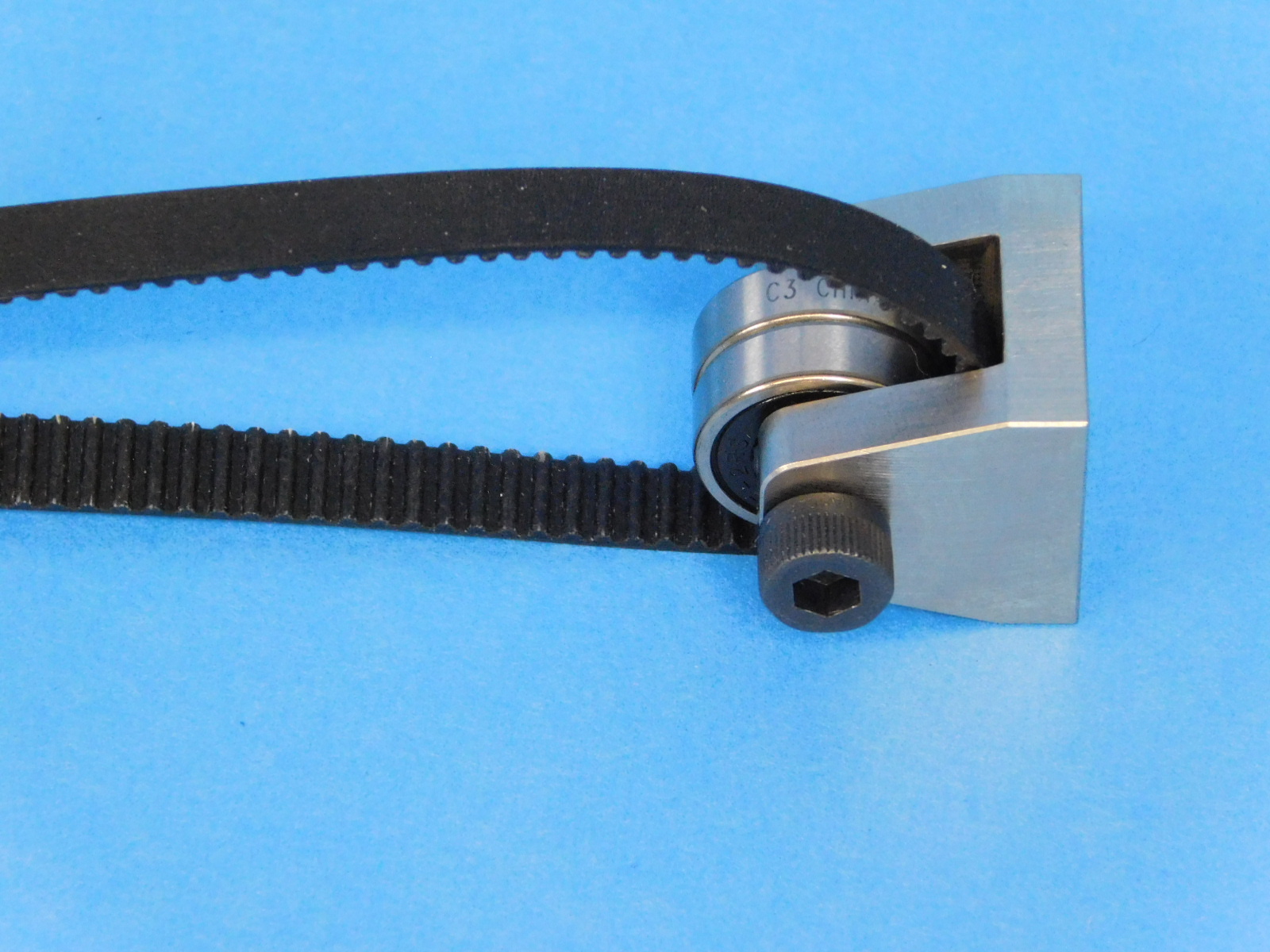
Fasten 2X [HD-MS0411] sealed bearings and 2X [HD-WA0040] M5 washers into the designated slot using 1X [HD-BT0196] M5X25 SHC fastener into 1X [HD-NT0057] M5 Locknut. Be careful to not over tighten this part. The threads should be engaging the nylon in the locknut but not pinching the bearings or part.
Place 2X [HD-NT0001] Locknut into the nut trap of the compression holes of [AS-PR0132] x-motor with bushings.
Insert 2X [HD-BT0185] M3X16 SHC fastener with [HD-WA0038] into the compression holes for the double bearing but do not tighten all the way.
Materials needed for the X-Carriage Sub-Assembly [AS-PR0143]:
See step 22 for X-Carriage Sub-Assembly [AS-PR0143] Insert Instructions
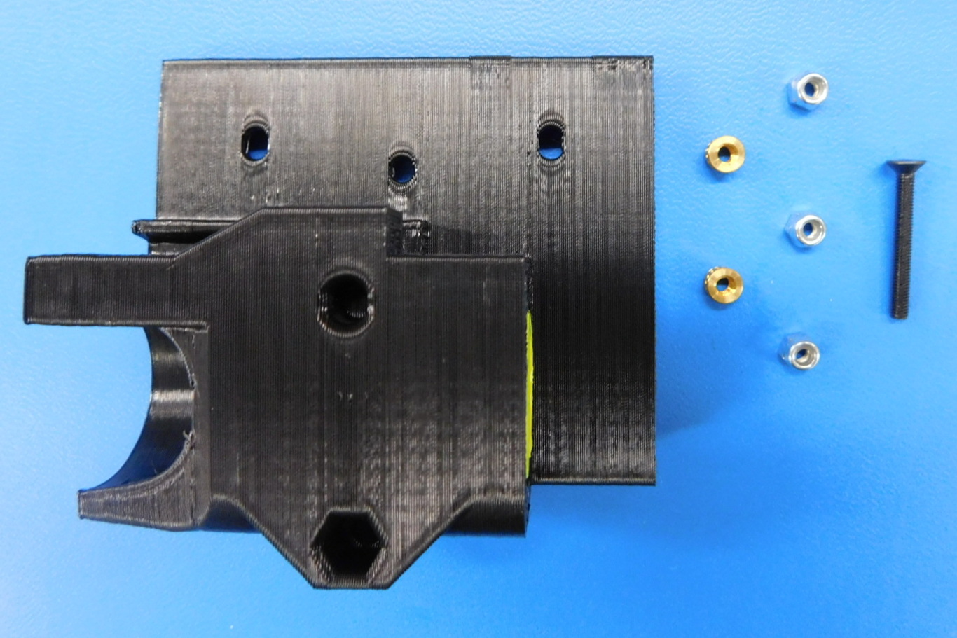
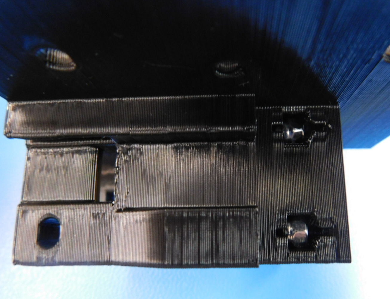
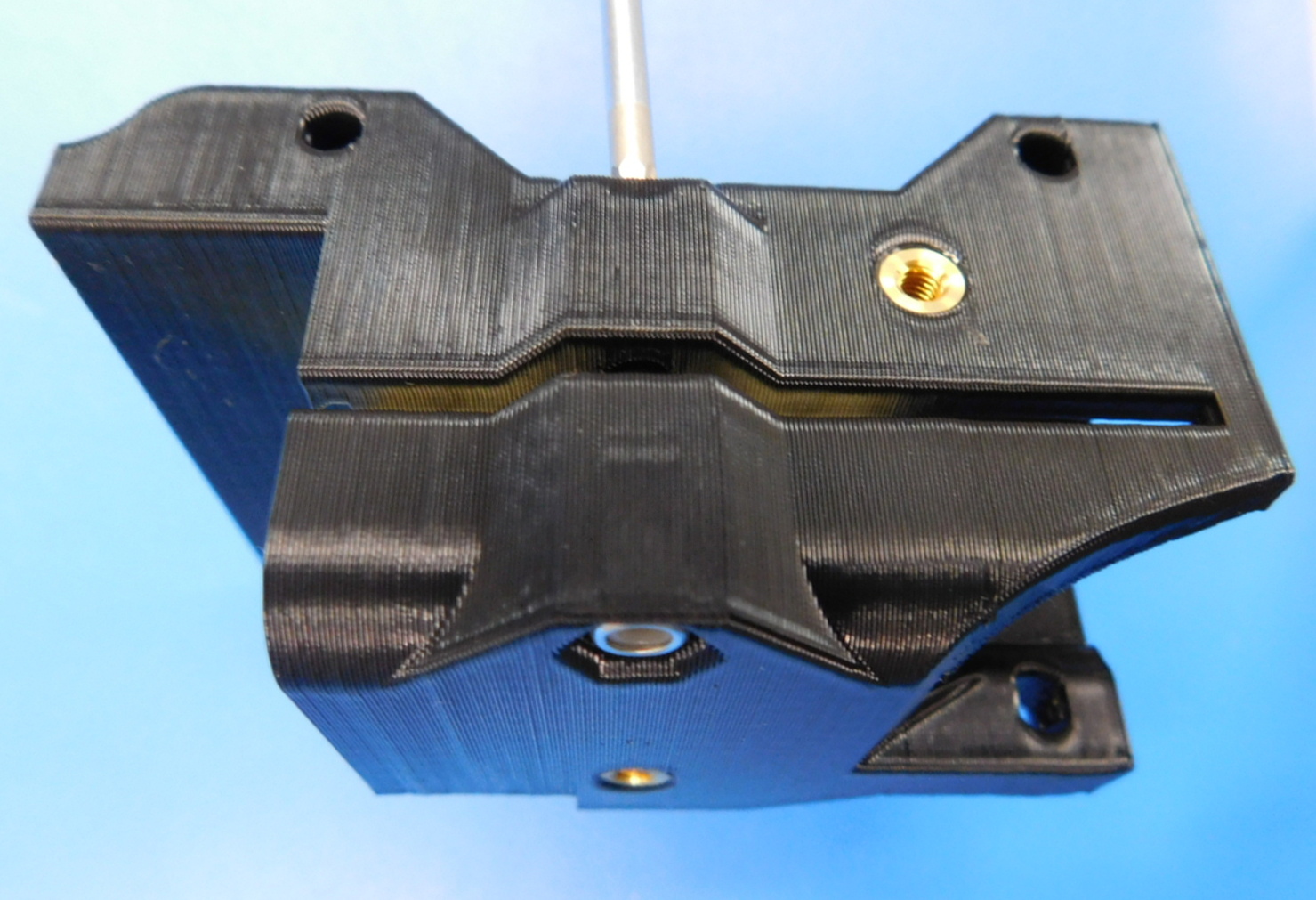
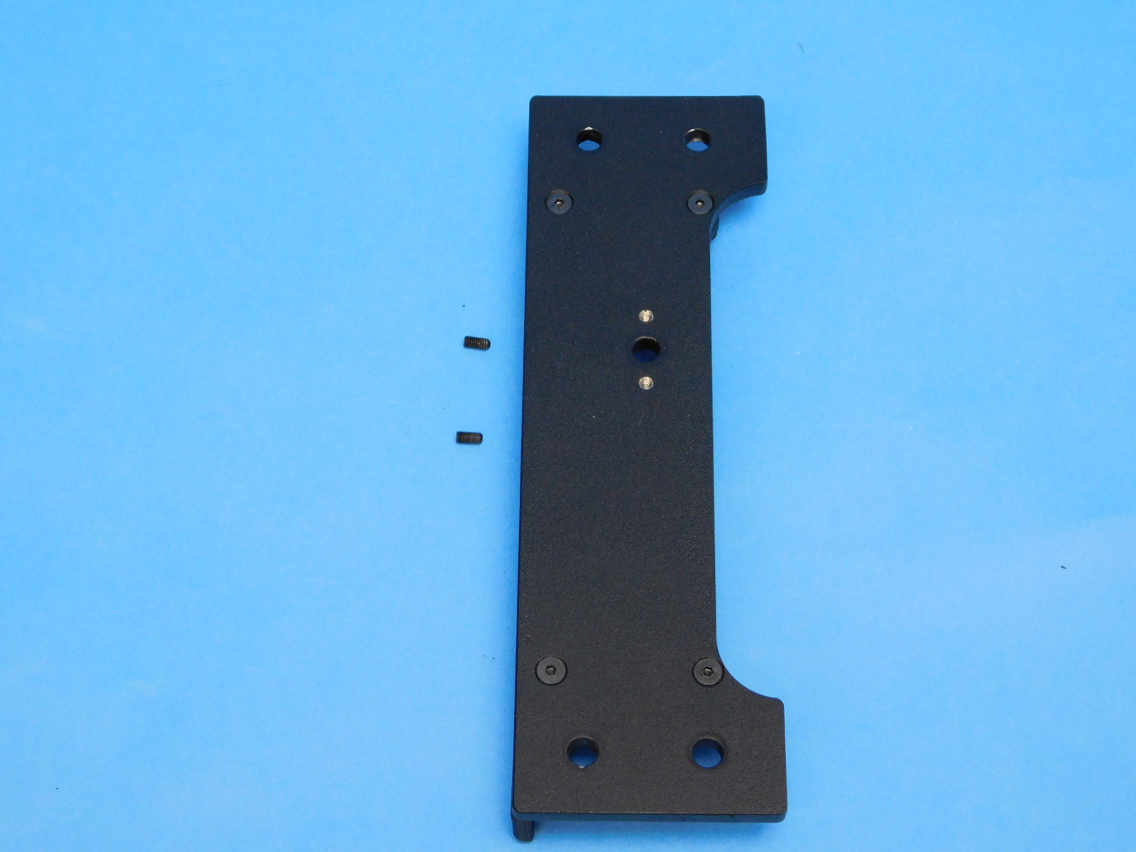
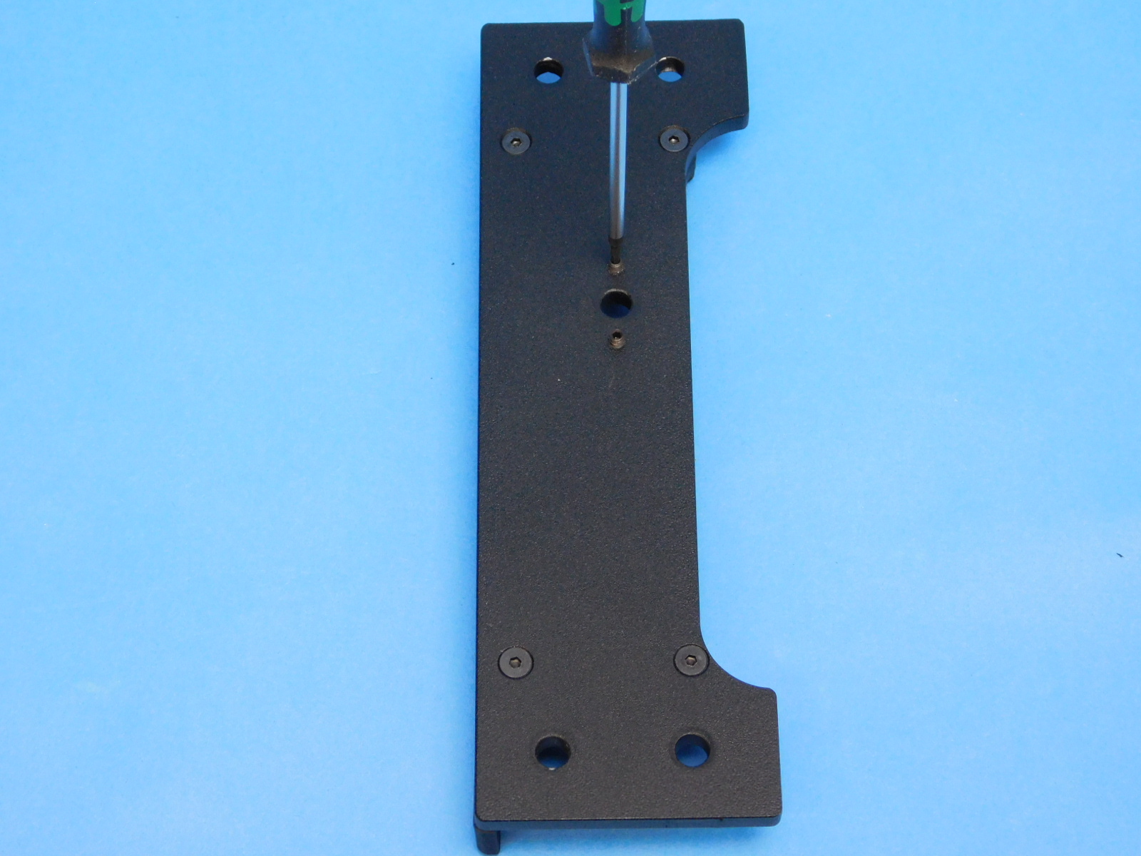
Place the 2x [HD-NT0001] M3 Nylon Locknuts into the 2 pockets shown in the image, with the nylon facing the center of the part.
Install the [HD-BT0206] M3 x 25mm screw using the [HD-NT0001] Nylon Locknut as shown in the image.
Materials for [AS-PR0124] Y-Idler Assembly
Place the [HD-BL0028] rubber belt's smoothed side against the back of the [PP-MP0225] YZ idler.
Fasten 1X [HD-BT0151] M5X20 SCHS into the YZ idler and through 2X [HD-MS0411] rubber sealed bearing.
Materials for [AS-PR0129] Z Idler Assembly
Place the [HD-BL0023] rubber belt's smoothed side against the back of the [PP-MP0225] YZ idler.
Fasten 1X [HD-BT0151] M5X20 SCHS into the YZ idler and through 2X [HD-MS0411] rubber sealed bearing.
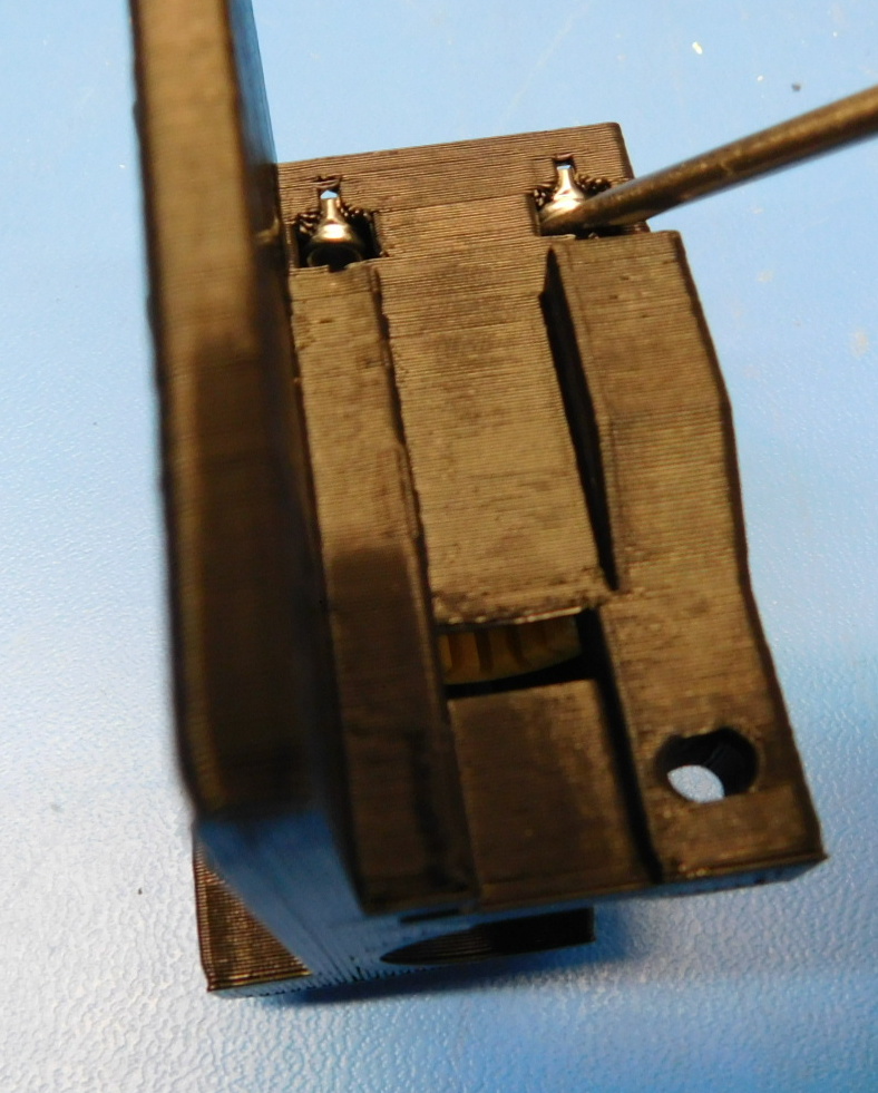
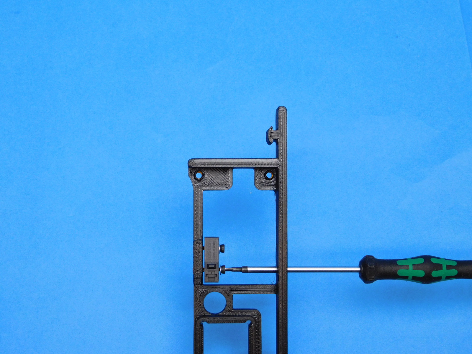
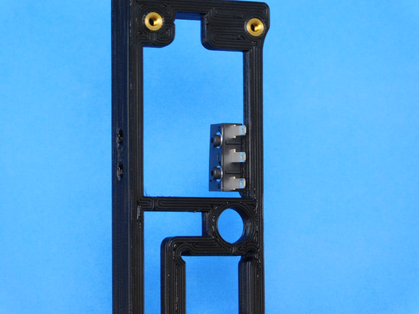
Fasten one Z-max switch [EL-SW0022] to the Z-Upper [PP-IS0093] using 2x M2X10 SHCs [HD-BT0107] with washers [HD-WA0012], as pictured.
Ensure the button of the switch is closest to the round smooth rod holes of the printed part.
Bend the switch tabs at a 90 degree angle, as pictured.
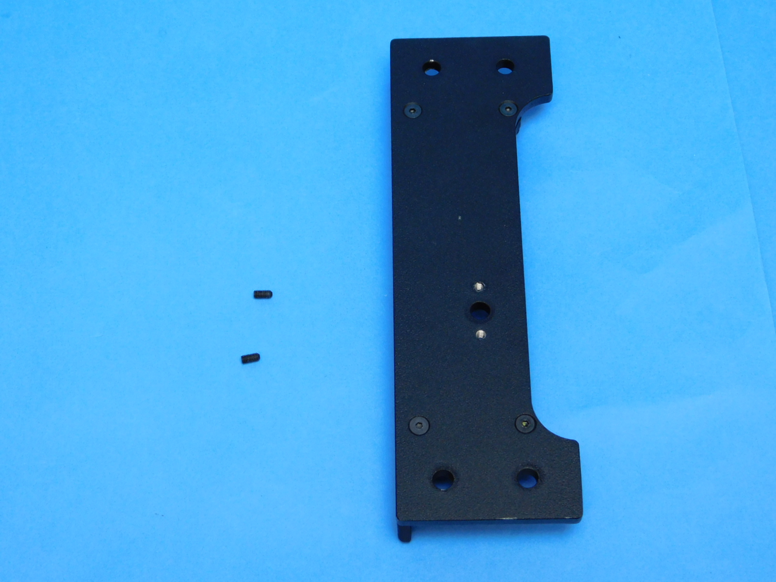
Fasten the Z-upper top plate [PP-FP0156] to the Z-upper right with inserts [PP-IS0093] using 4x M3X10 FHCS [HD-BT0116]
Torque to 5in*lbs
Install 2x M3 Set Screws [HD-BT0012] on to the top of the z-upper top plate.
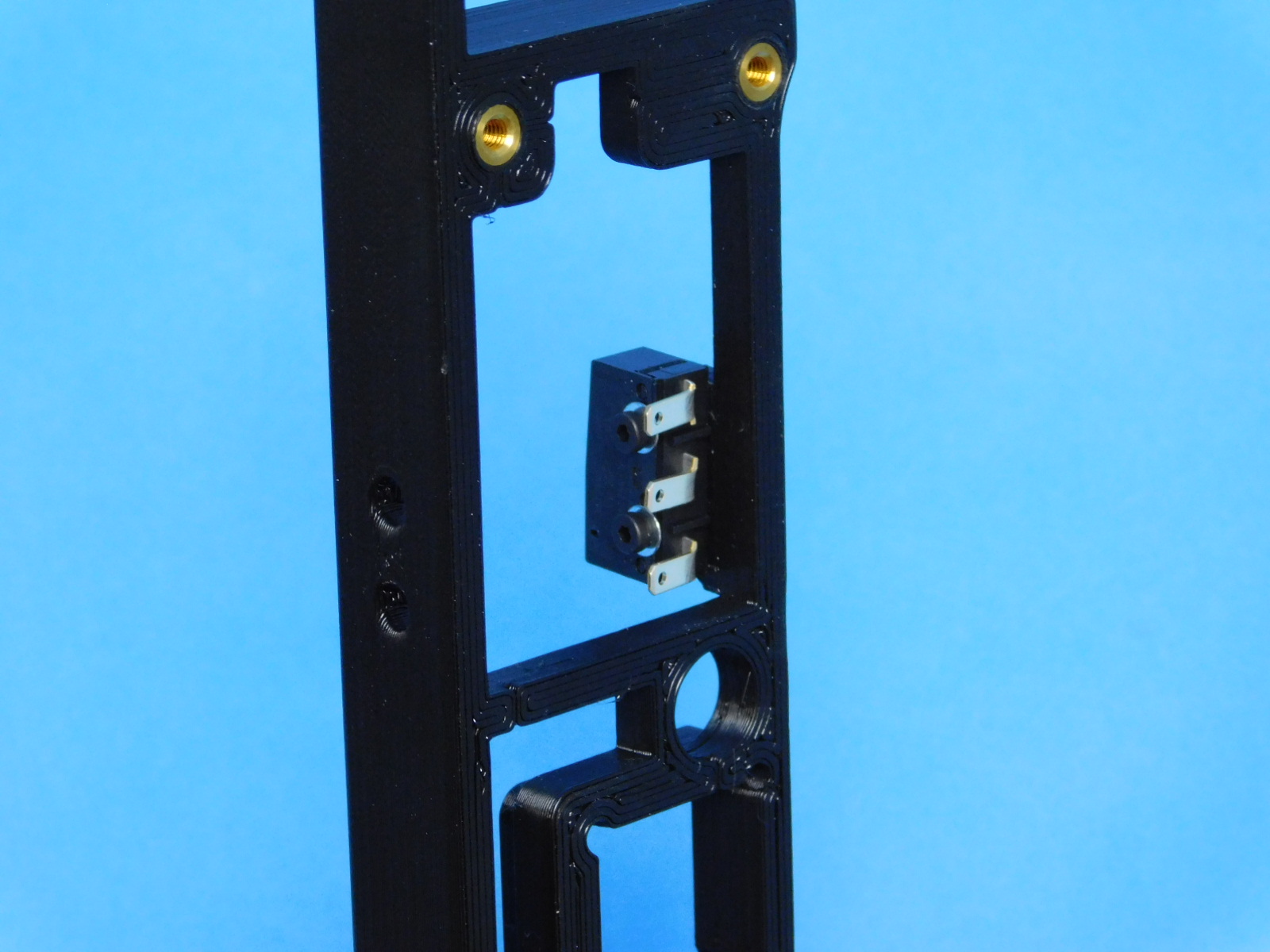

Fasten one Z-max switch [EL-SW0022] to the Z-Upper using 2x M2X10 SHCs [HD-BT0107] with washers [HD-WA0012], as pictured.
Ensure the button of the switch is closest to the round smooth rod holes of the printed part.
Bend the switch tabs at a 90 degree angle, as pictured.
Fasten the Z-upper top plate [PP-FP0156] to the Z-upper left with inserts [PP-IS0094] using 4x M3X10 FHCS [HD-BT0116]
Torque to 5in*lbs
Install 2x M3 Set Screws [HD-BT0012] on to the top of the z-upper top plate.
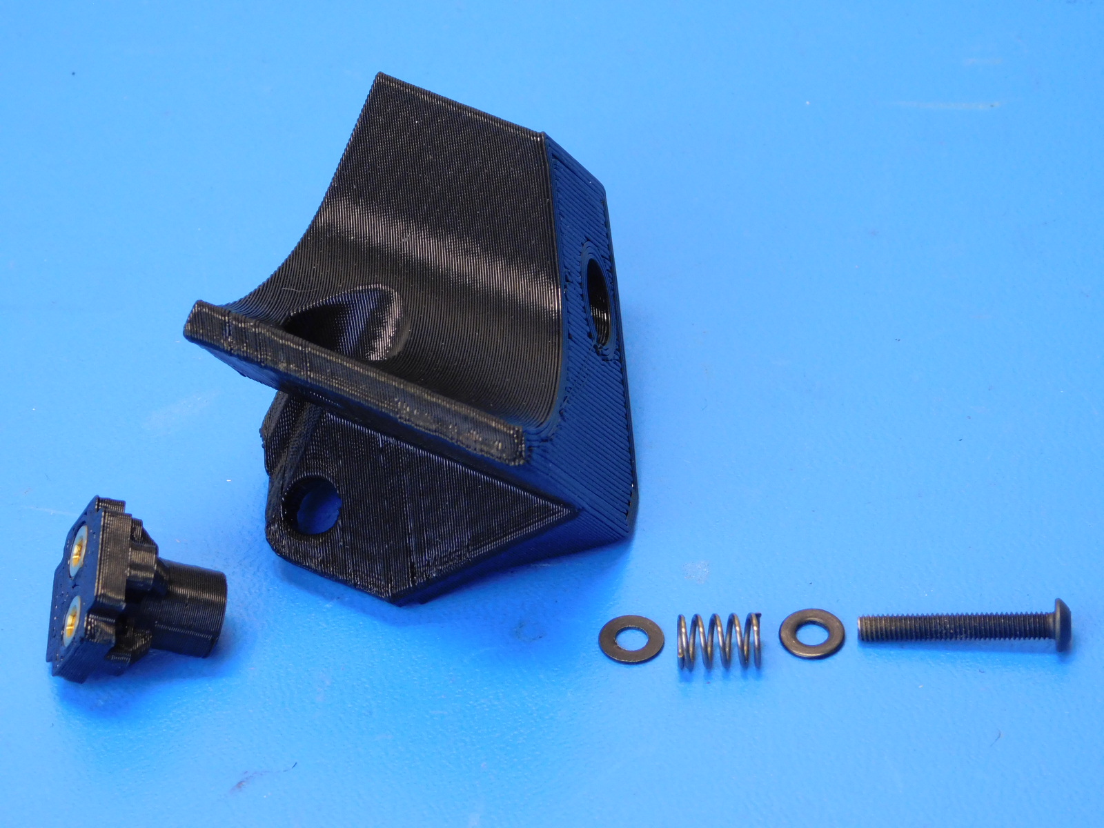
Required materials:
1x- [HD-BT0171] M3x20 BHCS, Black Oxide
1x- [HD-MS0471] Round compression spring .22OD 21lbs/in
2x- [HD-WA0038] M3 Washer, Black Oxide
1x- [PP-IS0096] Y Chain Pivot w/ Inserts, Taz Pro
1x- [PP-GP0367] Y Chain Pivot Mount
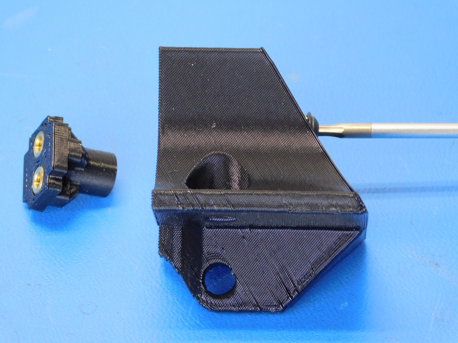
On the M3x20 BHCS [HD-BT0171] place one M3 Washer [HD-WA0038] followed by the Compression Spring [HD-MS0471] and the last M3 washer [HD-WA0038]
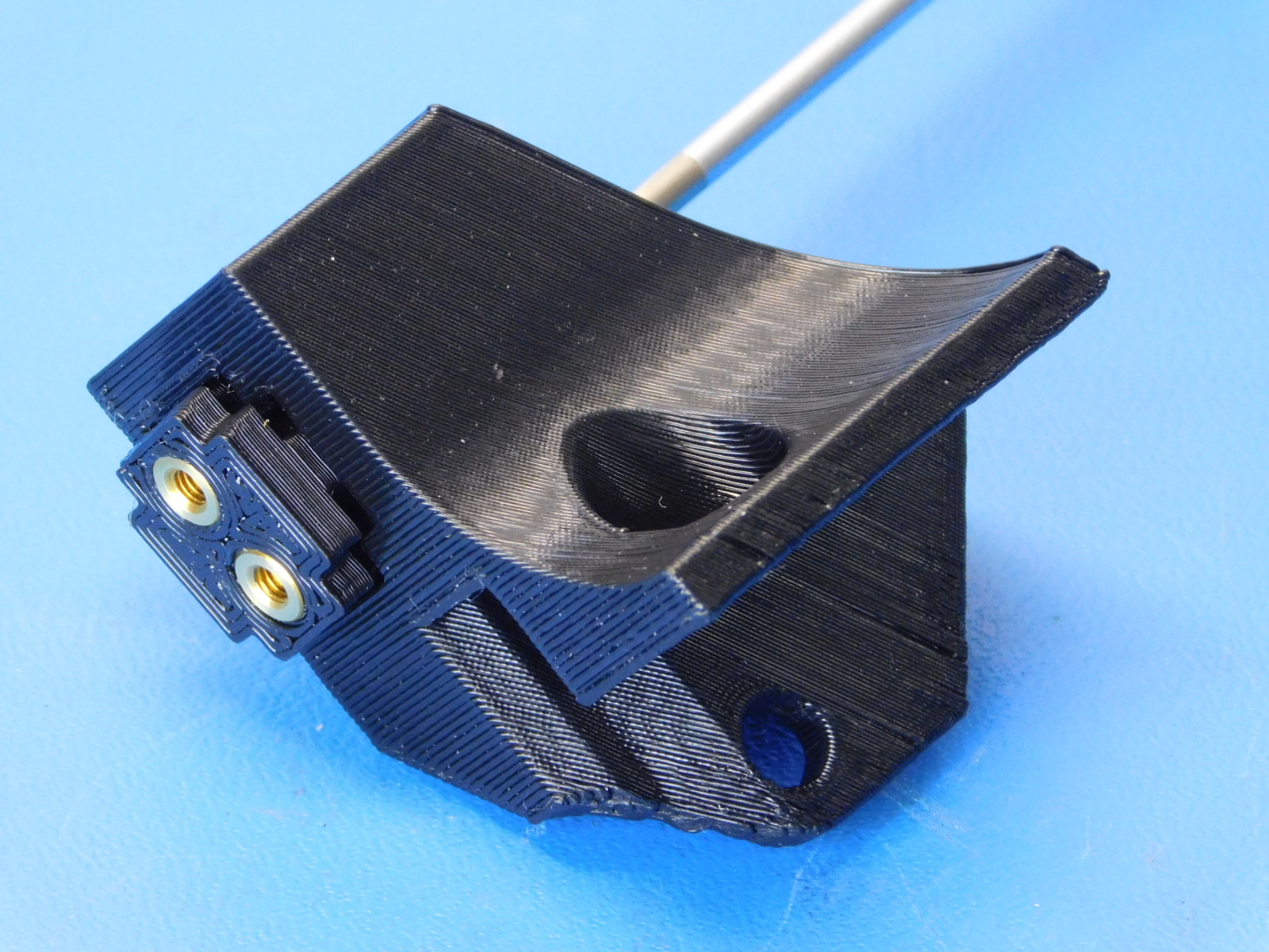
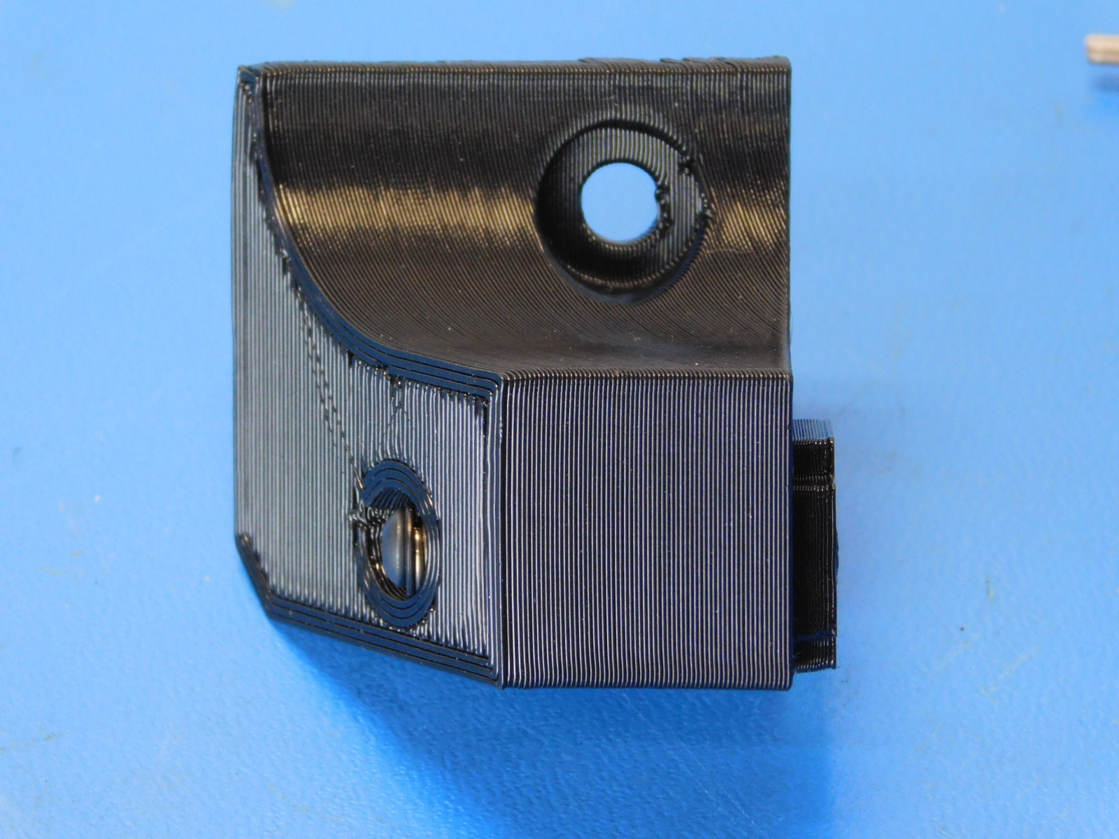
Insert into the Y Chain Pivot Mount [PP-GP0367] as shown
Place the Y Chain Pivot w/ Inserts [PP-IS0096] on the opposite side and thread fastener into insert.
There is no need to tighten it completely

Materials required for [AS-PR0123] Y-Motor Mount Assembly:
1x - [PP-FP0151] Y Endplate
1x - [PP-GP0362] Y Motor Mount
4x - [HD-BT0148] M3 x 10 Button Head Screw
4x - [HD-NT0001] M3 Nylon-Insert Locknut
4x - [HD-WA0038] M3 Black-Oxide Flat Washer
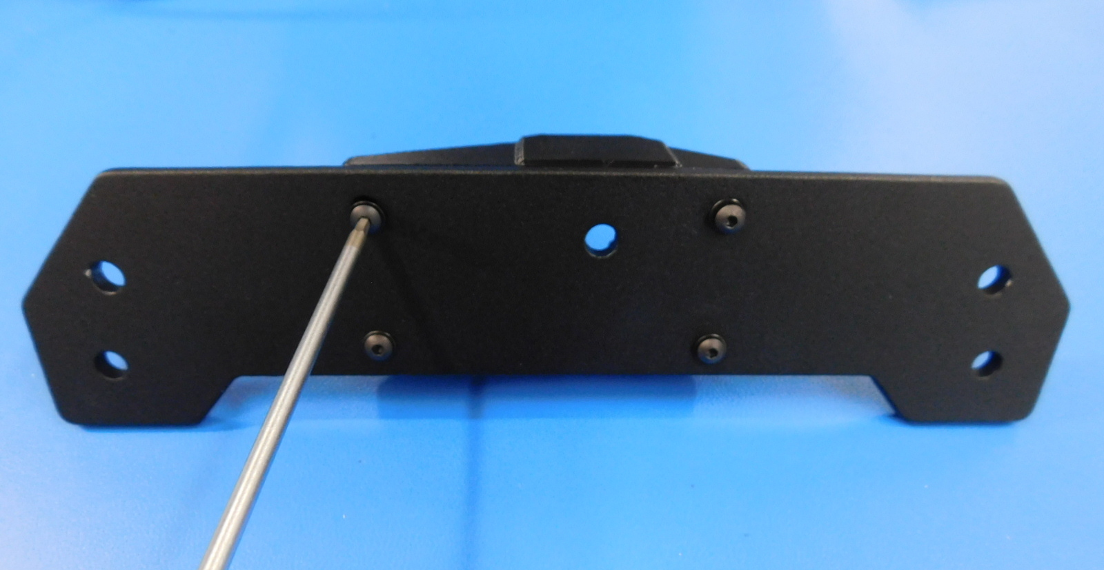
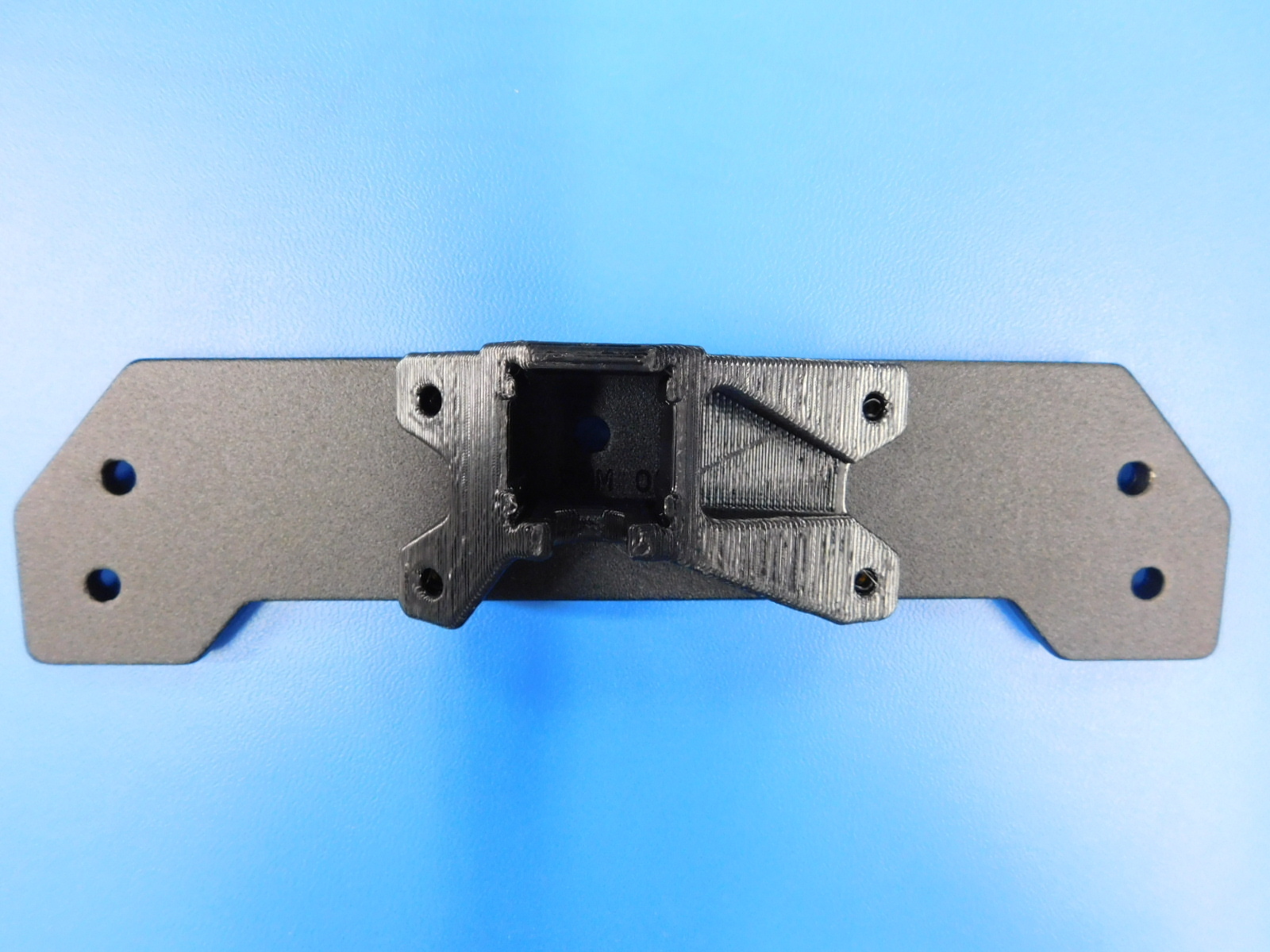
Secure the [PP-GP0362] Y-Motor Mount to the [PP-FP0151] Y-Endplate using 4x [HD-BT0148] M3 x 10 Bolts with 4x [HD-WA0038] M3 Washers, and insert 4x [HD-NT0001]** Nyloc Locknuts into the printed part to attach the Y-Motor Mount to the Y-Endplate. Note the correct part orientation.
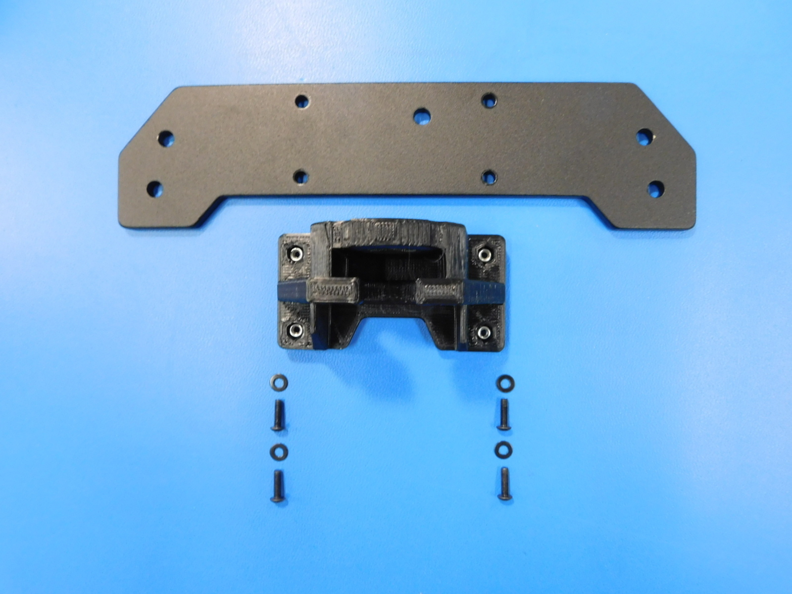
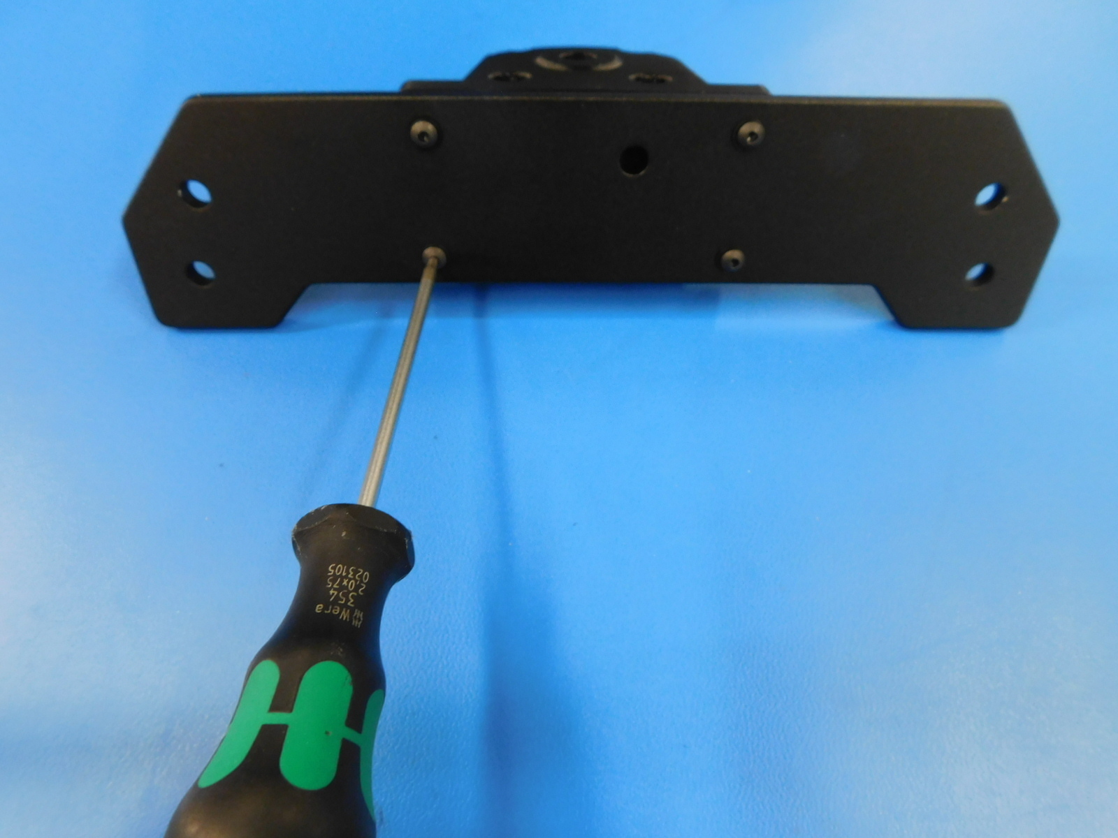
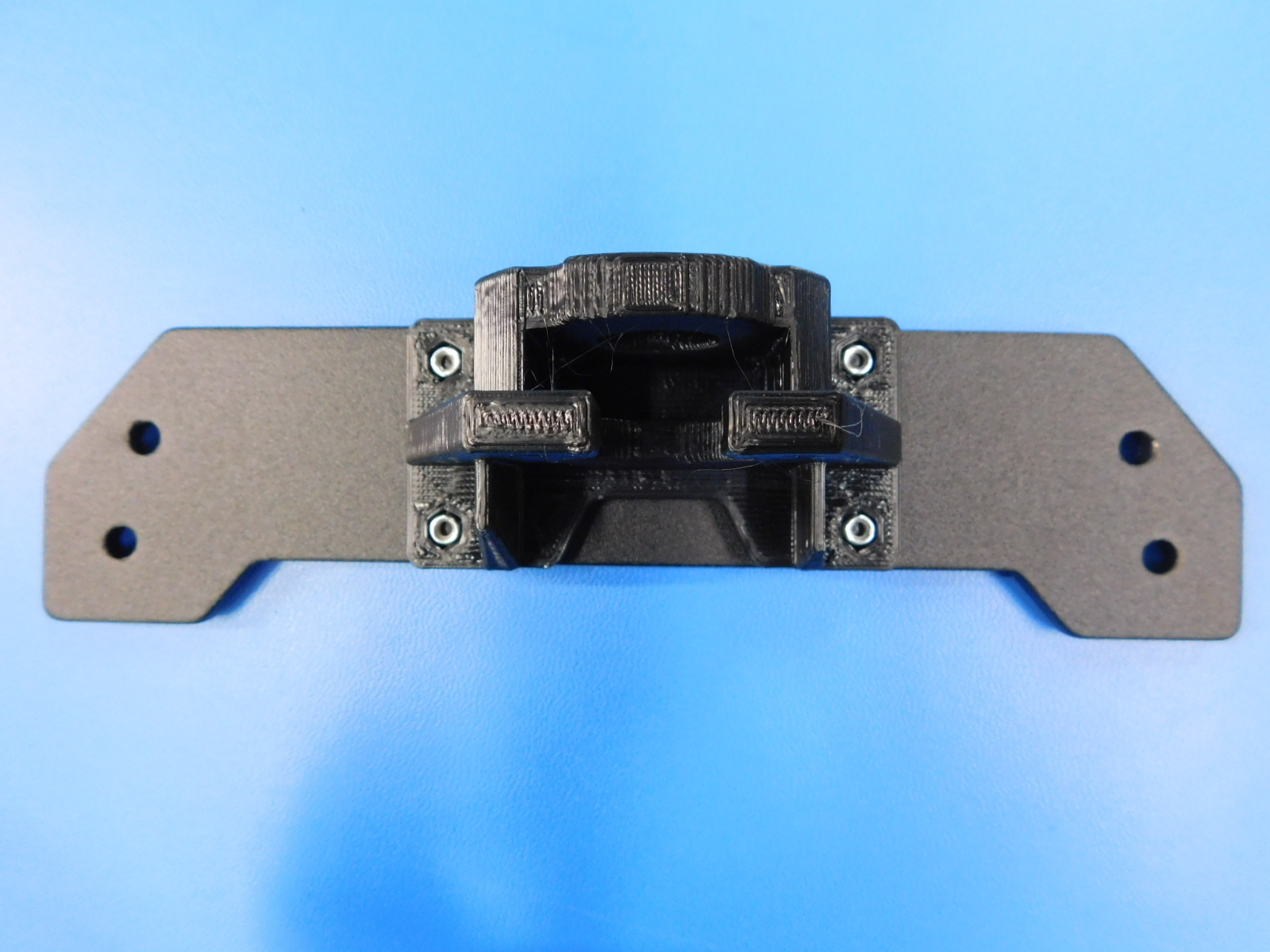
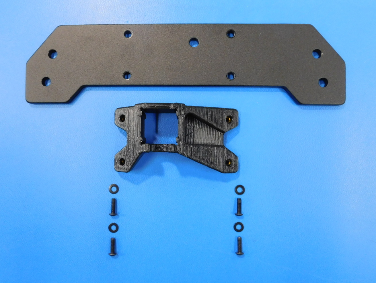
Materials required for [AS-PR0122] Y-Idler Mount Assembly:
1x - [PP-FP0151] Y Endplate
1x - [PP-IS0091] Y-Idler Housing with Inserts
4x - [HD-BT0148] M3 x 10 Button Head Screw
4x - [HD-WA0038] M3 Black-Oxide Flat Washer
Secure the [PP-IS0091] Y-Idler Housing with Inserts to the [PP-FP0151] Y-Endplate using 4x [HD-BT0148] M3 x 10 Bolts with 4x [HD-WA0038] M3 Washers. Note the correct part orientation.
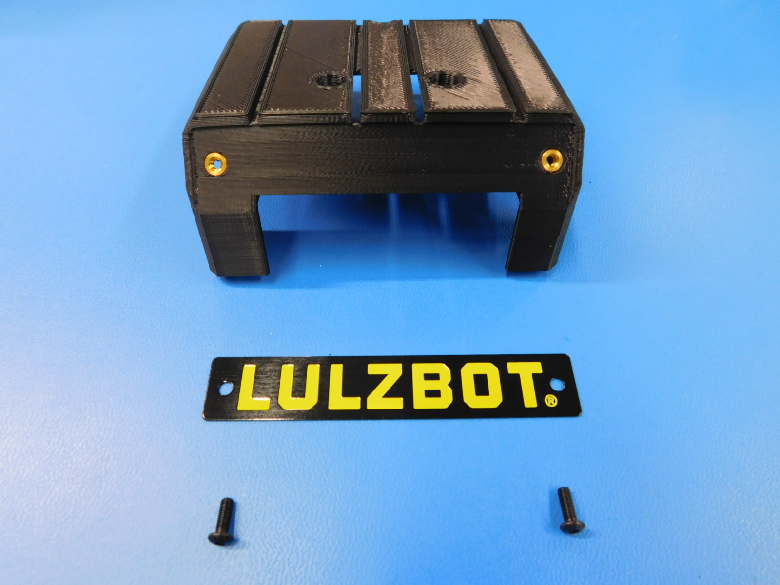
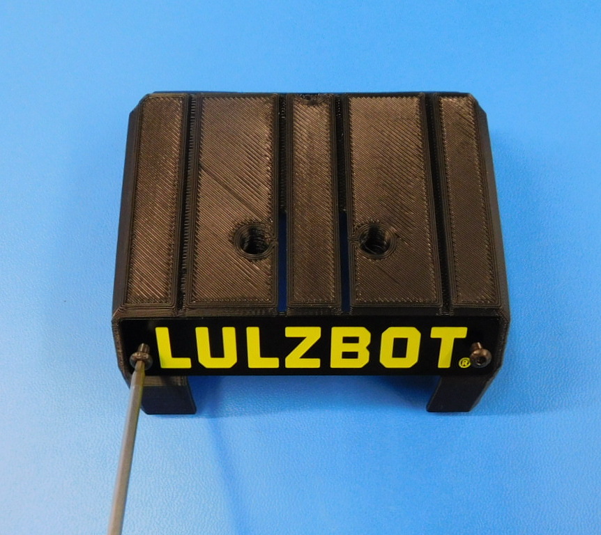
Materials required for [AS-PR0146] Extruder Cap with Plaque sub-assembly:
1x - [PP-IS0112] Extruder Cap with Inserts
1x - [DC-LB0176] LULZBOT Etched Toolhead Tag
2x - [HD-BT0137] M3 x 8 Bolt, BHCS, Black-Oxide
Secure the [DC-LB0176] LULZBOT Toolhead Tag to the [PP-IS0112] Extruder Cap with Inserts using 2 [HD-BT0137] M3 x 8 Bolts. Note the correct orientation in the image shown. Torque to 3in lbs