Open HardwareAssembly Instructions
Guides for installation and assembly of the LulzBot line of products made by Aleph Objects, Inc.
Guides for installation and assembly of the LulzBot line of products made by Aleph Objects, Inc.
[AS-PR0136] X-End Left Assembly, Taz Pro 1 PCE
[AS-PR0130] X-End Right Assembly, Taz Pro 1 PCE
[AS-PR0137] Spool Arm Assembly, Taz Pro 2 PCE
[AS-PR0138] Y Chain Pivot Assembly, Taz Pro 1 PCE
[AS-PR0150] T-Slot dust cover, cut, 285mm 1 PCE
[AS-PR0151] T-Slot Dust cover, cut, 522mm 1 PCE
[EL-HR0142] Z Endstop Harness, Assembled 1 PCE
[PP-IS0097] Z-Chain Mount with Inserts, Taz Pro 1 PCE
[PP-IS0098] Bed Mount Chassis with Insert, Taz Pro 4 PCE
[HD-BT0049] Metric Class 12.9 Socket Head Cap Screw, Alloy Steel, M5 thread, 14MM length, 0.80MM pitch 2 PCE
[HD-BT0073] Class 10.9 Stl Button Head Socket Cap Screw M5 Size, 10 Mm Length, .8 Mm Pitch 80 PCE
[HD-BT0225] 316 Stainless Steel Button Head Hex Drive Screws, M5 x 0.8mm Thread, 10mm Long 1 PCE
[HD-EX0062] T-Slot Aluminum Frame TPW, Extrusion 20mm x 20mm x 500mm,Tapped M5x0.8 on Both Ends, Black (Ends free of anodize) 4 PCE
[HD-EX0086] T-Slot Extrusion, Aluminum, 20mm x 20mm, 20.866" 530mm 4 PCE
[HD-EX0090] 90 degree Corner Bracket 2 Hole 20mm Slotted Inside Corner Bracket with Dual Support for 20 Series 8 PCE
[HD-EX0092] 2 Hole Inside Corner Bracket For 20 Series 1 PCE
[HD-NT0044] Post assembly M5 T-nut 3 PCE
[HD-NT0053] T-Slot Slide in T-nuts for Aluminum Frame, M5 73 PCE
[HD-WA0007] M5 Washer, Steel, Zinc Plated 1 PCE
[HD-WA0040] Black-Oxide 18-8 Stainless Steel Flat Washer, M5 Screw Size, 5.3mm ID, 10.0mm OD 82 PCE
[PP-FP0152] Corner Bracket 8 PCE
[PP-GP0409] Frame Foot, Taz Pro 4 PCE
[PP-GP0410] Electronic Chassis Mount-Front, Taz Pro 1 PCE
[PP-GP0411] Electronic Chassis Mount-Back, Taz Pro 2 PCE
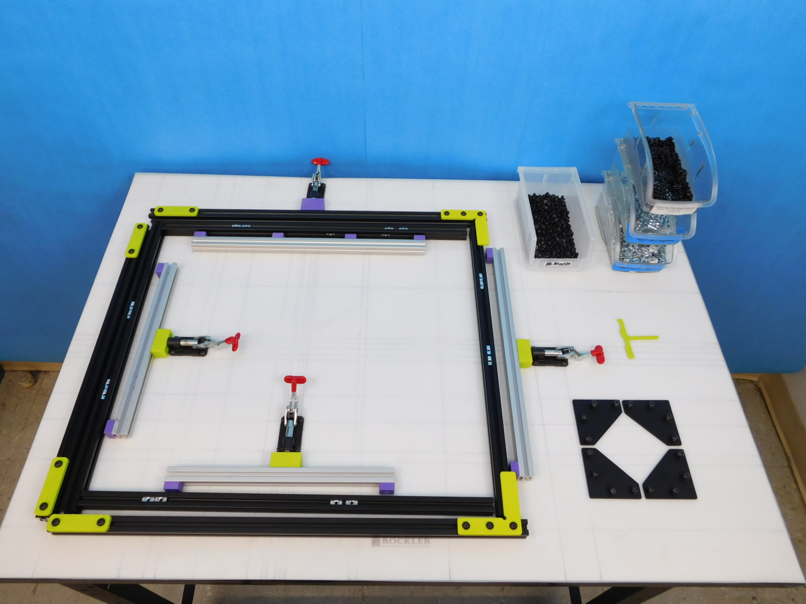
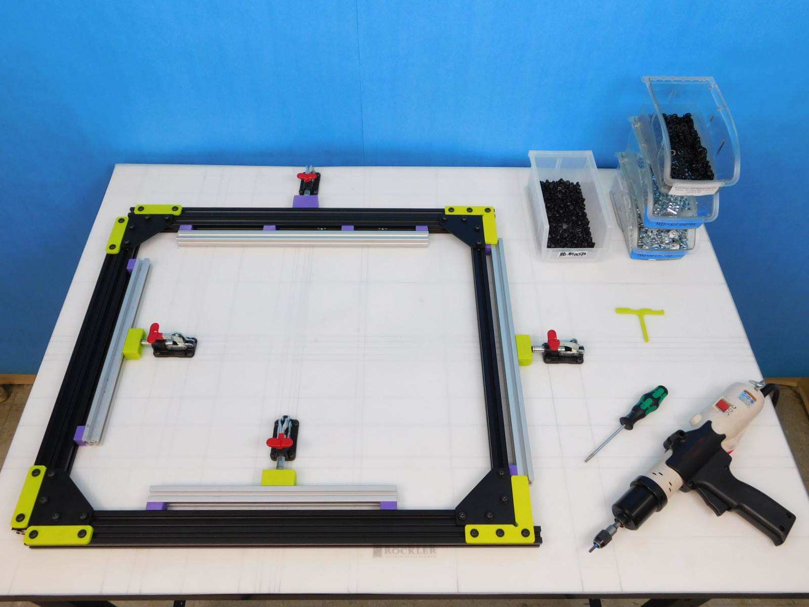
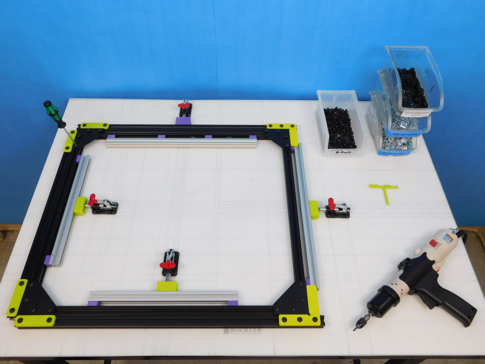
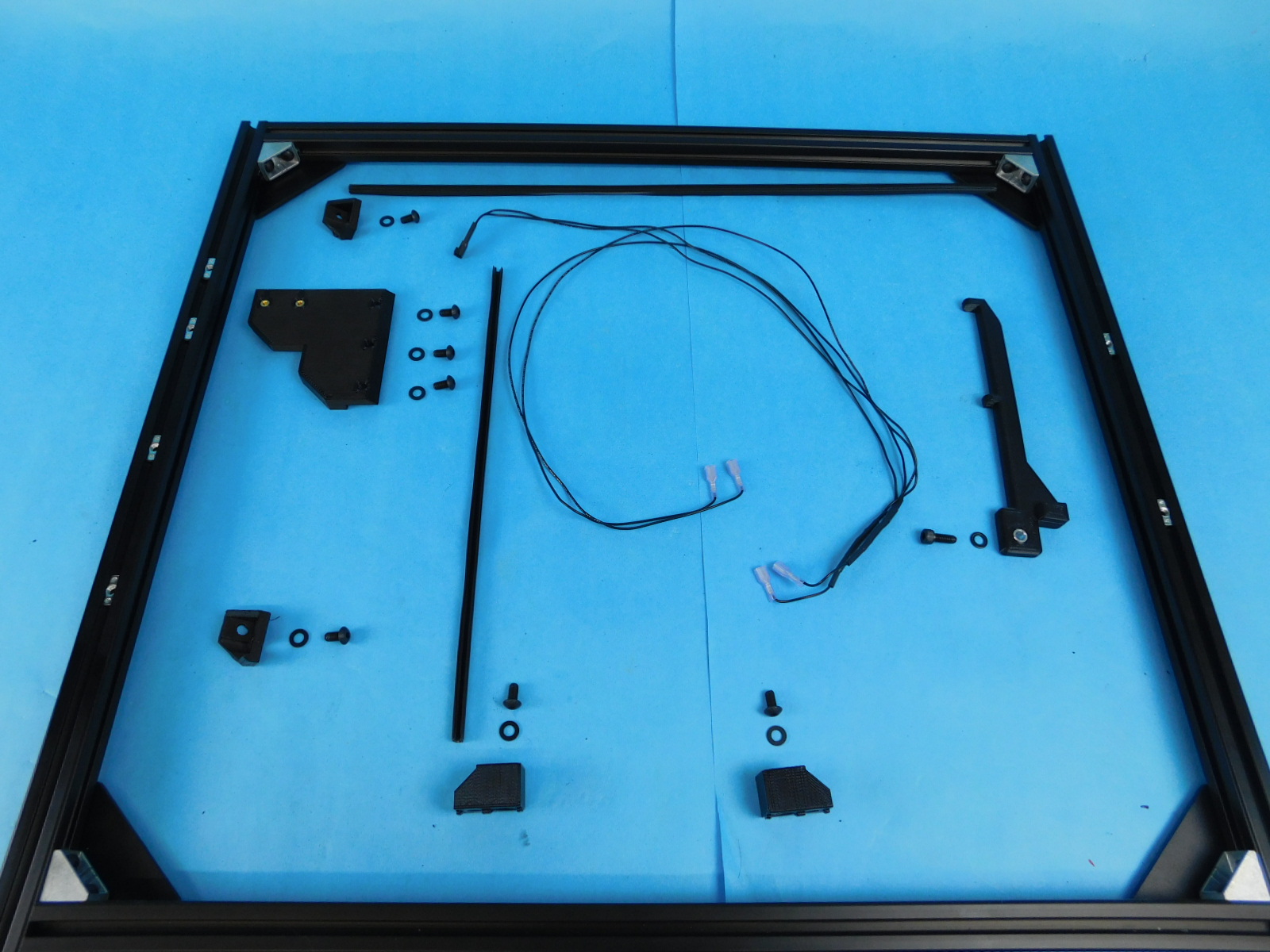
Place the t-nuts in the locations according to the drawing.
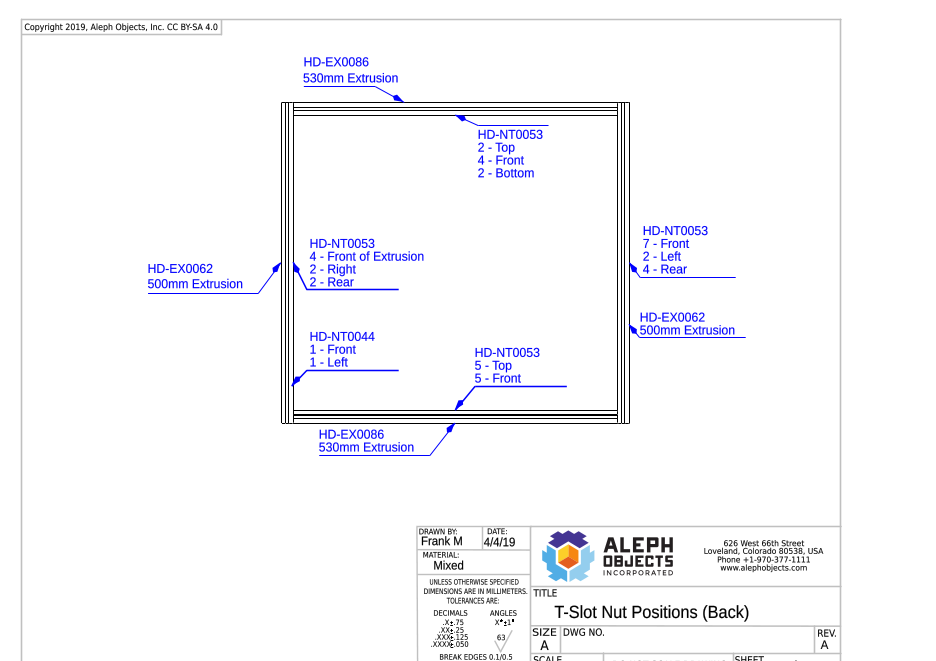

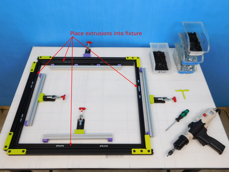
Place 2X [HD-EX0062] 500mm extrusions in the vertical slots and 2X [HD-EX0086] 530 extrusions in the horizontal slots.
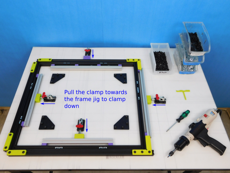
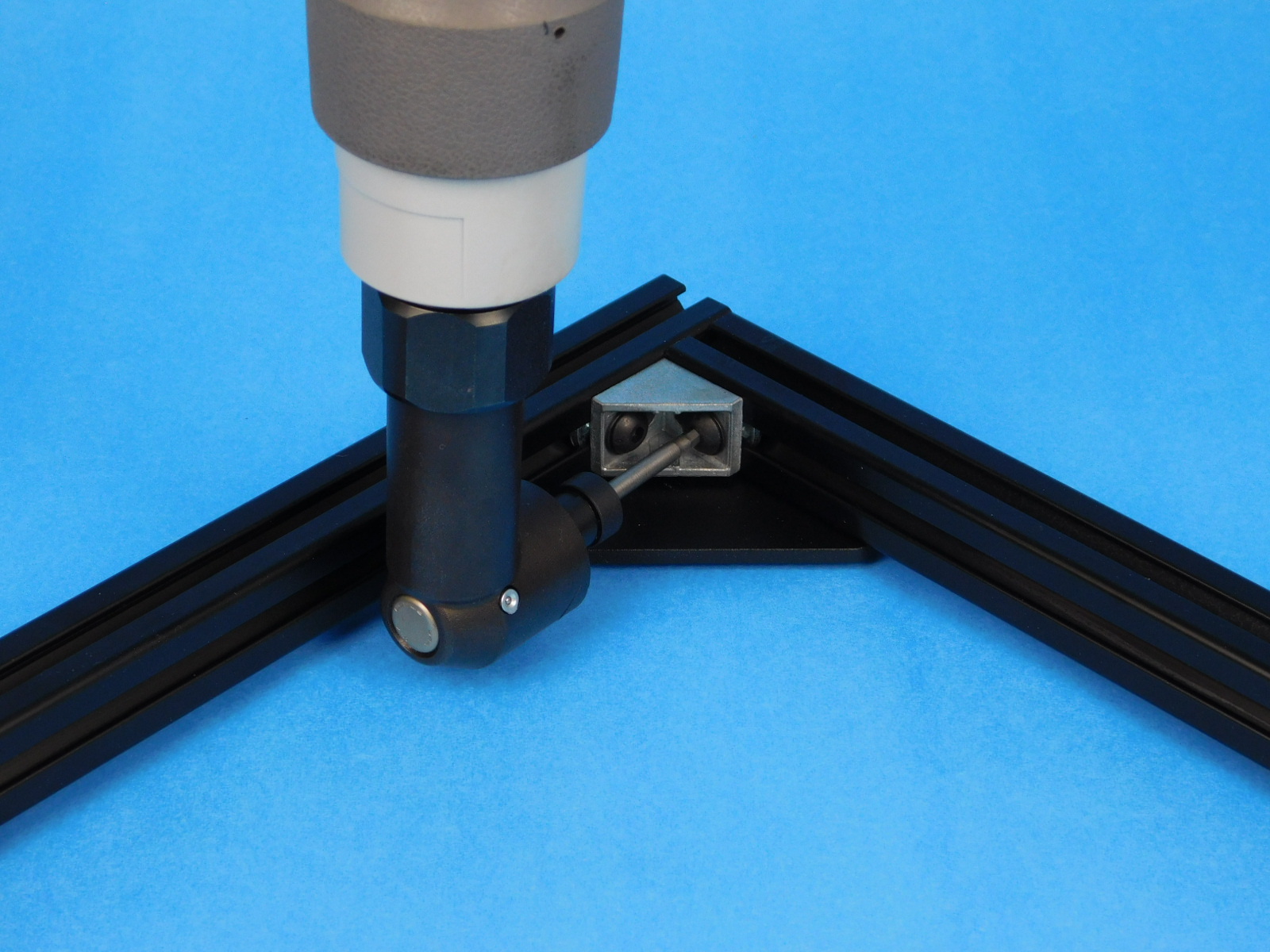
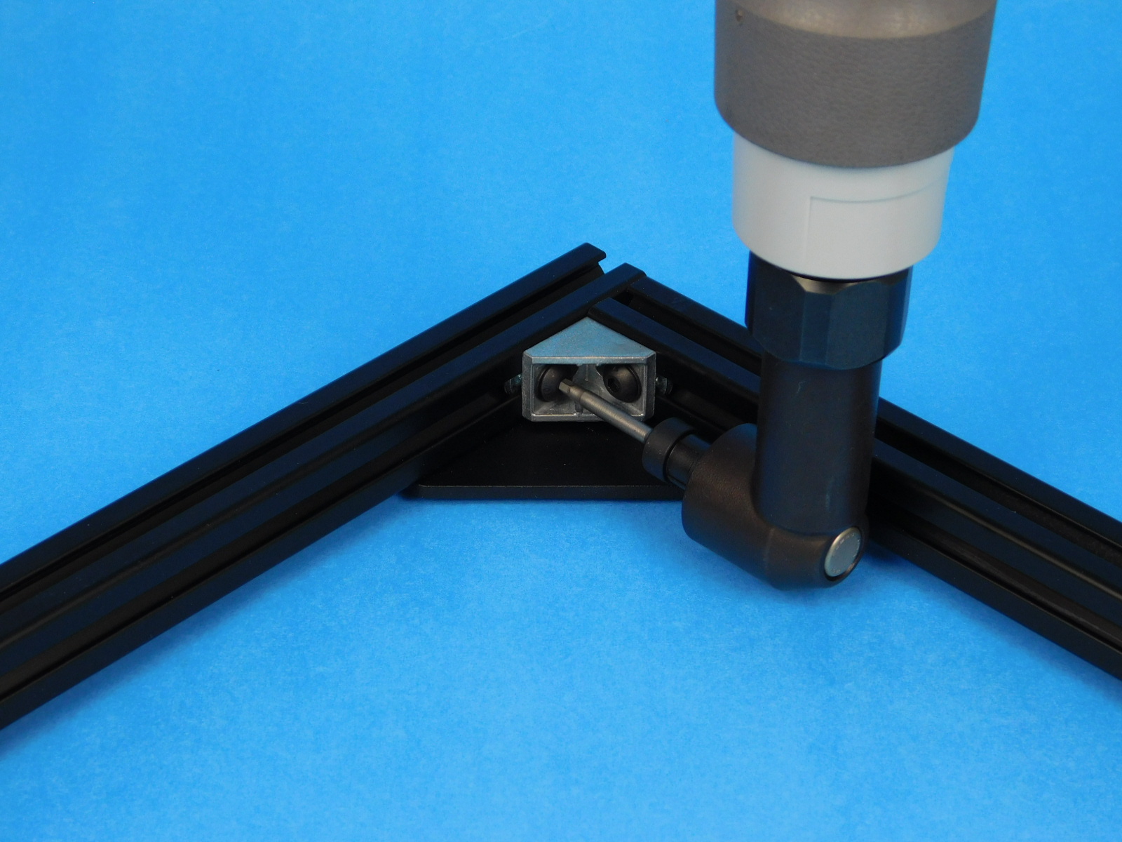
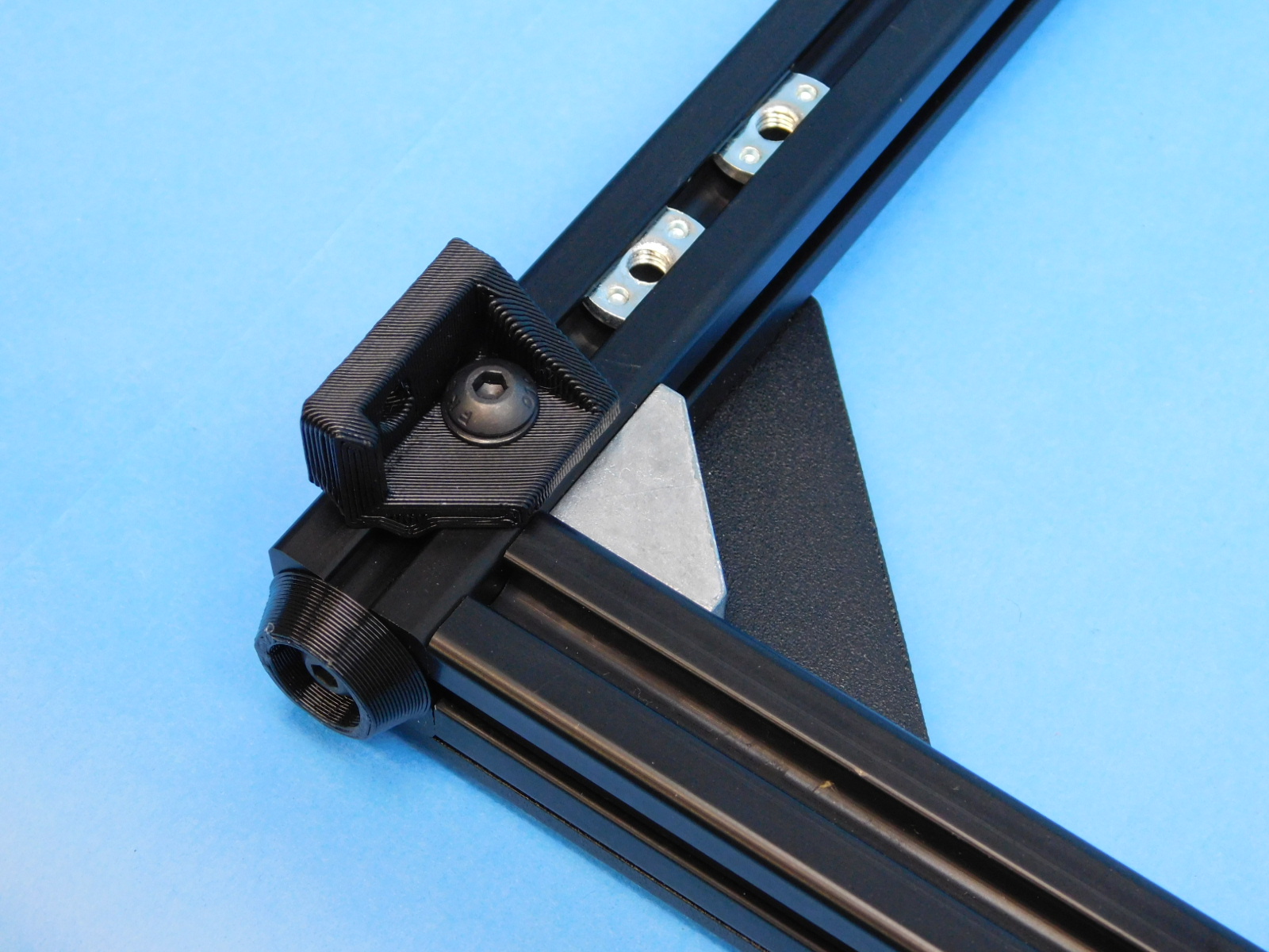
To clamp the frame into place, pull the handle towards the extrusions.
Utilize the t-nut alignment jig to align the t-nuts in preparation for installing the [PP-FP0152] frame corners.
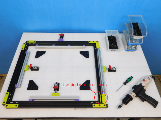
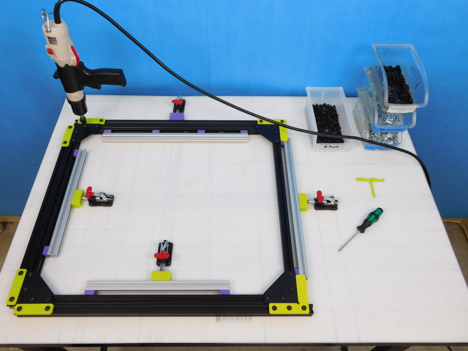
Align the 4X [PP-FP0152] frame corners with the t-slot nuts on each corner.
Fasten each [HD-FP0152] frame corner to the frame by hand, using 16X [HD-BT0073] M5X10 BHC fasteners.
Torque each [HD-BT0073] M5X10 BHC fastener to 40 in*lbs.
Remove the frame from the jig and repeat for the back face of the final assembly.
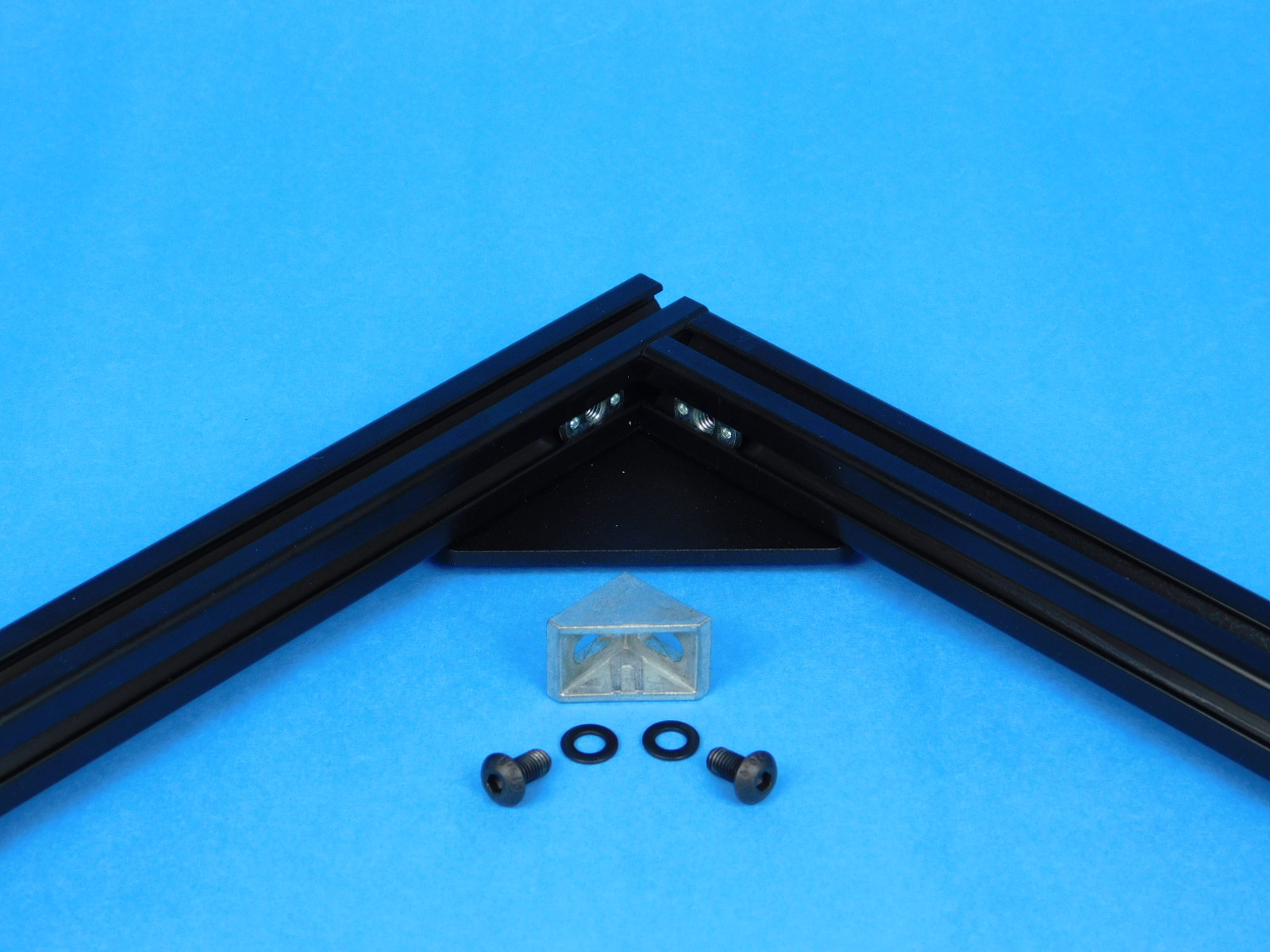
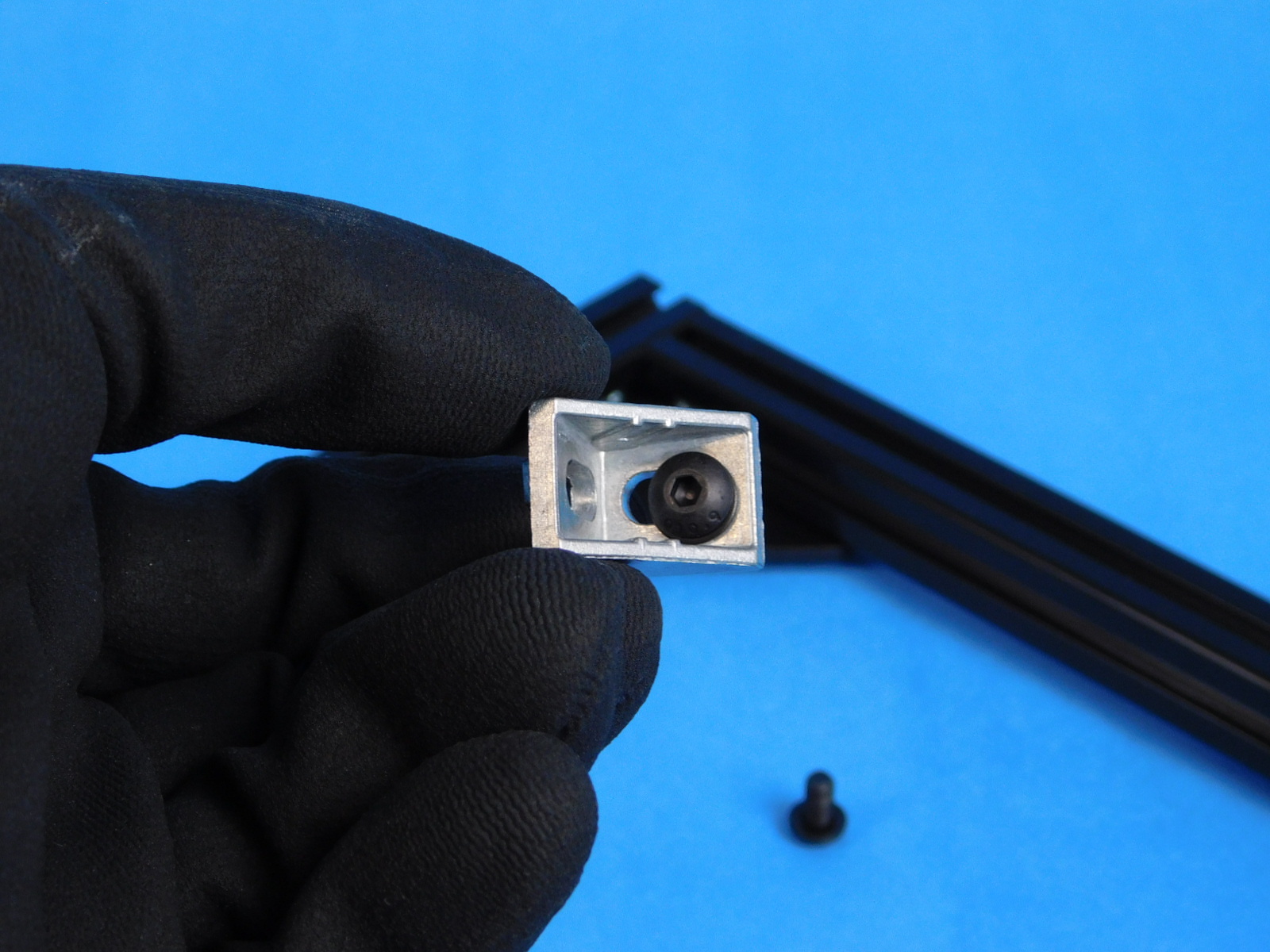
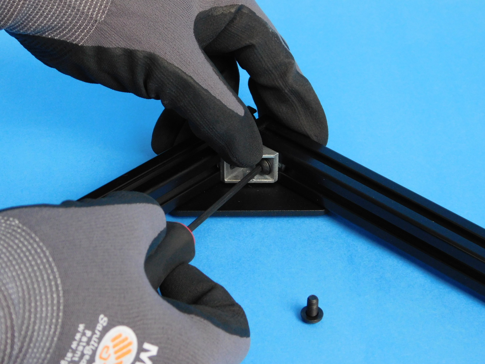
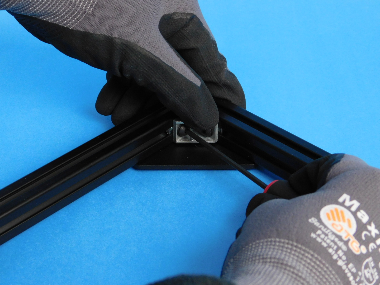
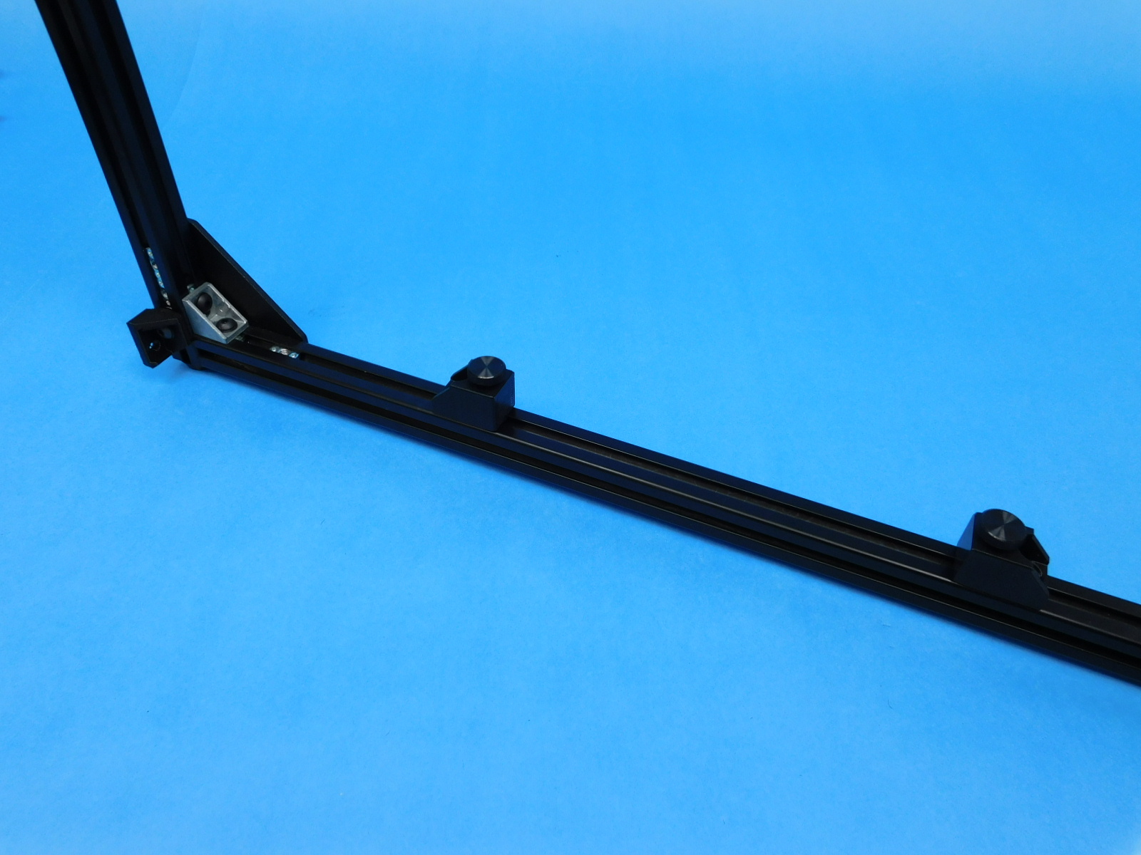
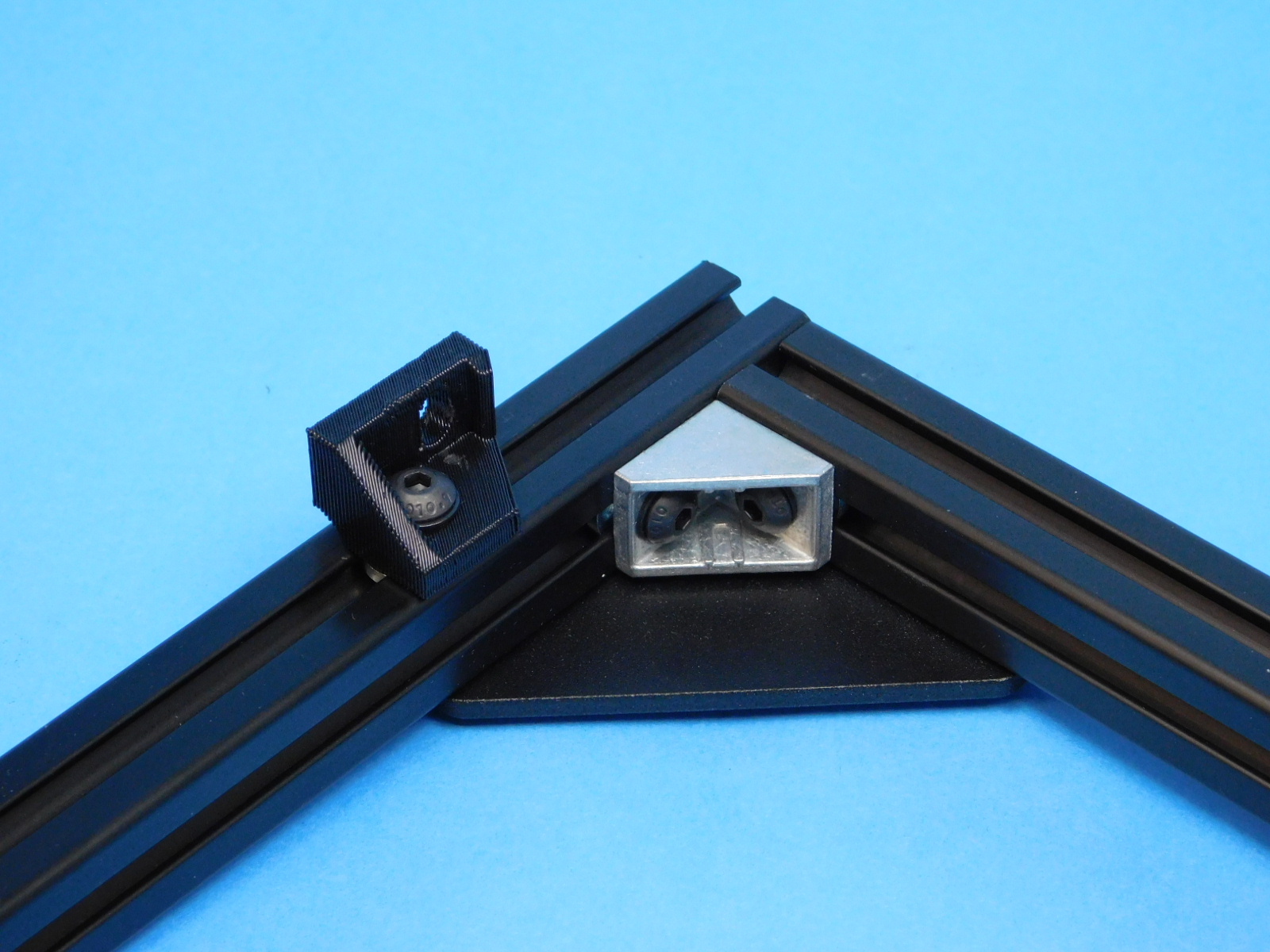
Take one 90 degree corner bracket [HD-EX0090], two M5 x 10 BHCS [HD-BT0073] and two M5 washers [HD-WA0040]. Attach one to each inside corner of the front and rear frame as shown.
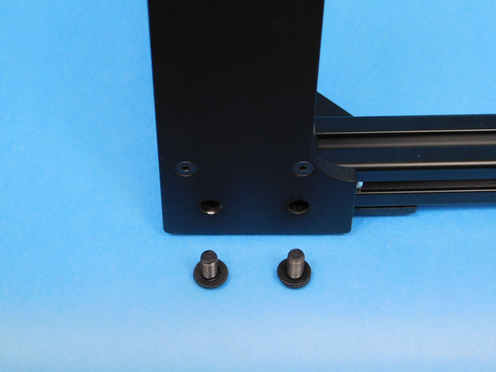
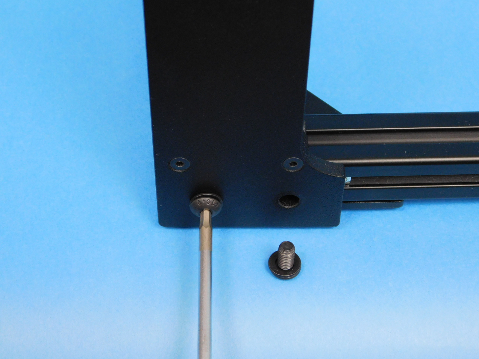
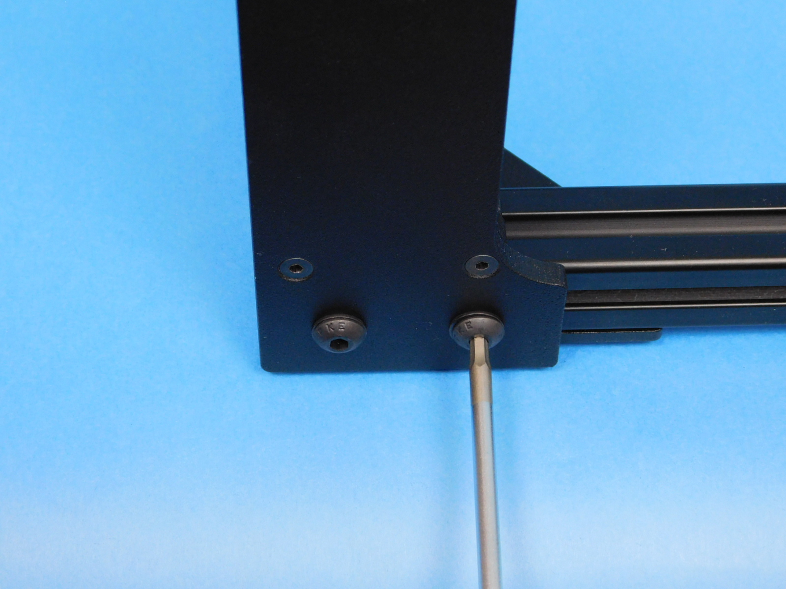
Using two [HD-BT0073] M5x10 BHCS and two [HD-WA0040] M5 black oxide washers, fasten the [PP-GP0409] frame feet to the threaded holes in the bottom of the frame assembly.
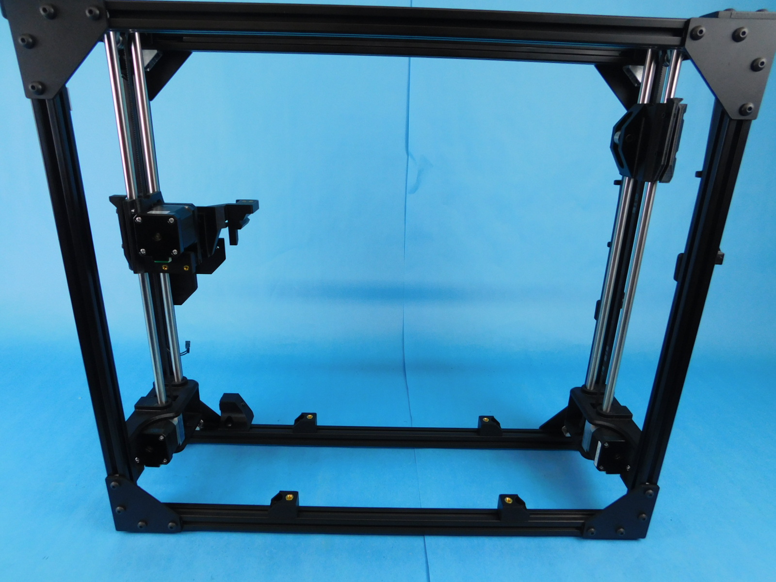
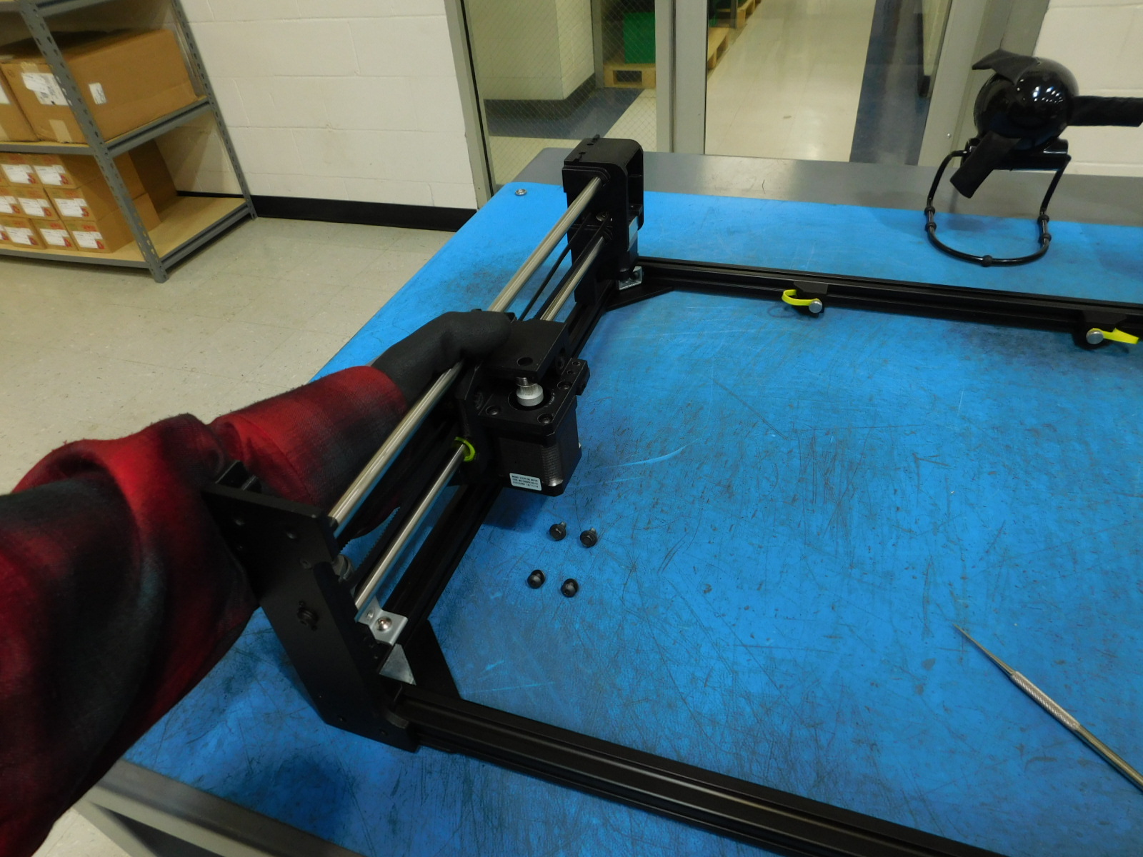
Using one [HD-BT0049] M5x14 SHCS and one [HD-WA0040] M5 black oxide washer, fasten the [AS-PR0137] spool arm assembly to the post assembly nut on the photo left side of the frame. This can be left loose at this time.
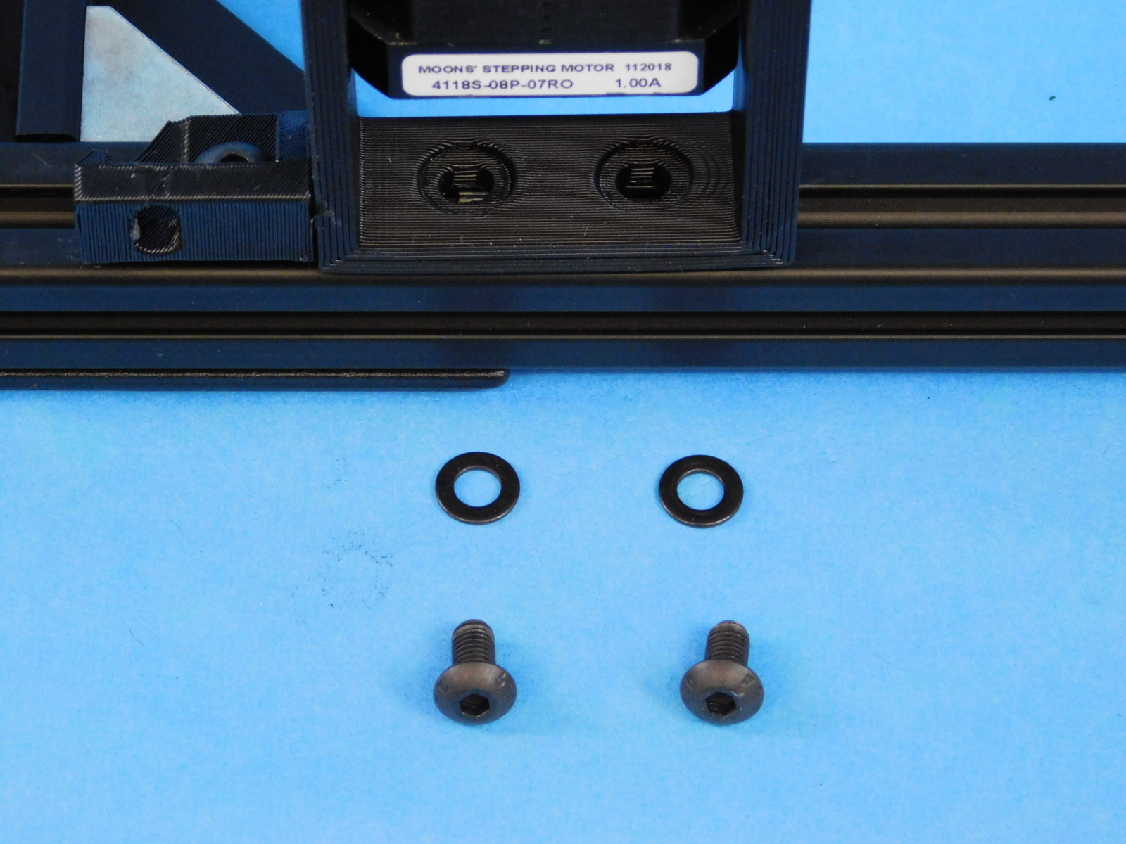
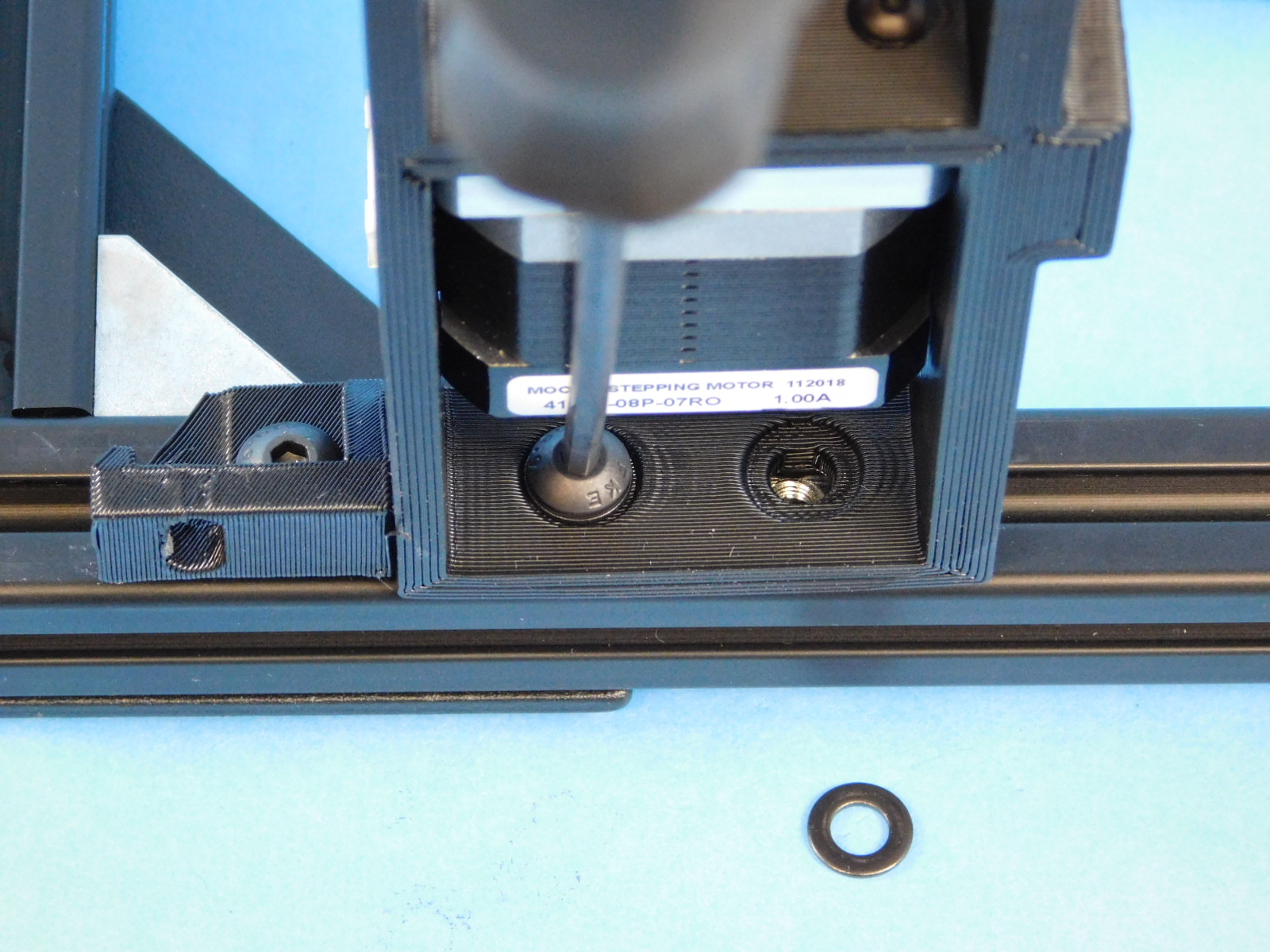
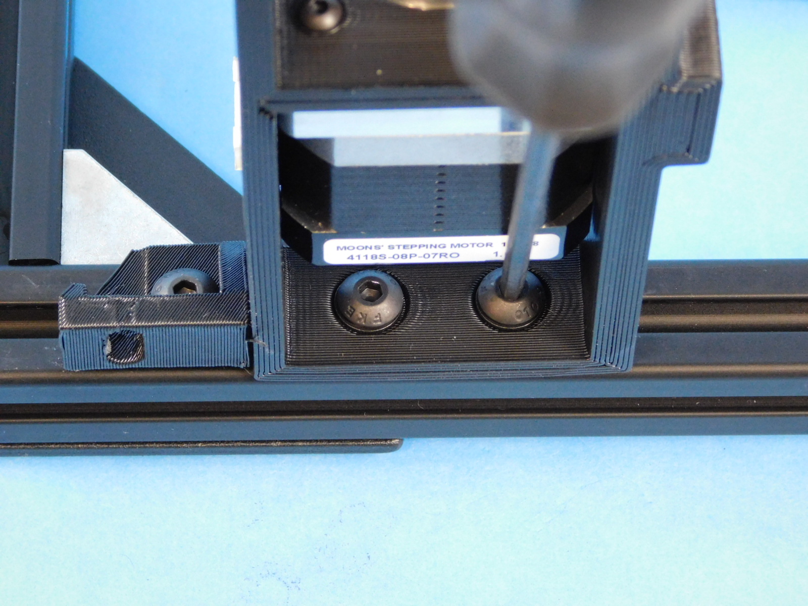
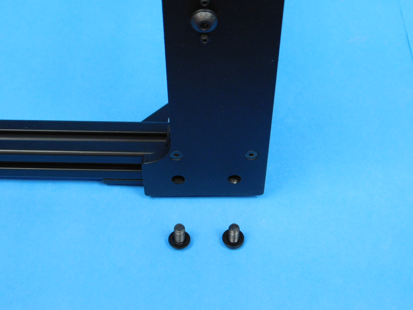
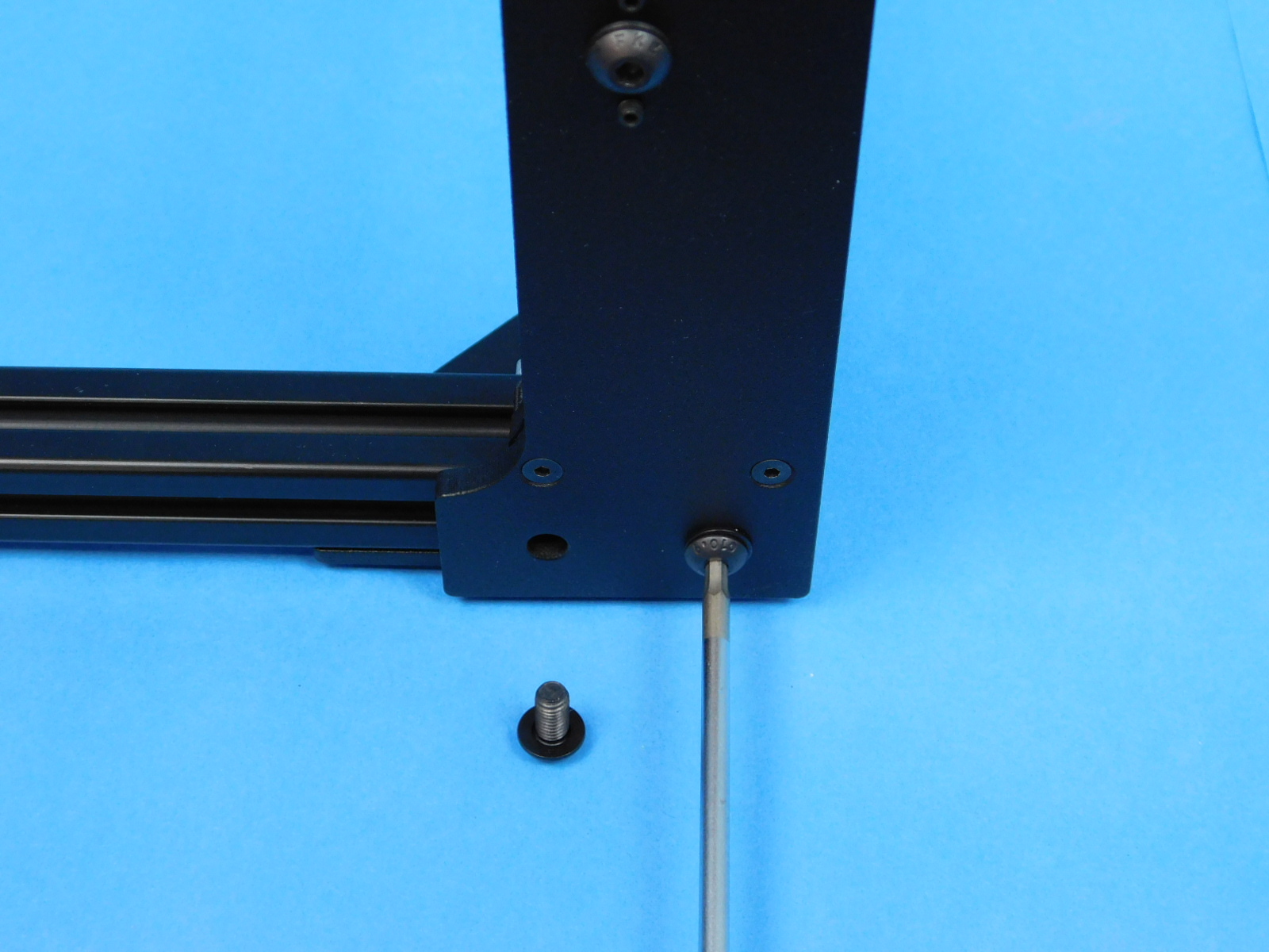
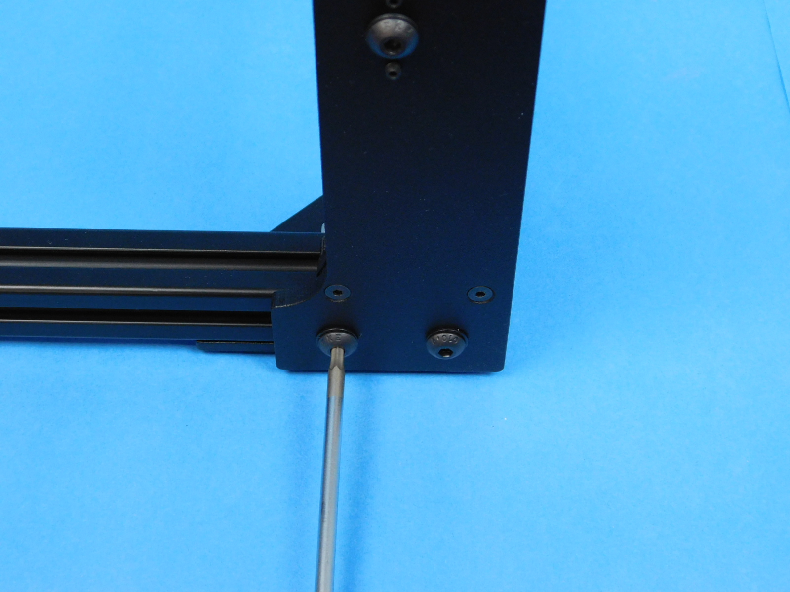
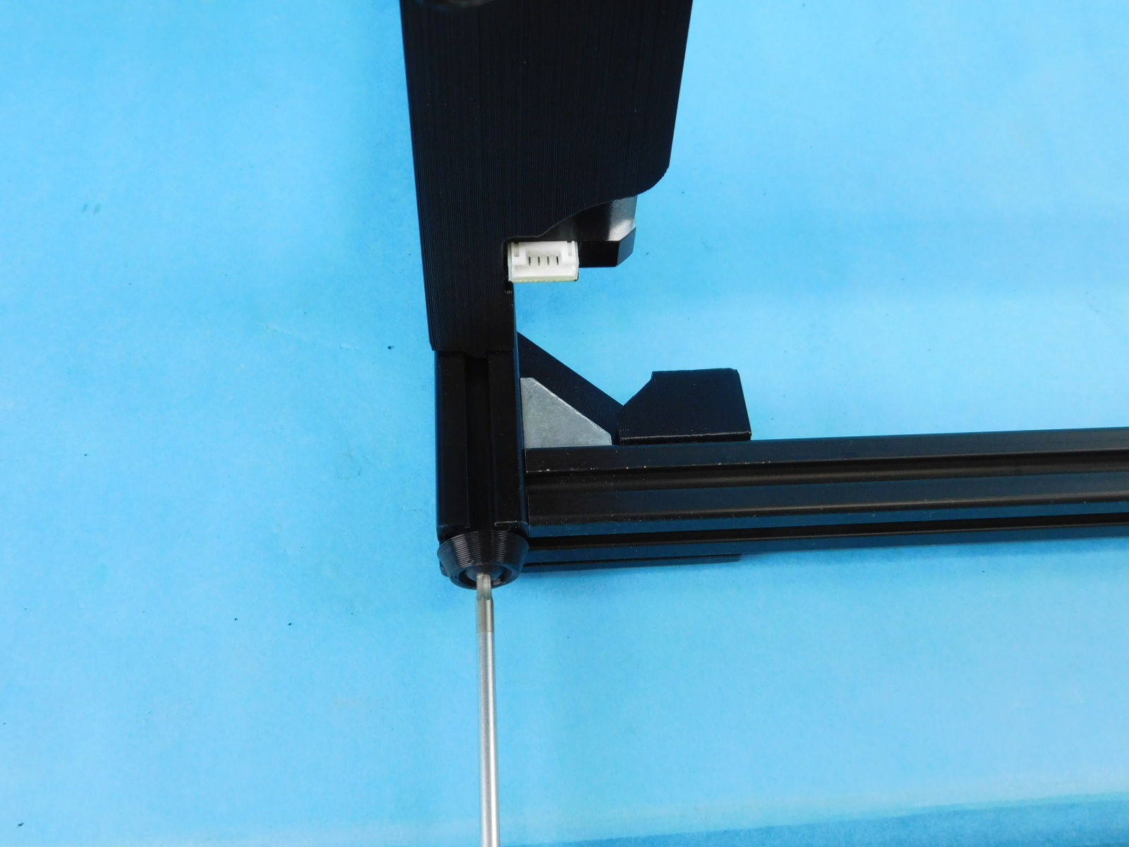
Using one [HD-BT0073] M5x10 BHCS and one [HD-WA0040] M5 black oxide washer, fasten the [PP-GP0410] front electronics chassis mount to bottom most t-slot nut on the photo right side of the frame.
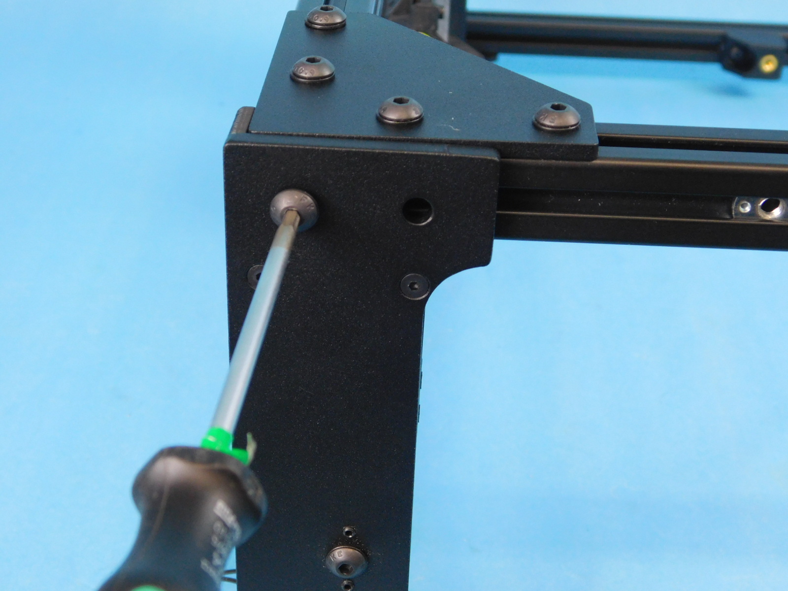
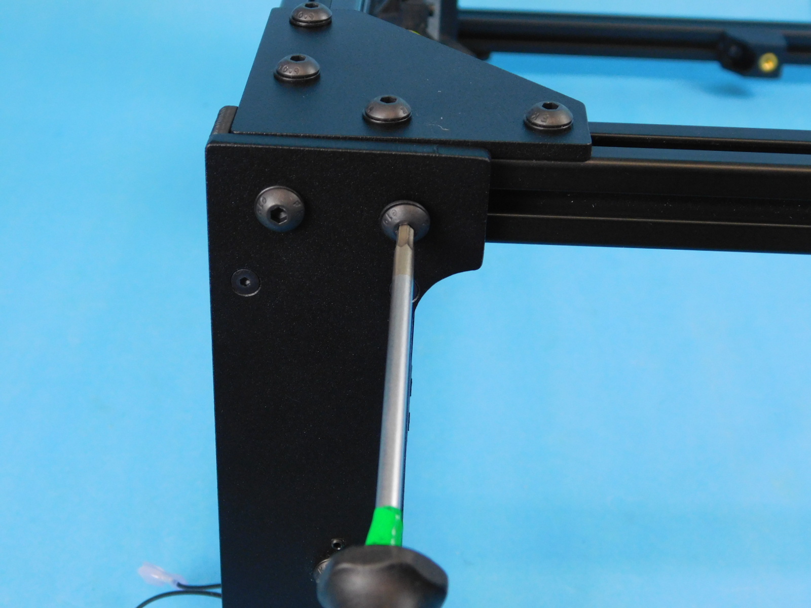
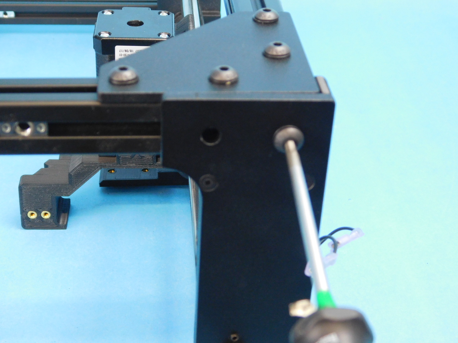
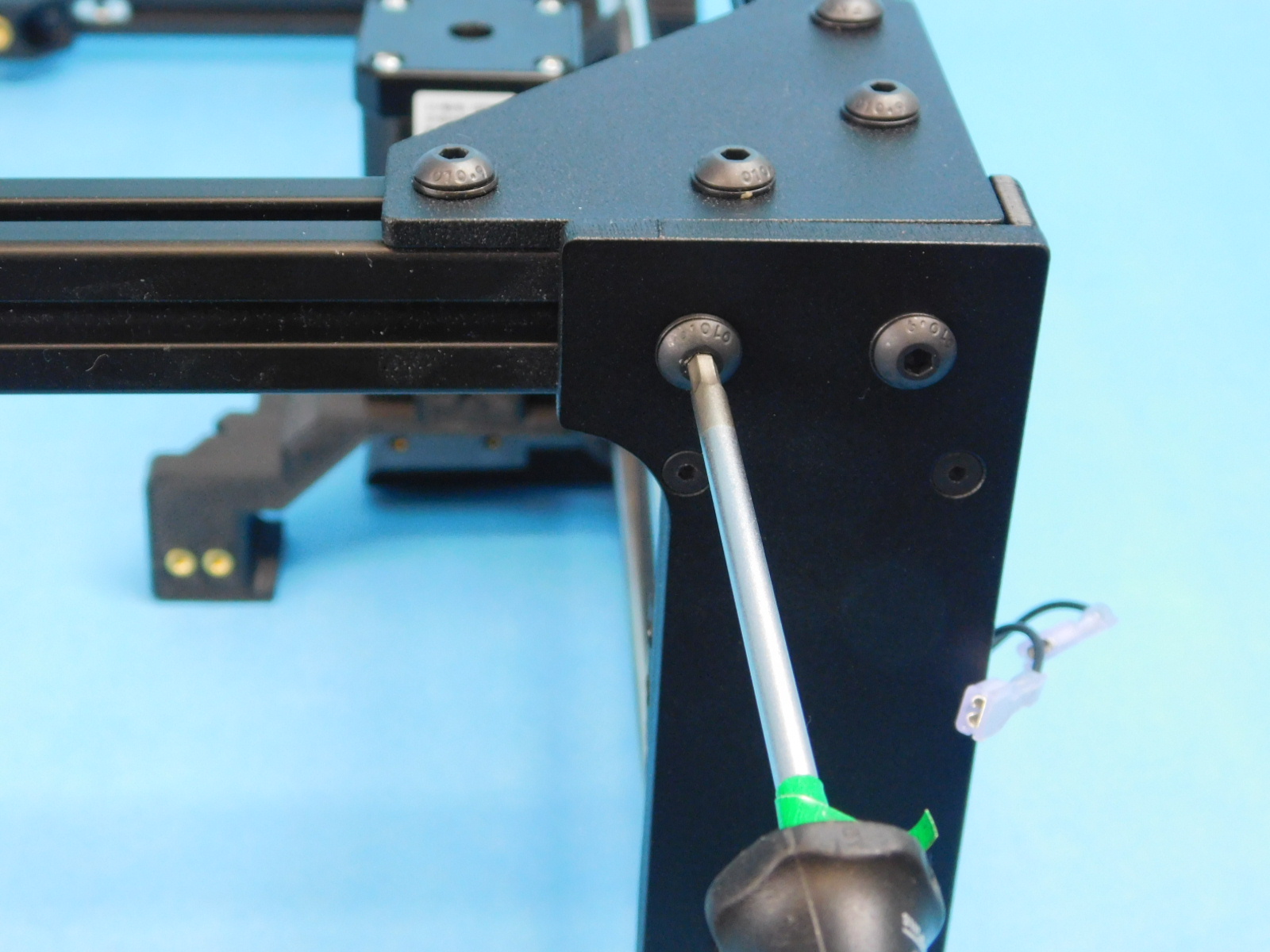
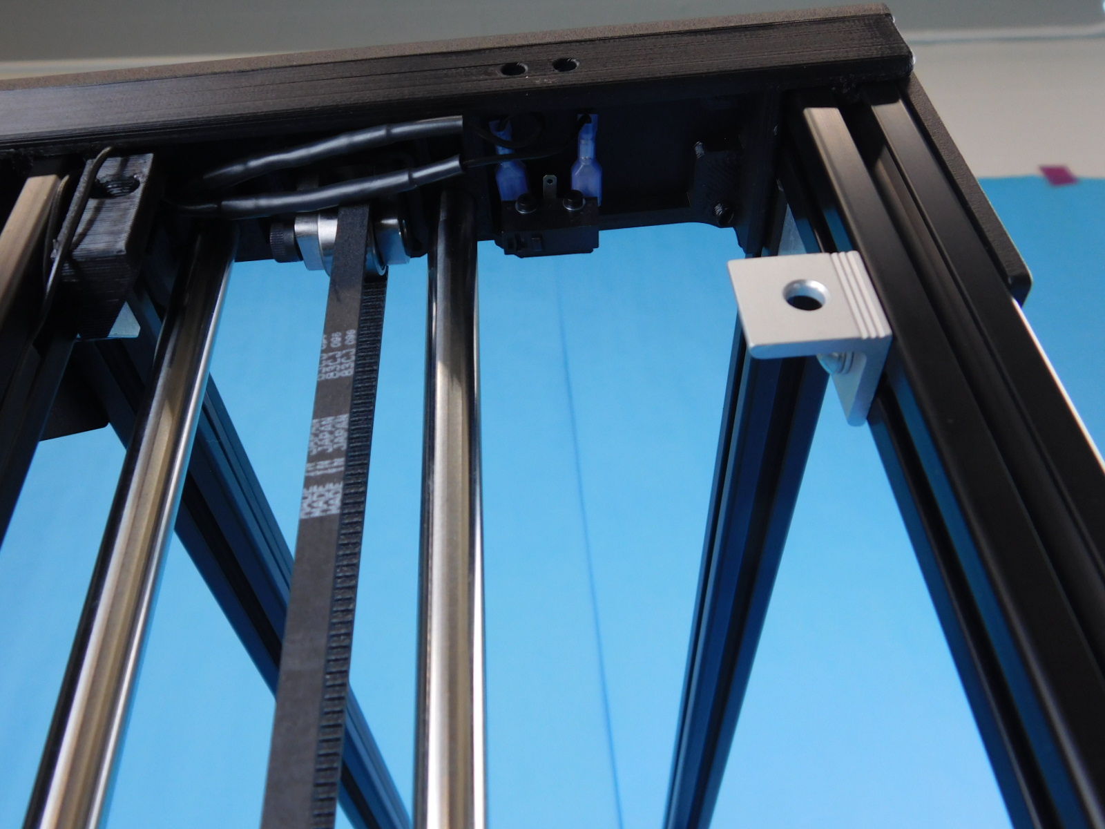
Using one [HD-BT0225] M5x10 stainless steel BHCS and one [HD-WA0007] M5 stainless washer, fasten the [HD-EX0092] aluminum corner bracket to the top most t-slot nut on the photo right side of the frame.
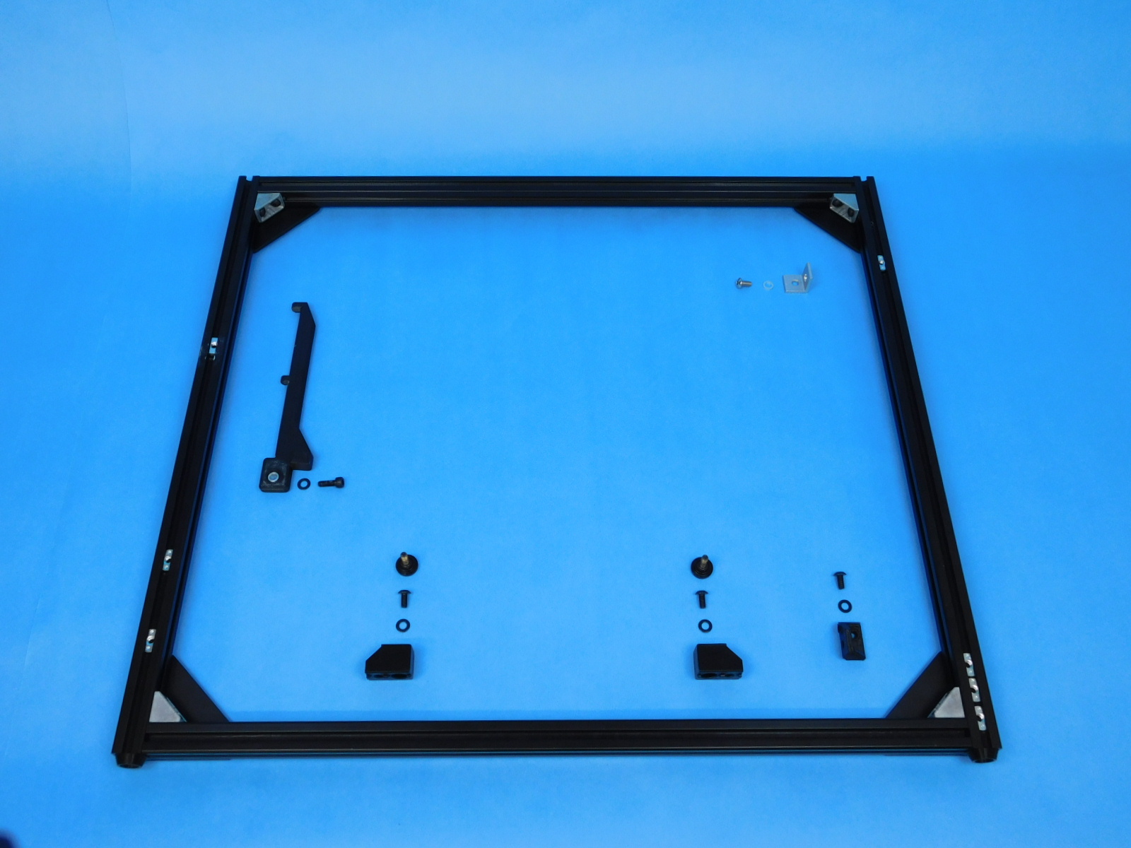
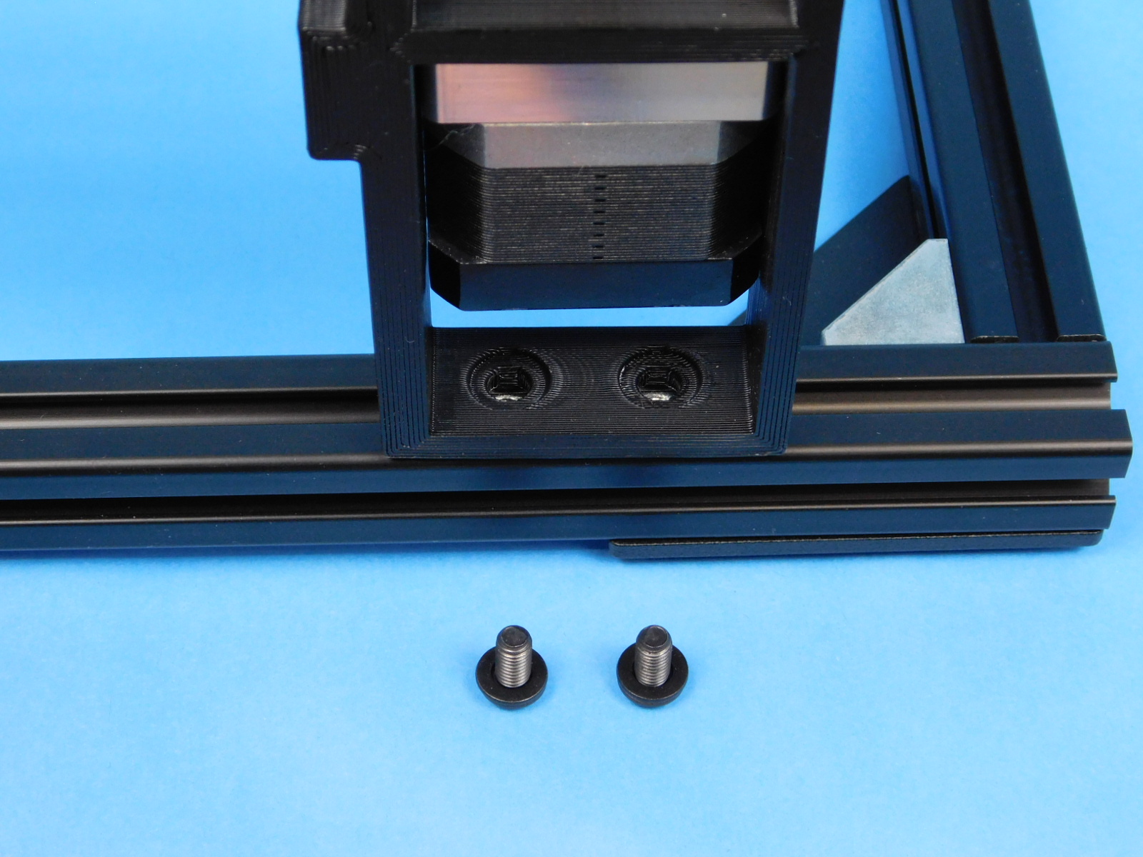
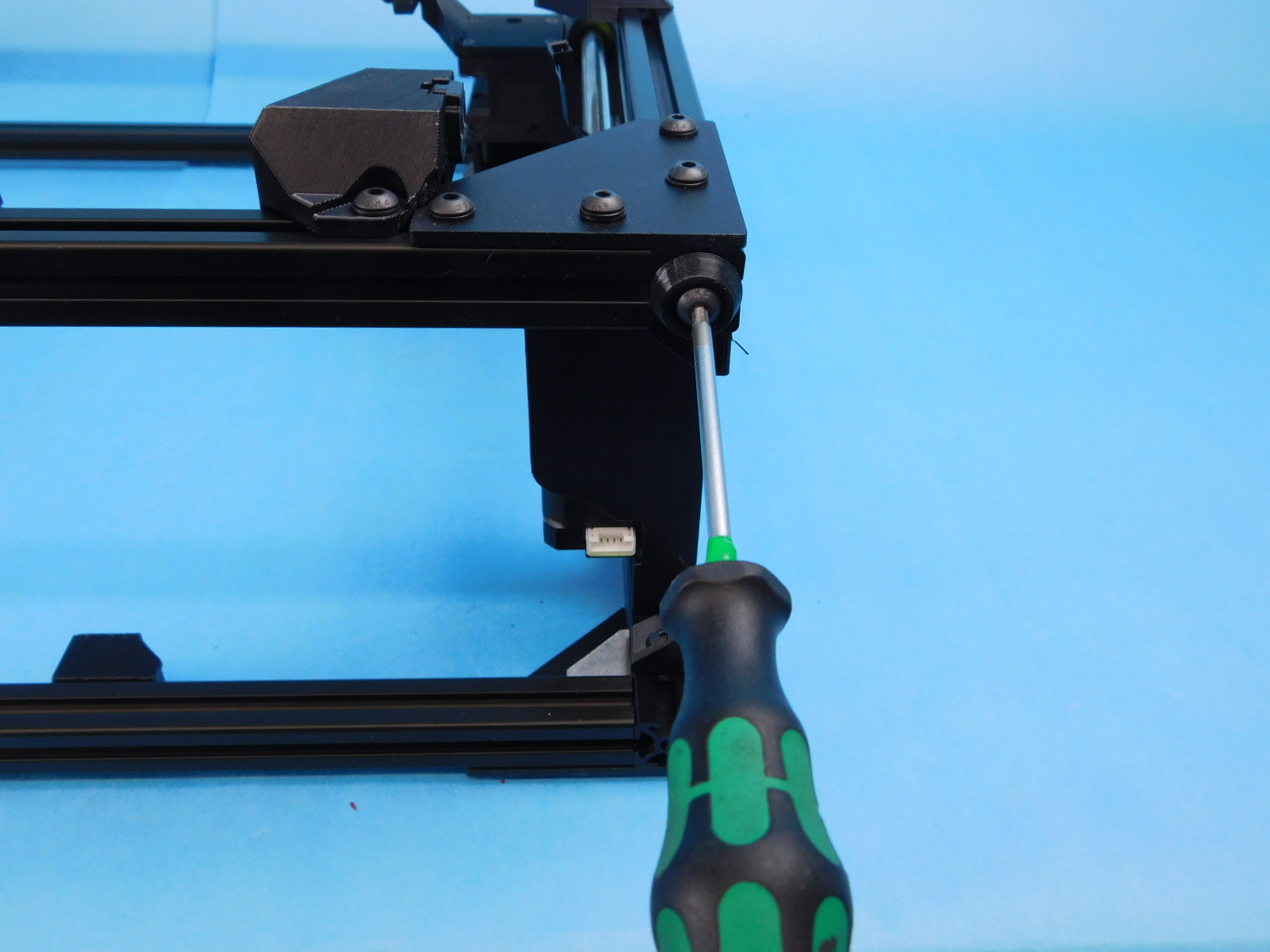
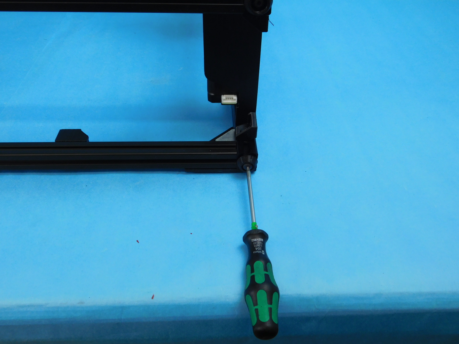
Using two [HD-BT0073] M5 x 10 BHCS and two [HD-WA0040] M5 washer, attach the [PP-GP0411] back chassis mount to the frame.
Use two [HD-BT0073] M5 x 10 BHCS and two [HD-WA0040] M5 washer, attach the [PP-IS0098] Y-Mount Chassis to the frame. Make sure to have one t-nut to the left of the chassis mounts.
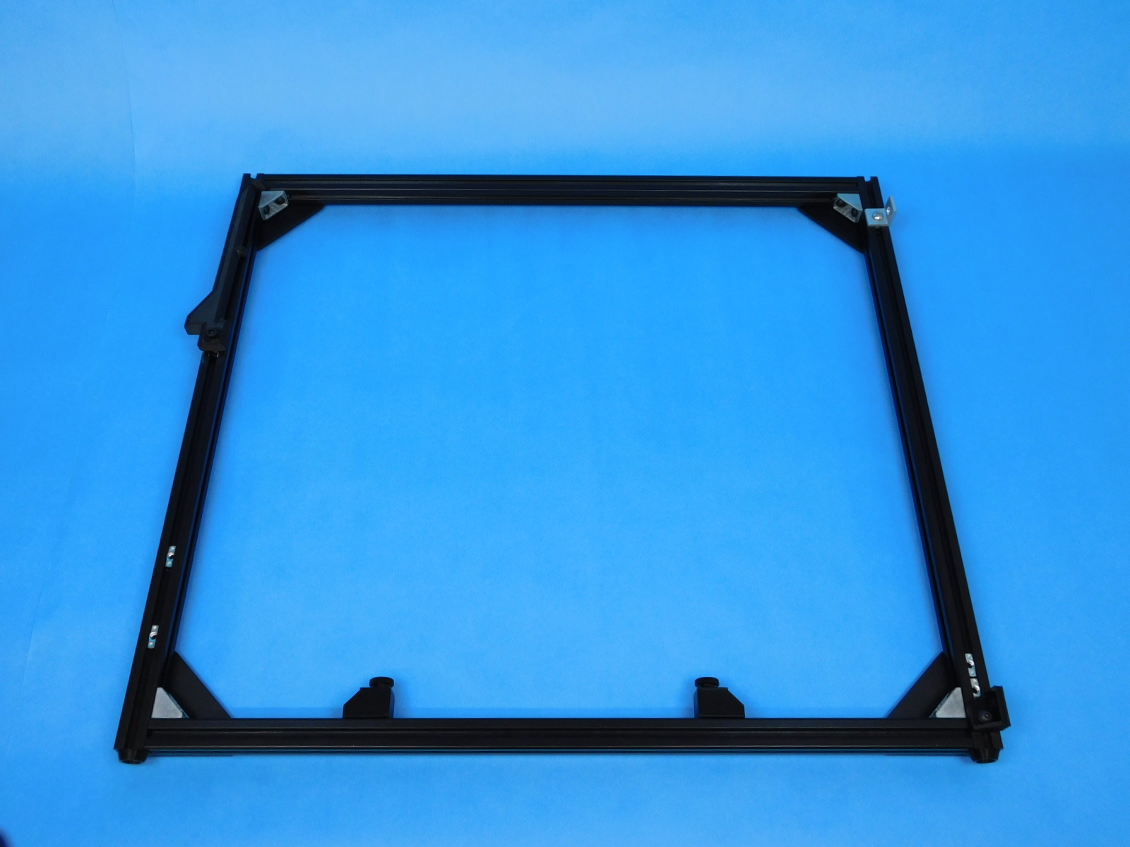
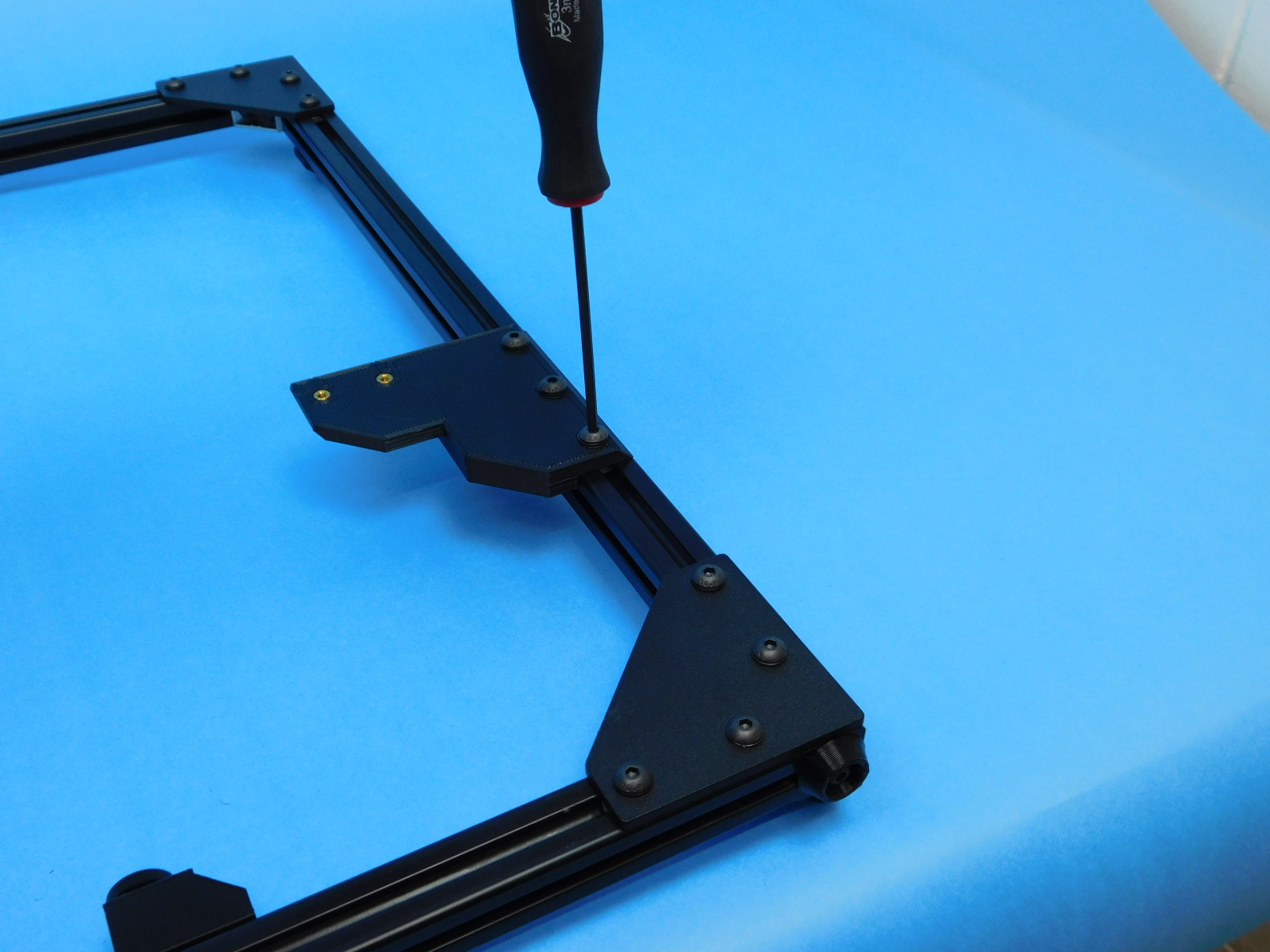
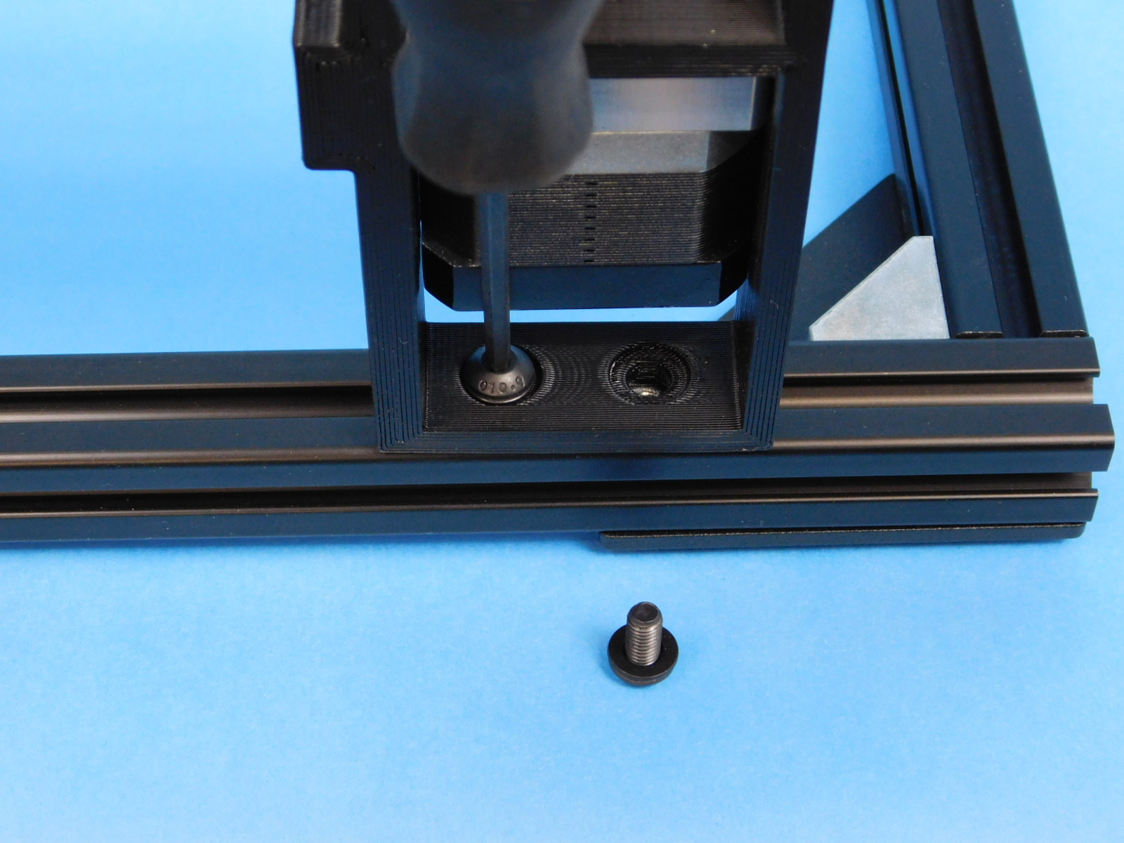
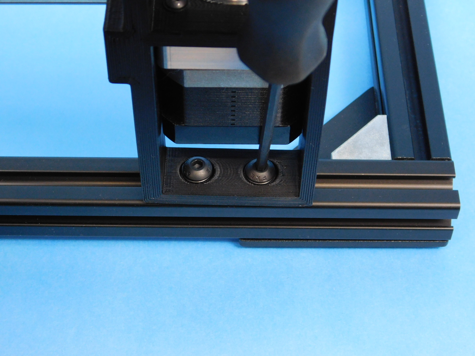
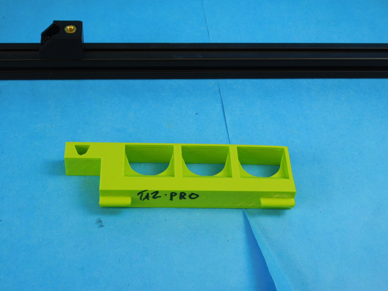
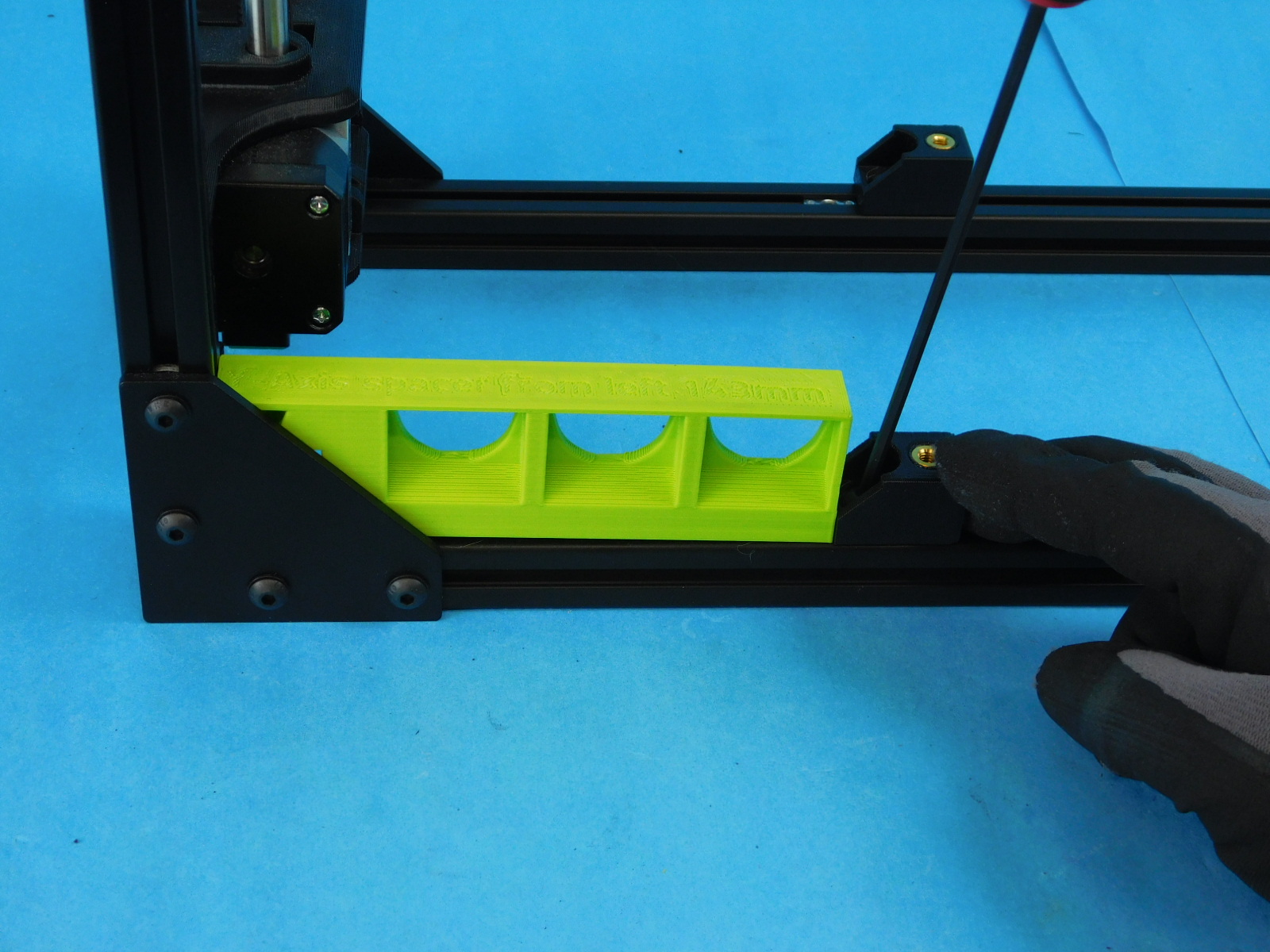
Flip the frame so the corner brackets are facing up. Use three [HD-BT0073] M5 x 10 BHCS and three [HD-WA0040] M5 washer, attach the z-cable chain mount to the frame. Use the spacing jig to set the height.
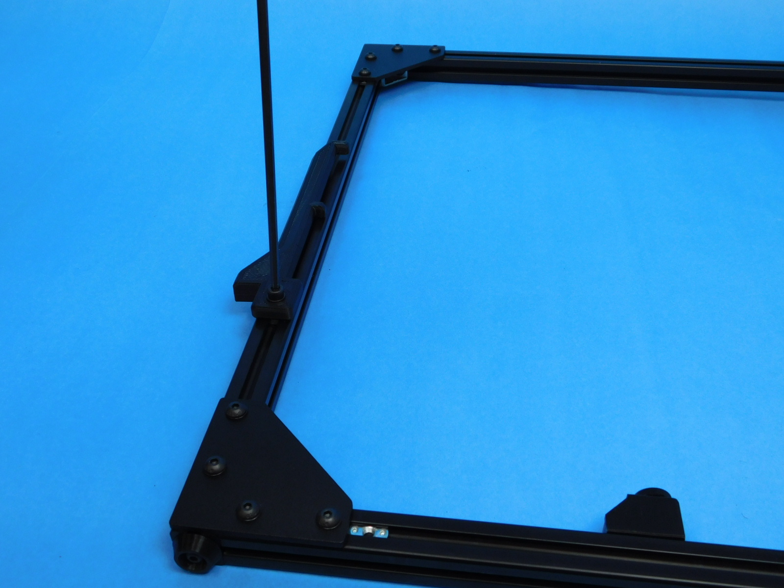
Use one [HD-BT0049] M5 x 14 SHCS and one [HD-WA0040] M5 washer, attach the spool are to rear frame. USe sapcing jig to set the height.
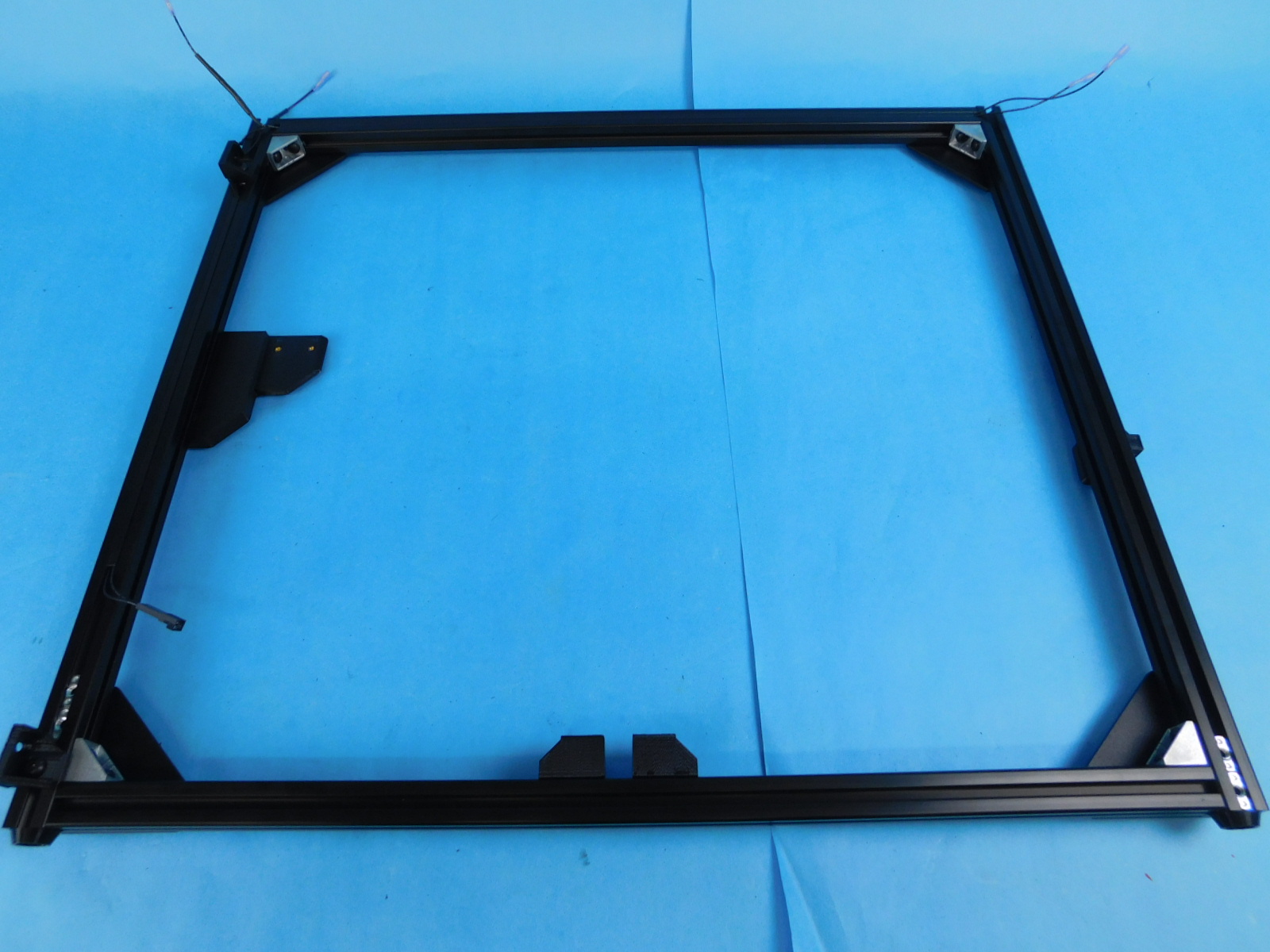
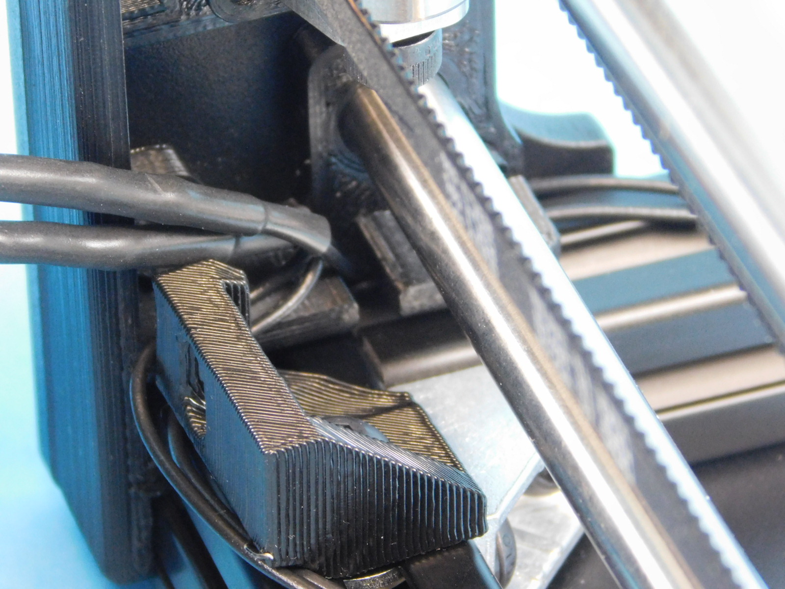
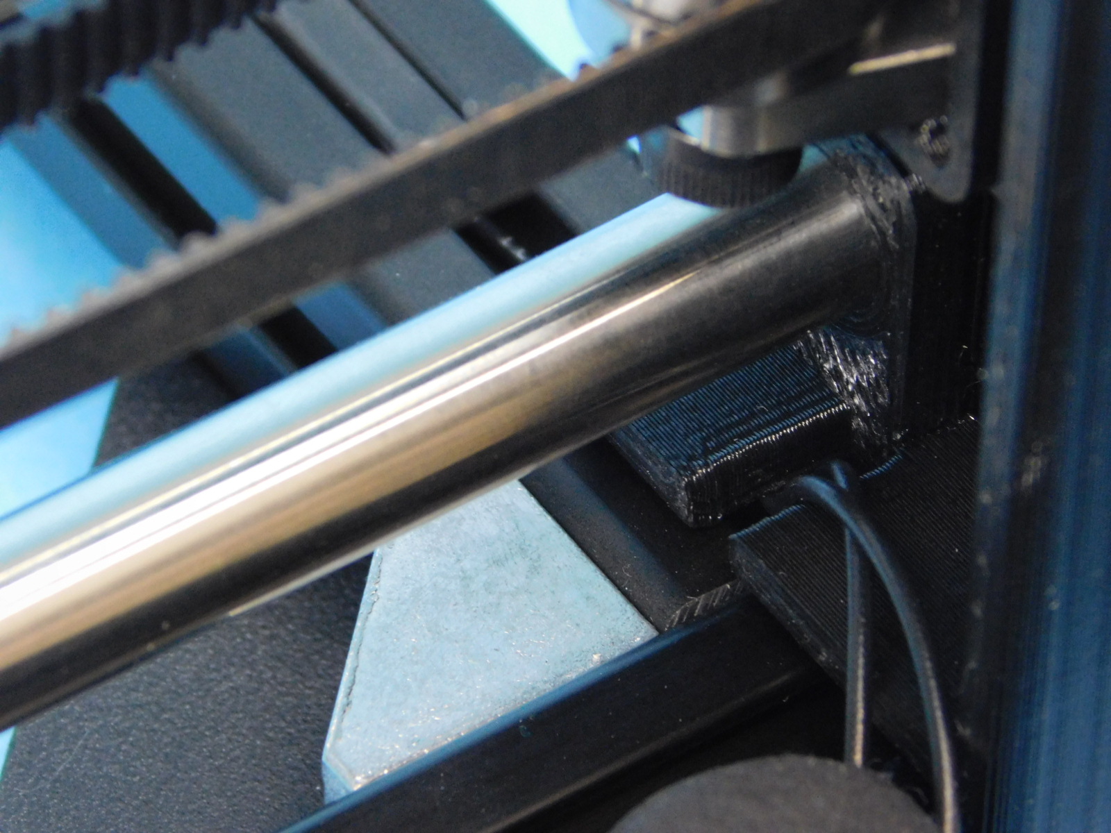
Take the [EL-HR0142] and place it into the frame extrusions as shown. Use the [AS-PR0150] 285mm dust cover and cover the wires on the left side of the frame. Use the [PR0151] 522mm dust cover and cover the wires on the top of the frame.
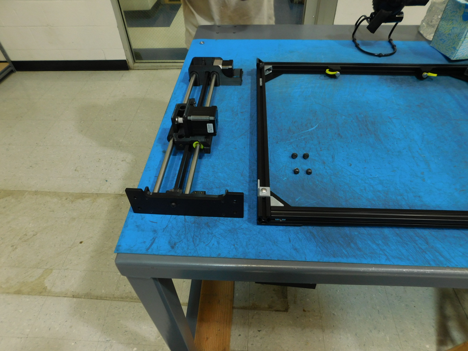
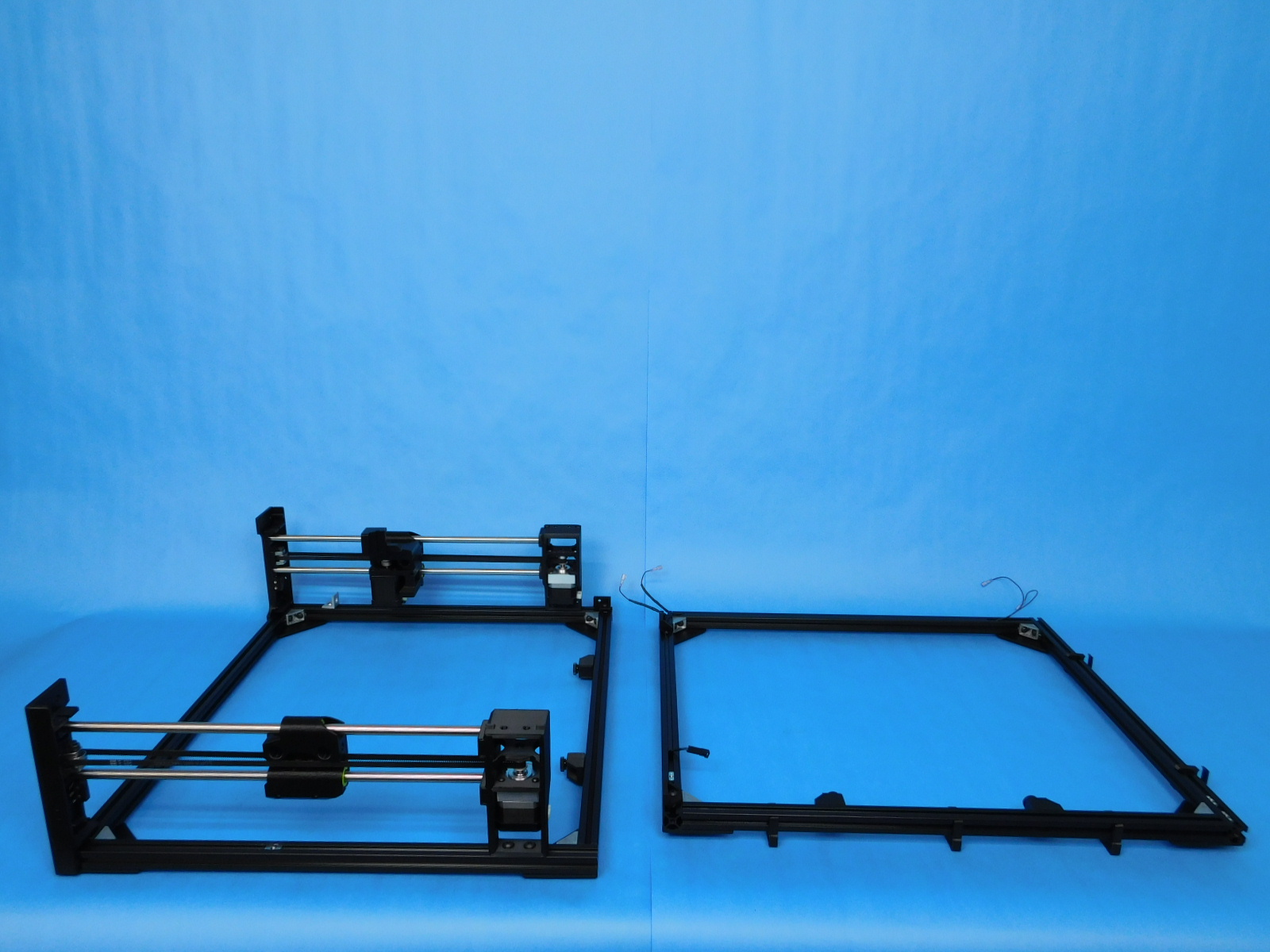
Take the front frame piece and lay it so the bottom of the frame is towards the top.
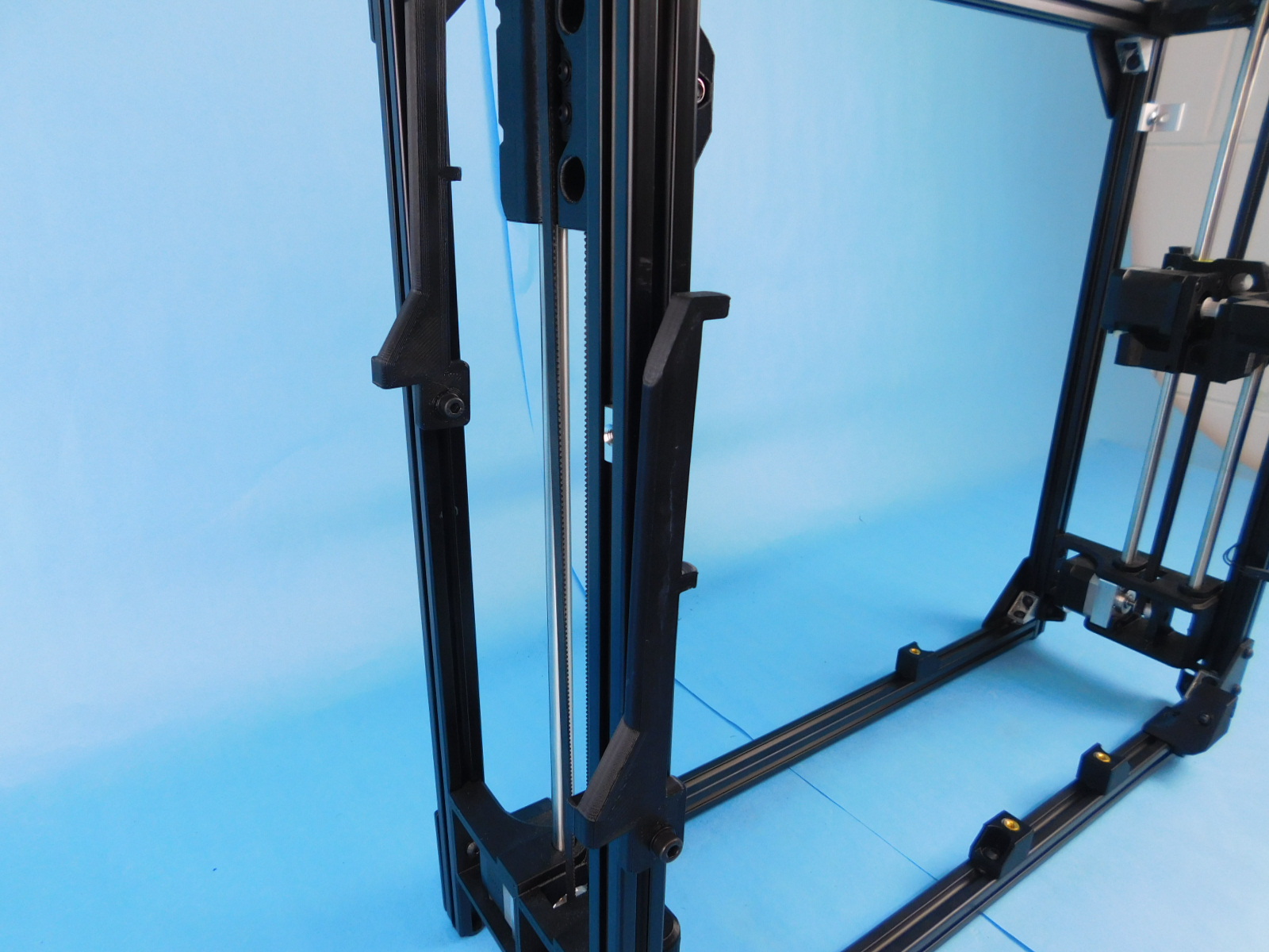
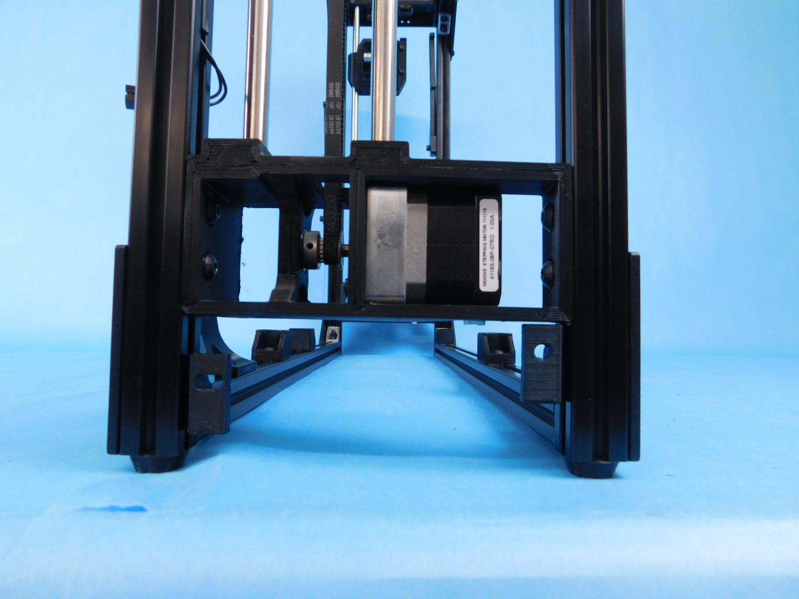
Take the z-motor assembly [AS-PR0136] amd place it on the frame as shown.
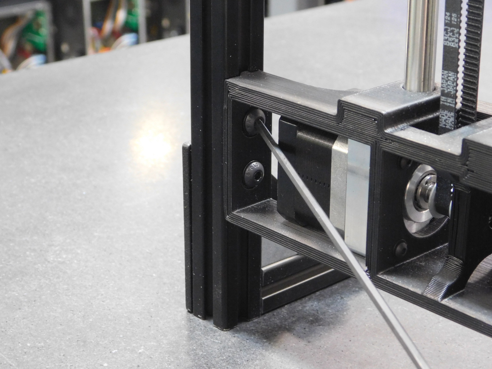
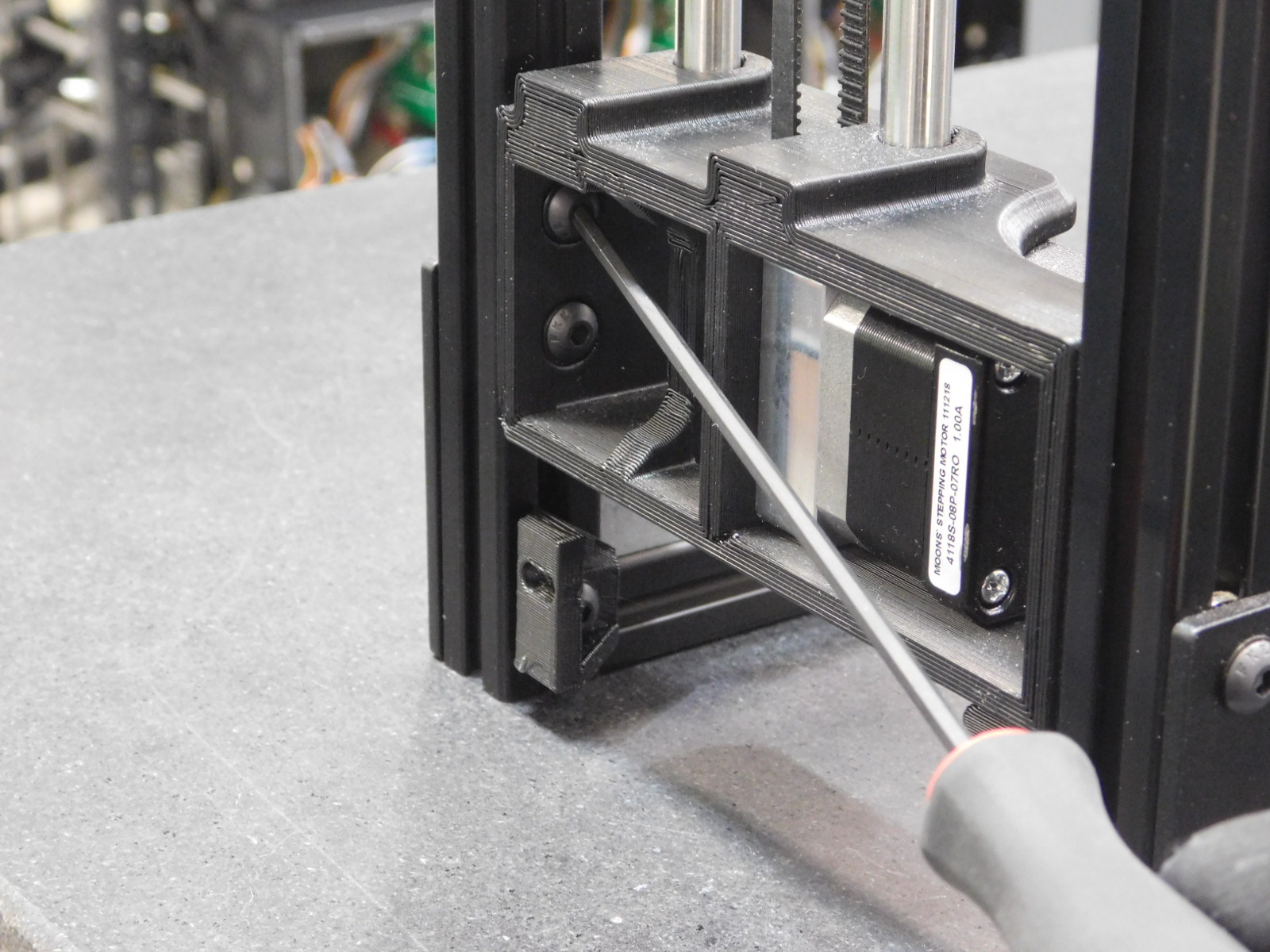
Using two [HD-BT0073] M5 x 10 BHCS and two [HD-WA0040] M5 washer, screw the z-upper to the frame as shown. Use two more [HD-BT0073] and two [HD-WA0040] and attach the z-lower to the frame.
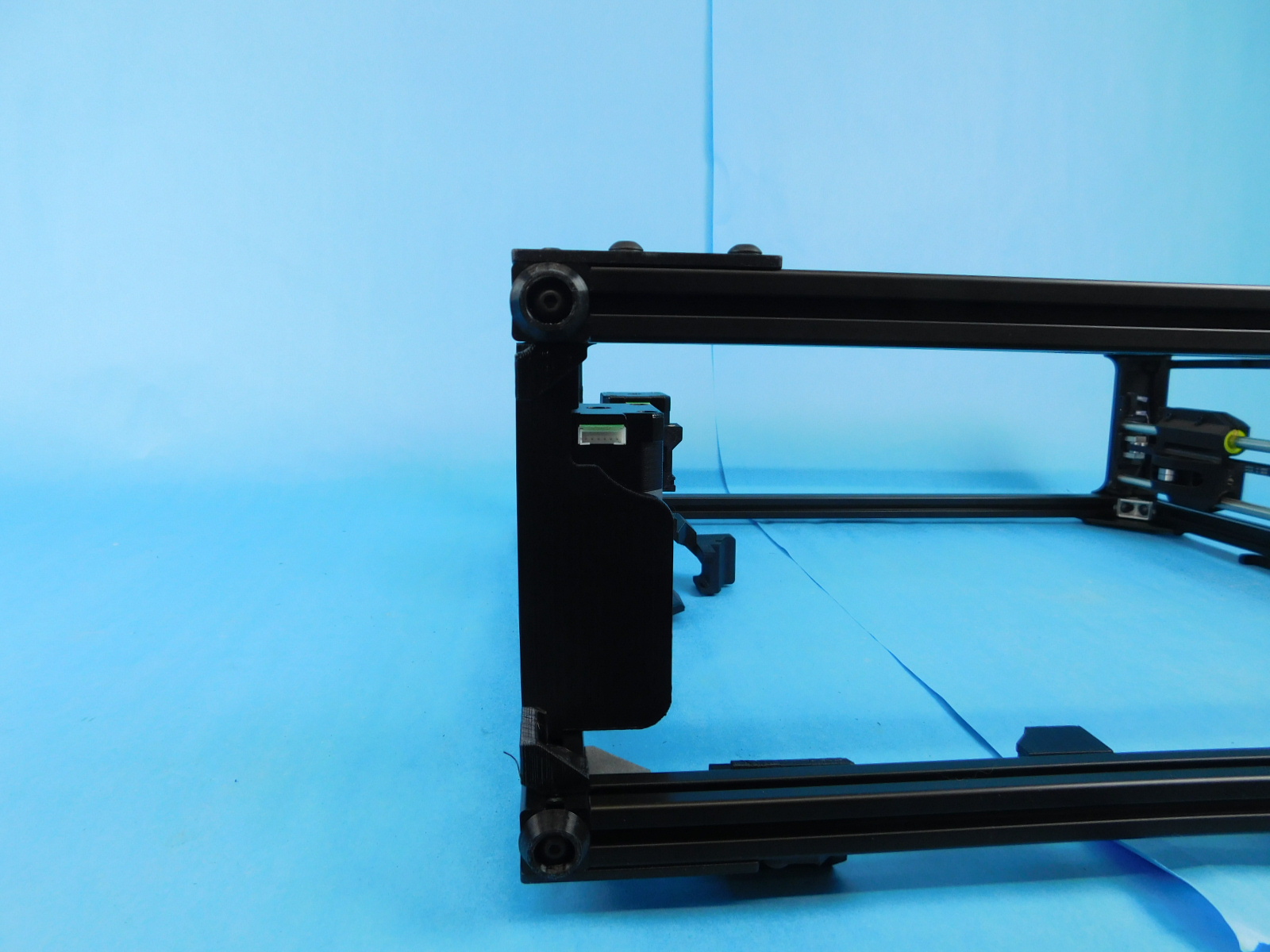
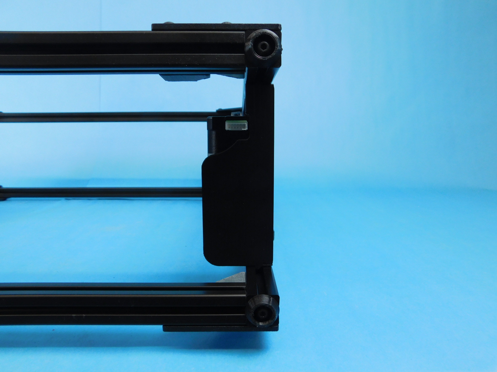
Take the z-idler [AS-PR0130] and place it on the frame as shown.
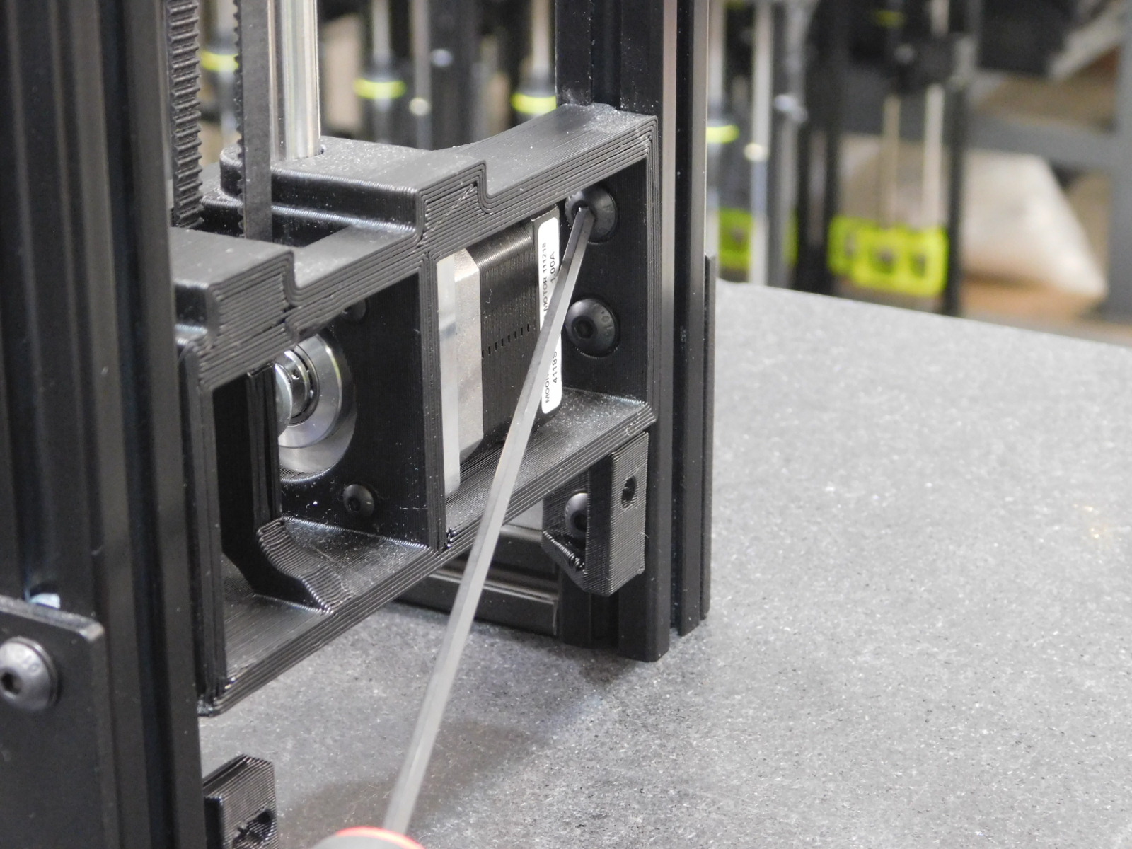
Use two [HD-BT0073] M5 x 10 BHCS and two [HD-WA0040] M5 washer and attach the z-upper to the frame. Use two [HD-BT0073] M5 x 10 BHCS and two [HD-WA0040] M5 washer and attach the z-lower to the frame.
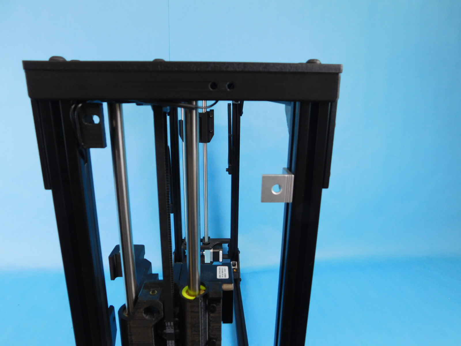
Take the assembled back frame and place it onto the x-ends as shown. Do not pich the wires for the z-max switches when sliding the back frame onto the x-ends.
Use four [HD-BT0073] M5 x 10 BHCS and four [HD-WA0040] M5 washers, and attach the z-uppers to the frame.
Flip the frame over so the screw holes for the z-lowers are facing you.
Use four [HD-BT0073] M5 x 10 BHCS and four [HD-WA0040] M5 washers, to secure the z-lowers to the frame.
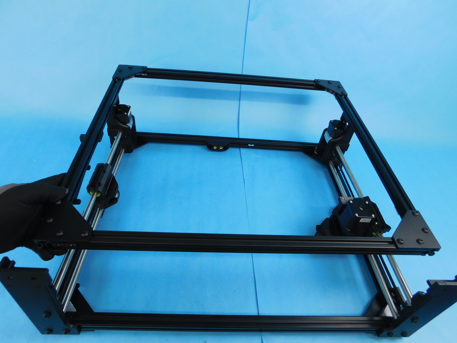
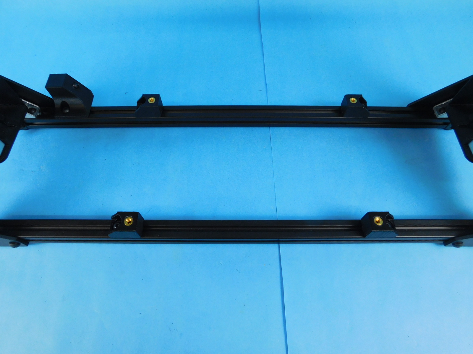
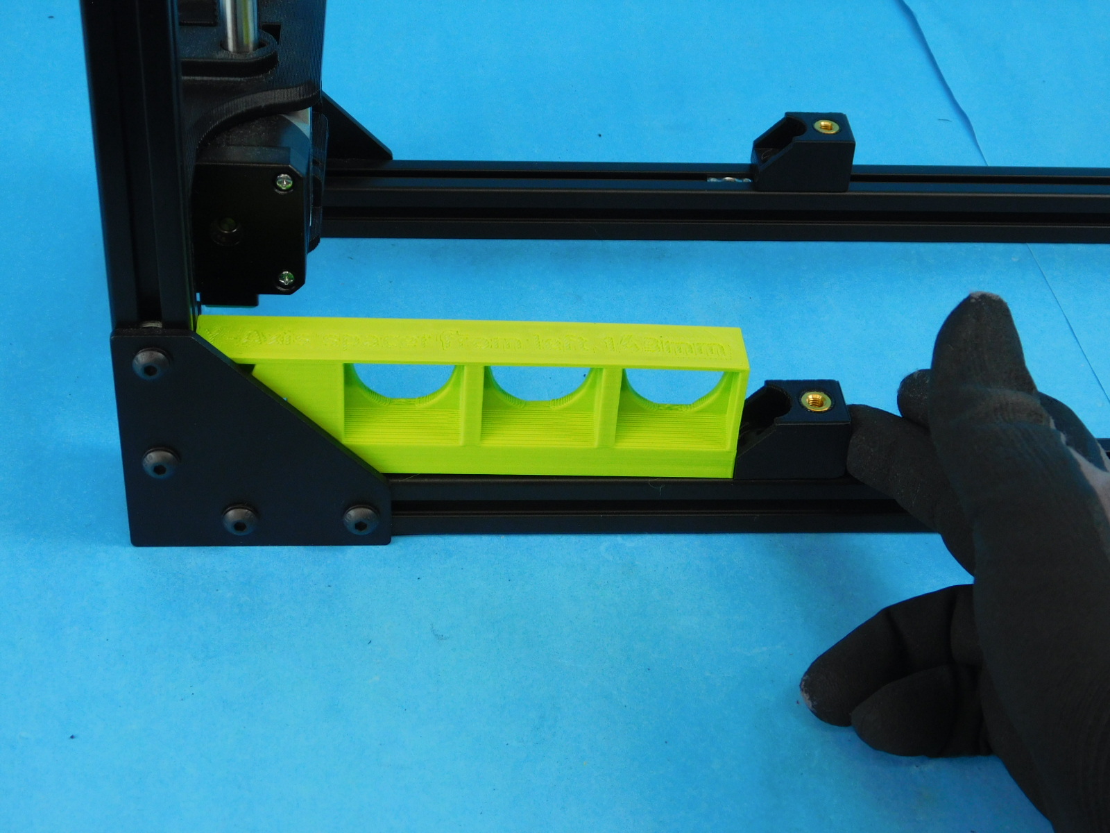
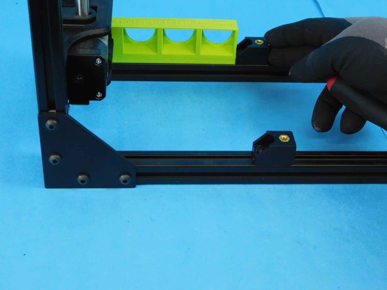
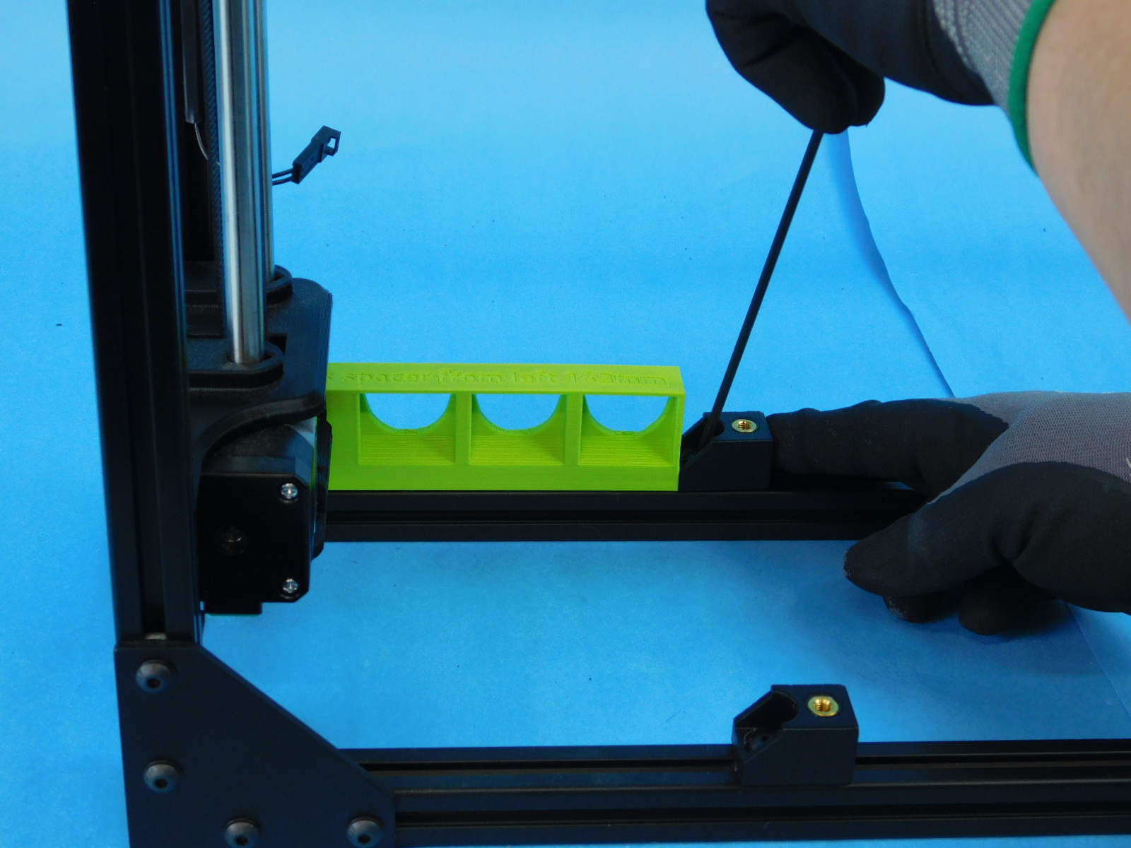
Use the spacing jig for the left two Y-Mount Chassis [PP-IS0098] to get the proper placement.
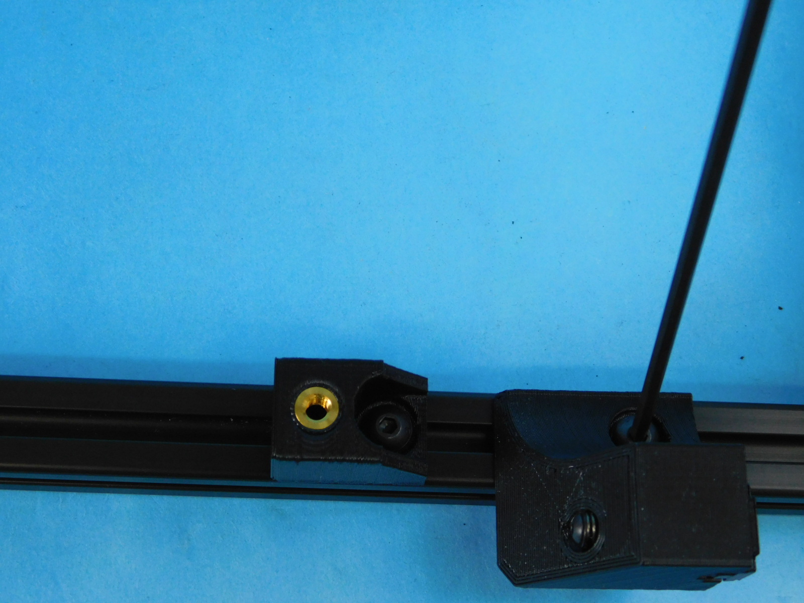
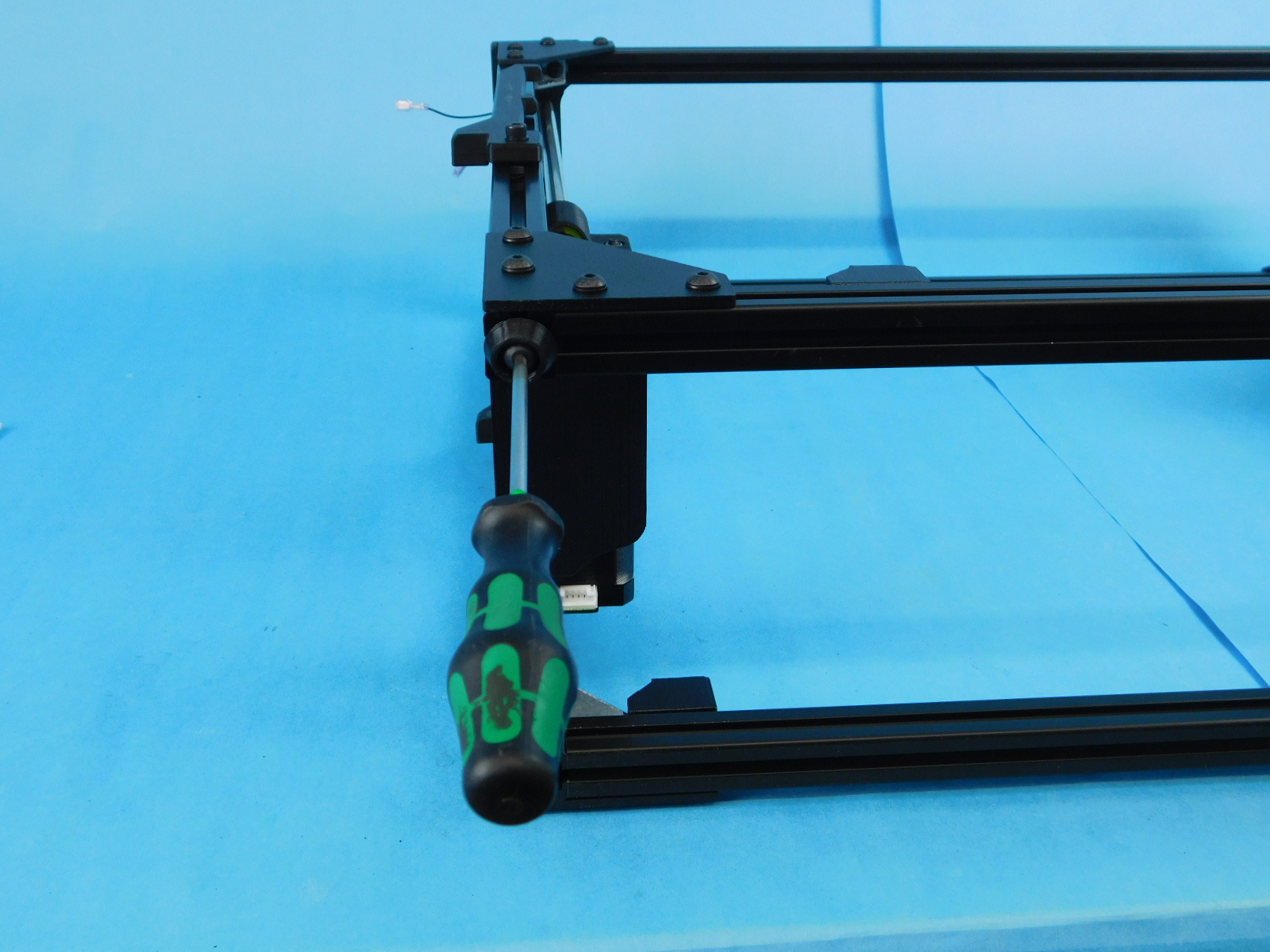
Slide the chassis mount against the jig and tighten it down as shown
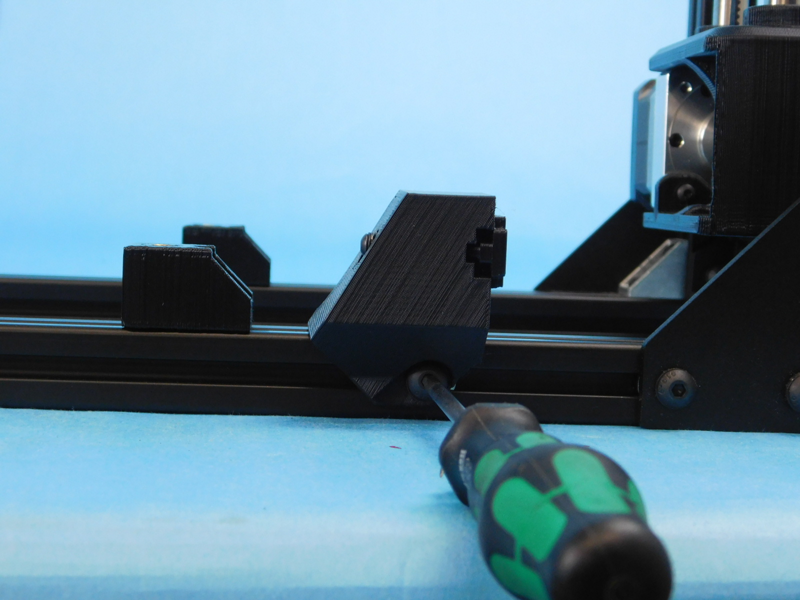
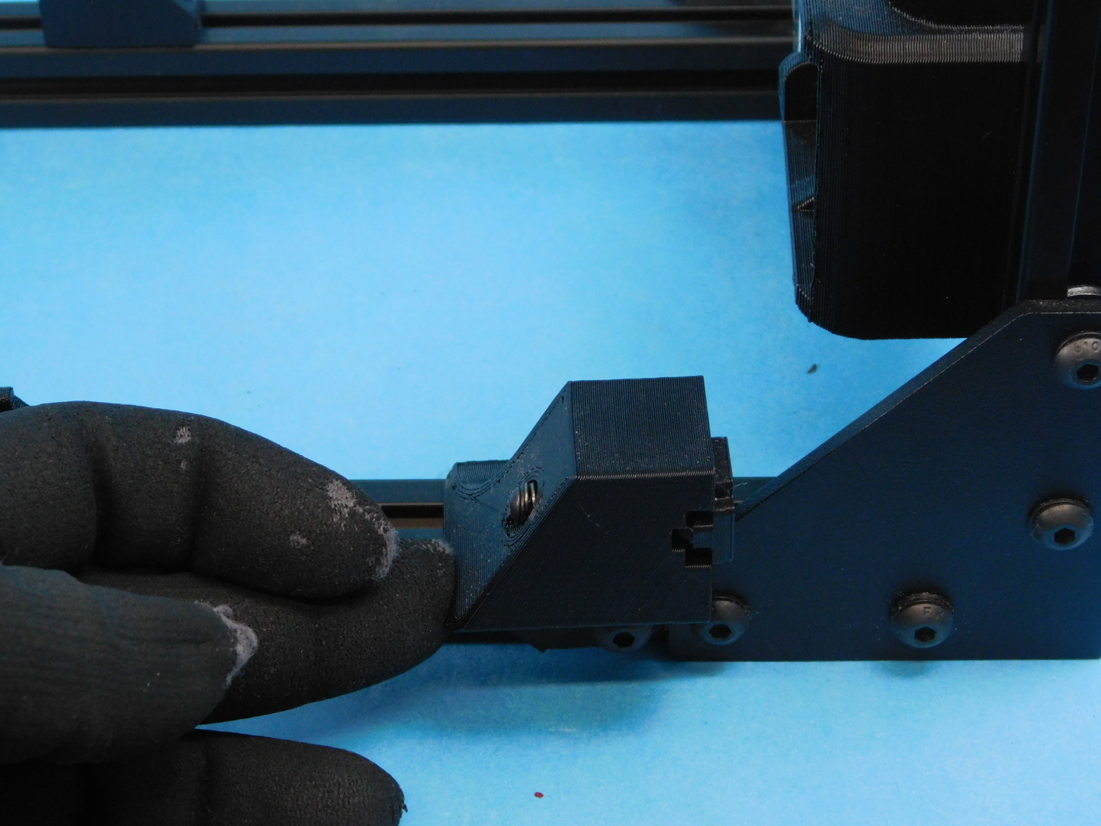
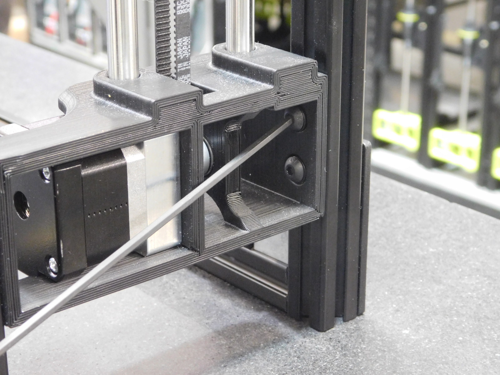
Take the y-chain pivot assembly [AS-PR0138] with two [HD-BT0073] and two [HD-WA0040] and attach the pivot mount.
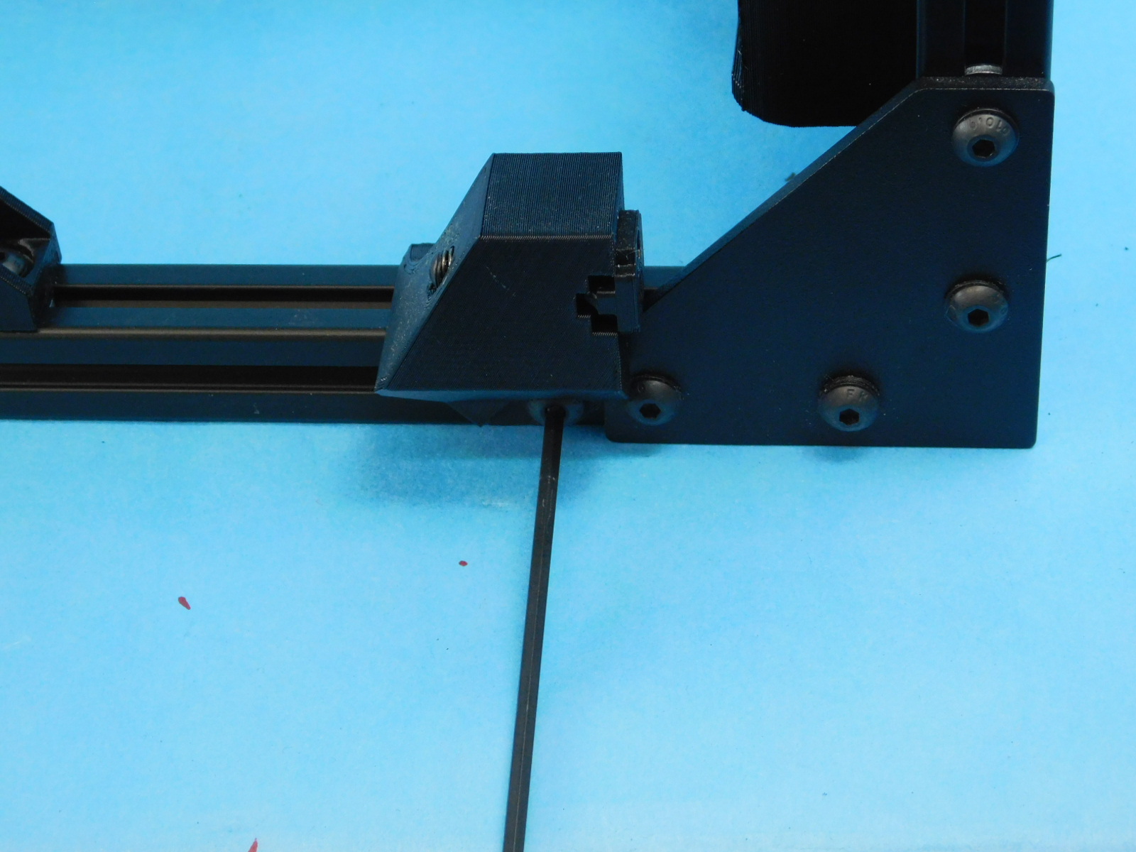
Start the screws loosely then slide the pivot mount all the way against the corner bracket as shown. Finish tightening the screws down.
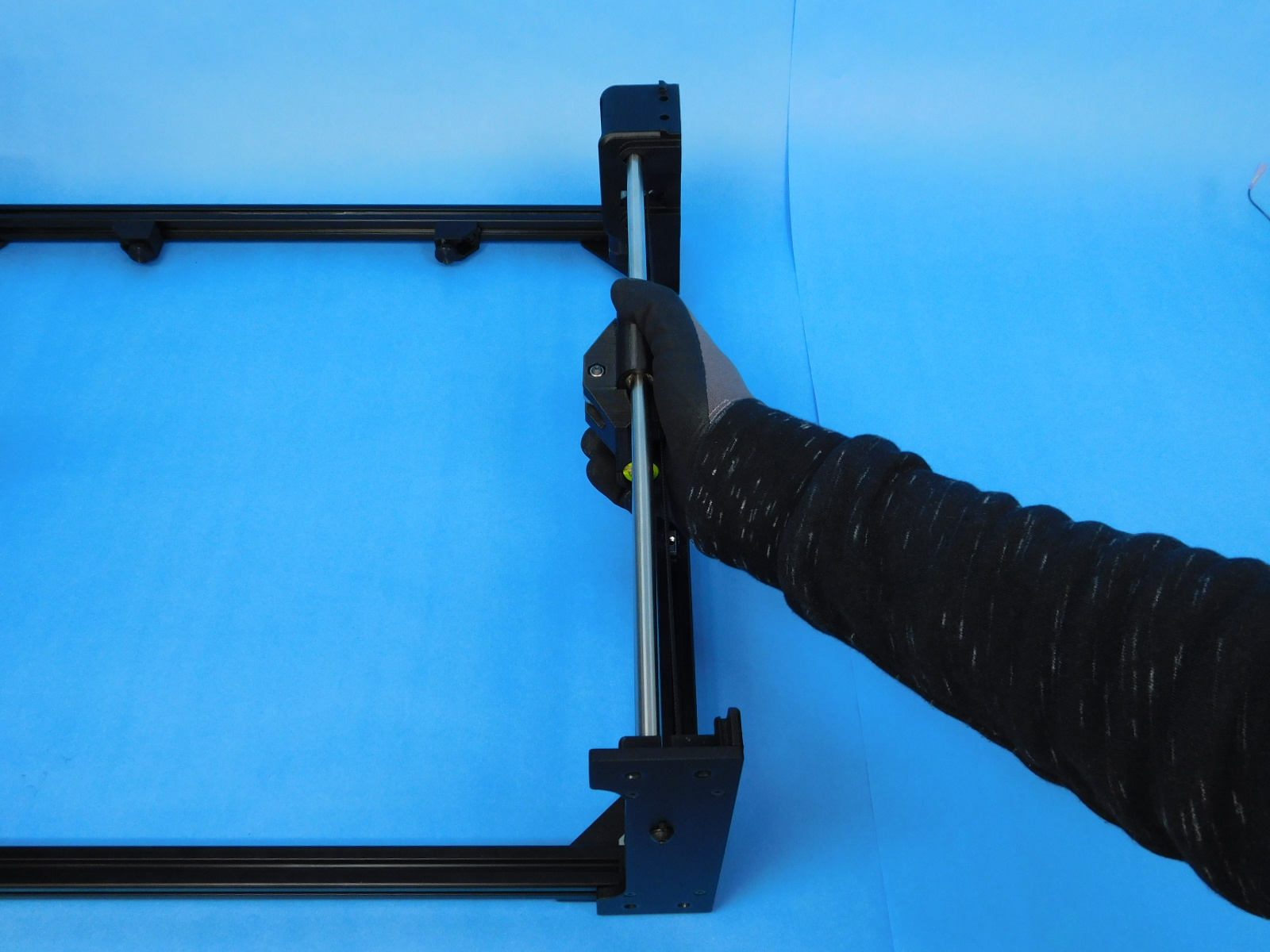
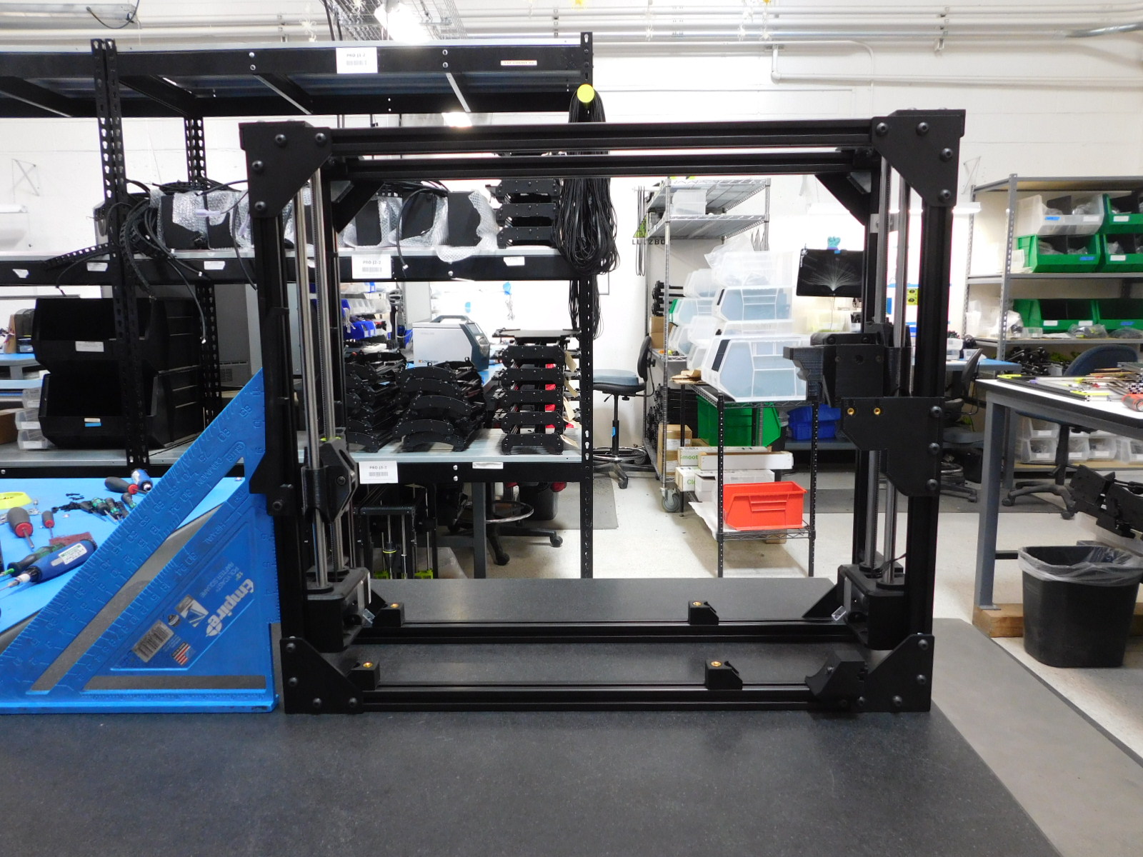
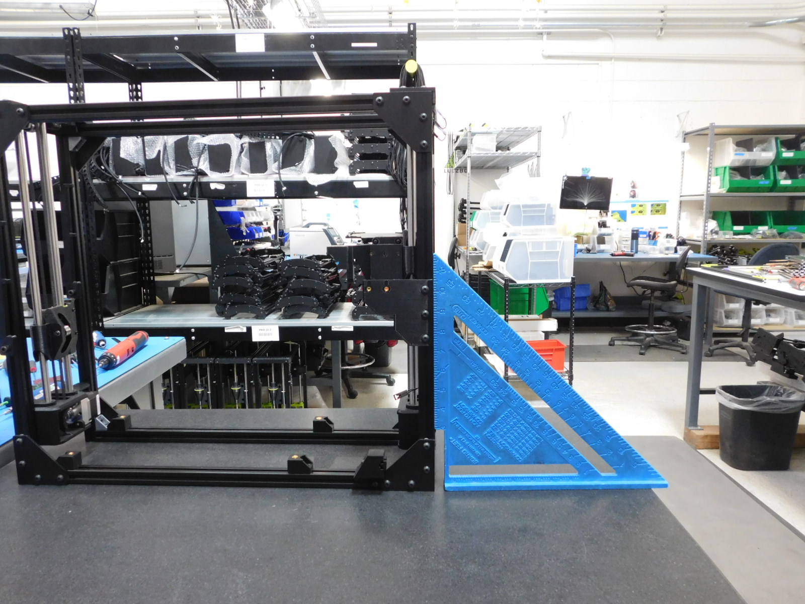
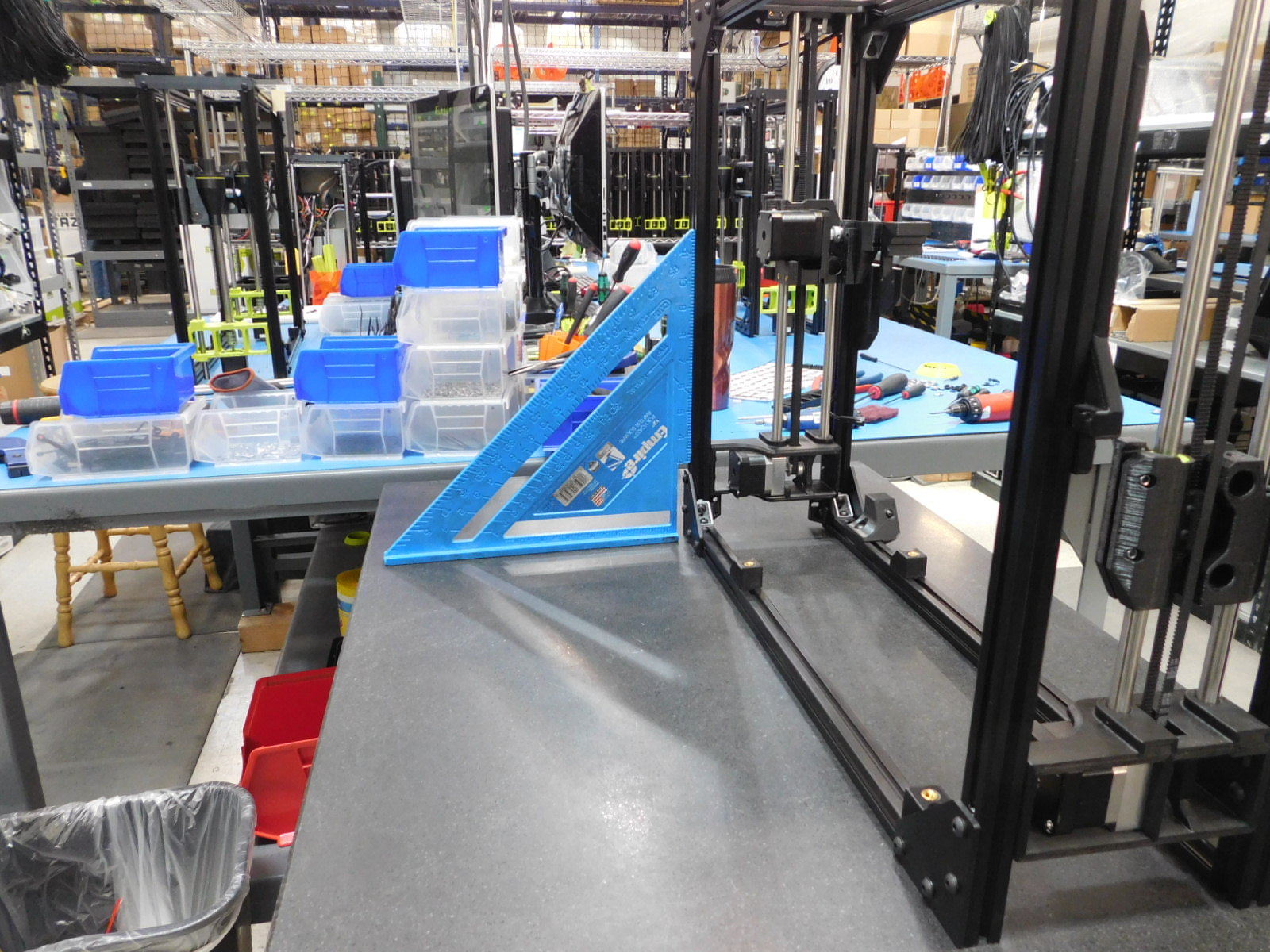
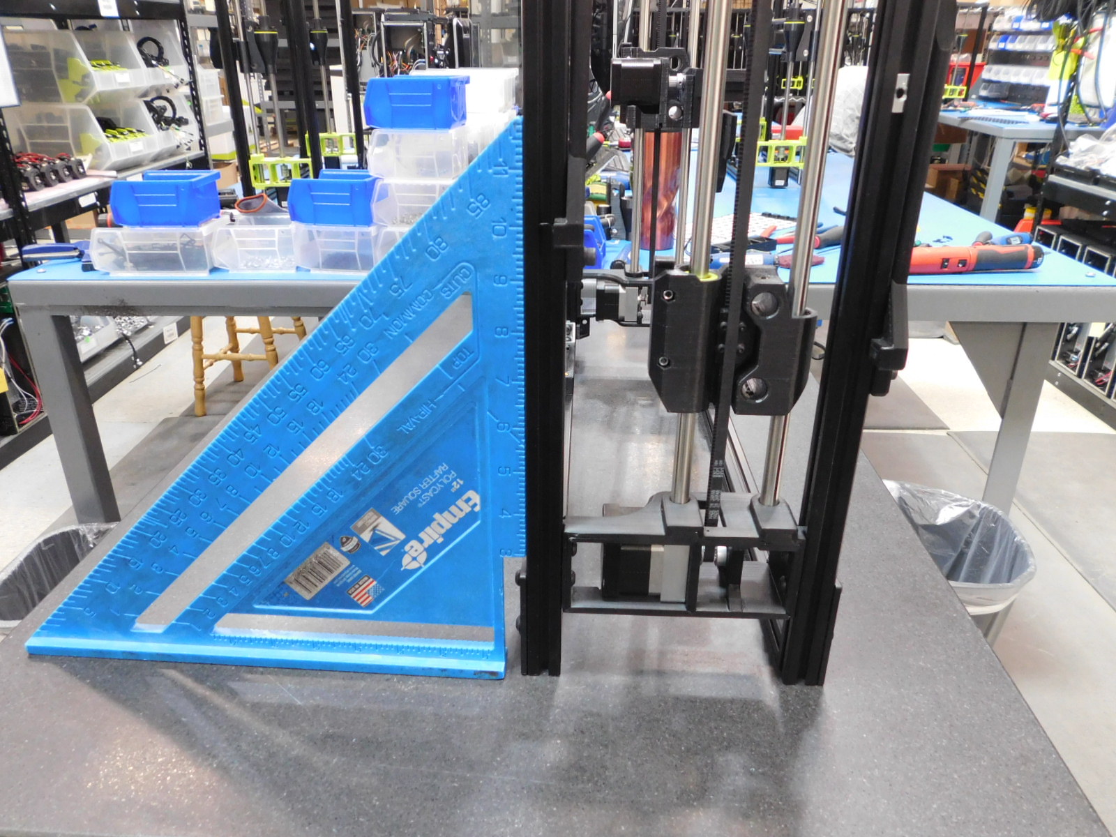
Take the frame to the granite block and check the squareness of the frame. Use a 12" rafter square to check the frame for squareness. The frame must be within 2mm of the rafter scale on either the top or bottom of the square.
Attach the four frame feet [PP-GP0409] to the frame using four [HD-BT0073] M5 x 10 BHCS with four [HD-WA0040] M5 washer.
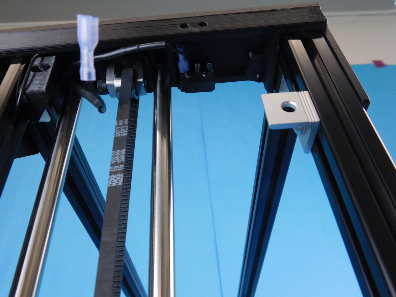
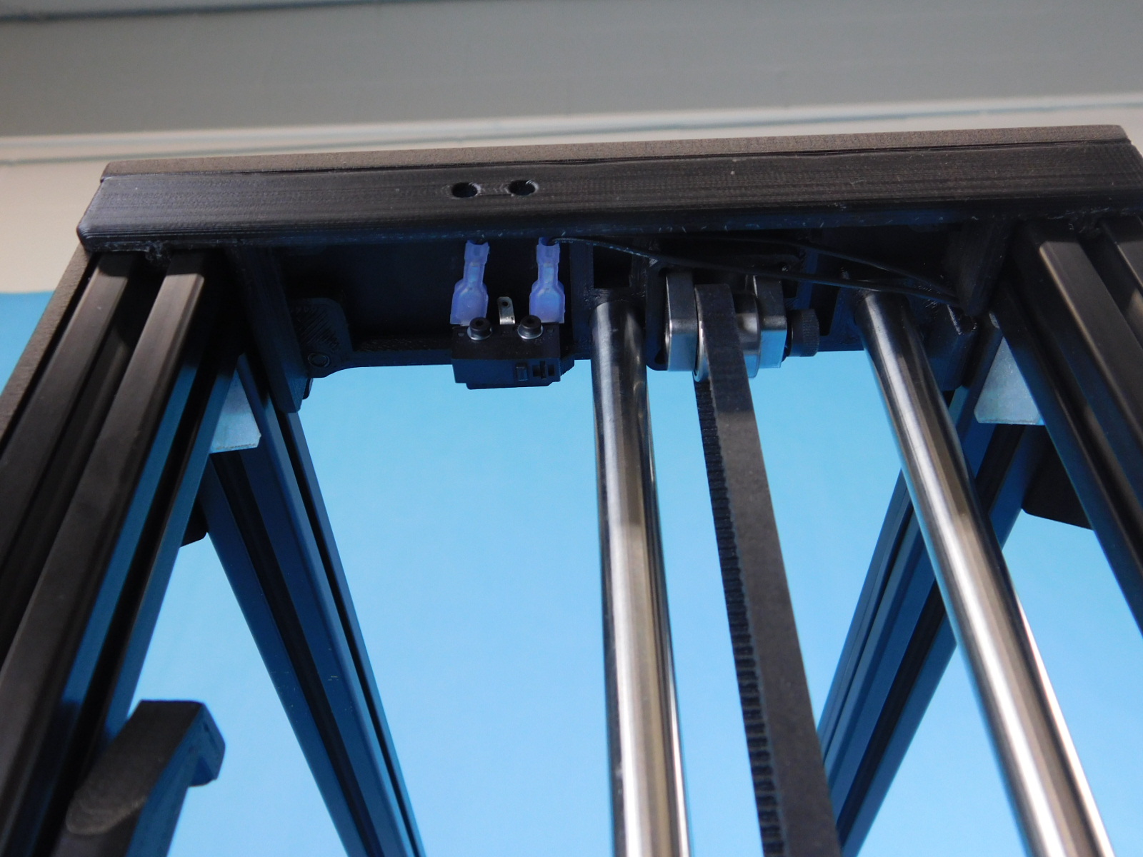
Plug in the wires for the z-max switches as shown.
There are no loose or un-torqued screws.
Both spool arms are attached.
Z-cable chain mount is attached.
All four y-chassis mounts are attached and in the correct place with the spacing jig.
Y-chain pivot assembly is attached and up against the frame corner.
Z-max wires are plugged in and going to correct terminals.
All four feet are attached.