Open HardwareAssembly Instructions
Guides for installation and assembly of the LulzBot line of products made by Aleph Objects, Inc.
Guides for installation and assembly of the LulzBot line of products made by Aleph Objects, Inc.
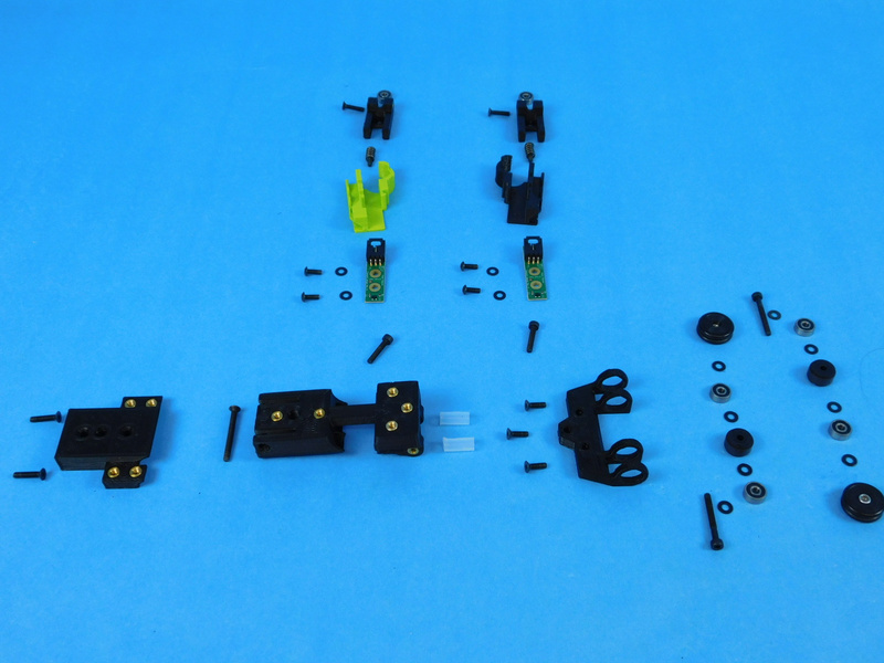
Assemble the materials needed for the [AS-PR0144] Filament Sensor Assembly
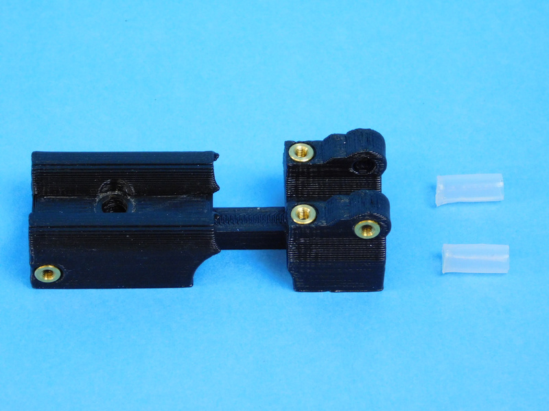
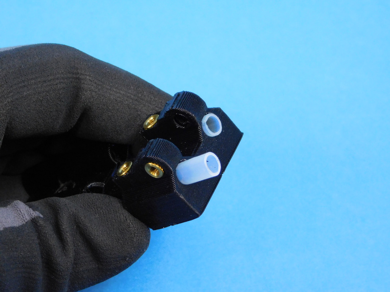
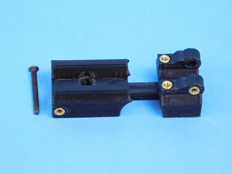
Cut out 2x 9.5mm [HD-TB0007] Feed tubes and slide them into the Dual tube clamp with inserts [PP-IS0108].
Fasten the clamp end of the dual tube clamp using an M3X30mm FHCS [HD-BT0224].
Do not tighten, this will serve to hold the filament tubes firmly in place.
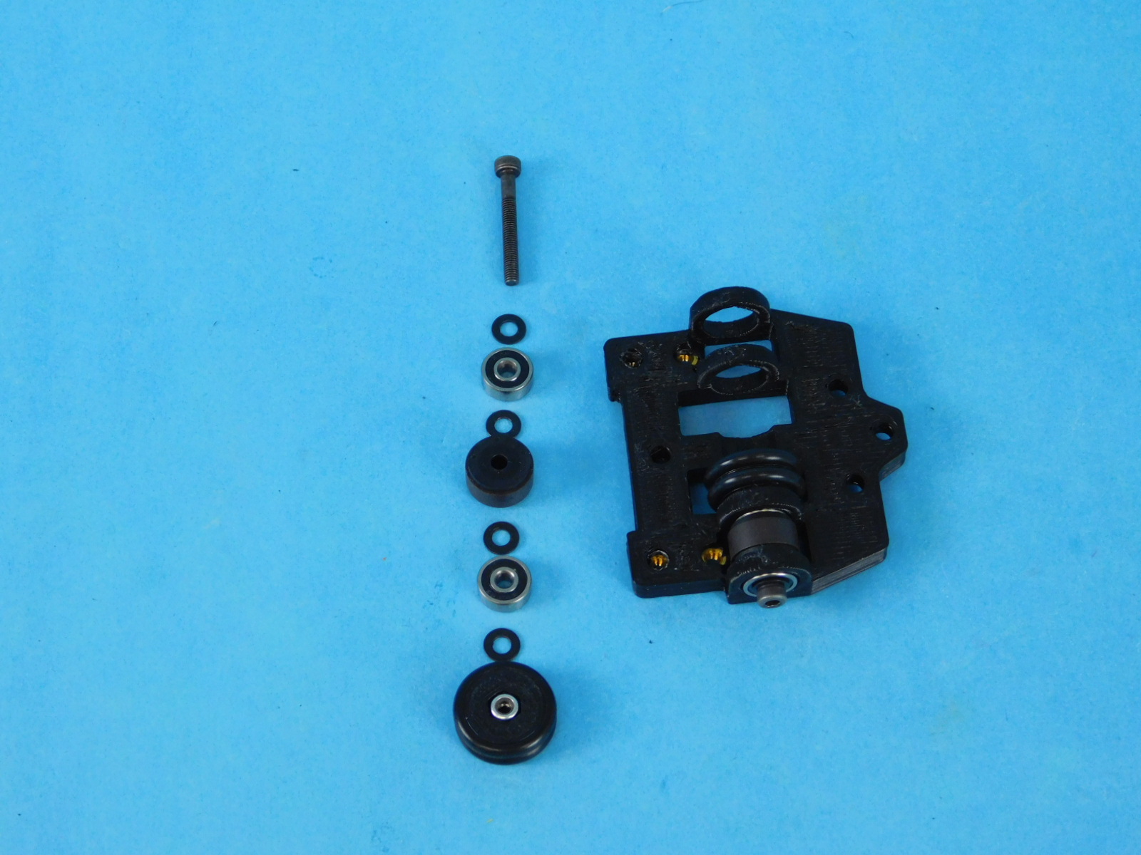
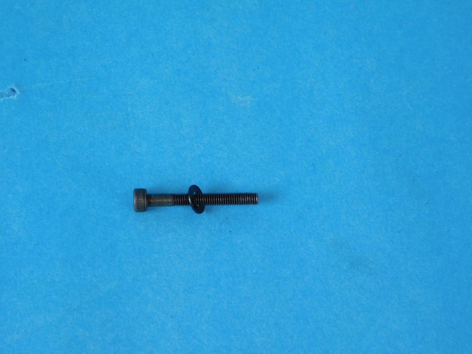
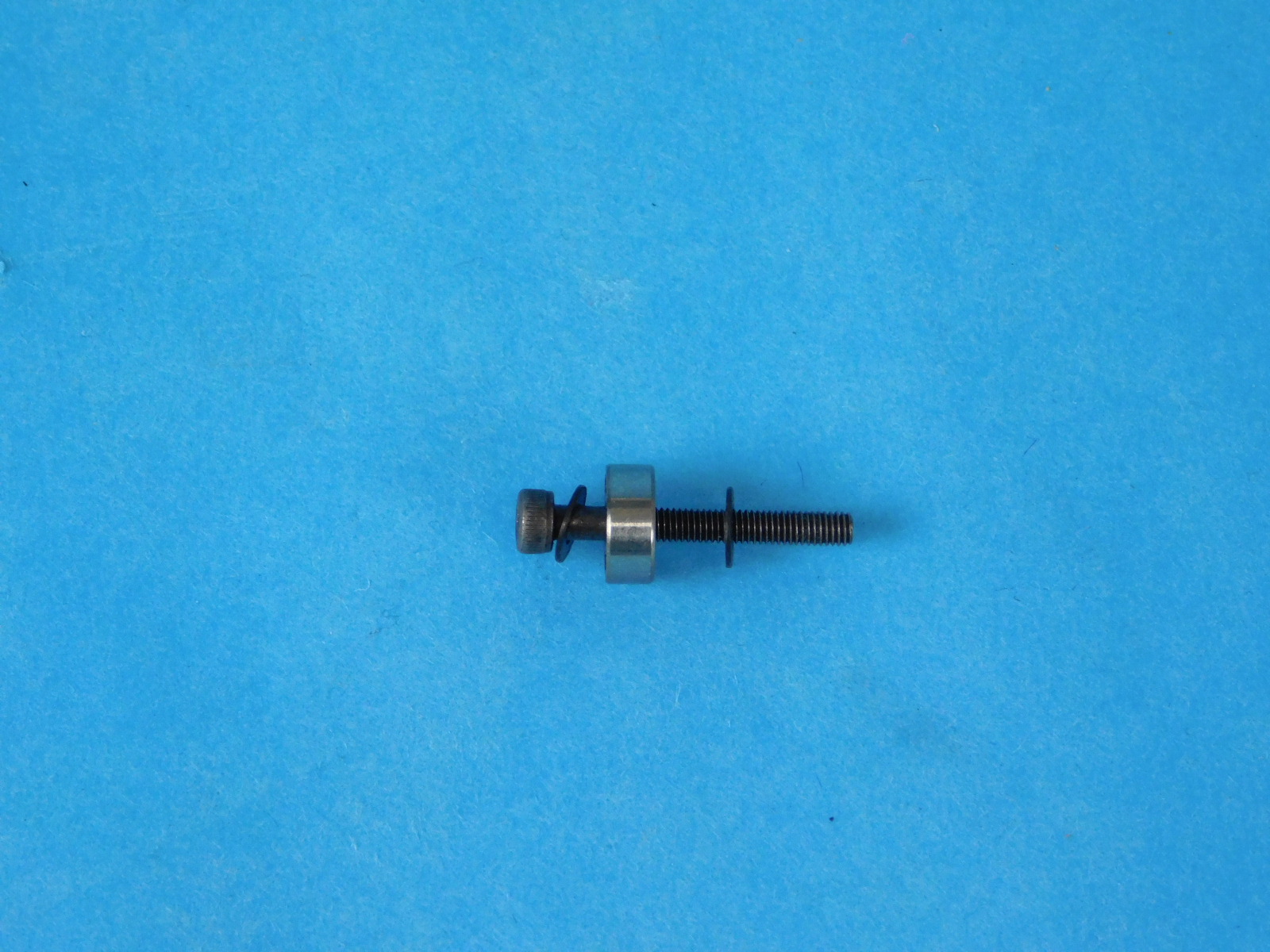
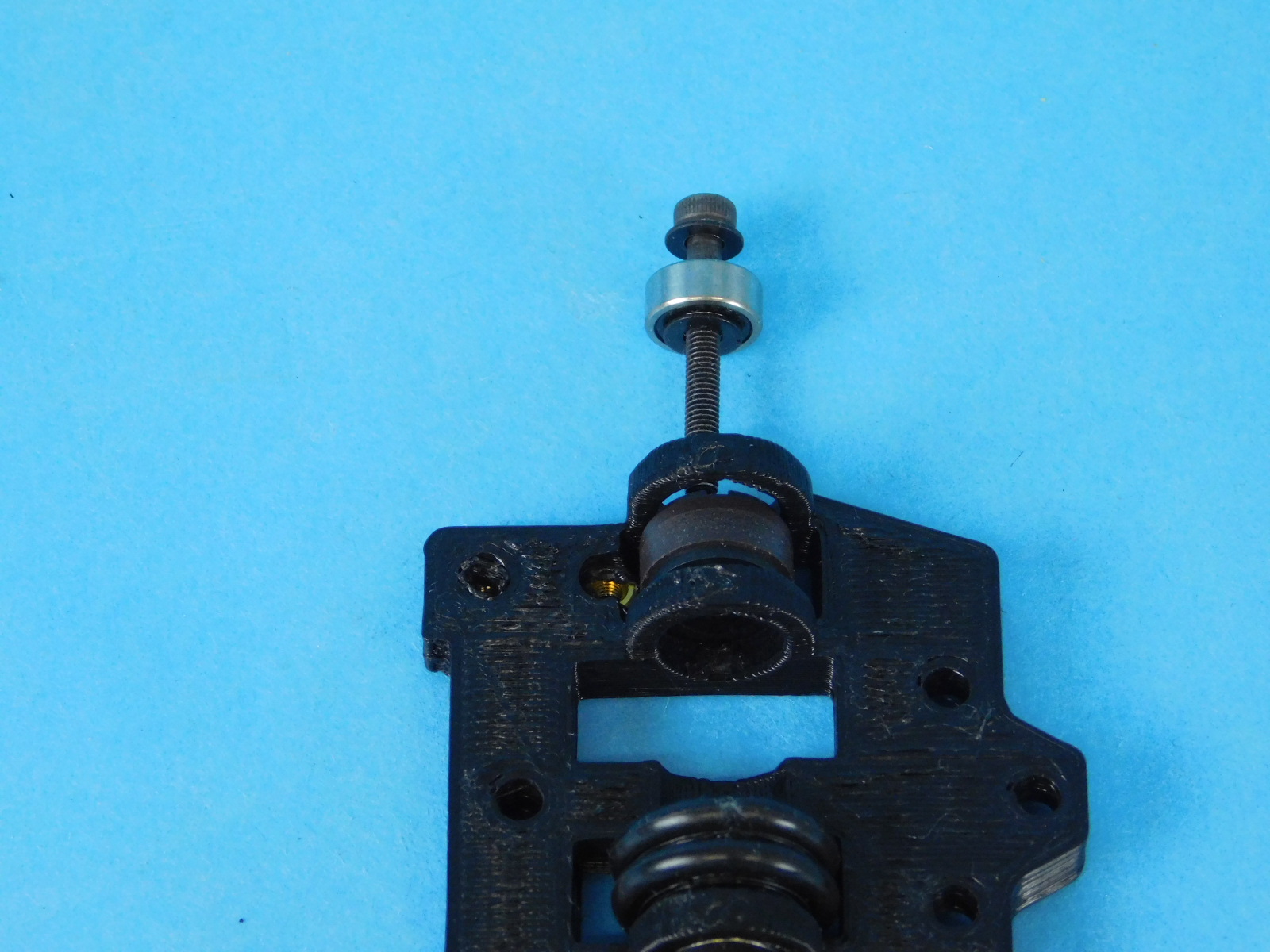
Start by taking an M3X25mm SHCS [HD-BT0041] fastener, sliding on an M3 washer [HD-WA0038], and rubber sealed bearing [HD-MS0470], and followed up by another washer [HD-WA0038]. Insert the rubber sealed bearing through the first ring on the Bearing Mount [PP-GP0414].
Slide another M3 washer [HD-WA0038] along the screw and push the fastener through a Multipole ring [EL-MS0531]. Follow it up with another washer [HD-WA0038] and then slide the rubber sealed bearing [HD-MS0470] into the second ring of the mount.
Follow this up with another washer [HD-WA0038].
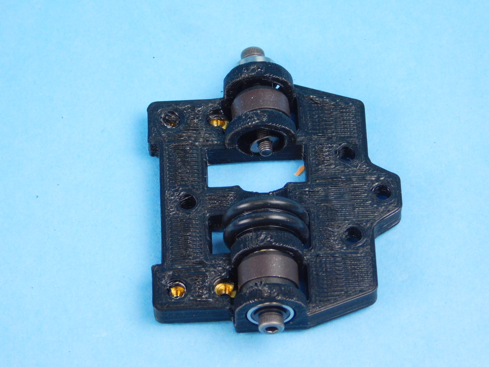
Take the Filament Wheel [PP-GP0418] and install 2x O-rings [HD-MS0467] into the grooves and an M3 Nyloc Nut [HD-NT0001] into the provided slot on the plastic part with the nylon side facing out.
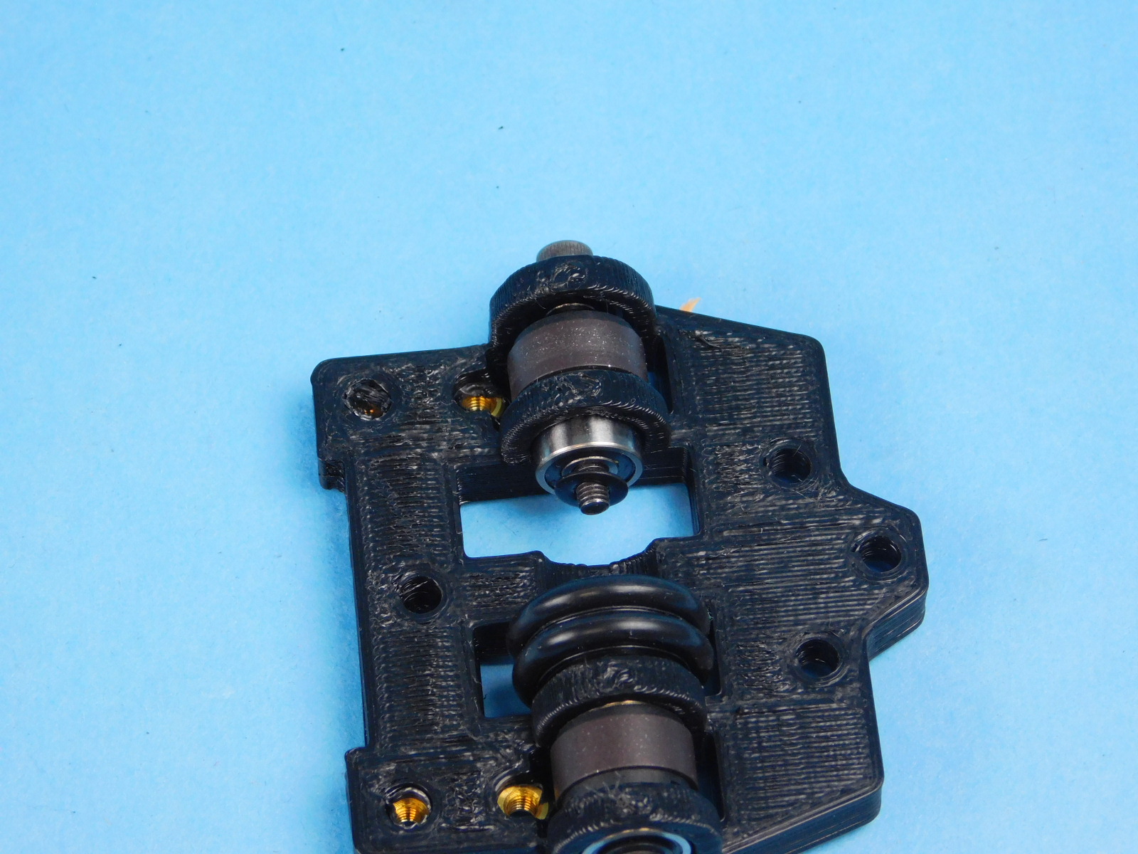
Slide it on to the stack and fasten the screw until it sits tight with no side to side movement.
Repeat these steps for the other side.
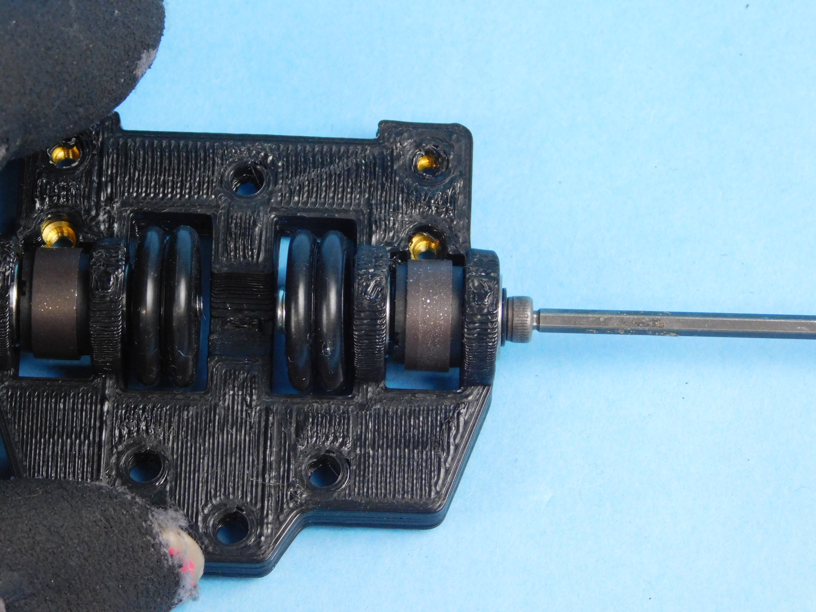
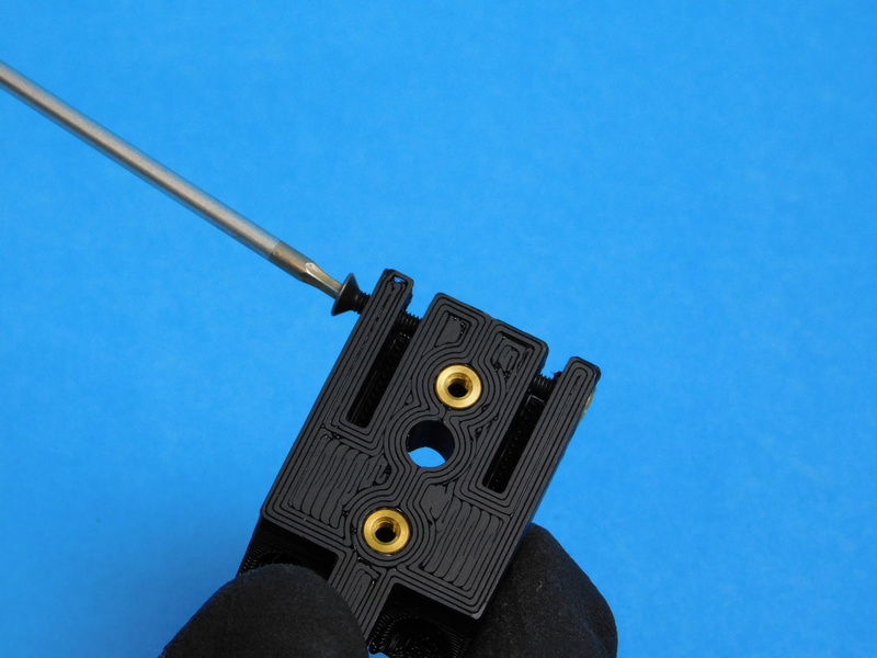
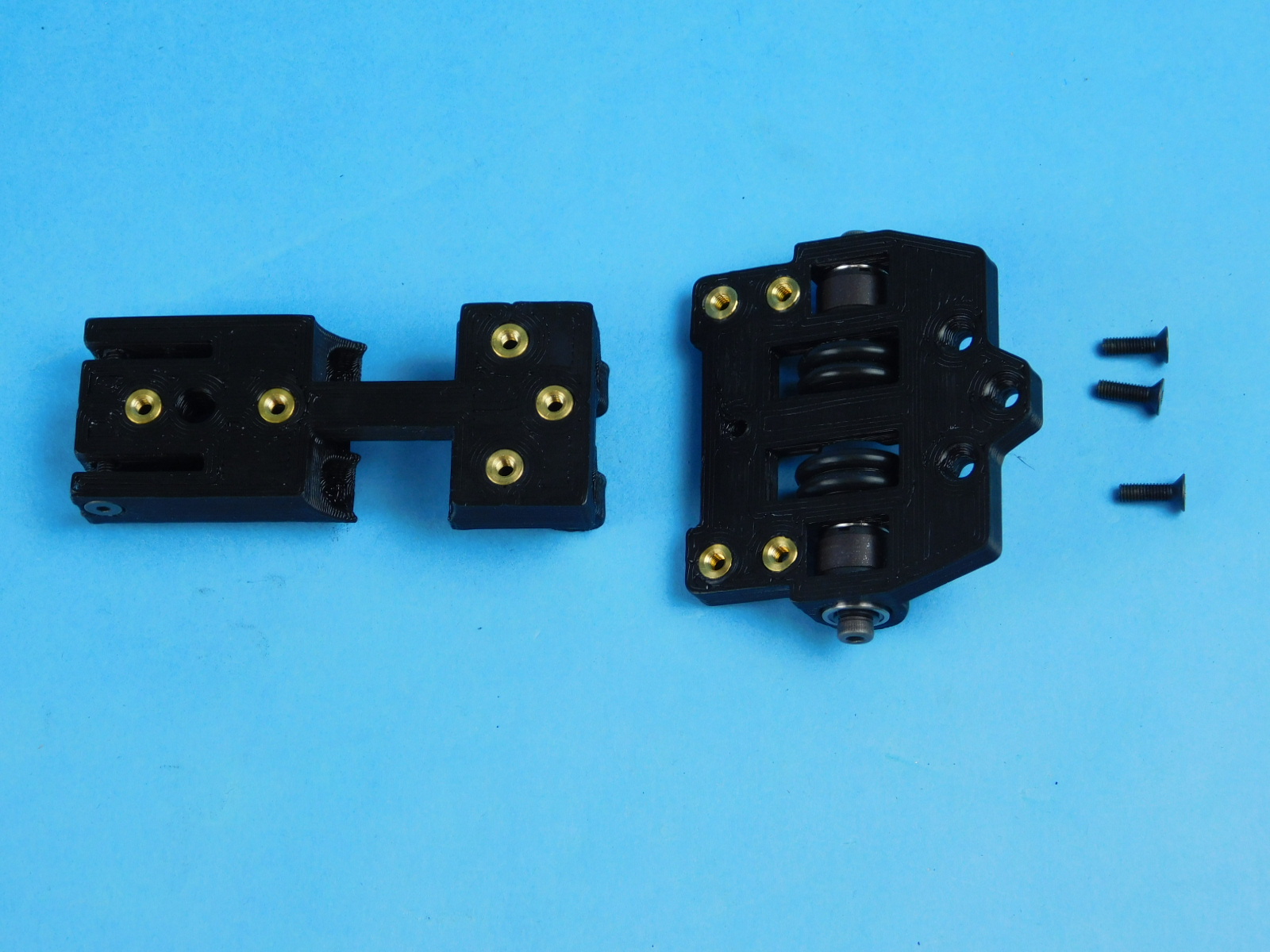
Fasten the encoder wheel on to the Dual Tube Clamp using 3x M3X10mm FHCS [HD-BT0116].
Torque to 5in*lbs
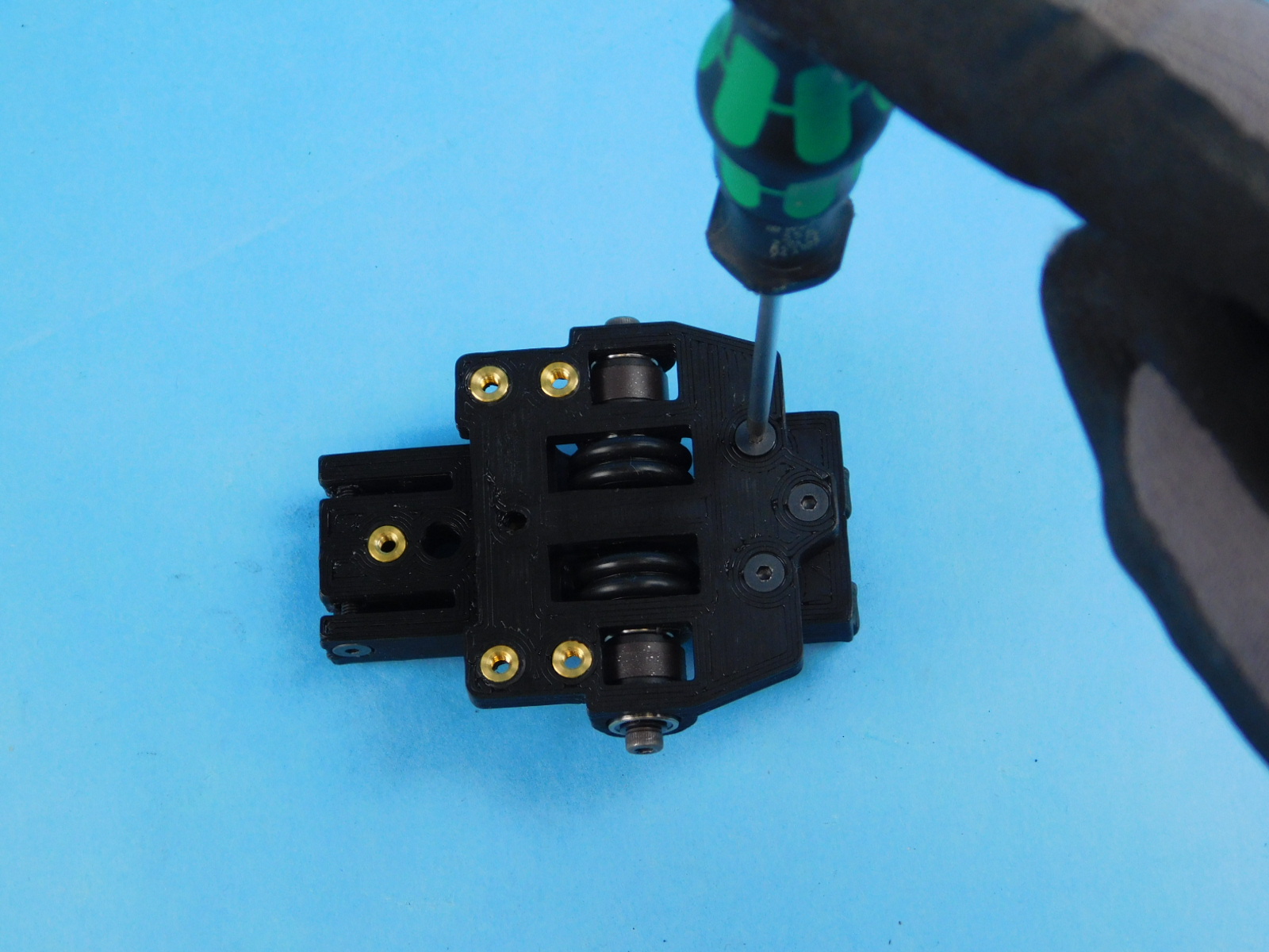
Fasten the Filament Sensor Mount w/ Inserts [PP-IS0114] to the Dual Tube Clamp using 2x- M3X14 FHCS [HD-BT0118], making sure that the slant of the mount is fitting over the encoder wheel.
Torque to 5in*lbs
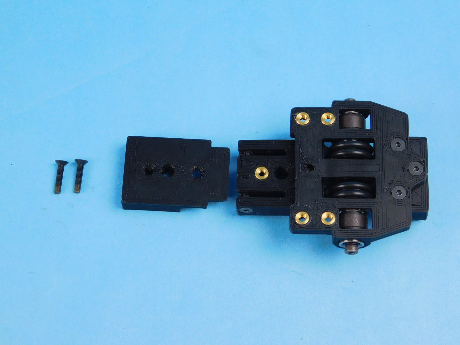
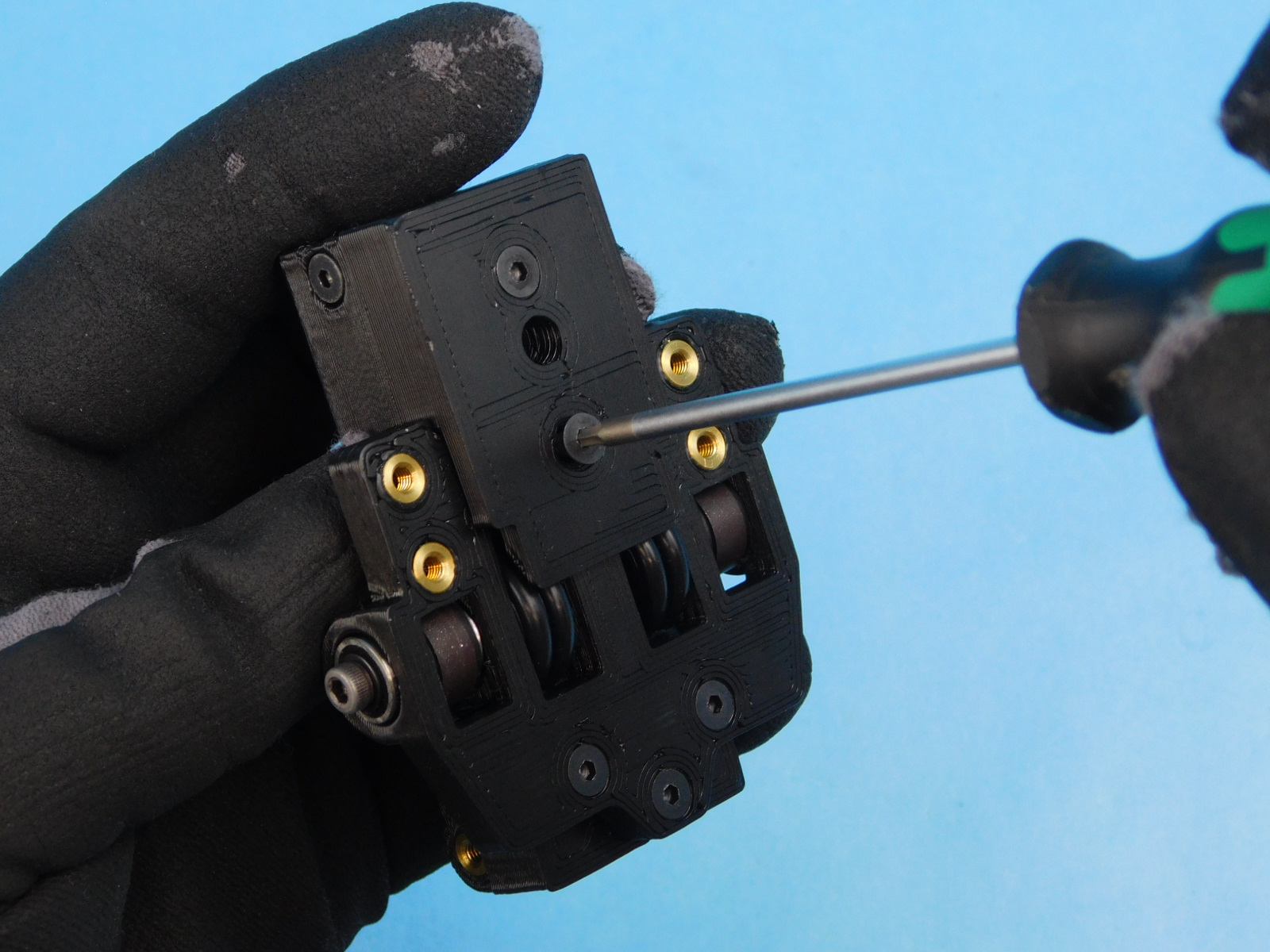
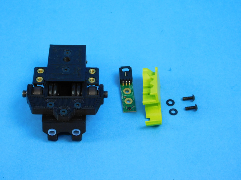
Place the Filament Sensor Board [PC-BD0109] to the left side of the filament sensor mount with the connector facing towards the front of the assembly.
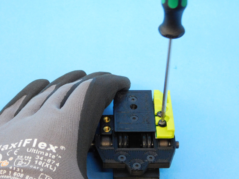
Slide the Sensor Cover L [PP-GP0417] over top of the sensor board before fastening it down with 2x- M3X8 BHCS [HD-BT0137] with washers [HD-WA0038].
Push the filament sensor board towards the bottom of the assembly before tightening
Torque to 3in*lbs
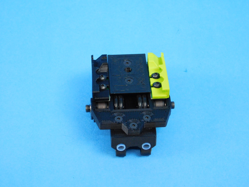
Repeat this for the right side using Sensor Cover R [PP-GP0416];
Place the Filament Sensor Board [PC-BD0109] to the right side of the filament sensor mount with the connector facing towards the front of the assembly.
Slide the Sensor Cover R [PP-GP0416] over top of the sensor board before fastening it down with 2x- M3X8 BHCS [HD-BT0137] with washers [HD-WA0038].
Push the filament sensor board towards the bottom of the assembly before tightening
Torque to 3in*lbs
Turn the encoder through several rotations to make sure that it does not rub on the filament sensor board.
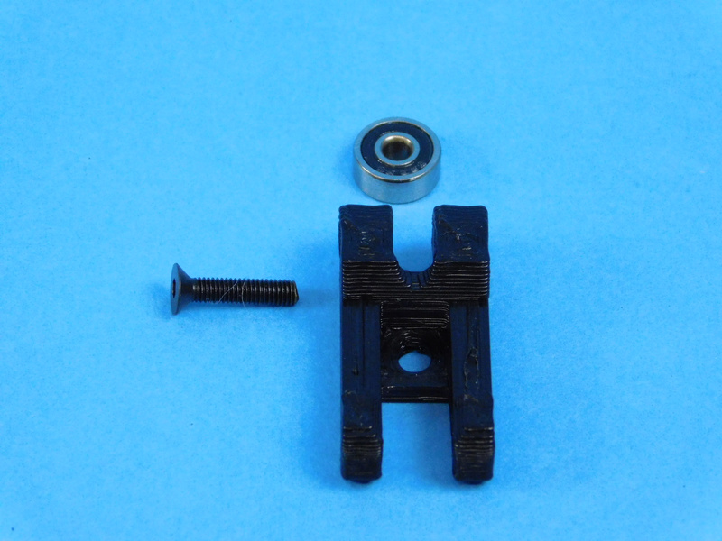
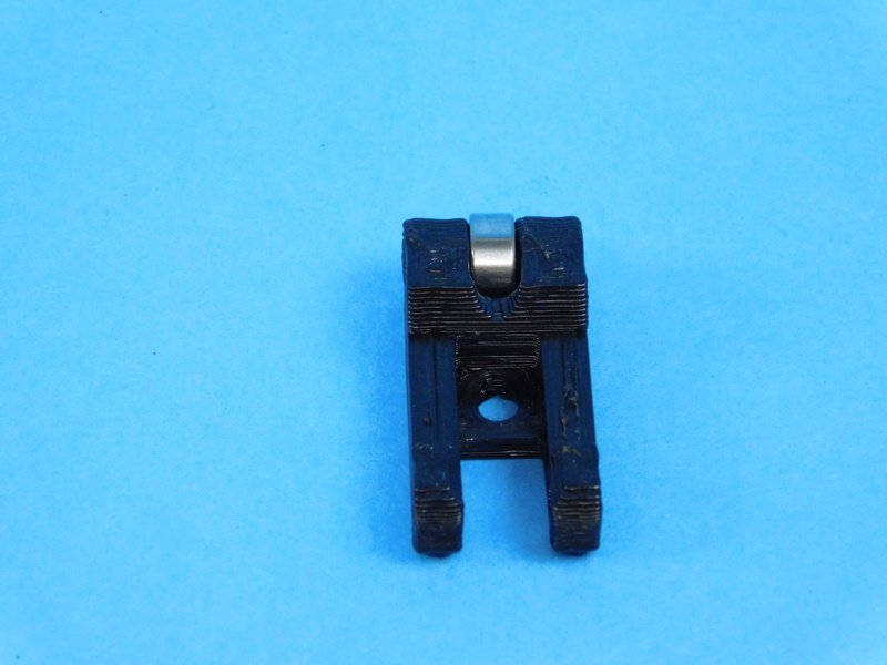
Fasten the rubber sealed bearing [HD-MS0470] to the Sensor Idler w/ Inserts [PP-IS0109] using an M3X14 FHCS HD-BT0118].
Torque to 3in*lbs
Fasten the sensor idler to the filament sensor assembly with an M3X16 SHCS [HD-BT0185] from the outside left/right.
Tighten until screw head rests against printed idler; too much tension will prevent the idler from moving properly.
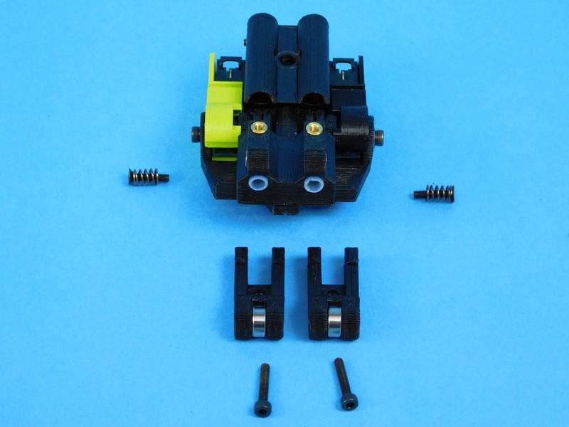
Slide one Round Compression Spring [HD-MS0471] onto an M3x14 FHCS [HD-BT0118]
Thread one through the front of each Filament Idler (2 total) and into the insert behind it.
This should not be tightened all the way.
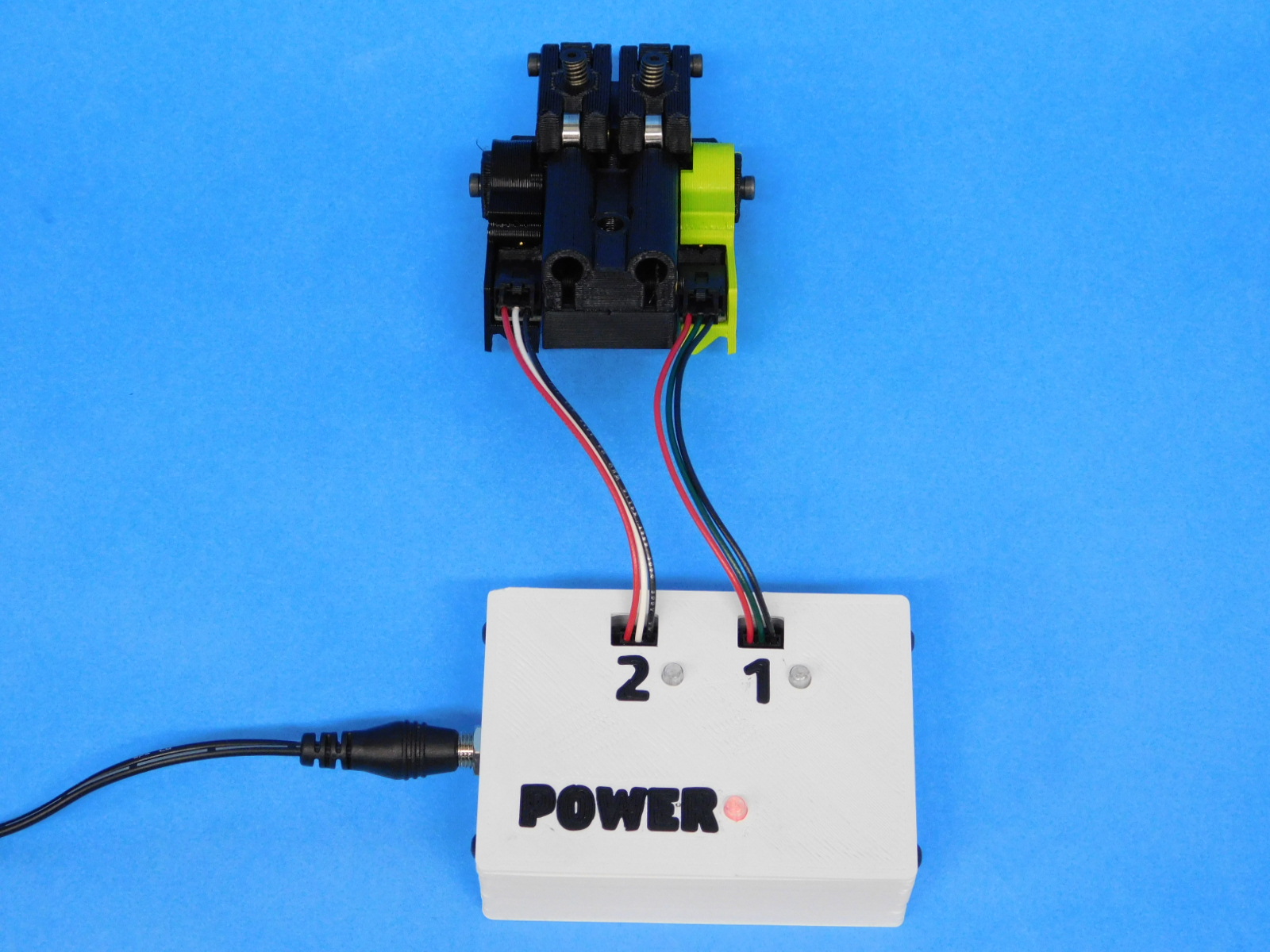
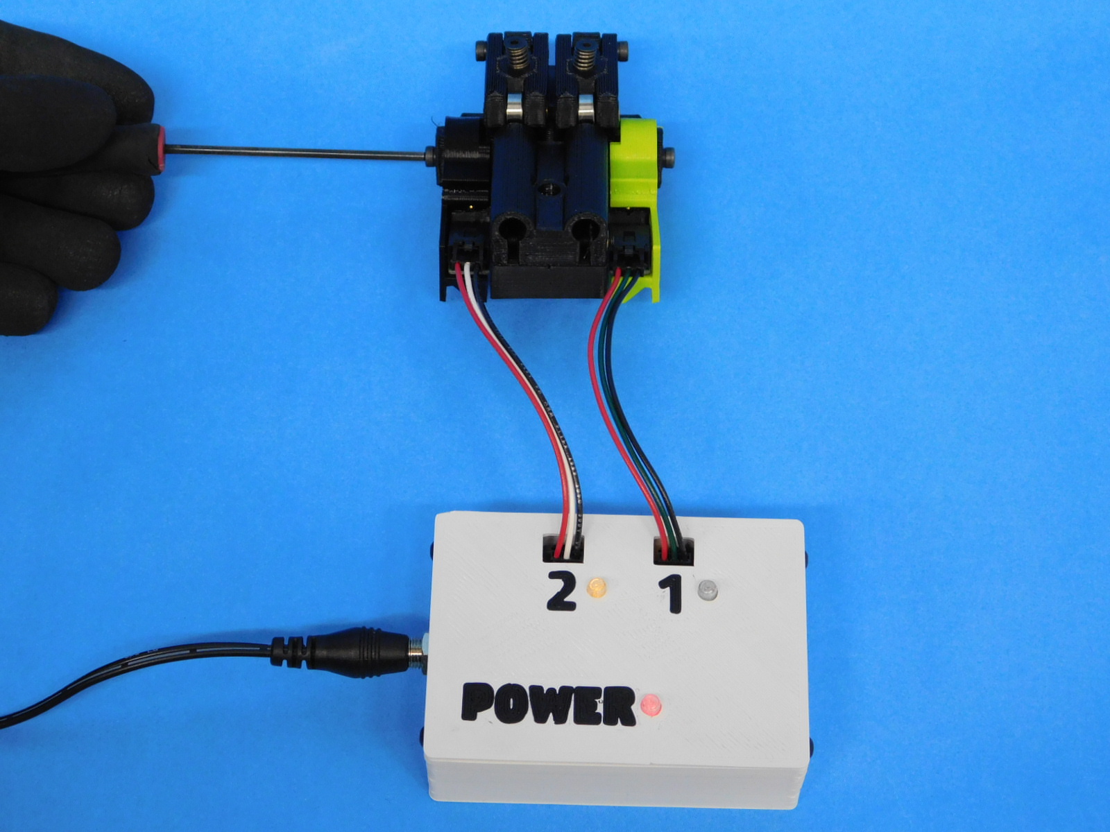
You will need a Filament Sensor Tester, plug it in to power and ensure the POWER LED is lit
Connect the connector on the green side to the test box lead labeled "1"
Connect the connector on the black side to the test box lead labeled "2"
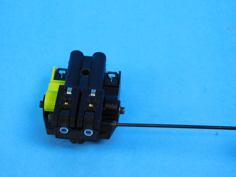
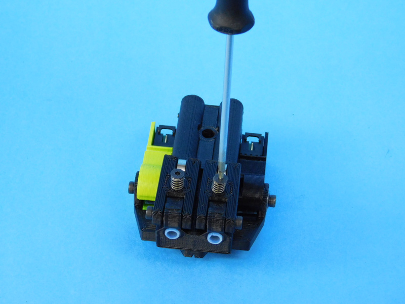
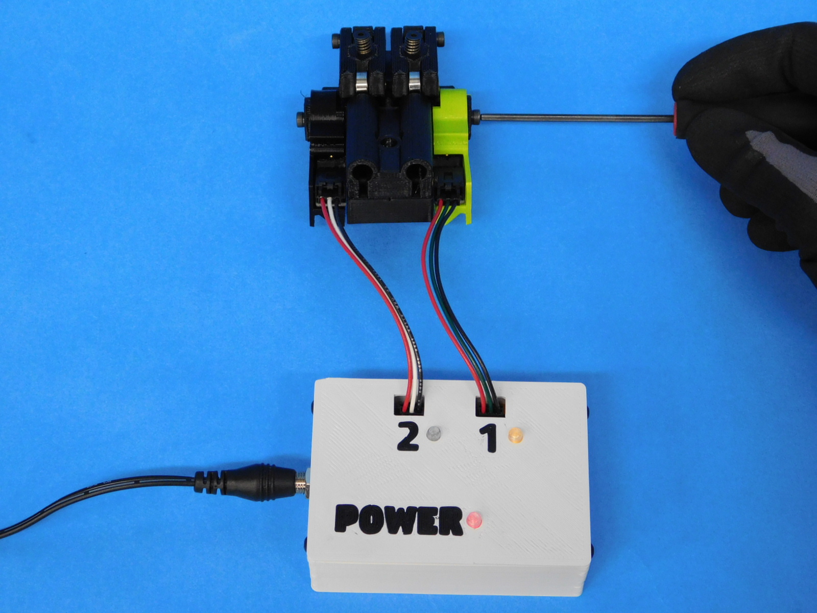
By hand or with a 2.5mm driver, spin the encoder wheels of the filament sensor individually while observing the corresponding light flashing on the test box.
Ensure the light flashes consistently for one full rotation of the encoder wheel.
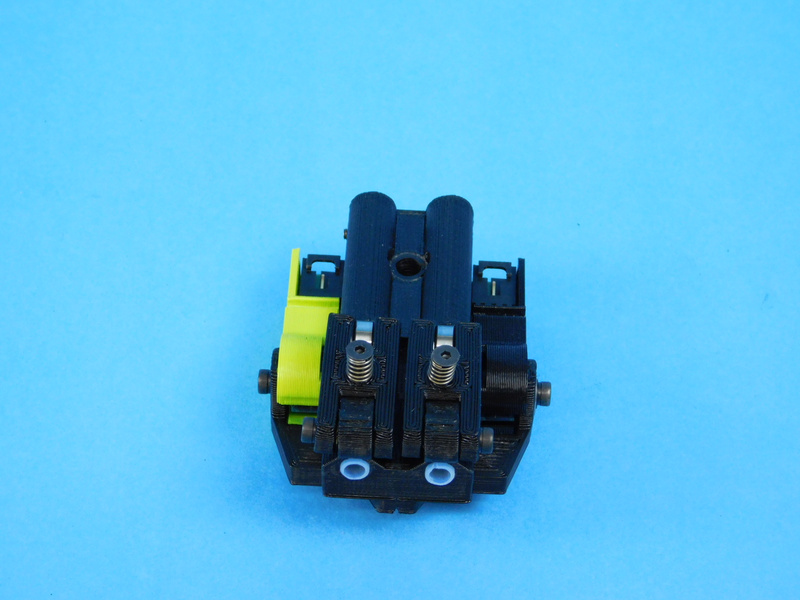
Ensure both encoder wheels spin freely without contacting (rubbing) the filament sensor board.
If both sensors respond correctly, the test is complete.
Disconnect from the filament sensor test box, and you're done!
Good job!
The final step is to complete the Quality Assurance Record.
To complete the Quality Assurance Record, verify the following:
To complete the final inspection step, another crew member must inspect the Filament Sensor and verify the Quality Assurance Record has been completed.
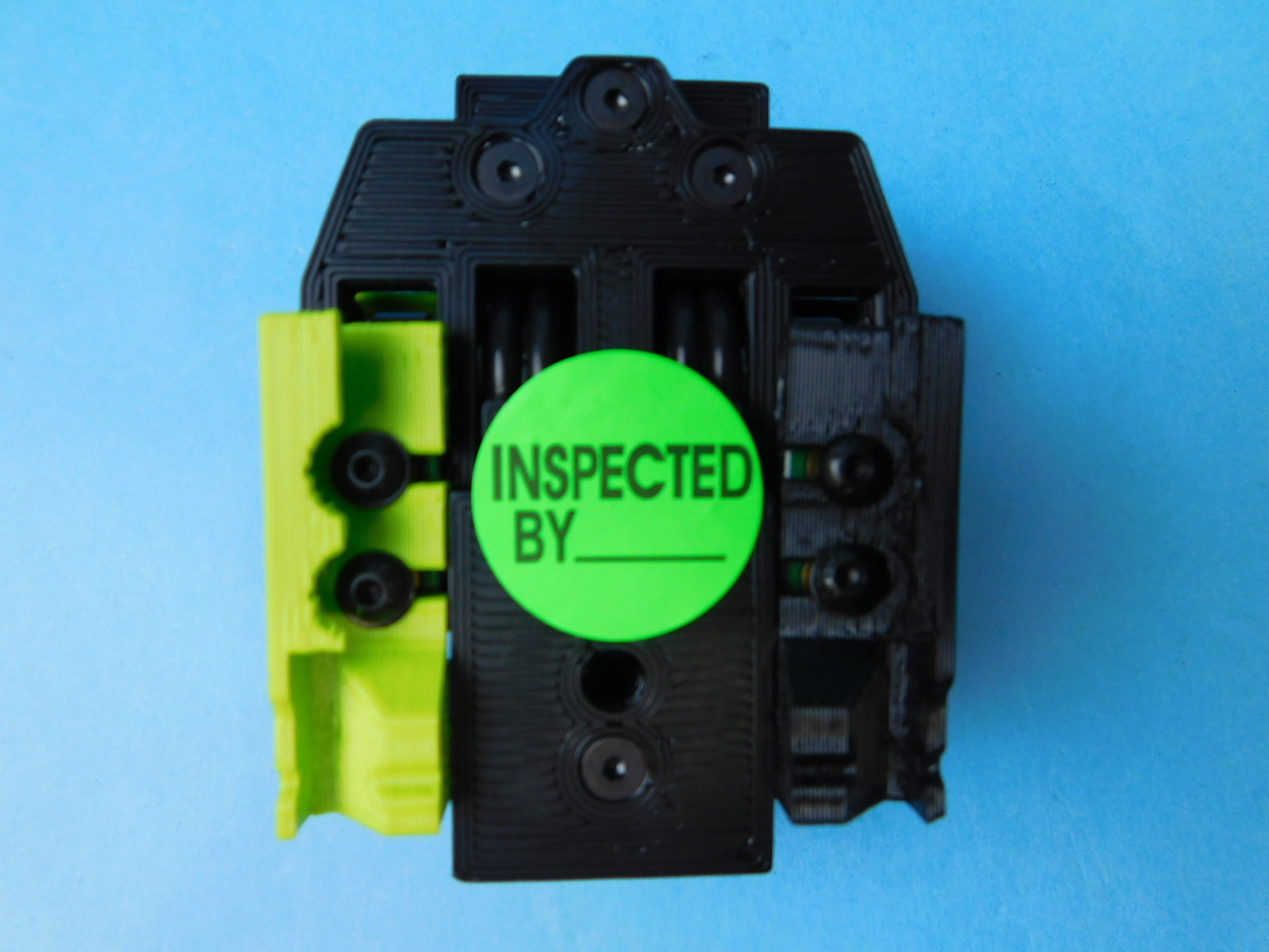
Once completed, initial the 'Inspected By" sticker and place the sticker on the back of the Filament Sensor.
Great Job! This sub-assembly is complete!