Open HardwareAssembly Instructions
Guides for installation and assembly of the LulzBot line of products made by Aleph Objects, Inc.
Guides for installation and assembly of the LulzBot line of products made by Aleph Objects, Inc.
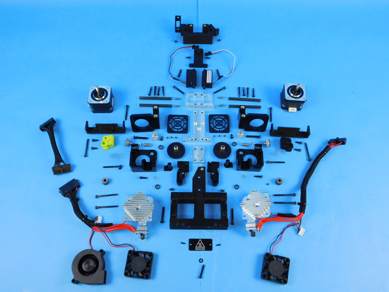
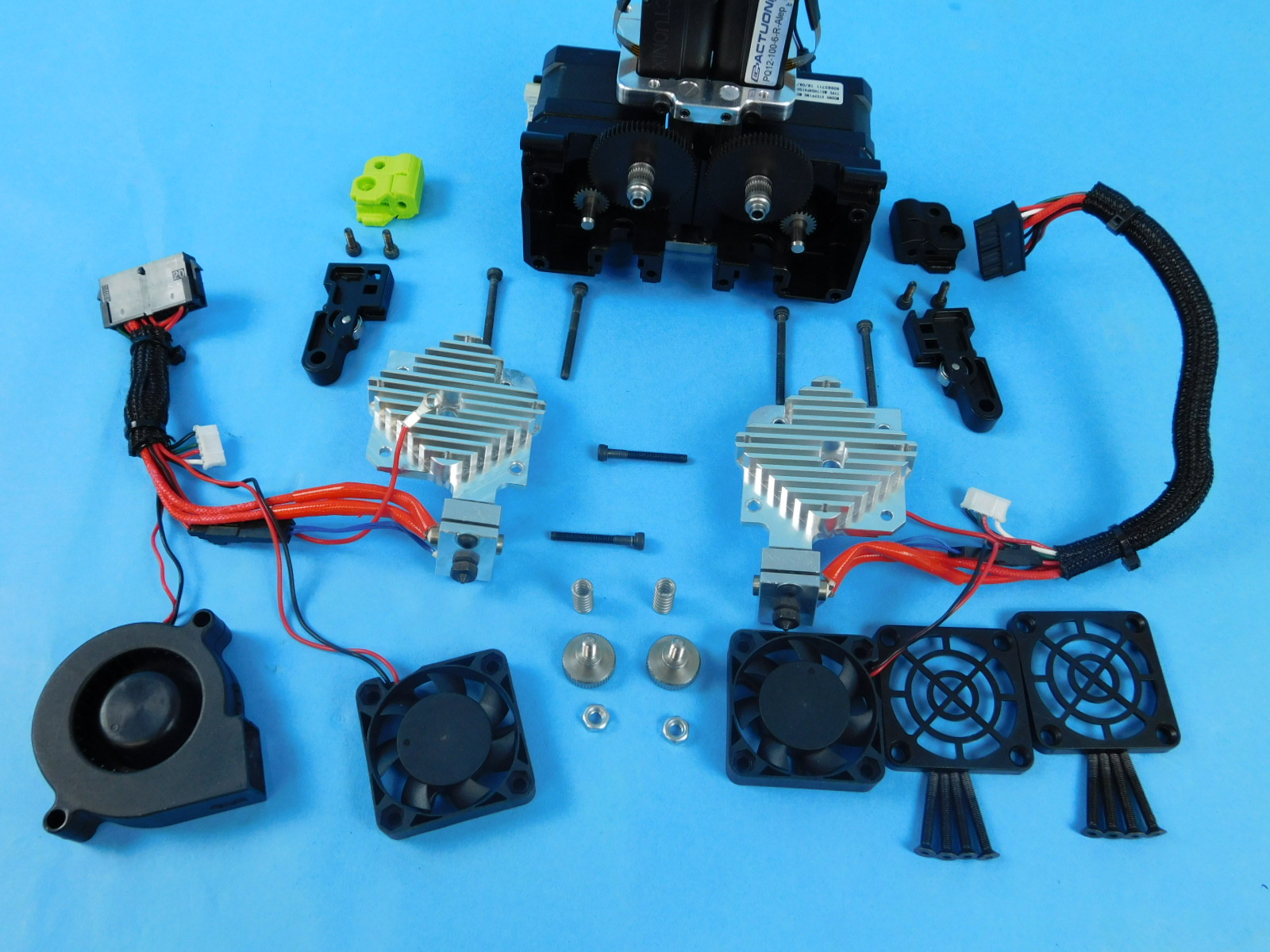
Gather all the required materials:
2x- [HD-BT0235] - M2x0.4 BHCS
4x- [HD-BT0041] - M3x25 SHCS
6x- [HD-BT0042] - M3x30 SHCS
6x- [HD-BT0043] - M3x35 SHCS
4x- [HD-BT0157] - M3x8 SHCS
4x- [HD-BT0128] - M3x6 FHCS
2x- [HD-BT0146] - M3x12 BHCS
8x- [HD-BT0162] - M3x4 Set screw
3x- [HD-BT0171] - M3x20 BHCS
2x- [HD-BT0197] - M4 Thumb screw
8x- [HD-BT0204] - M3x22 FHCS
2x- [HD-MS0430] - Idler spring
4x- [HD-MS0446] - Bearing
2x- [HD-NT0011] - M4 Nut
2x- [HD-WA0027] - Lock washer
1x- [HD-WA0038] - M3 washer
4x- [HD-BT0136] - M3x12 SST FHCS
4x- [HD-BT0137] - M3x8 BHCS
2x- [HD-BT0161] - M4x25 BHCS
1x- [PP-IS0085] - Blower shroud
1x- [PP-IS0084] - Actuator mount
1x- [PP-IS0083] - Idler clamp right
1x- [PP-IS0082] - Idler clamp left
1x PP-GP0470 - Cable channel E1
1x PP-GP0471 - Cable channel E2
1x- [PP-IS0081] - Actuator cover
1x- [EL-HR0145] - E1 Extension harness
1x- [EL-HR0165] - Standard Aero Extruder Harness
1x- [EL-HR0166] - Mirrored Aero Extruder Harness
2x- [EL-HR0170] - Fan guard
2x- [EL-MT0040] - Half height stepper motor
2x- [EL-MS0536] - PQ12-100-6-R-Alep, Micro Linear Servo w/custom cable and connector
1x- [PP-FP0135] - Mirrored Idler lever
1x- [PP-FP0136] - Mirrored filament guide
2x- [PP-FP0154] - Extruder hobb
1x- [PP-FP0158] - Standard filament guide
1x- [PP-FP0162] - Standard idler lever
1x- [PP-MP0204] - Mirrored body
2x- [PP-MP0282] - Steel pinion gear
1x- [PP-MP0233] - Standard body
4x- [HD-RD0070] - 6mm smooth rod
1x- [PP-MP0228] - Top rod mount
1x- [PP-MP0229] - Back plate
2x- [PP-MP0230] - Actuator connector
1x- [PP-MP0231] - Bottom plate
2x- [PP-MP0232] - Ambidextrous motor mount
2x- [EL-MS0536] - Micro linear servo
1x- [DC-LB0175] - Caution Hot tag
3x- [HD-MS0058] - Ziptie
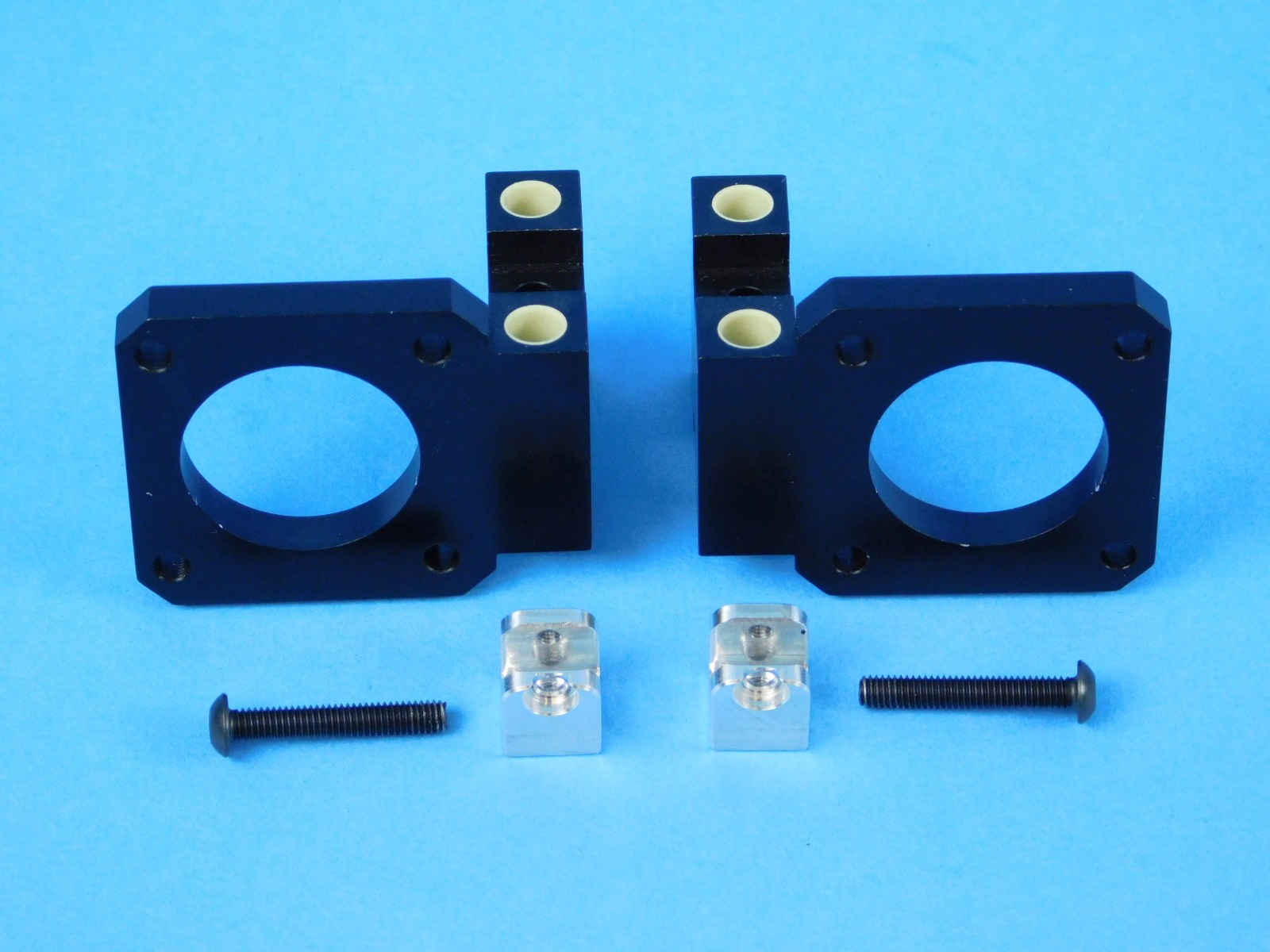
Materials:
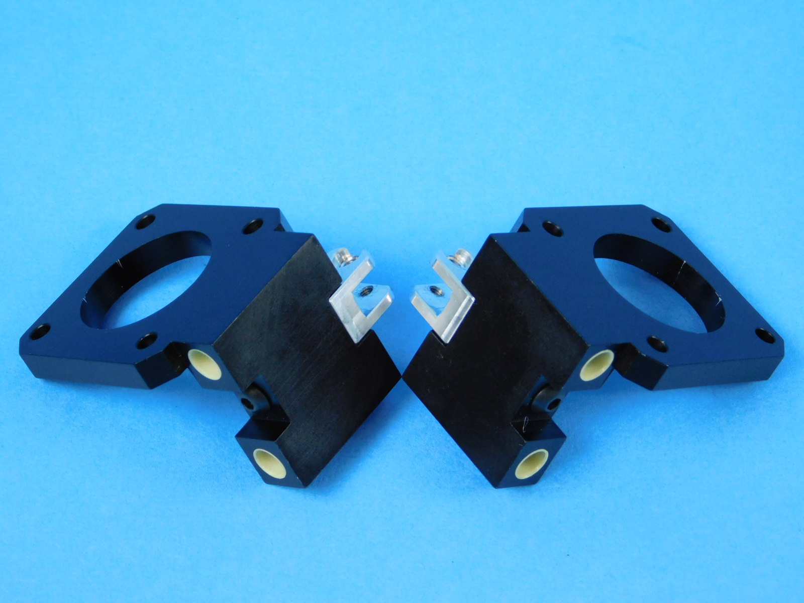
2x- [PP-MP0232] - Motor Mount Ambidextrous, Machined
2x- [PP-MP0230] - Actuator Connector
2x- [HD-BT0161] - M4x25 BHCS
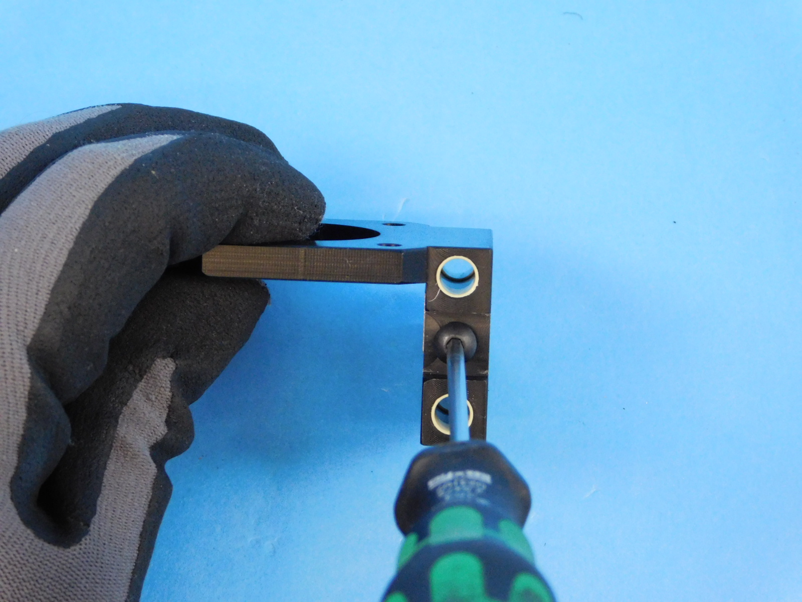
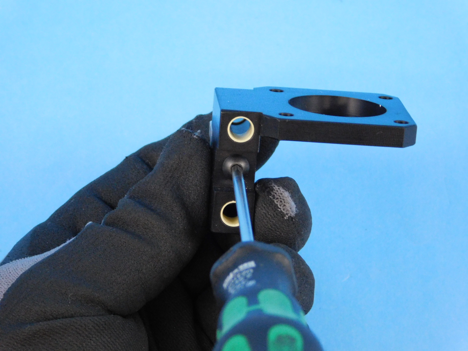
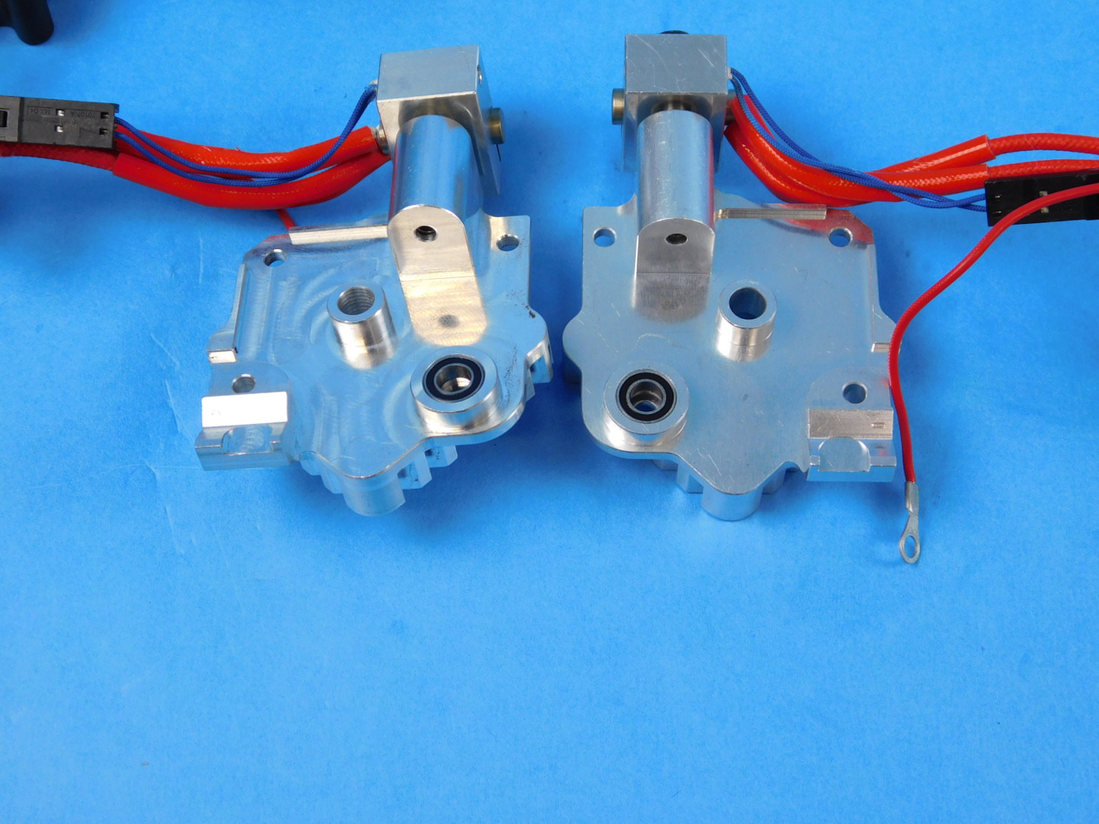
Orient the motor mounts ensure the threads of the actuator connector on top of the motor mount, are towards the linear bearing holes on the back of the part. Using [HD-BT0161], fasten the Actuator Connector to the motor mount coming up from the bottom.
Torque to 5in*lbs
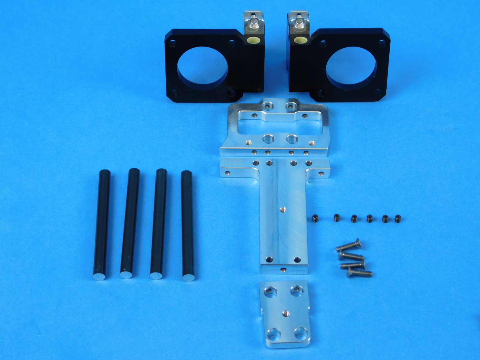
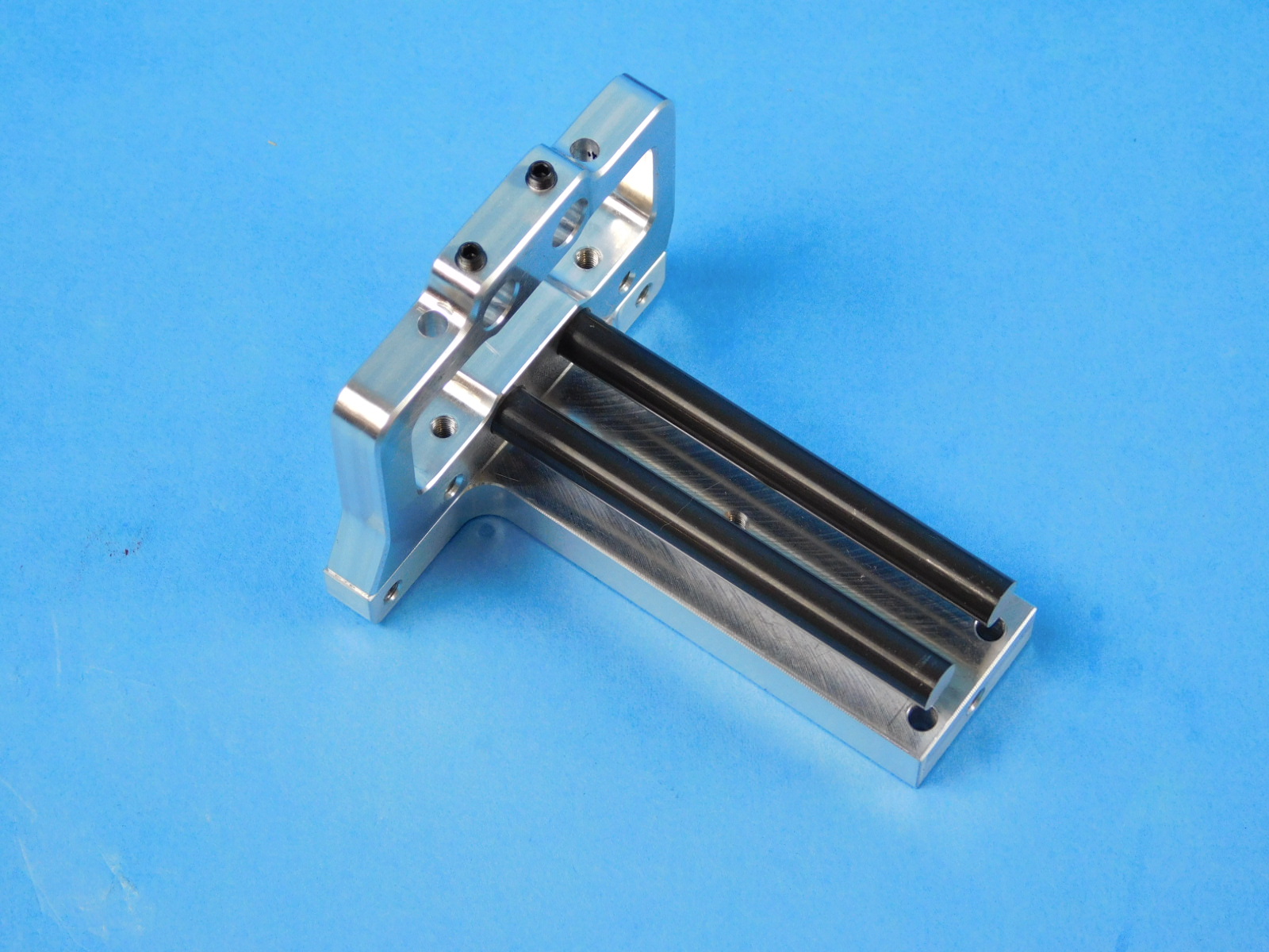
Materials:
Assemblies from step 3
4x- [HD-RD0070] - 6mm smooth rod
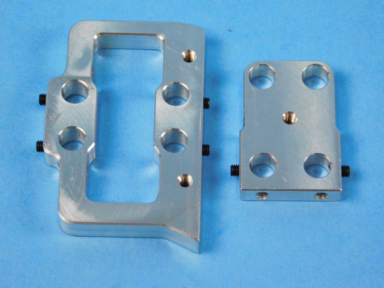
1x- [PP-MP0228] - Top rod mount
1x- [PP-MP0229] - Back plate
1x- [PP-MP0231] - Bottom plate
4x- [HD-BT0136] - M3x12 SST FHCS
6x- [HD-BT0162] - M3x4 Set screw
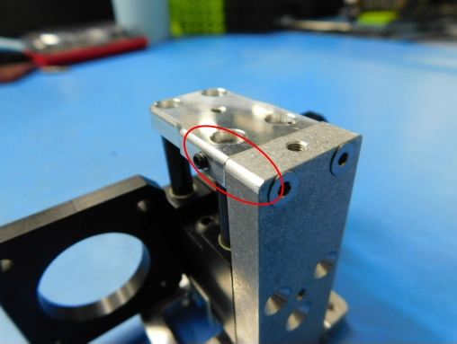
Ensure the bottom plate and top rod mount have HD-BT0162 installed but are not deep enough to scratch the 6mm smooth rod during installation.
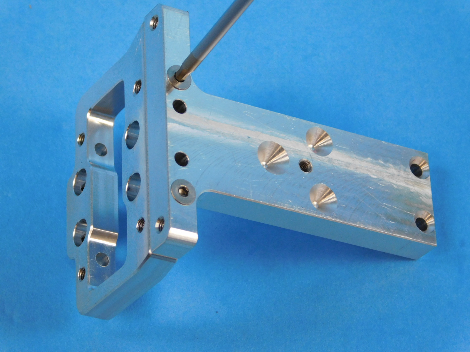
Fasten top rod mount to the back plate using HD-BT0136.
Install the assemblies from step 3 and secure the smooth rods in place by tightening two HD-BT0162.
Install the Bottom Plate [PP-MP0229], using 2x - HD-BT0136 screws.
Note Bottom Plate orientation: The rounded edge on the Bottom Plate should be flush with the rounded edge on the Back Plate.
Torque HD-BT0136 to 5in*lbs
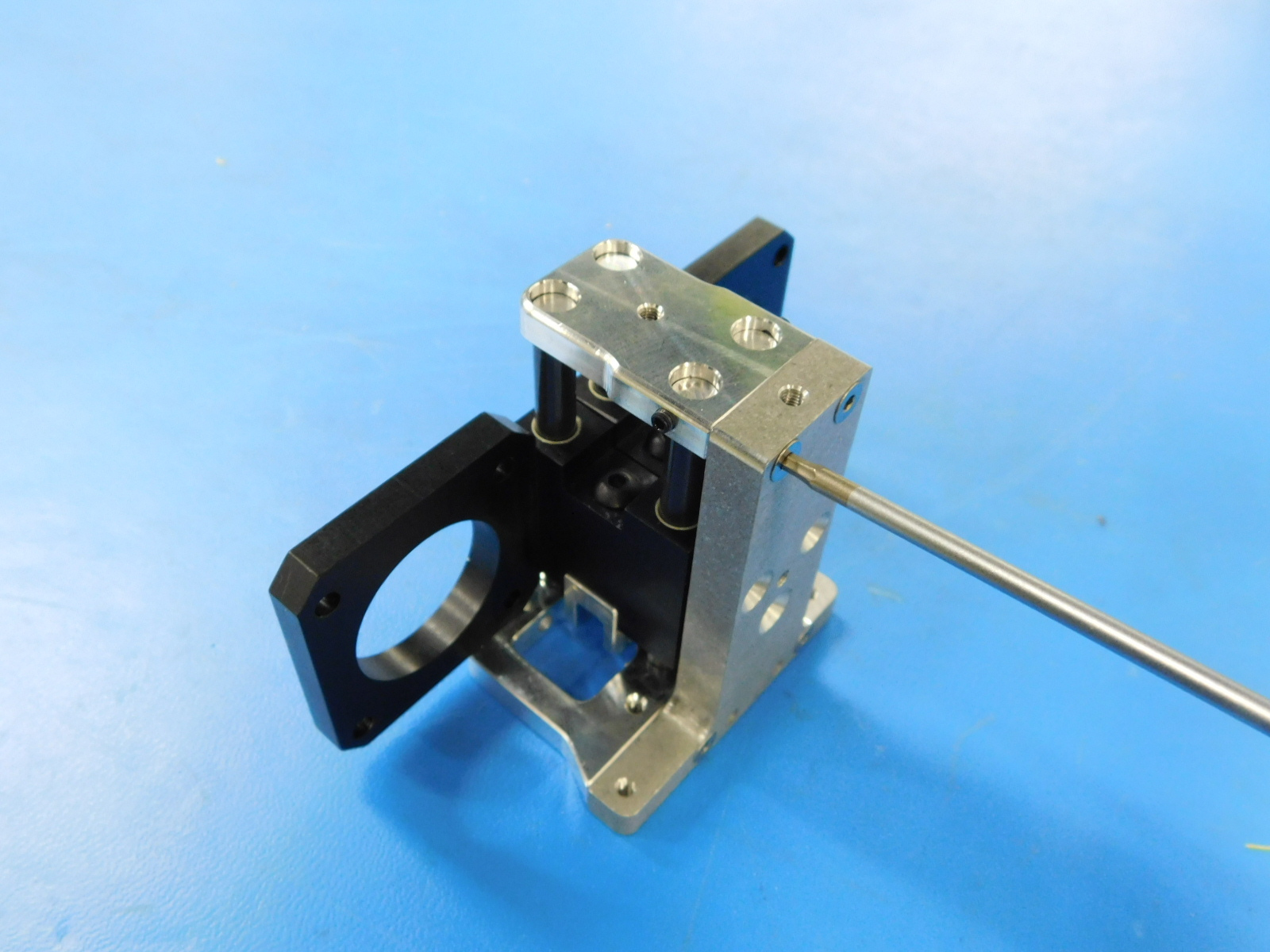
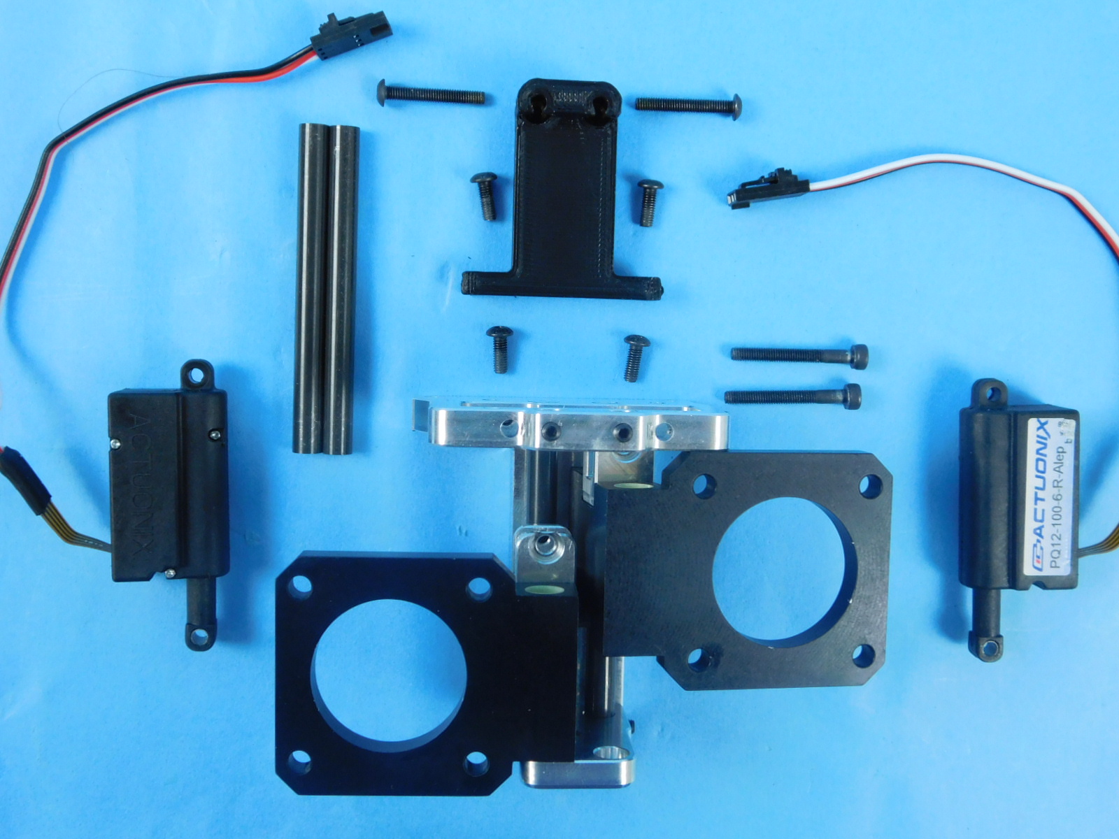
Materials:
Assembly from step 4
2x- [HD-BT0041] - M3x25 SHCS
4x- [HD-BT0137] - M3x8 BHCS Torque to 3in*lbs
2x- [HD-BT0171] - M3x20 BHCS
1x- [PP-IS0084] - Actuator mount
2x- [EL-MS0356] - PQ12-100-6-R-Alep, Micro Linear Servo w/custom cable and connector
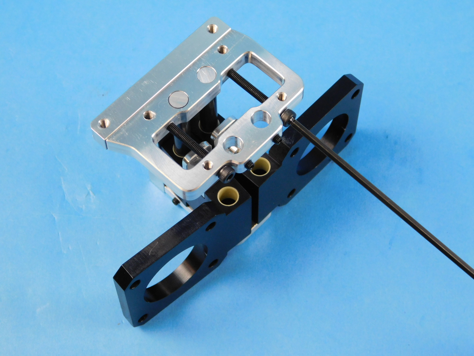
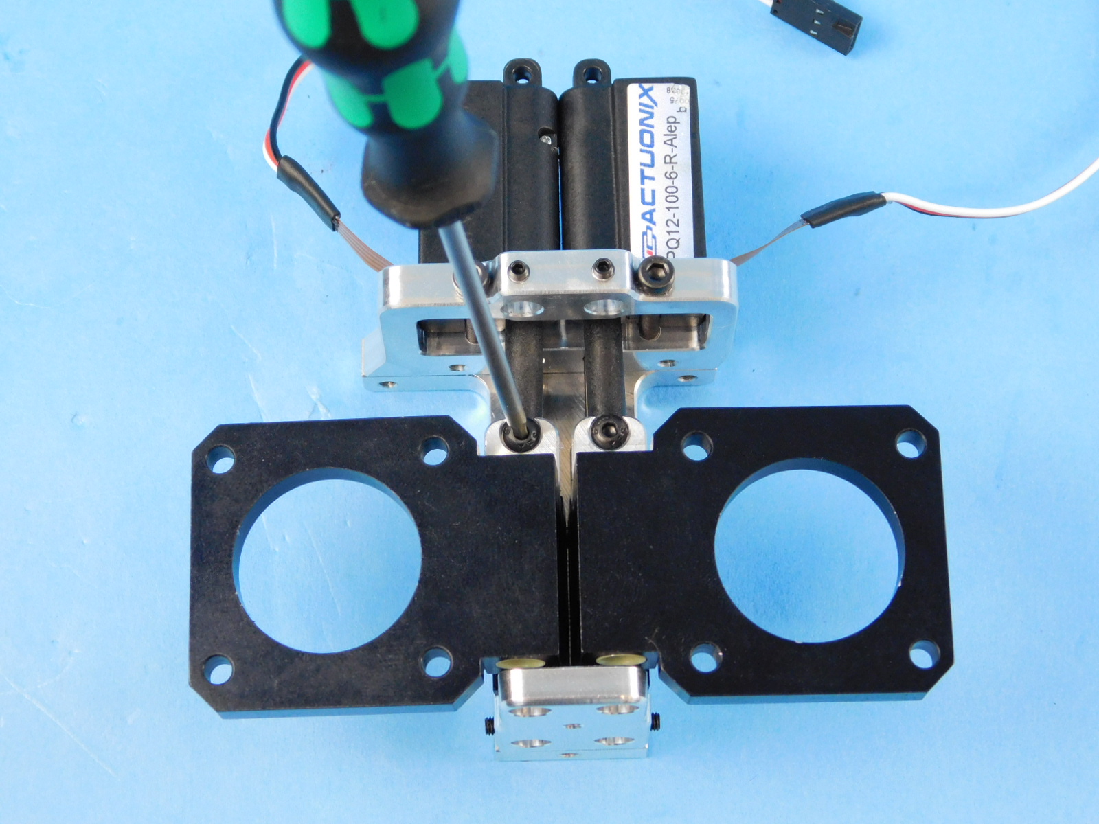
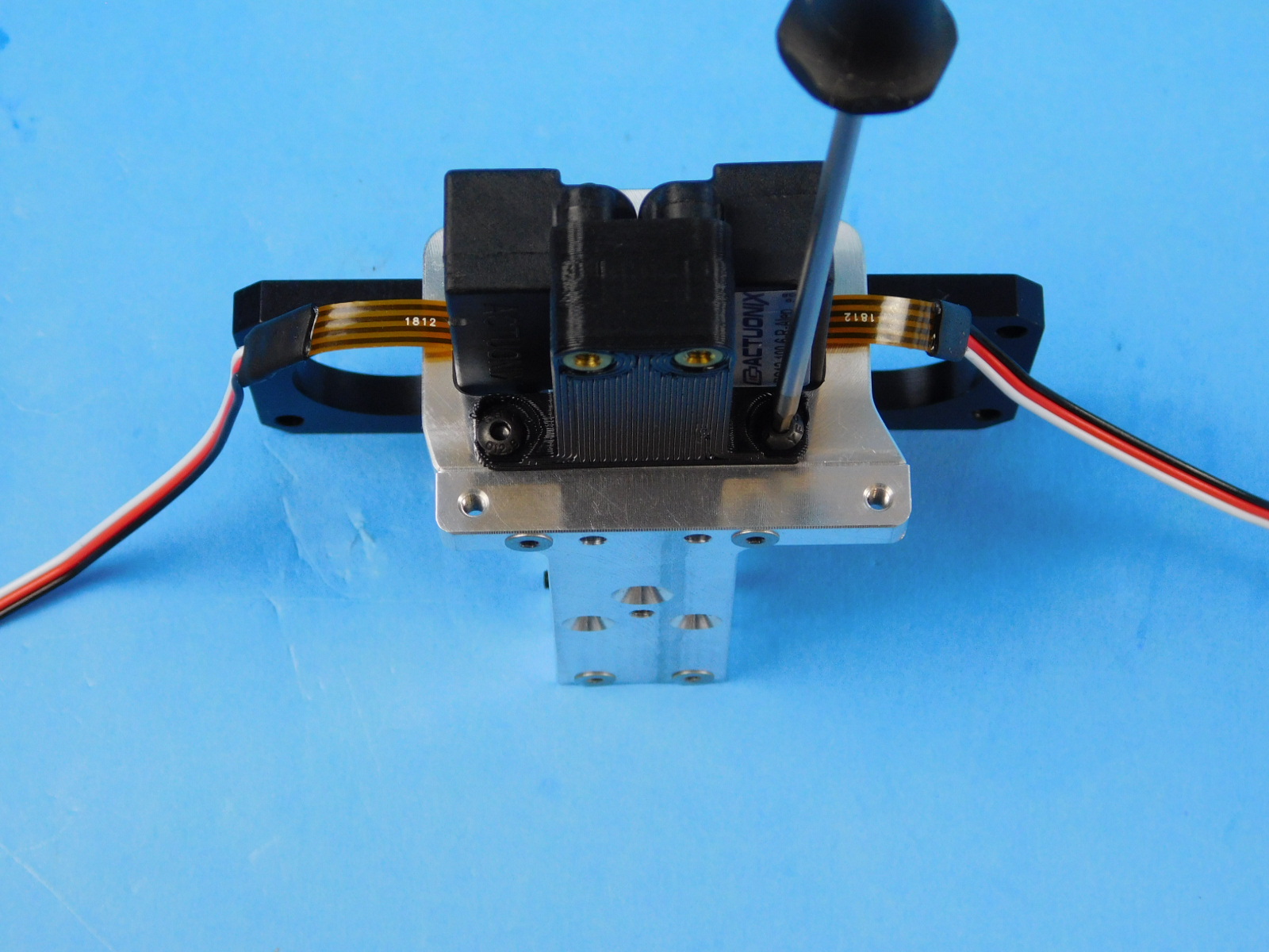
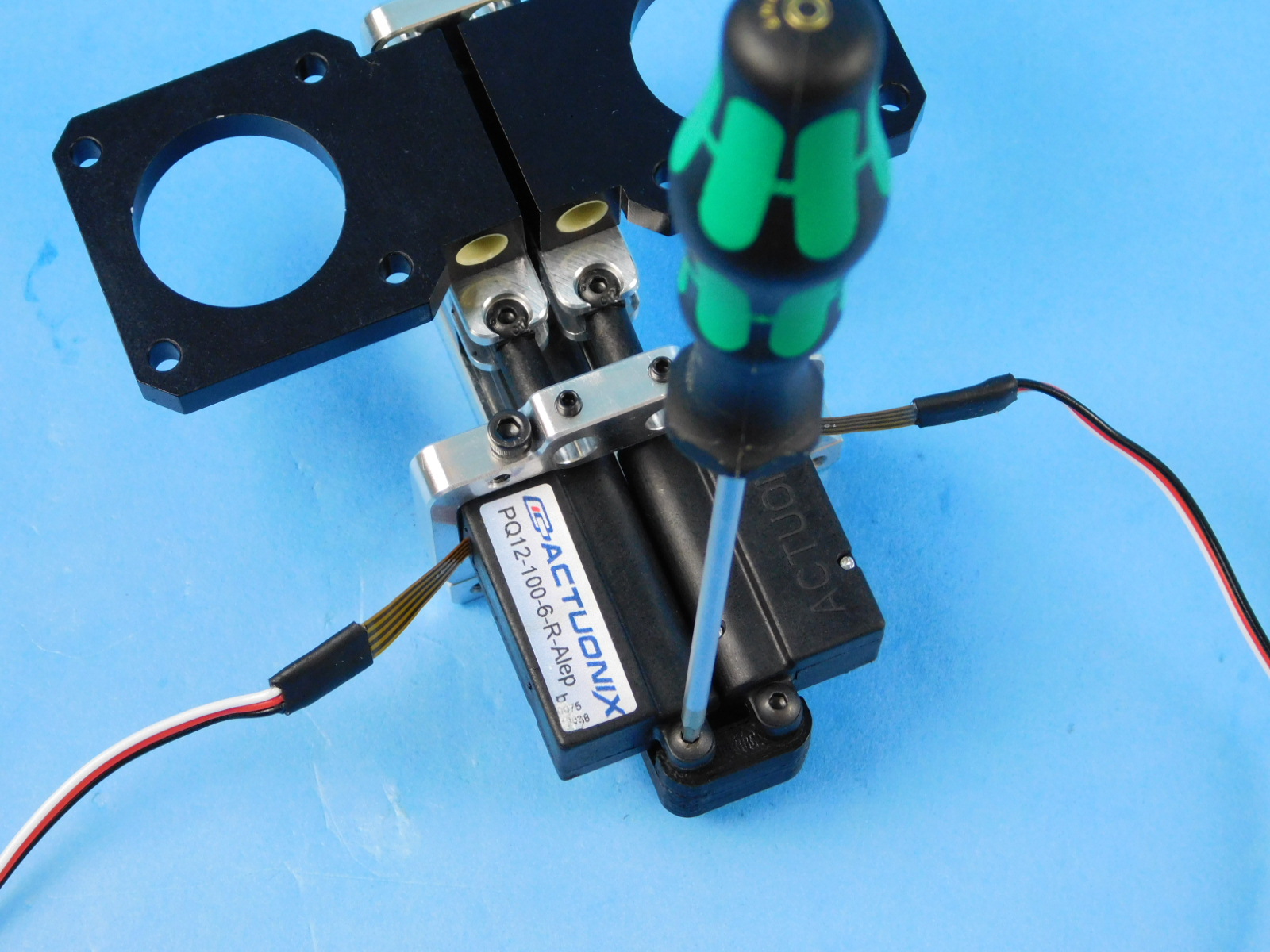
Start by fastening the two HD-BT0041 into the assembly from step 4. Tighten finger tight. Take care not to over-tighten
Slide the two EL-MS0356 into the assembly so that the HD-BT0041's are supporting in the groove of the part. Fasten the actuators to the PP-MP0230 installed on step 3, using two HD-BT0137's.
Secure the actuator mount PP-IS0084 to the top rod mount using the remaining two HD-BT0137's.
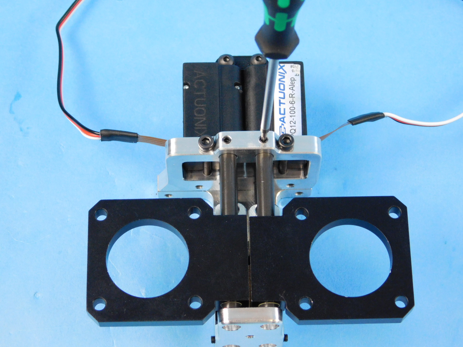
Flip the assembly so the back plate is on the table, fasten the actuators to the actuator mount using the two HD-BT0171's.
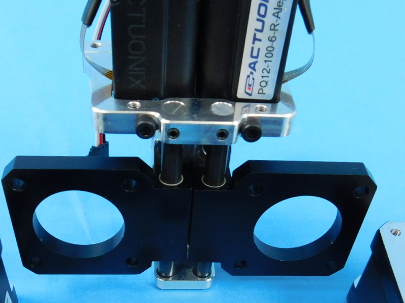
Insert the two HD-RD0070 6mm smooth rods into the assembly and double check that all the set screws are just finger tight. Take care not to over-tighten.
Ensure the smooth rods are flush with the top plate.
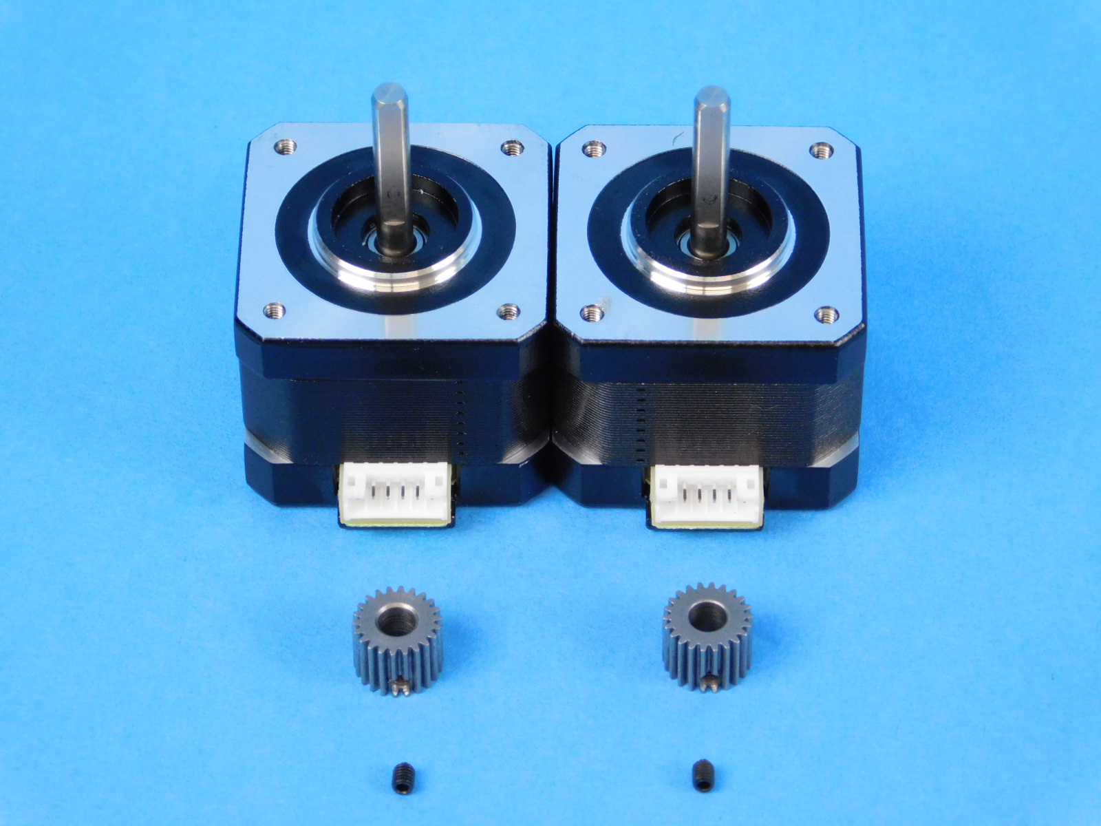
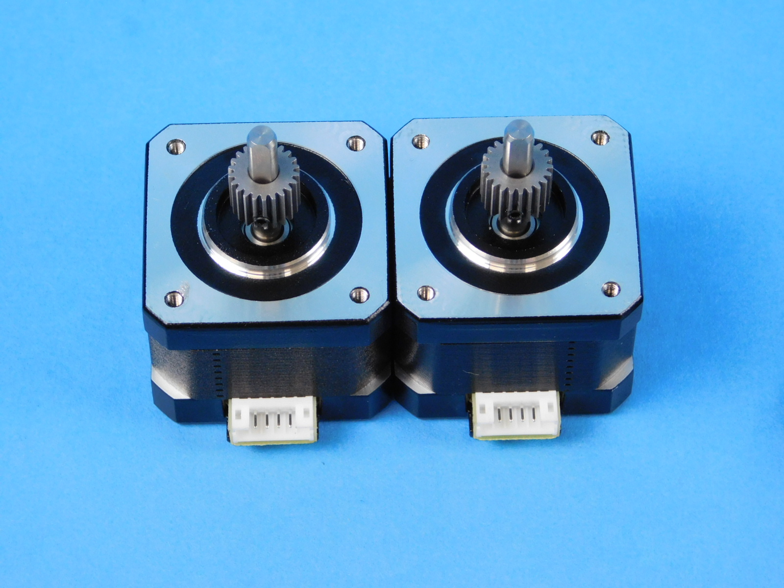
Materials:
2x- [EL-MT0040] - NEMA 17 Half Height Stepper Motor
2x- [PP-MP0282] - E3D Aero Steel Pinion Gear
2x- [HD-BT0162] - Alloy Steel Cup Point Set Screw M3x4
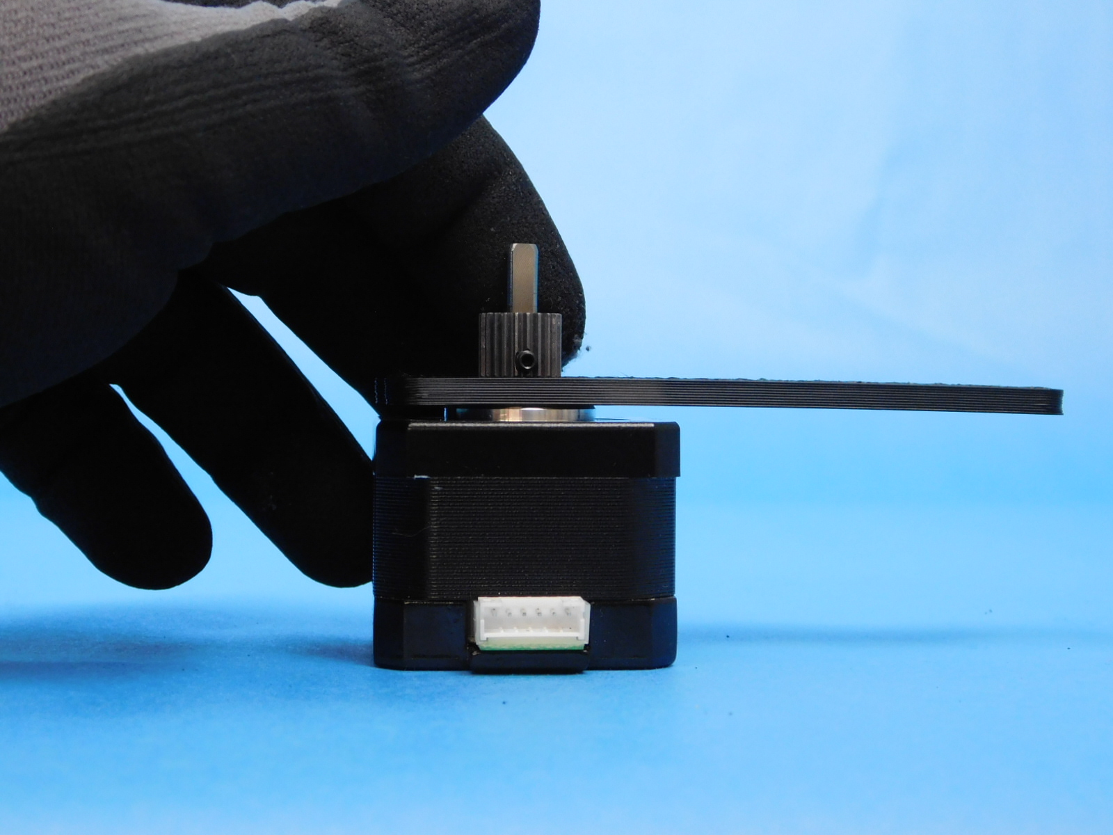
Using the Q Dual Pinion spacing jig , line up the set screw with the flat of the shaft on the motor.
Torque to 3 in*lbs.
Repeat for the second motor.
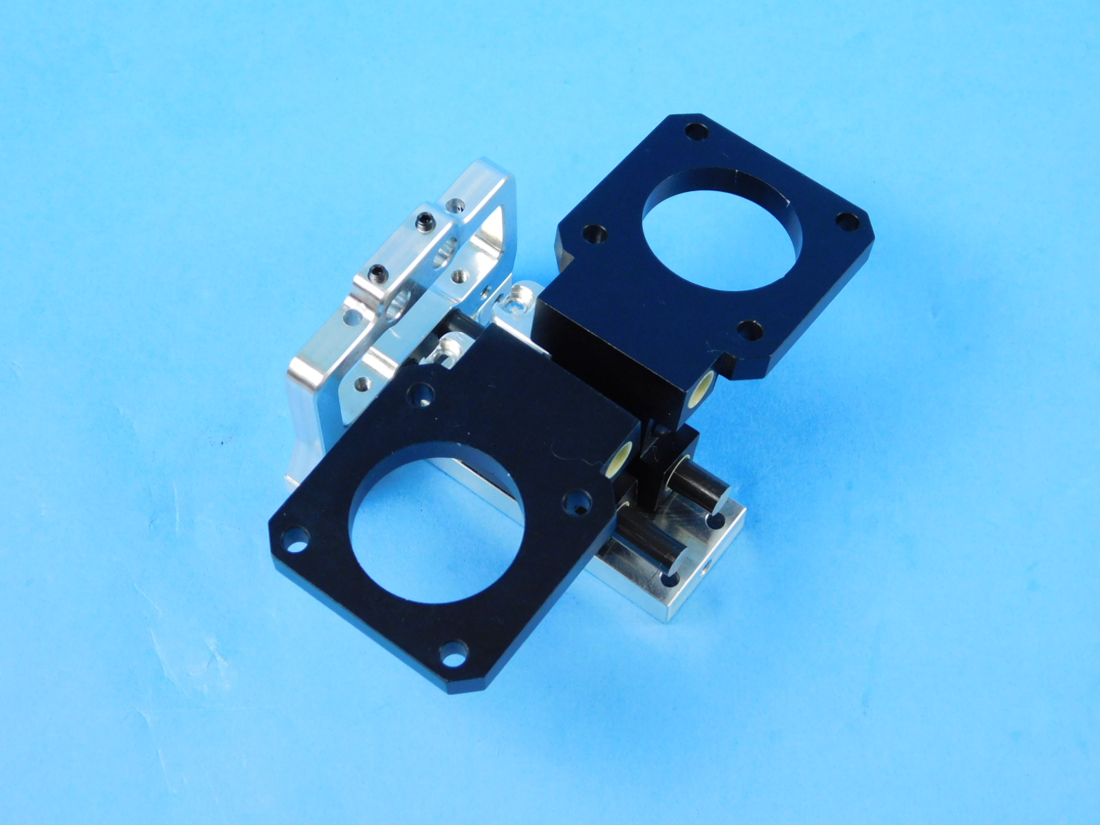
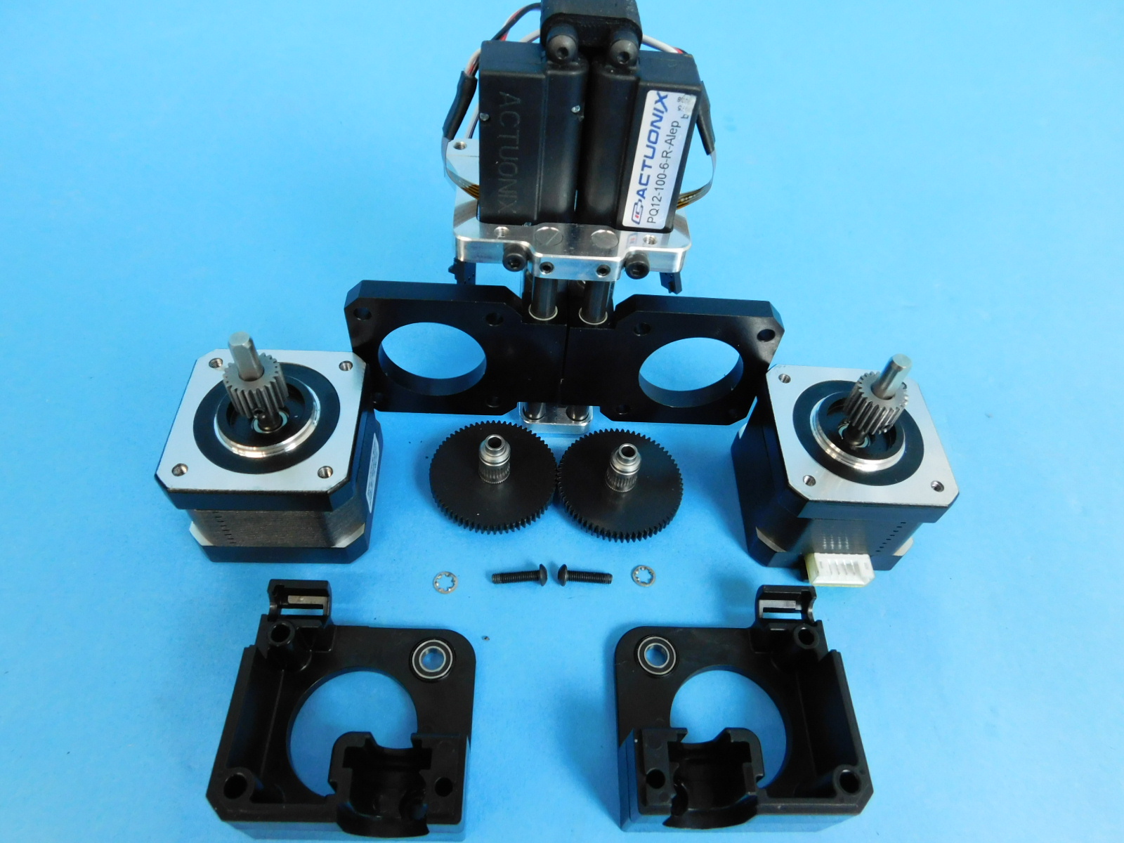
Materials:
Assembly from step 5
Assembly from step 2
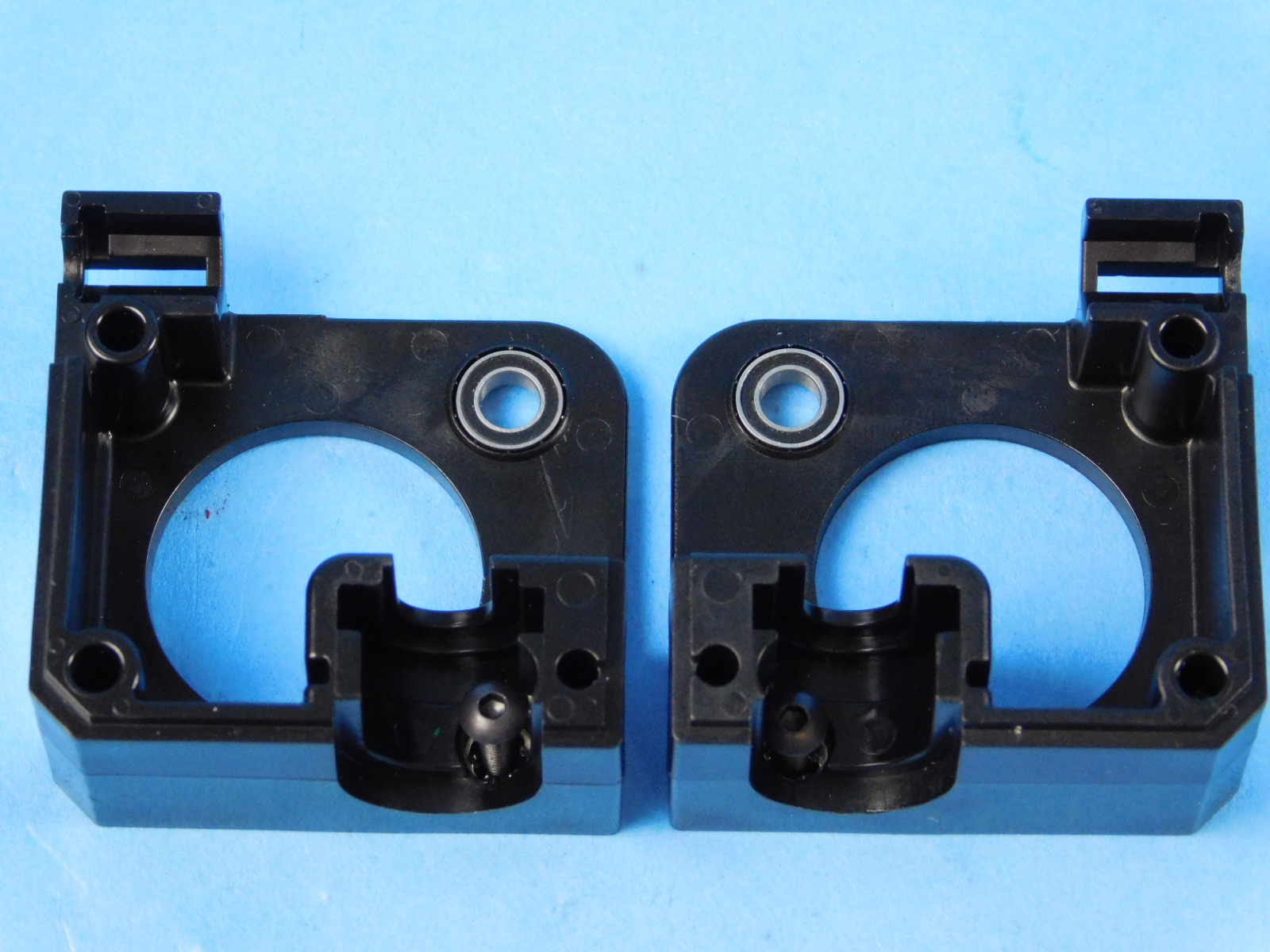
1x- [PP-MP0233] - Standard body
1x- [PP-MP0204] - Mirrored body
2x- [HD-WA0027] - Lock washer
2x- [HD-BT0146] - M3x12 BHCS Torqued to 5in* lbs
2x- [HD-MS0446] - Bearing
2x- [PP-FP0154] - Extruder hobb
Start by installing the two HD-MS0446, two HD-BT0146, and two HD-BT0146 into both PP-MP0233 and PP-MP0204.
Start by installing the two HD-MS0446, two HD-BT0146, and two HD-BT0146 into both PP-MP0233 and PP-MP0204.
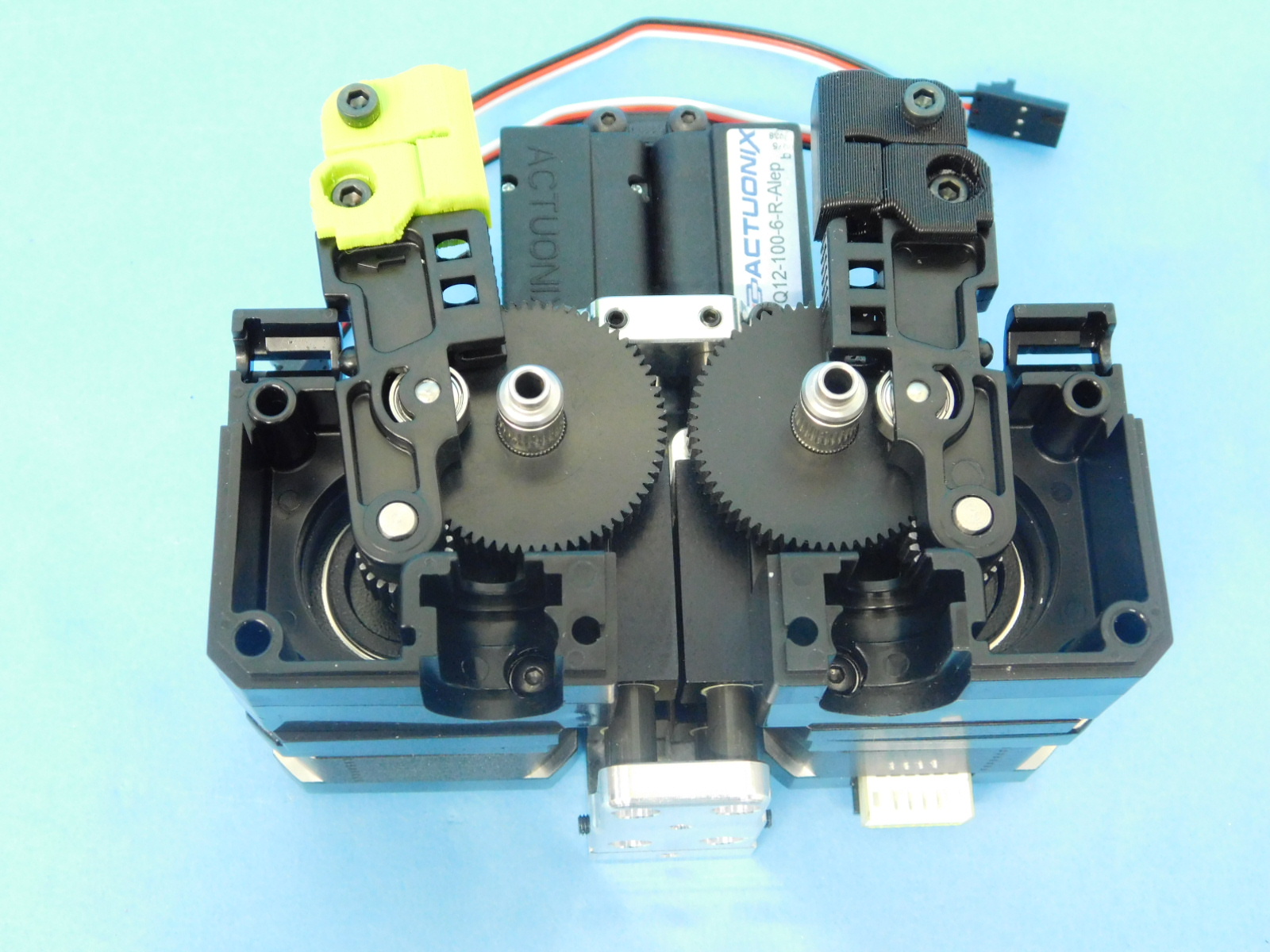
Next insert the extruder hobbs into the bearings on the extruder bodies
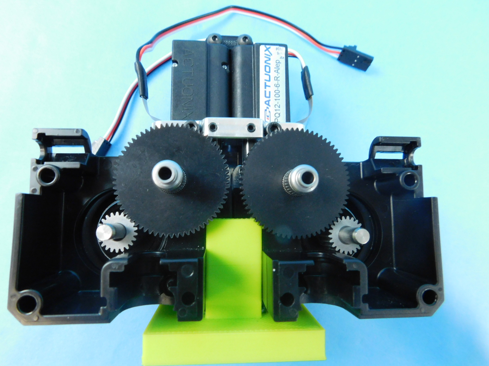
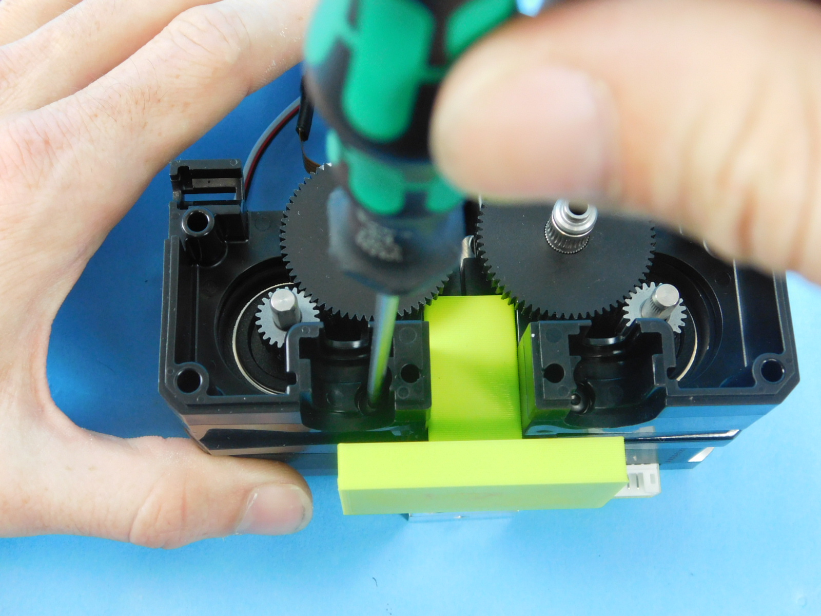
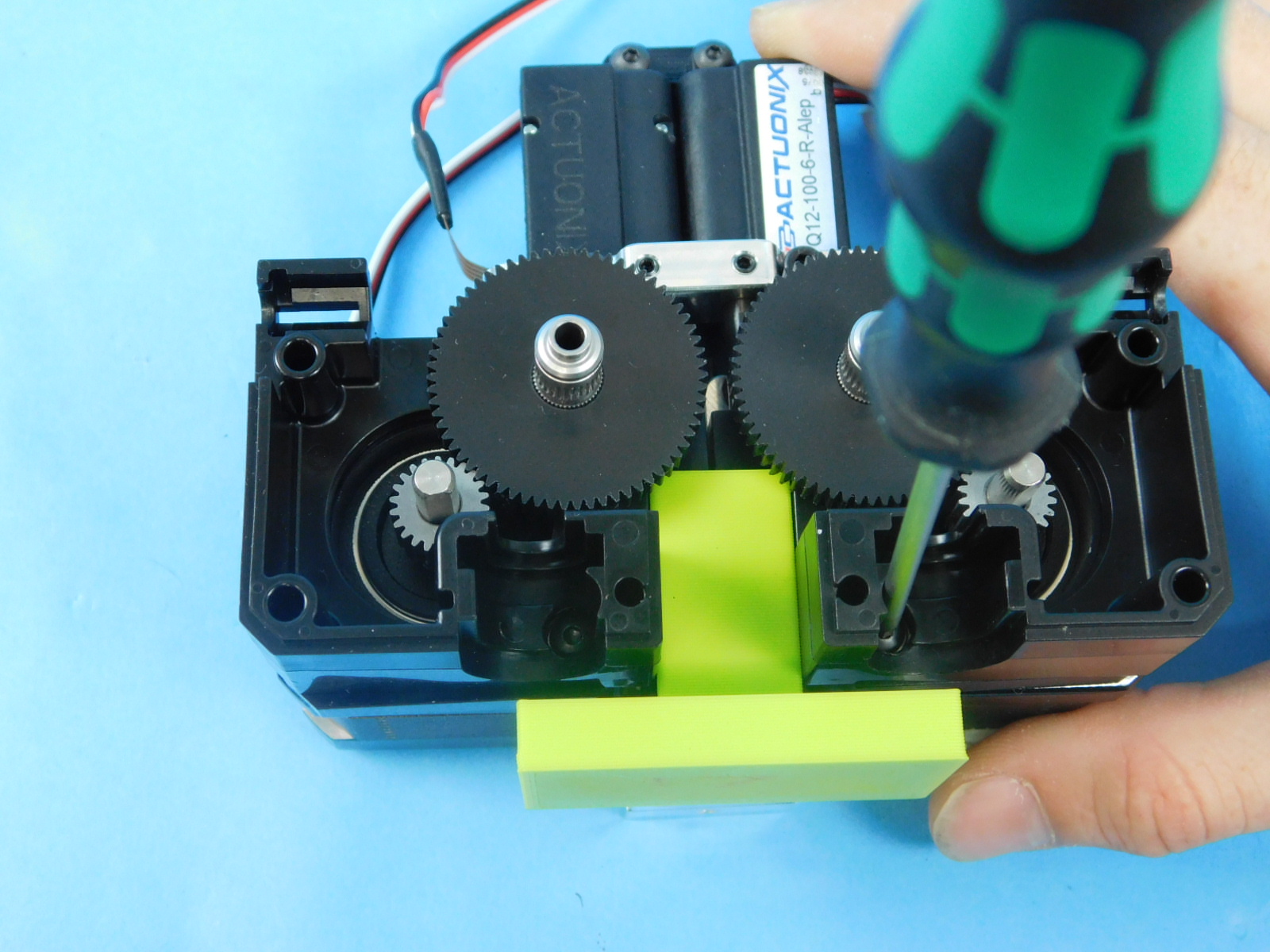
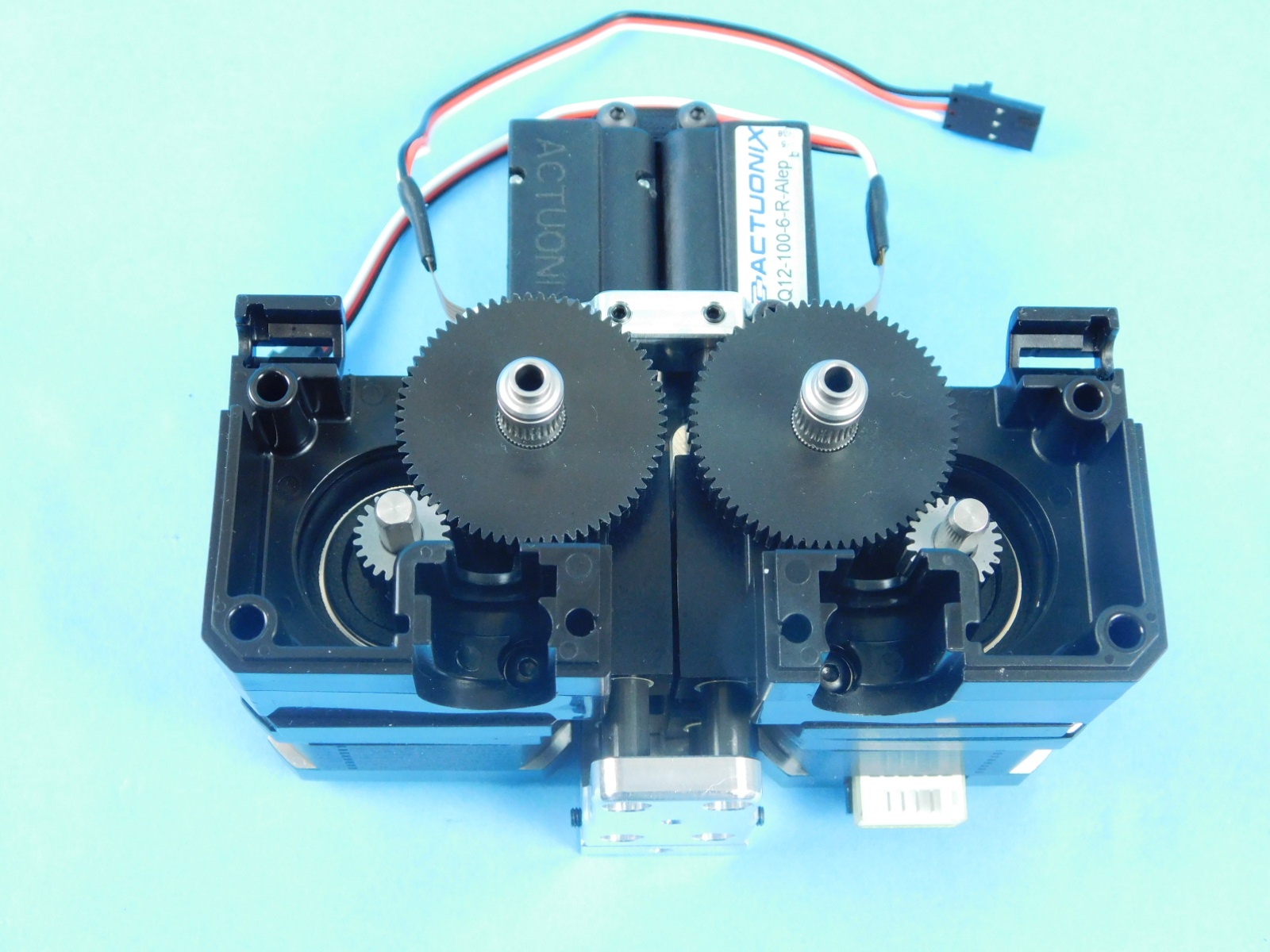
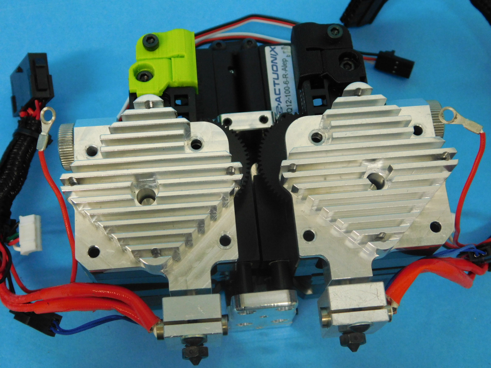
Orient the motors so when facing the front the left motor connection feeds to the left and the right motor connection feeds down. Insert the jig between the two extruder bodies. Then while holding the motor up, so that the gears mesh together, fasten the extruder bodies to the motors with the assembly from step 5 sandwiched between the two. Torque to 5in lbs
Materials:
Assembly from step 6
2x- [HD-BT0041] - M3x25 SHCS
4x- [HD-BT0043] - M3x35 SHCS
4x- [HD-BT0157] - M3x8 SHCS
2x- [HD-BT0197] - M4 Thumb screw
8x- [HD-BT0204] - M3x22 FHCS
2x- [HD-MS0430] - Idler spring
2x- [HD-MS0446] - Bearing
2x- [HD-NT0011] - M4 Nut
1x- [PP-IS0083] - Idler clamp right
1x- [PP-IS0082] - Idler clamp left
1x- [EL-HR0165] - Standard Aero Extruder Harness
1x- [EL-HR0166] - Mirrored Aero Extruder Harness
2x- [EL-HR0170] - Fan guard
1x- [PP-FP0135] - Mirrored Idler lever
1x- [PP-FP0136] - Mirrored filament guide
2x- [PP-FP0154] - Extruder hobb
1x- [PP-FP0158] - Standard filament guide
1x- [PP-FP0162] - Standard idler lever
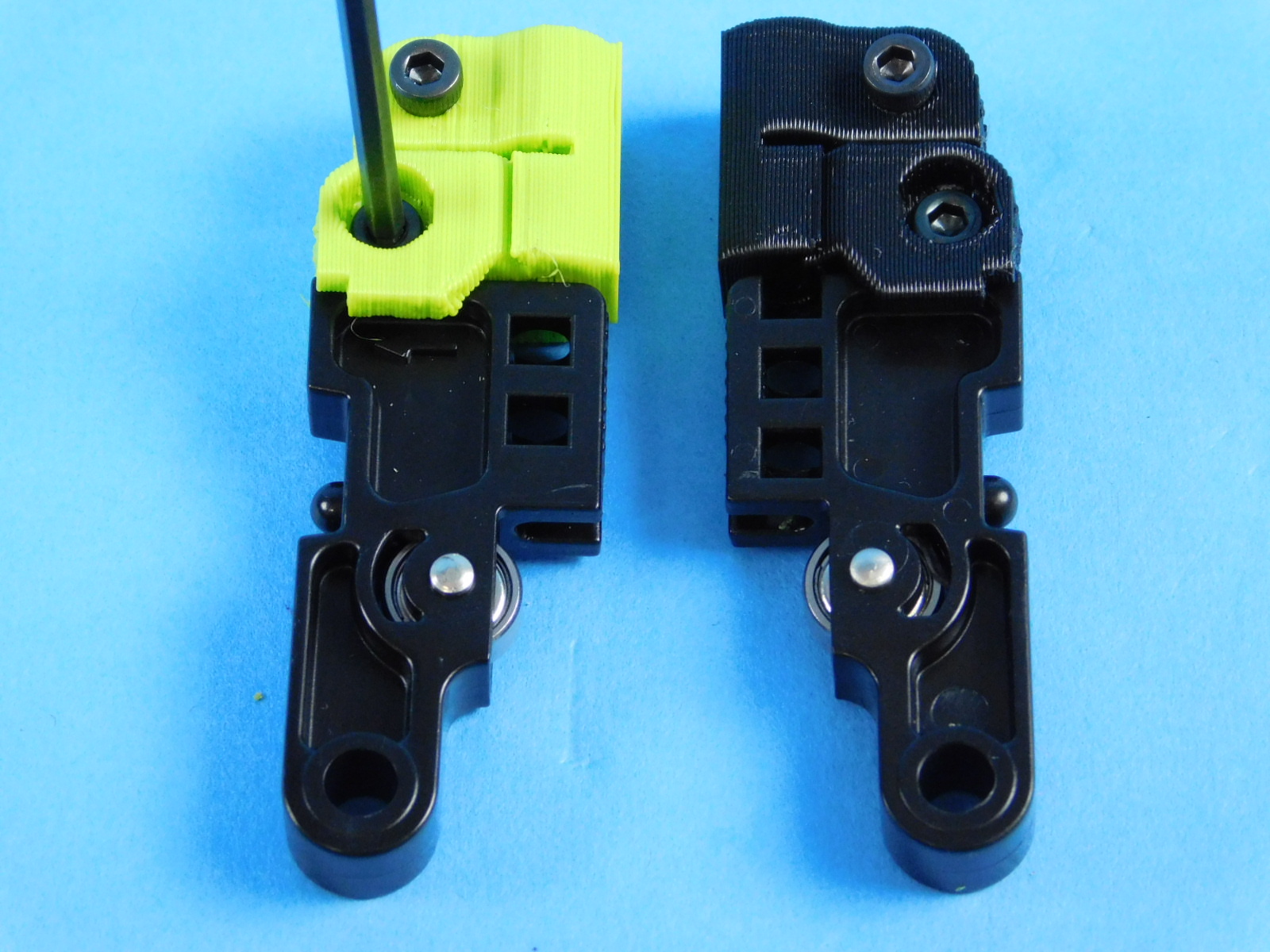
Begin by identifying the standard and mirrored idler levers and attach the idler clamps to their correct part, fasten with the four HD-BT0157. The pin for the bearing in this part can help with identification.
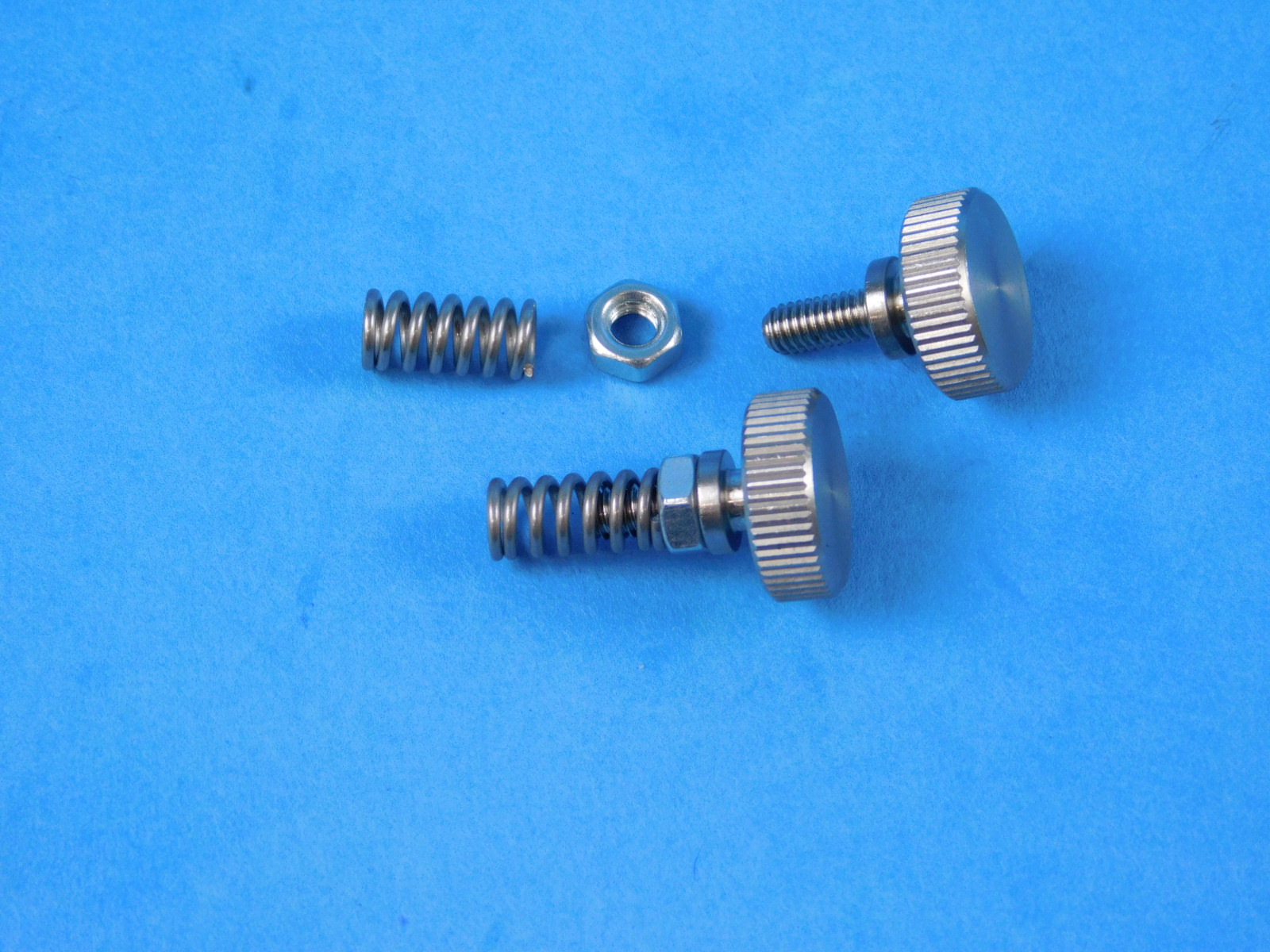
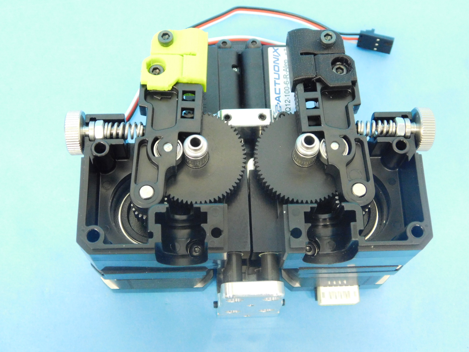
Assemble the thumbscrew tension springs by screwing the HD-NT0011 m4 nut to the base of HD-BT0197, finish by placing the HD-MS0430 spring over the end of the threads.
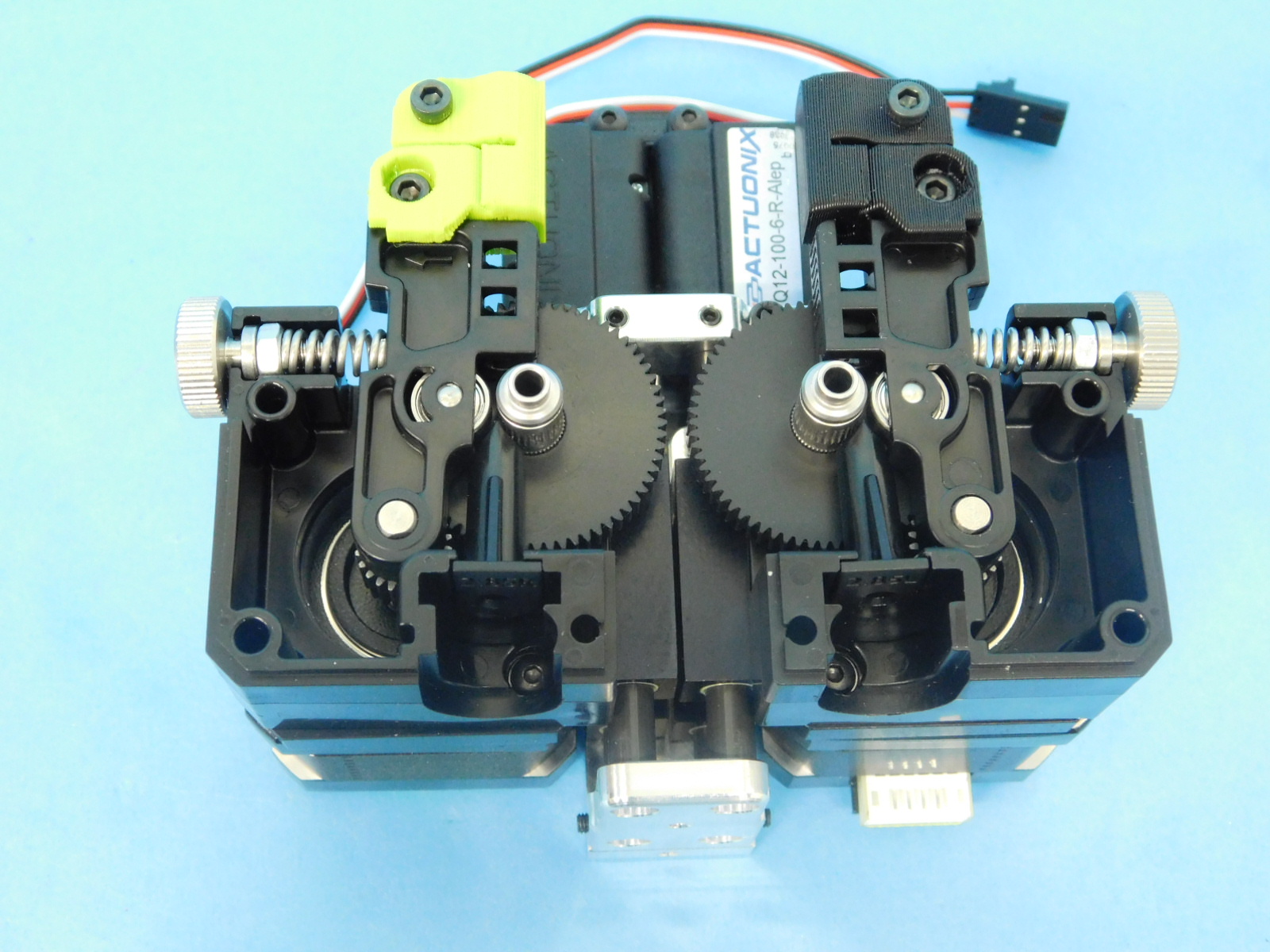
Install the two PP-FP0154 extruder hobb gears into the bearings and ensure the teeth are flush with the pinion gear
Place the two idler lever assemblies over the motor shaft of each motor, ensure the idler bearing is facing towards the hobb.
Place thumbscrew assemblies into the cavities of the extruder body, the end of the spring should fit over the nub on the idler lever.
Put each filament guides into the cavity below the hobb, they should only fit on their appropriate cavity but verify with the markings on the bottom of these parts.
Place each harness onto the assembly, make sure the hobb shaft and filament guide are not out of alignment.
Install four HD-BT043 into the top row of holes of the front plate, capturing the o-ring terminated cable on the upper right and left positions. Install the two HD-BT041 into the lower right and left positions. Torque these to 3in lbs, starting with the HD-BT041 and ending with the HD-BT043 securing the hobb gear.
Finish by placing the fan, EL-HR0170 fan guard, and secure using eight HD-BT0204.
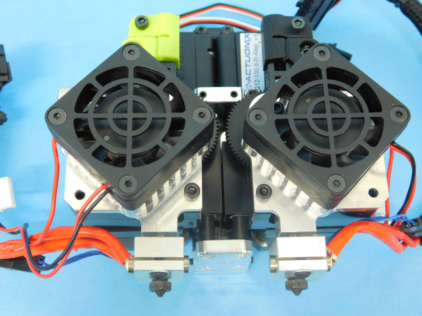
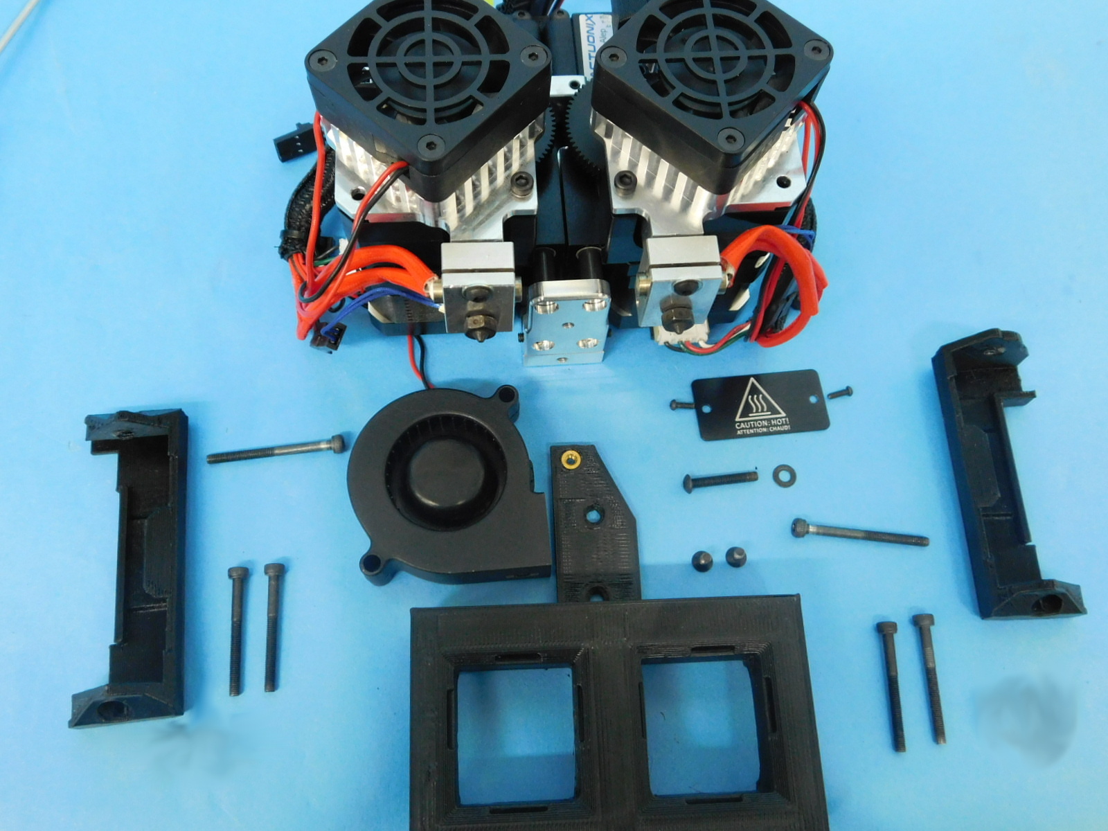
Materials:
Assembly from step 7
2x- [HD-BT0042] - M3x30 SHCS
2x- [HD-BT0043] - M3x35 SHCS
2x- [HD-BT0128] - M3x6 FHCS
1x- [HD-BT0171] - M3x20 BHCS
2x- [HD-BT0235] - M2x0.4 BHCS
1x- [HD-WA0038] - M3 washer
1x- [PP-IS0085] - Blower shroud
1x [PP-GP0470] – Cable Channel Left
1x- [PP-GP0471] - Cable Channel Right
1x- [DC-LB0175] - Caution Hot tag
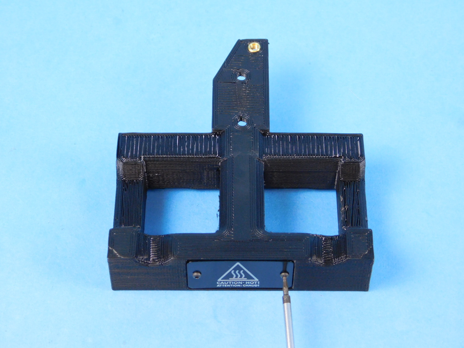
Install DC-LB0175 caution hot tag, onto PP-IS0085 blower shroud using two HD-BT0235. The top of the triangle should point towards the bed surface of the printed part.
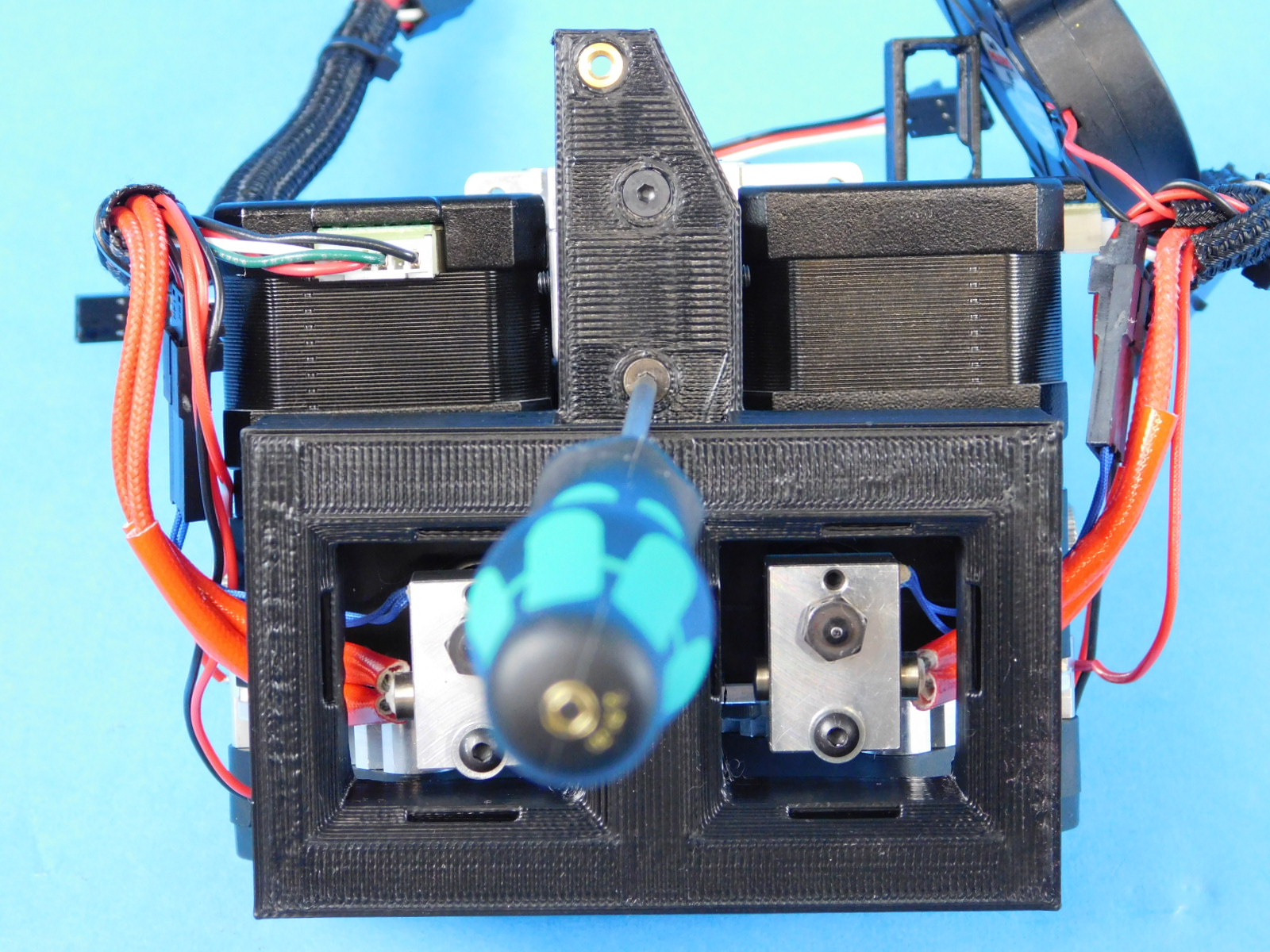
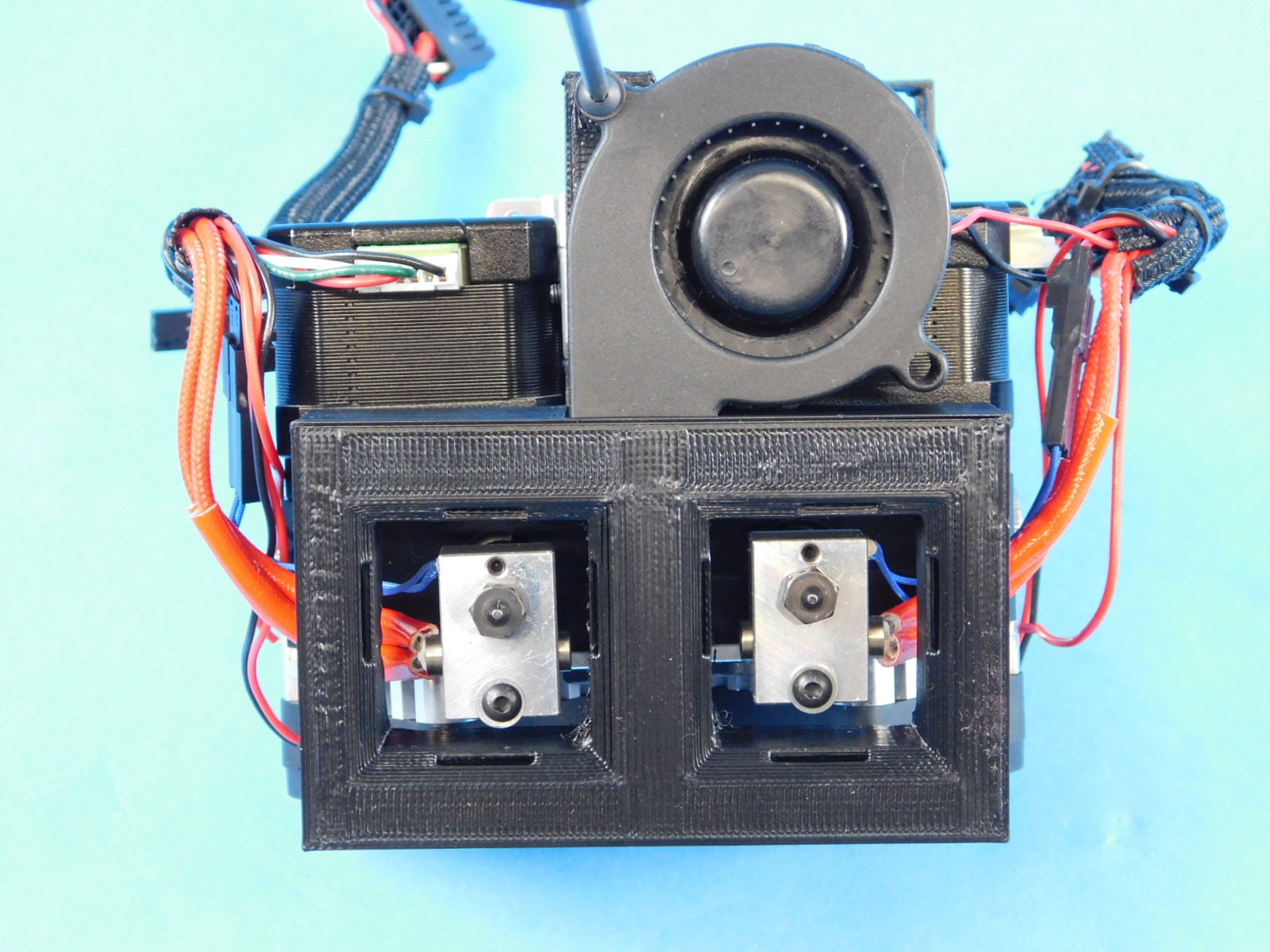
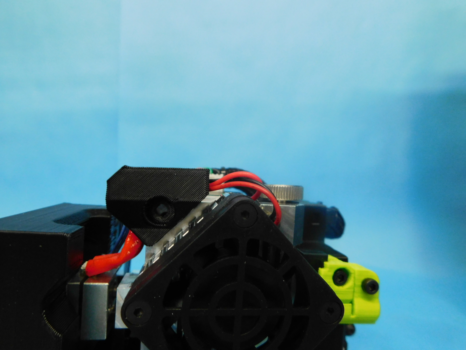
Fasten the assembled blower shroud to the bottom of the assembly from step 7 torqued to 5in lbs.
Using the final HD-BT0171 and HD-WA0038 screw the blower into the blower shroud and torque to 3in lbs.
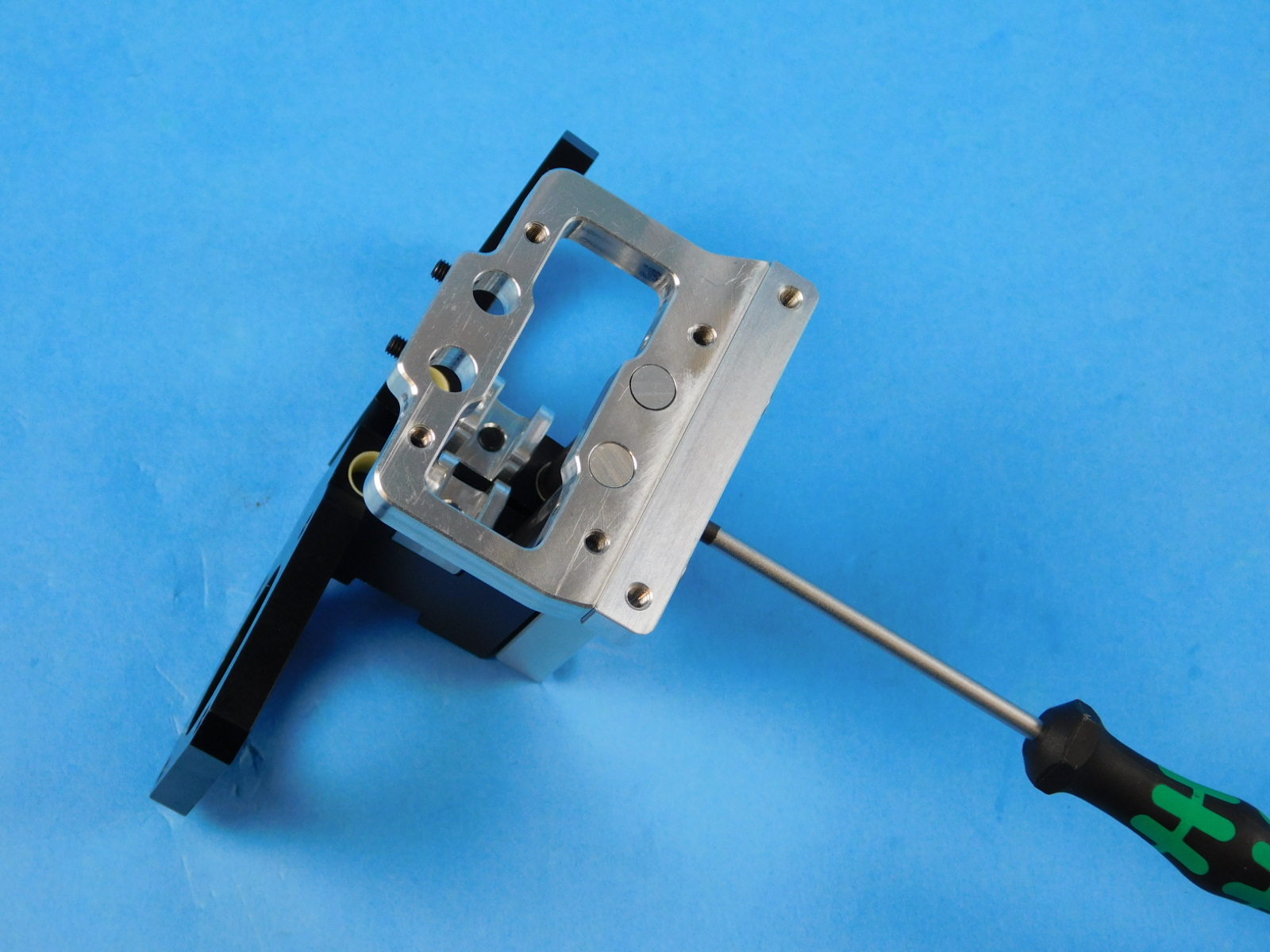
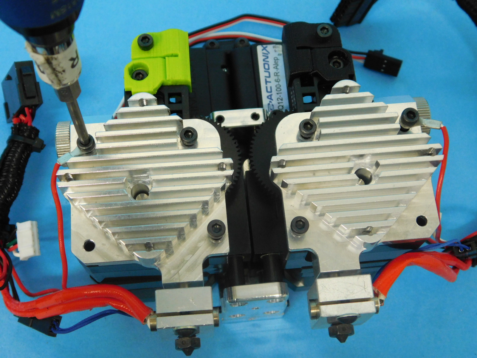
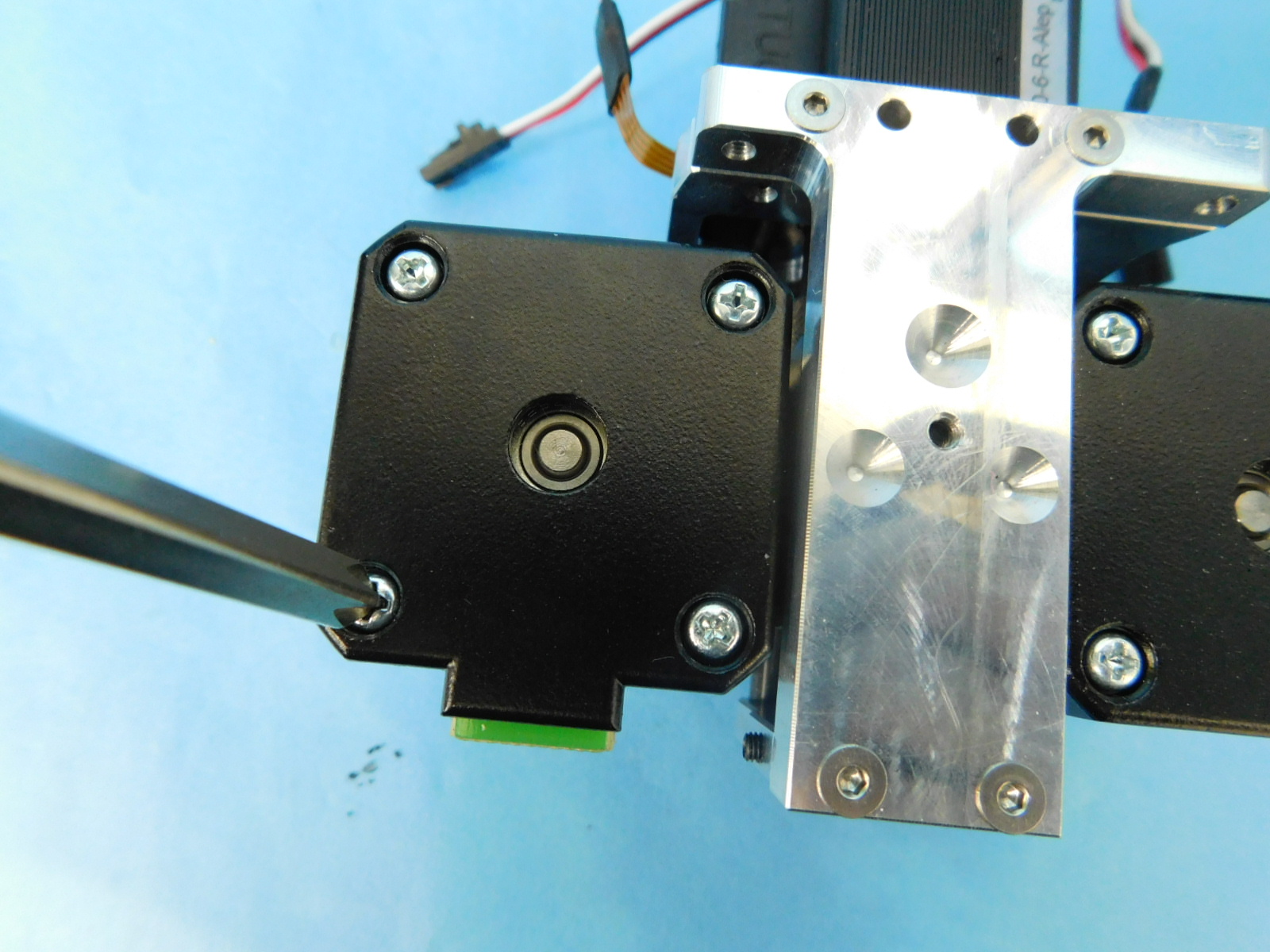
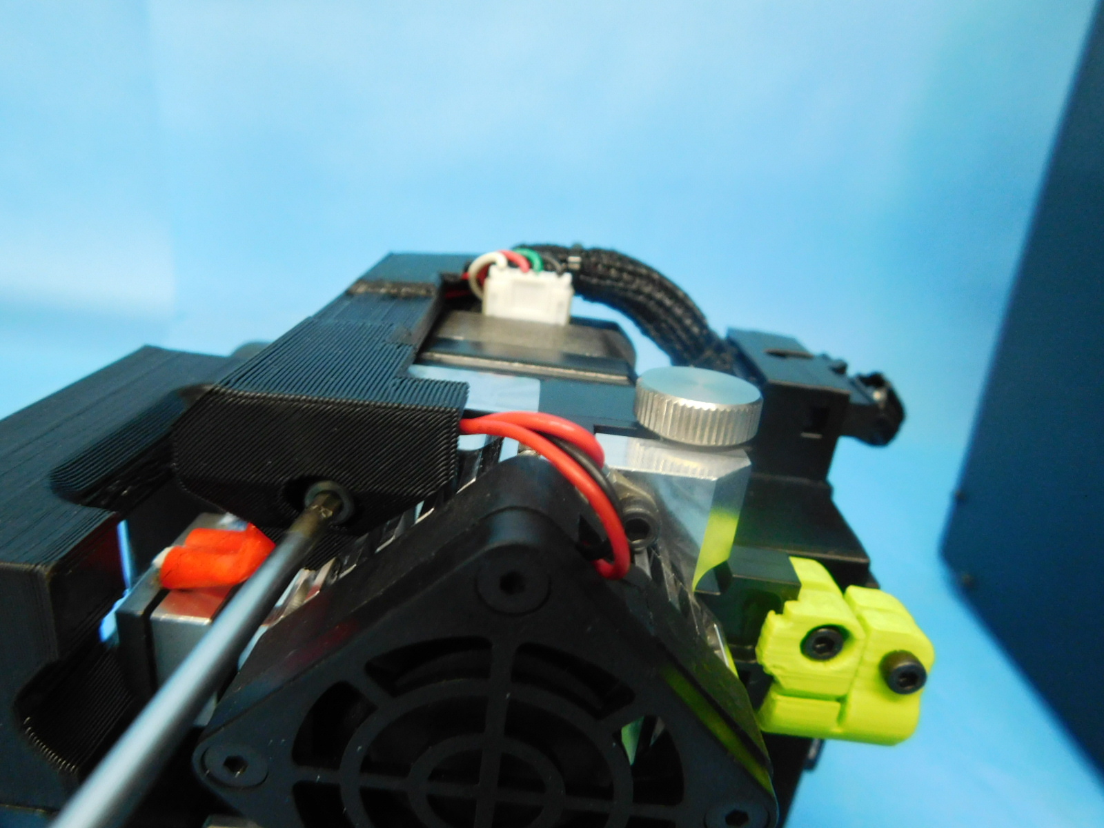
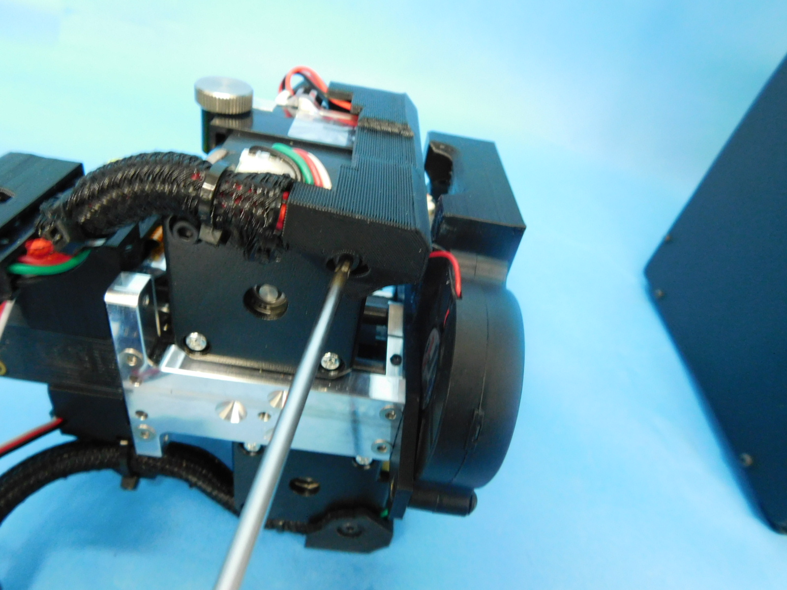
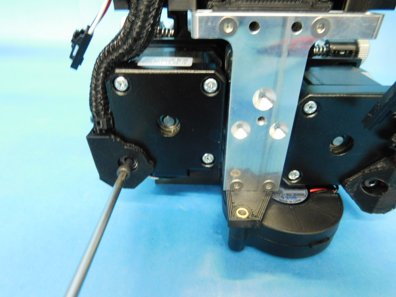
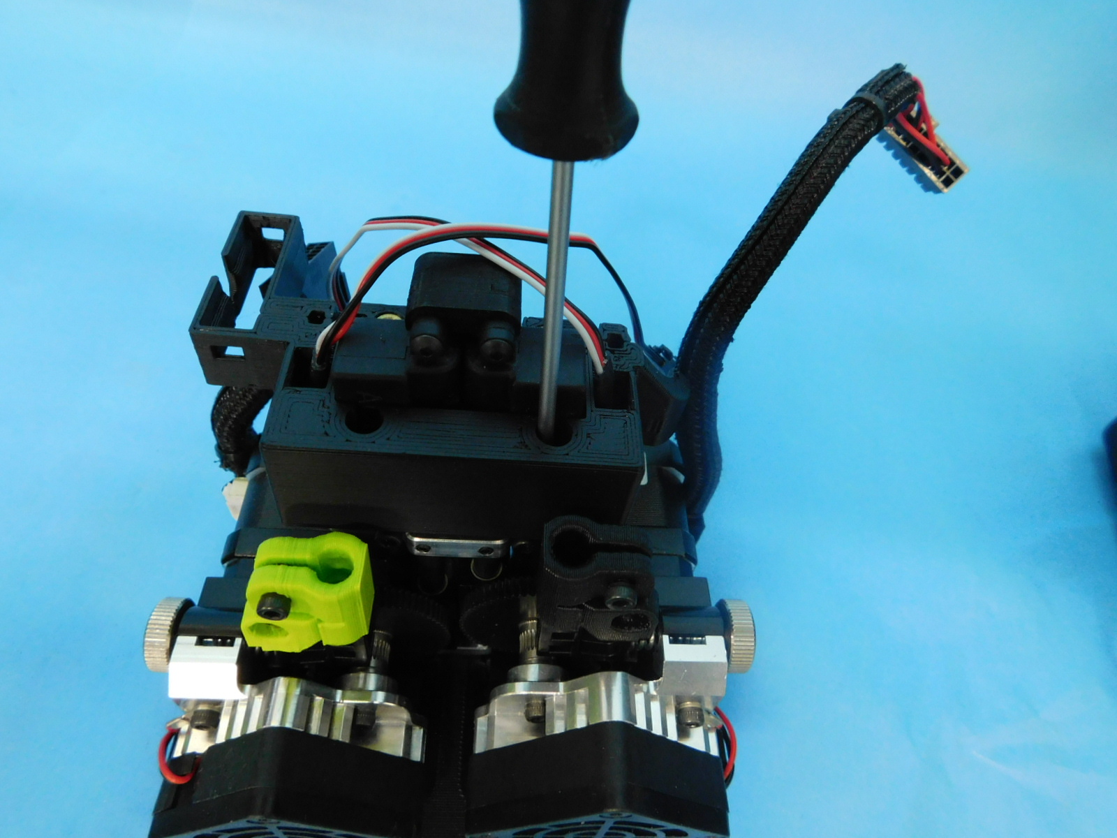
Using a Phillips head screwdriver, remove the outer bottom screw from both motors.
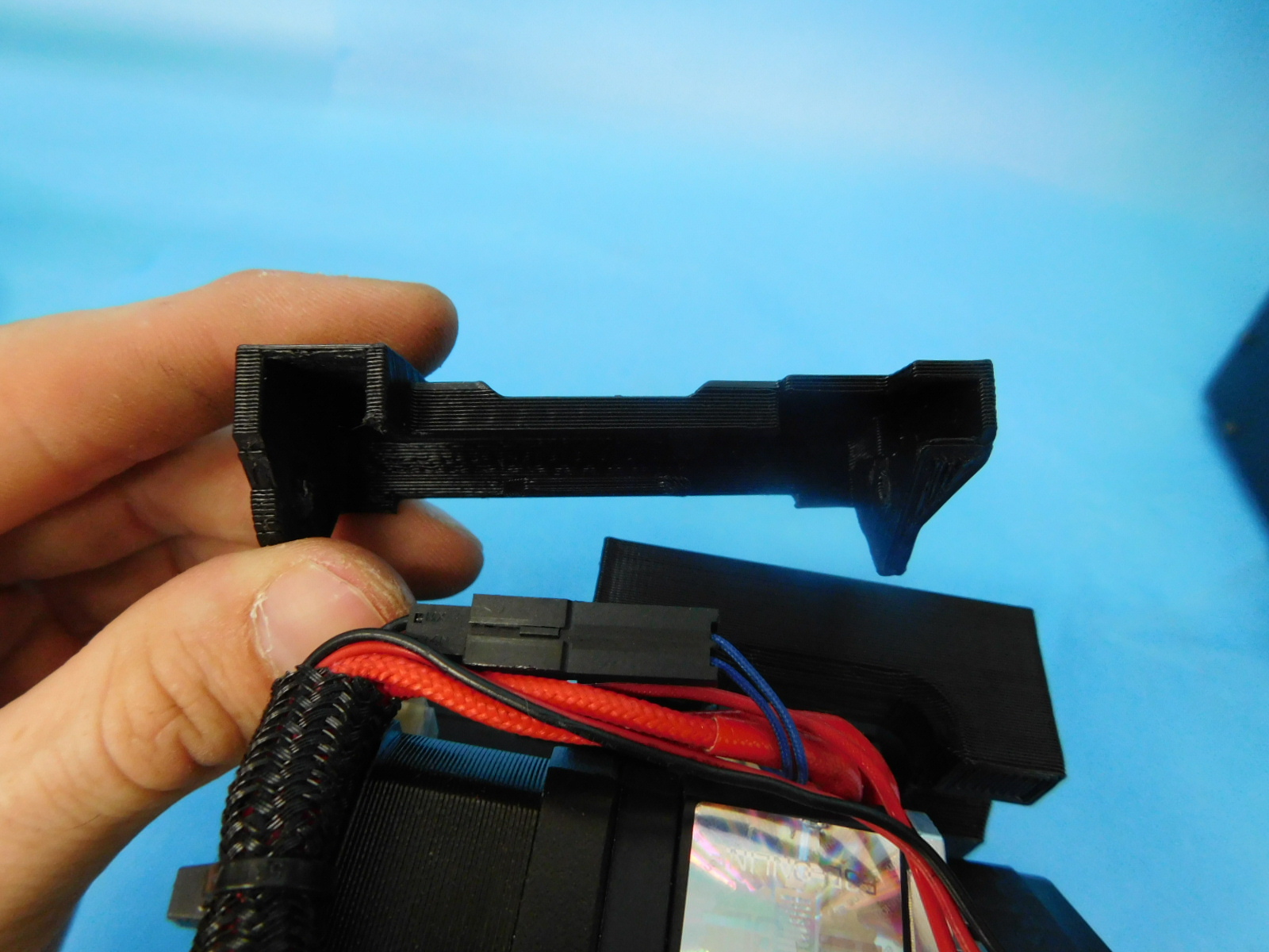
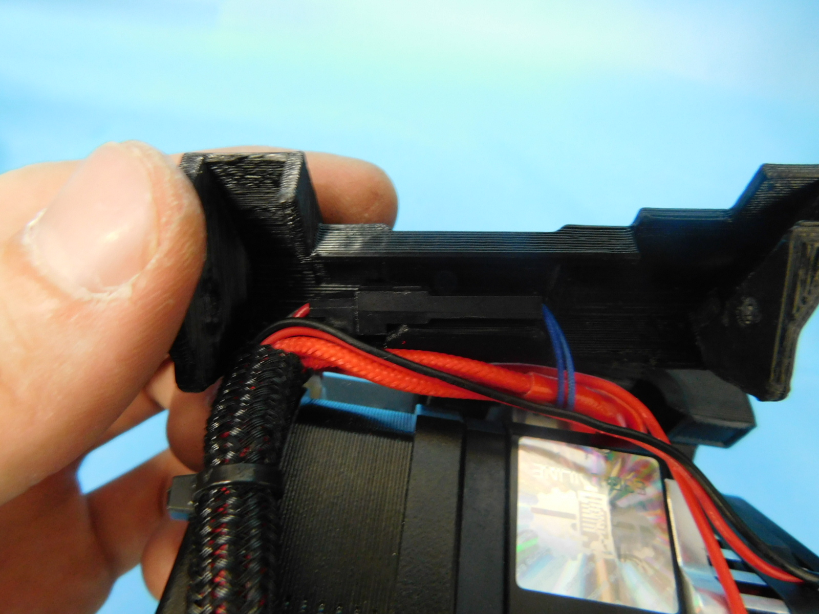
Route the cables of each harness into their cable channels by rotating the part so the divit faces outwards.. Use the final two HD-BT0042 to fasten to the back of the motors. With the tool-head facing forward, the cable channel with the larger opening should be on the right E2 side. Ensure that the channel with the larger opening is used on E2
Using the last two HD-BT0043, fasten the front of each cable channel. Do not over tighten.
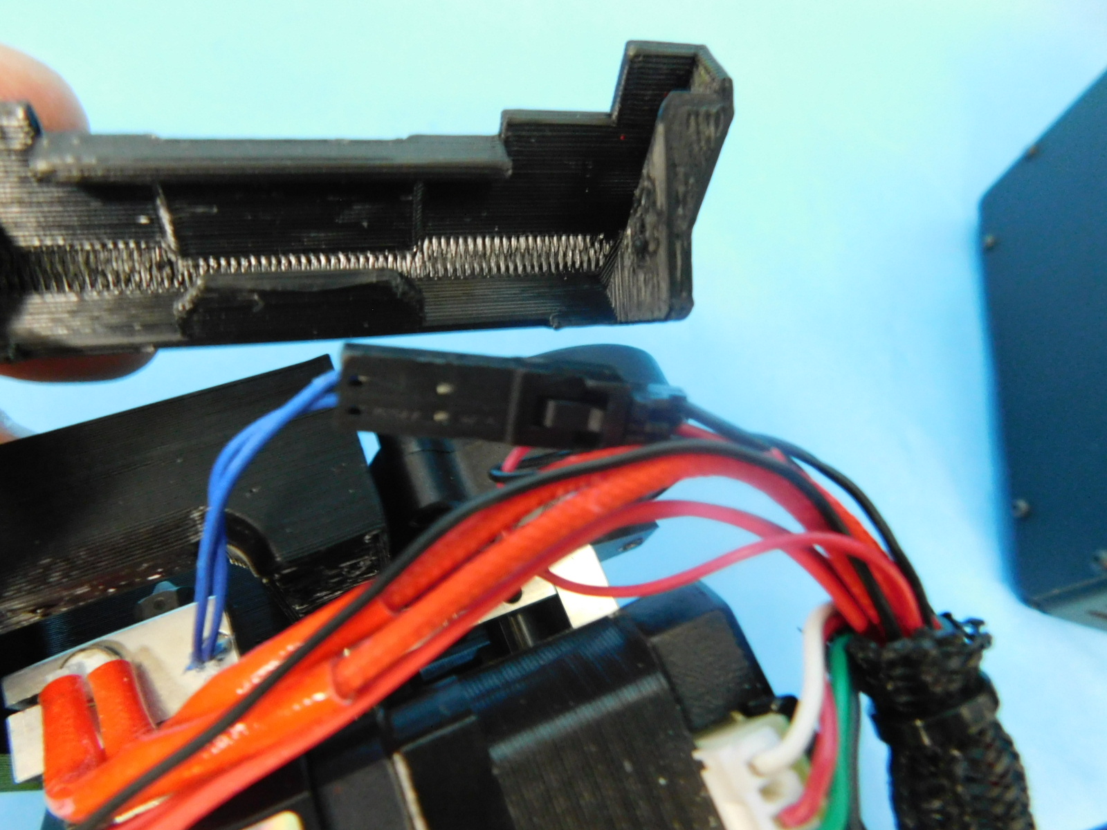
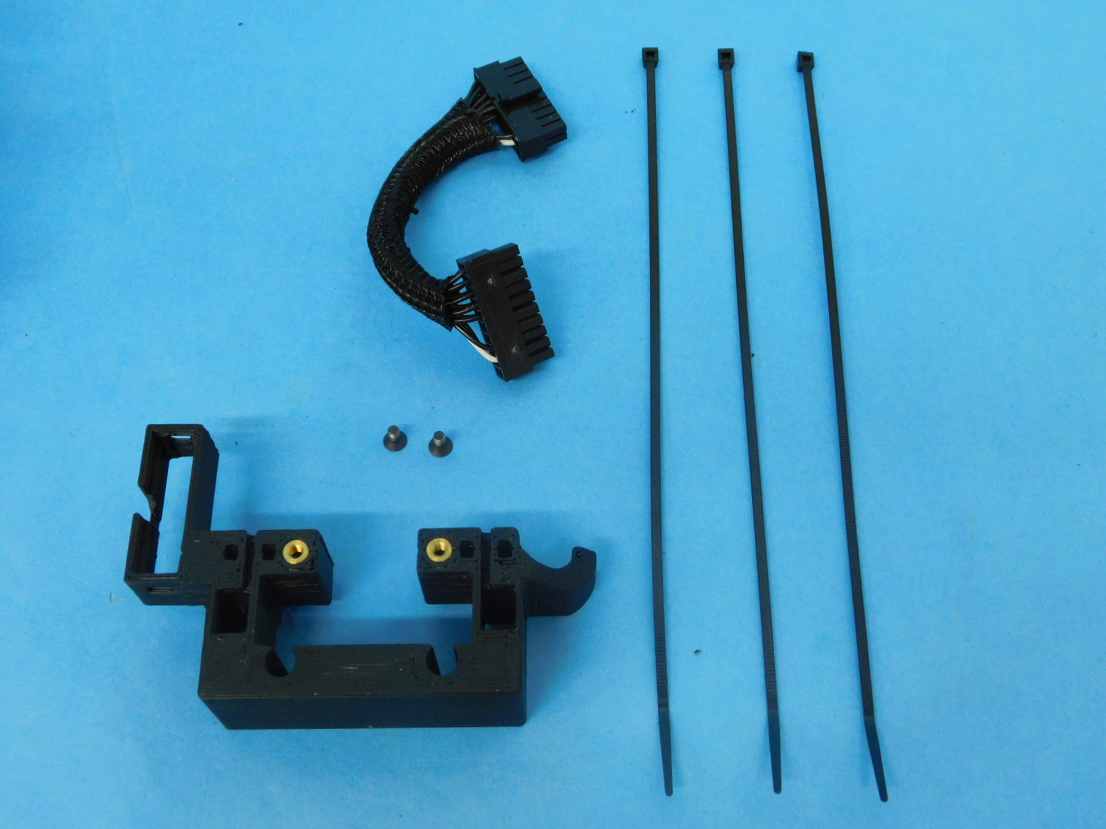
Materials: Assembly from step 8 3x- [HD-MS0058] - Ziptie 1x- [EL-HR0145] - E1 Extension harness 1x- [PP-IS0081] - Actuator cover 2x- [HD-BT0128] - M3x6 FHCS
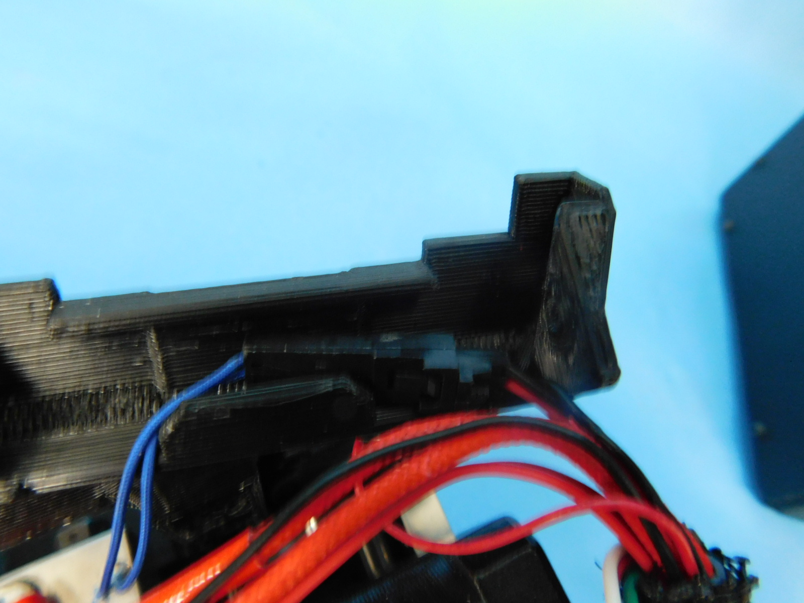
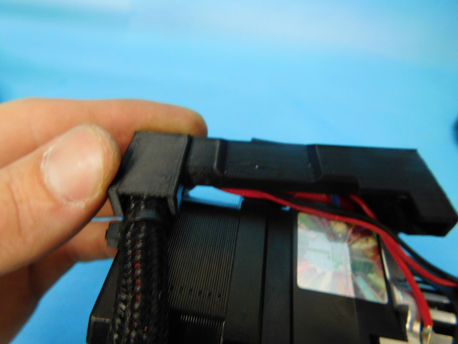
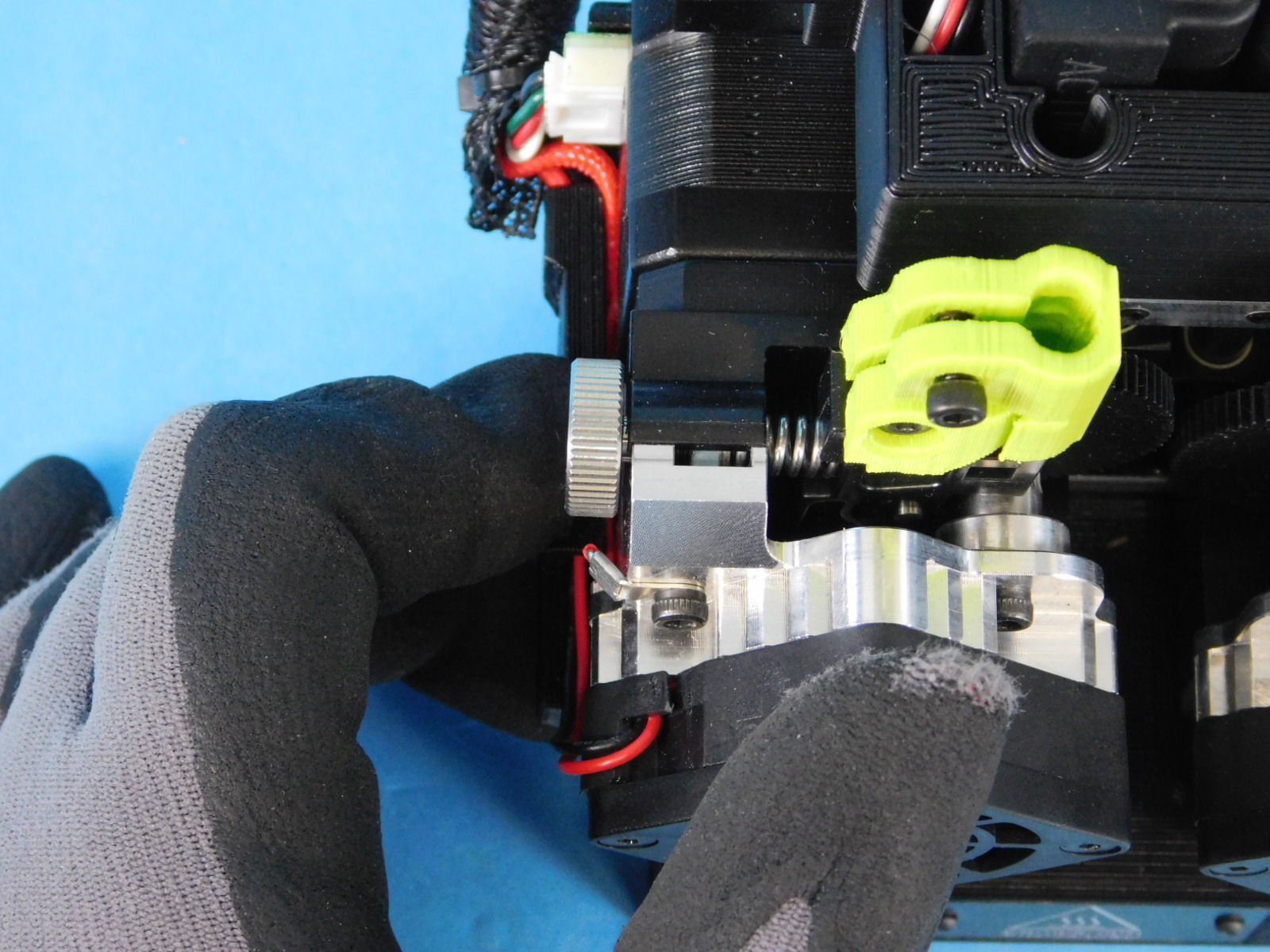
Obtain one Actuator cover[PP-IS0081] Proceed to fit the cover over the actuators, feeding the wires through the channels in the part. Be careful not to pinch the fragile ribbon cable. Fasten the actuator cover to the assembly using two [HD-BT0128] - M3x6 FHCS
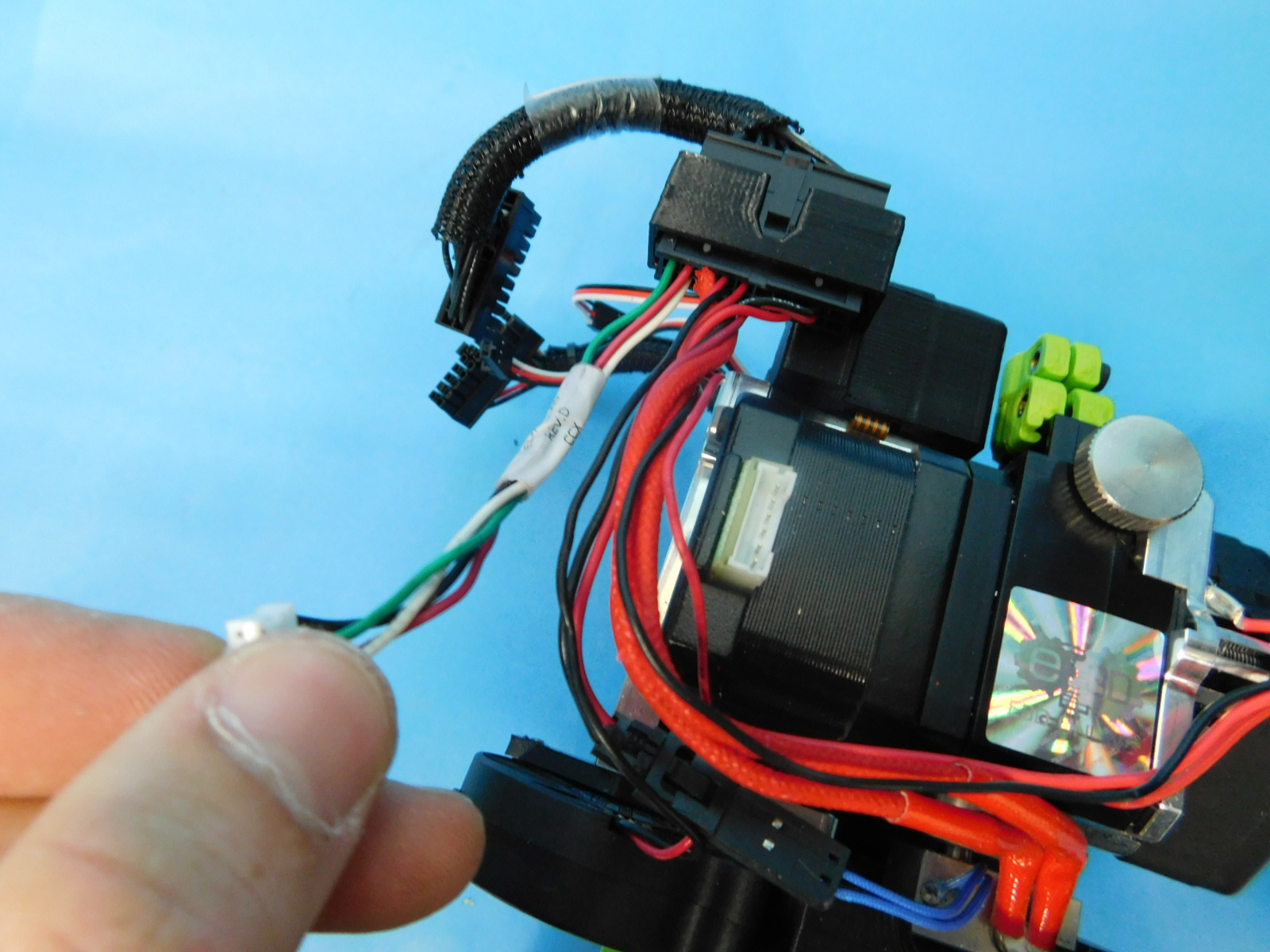
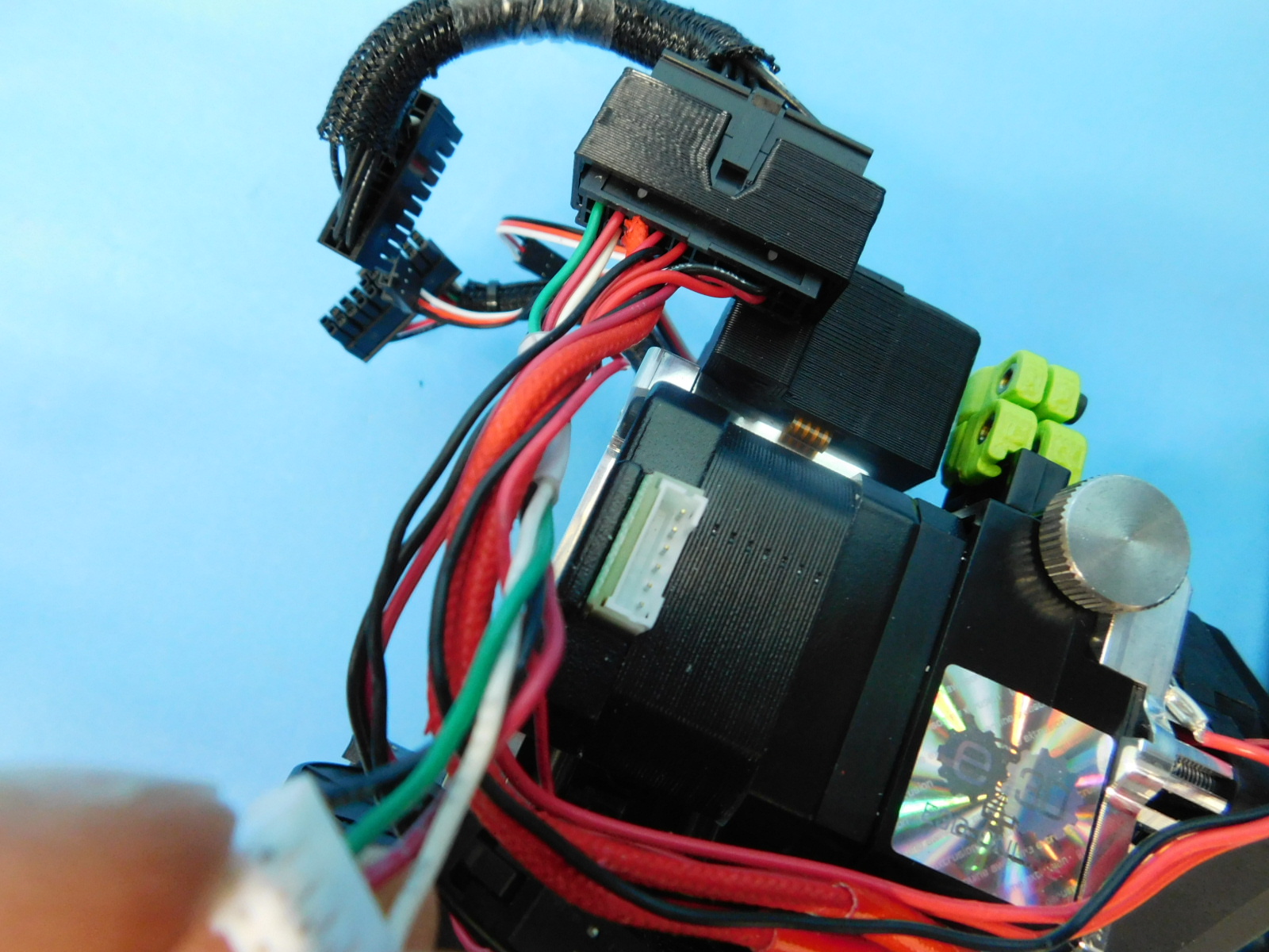
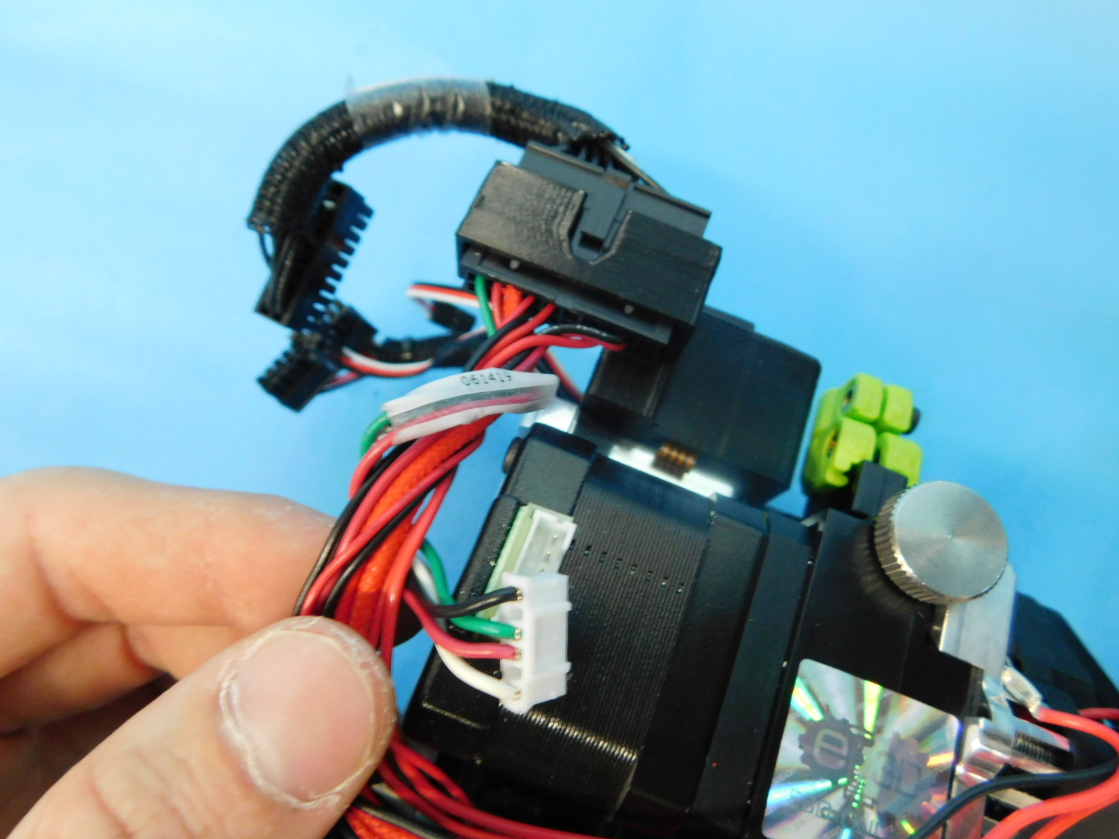
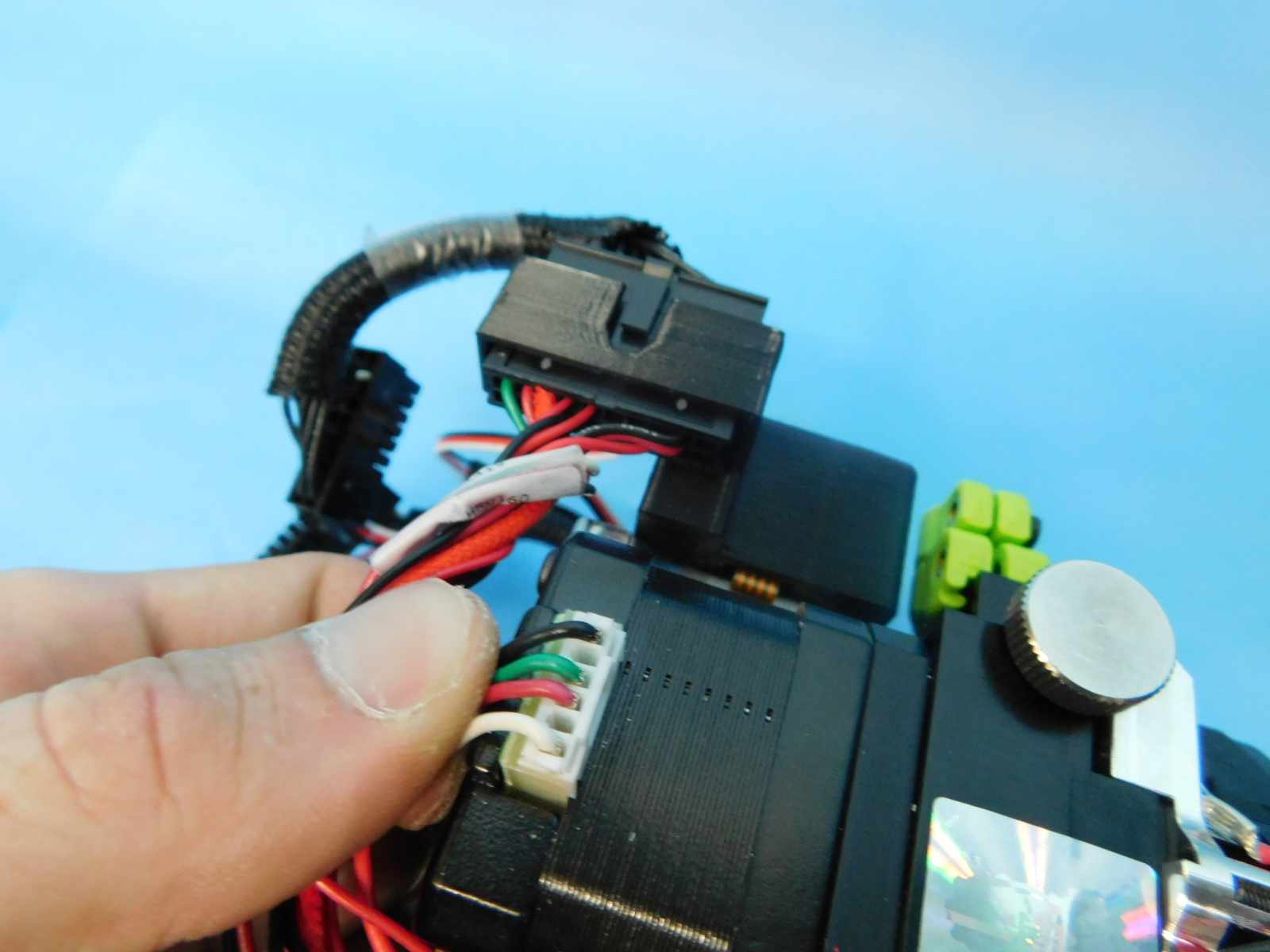
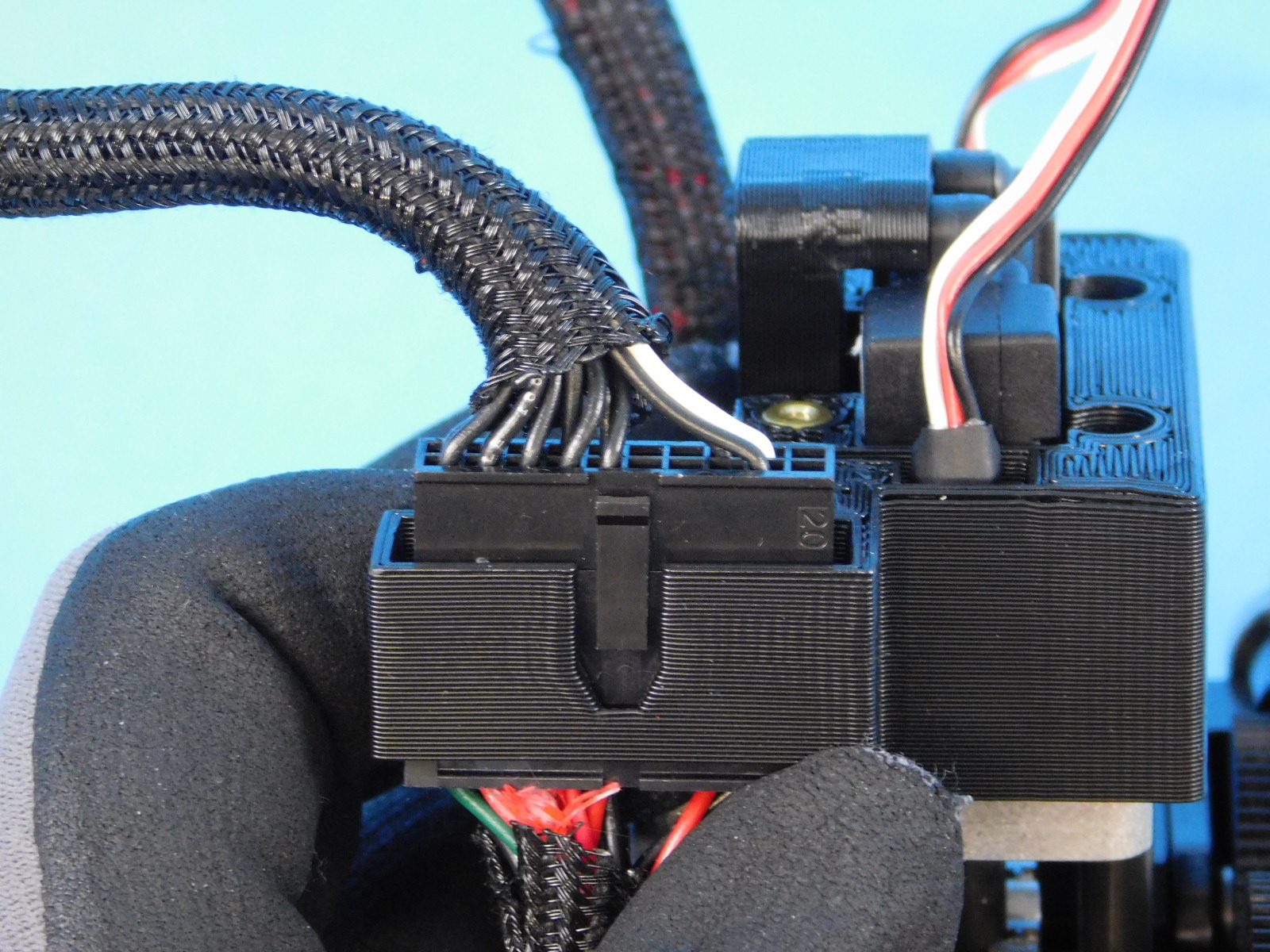
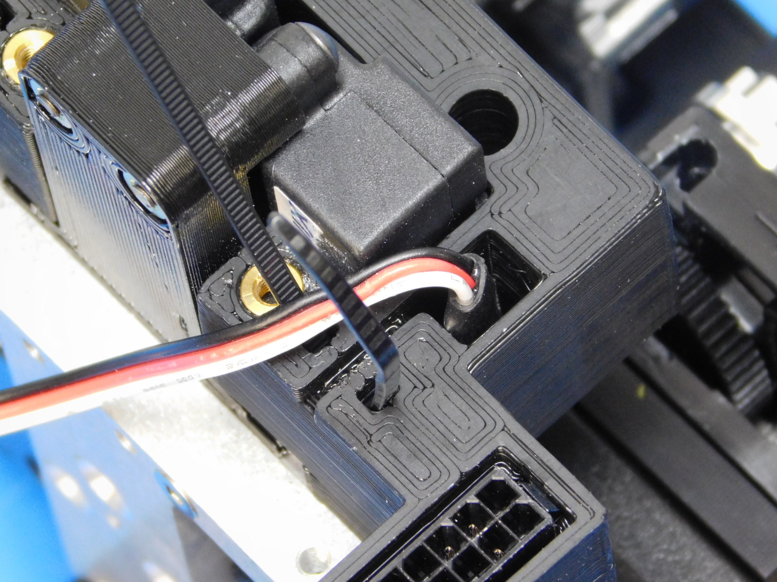
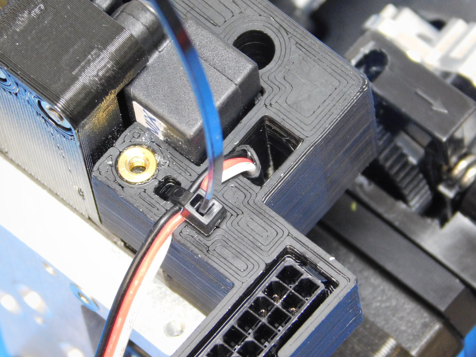
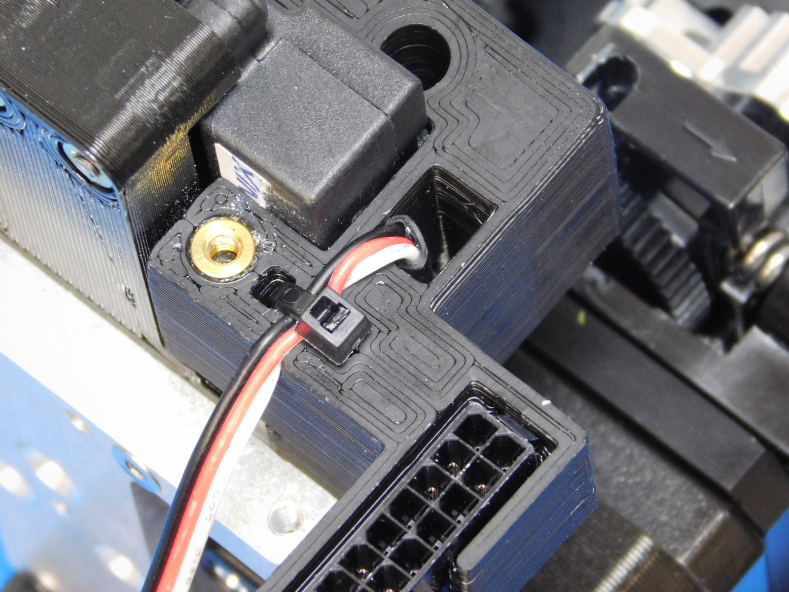
Obtain one E1 Extension Harness [EL-HR0145], and plug it into the E1 harness.
Please make a special note of the orientation of the extension cable since it is possible to plug this cable in backwards.
On the E1 plug side of the cable, there should be a lone white wire on the extension harness. This wire should be on the right hand side of the connector as shown.
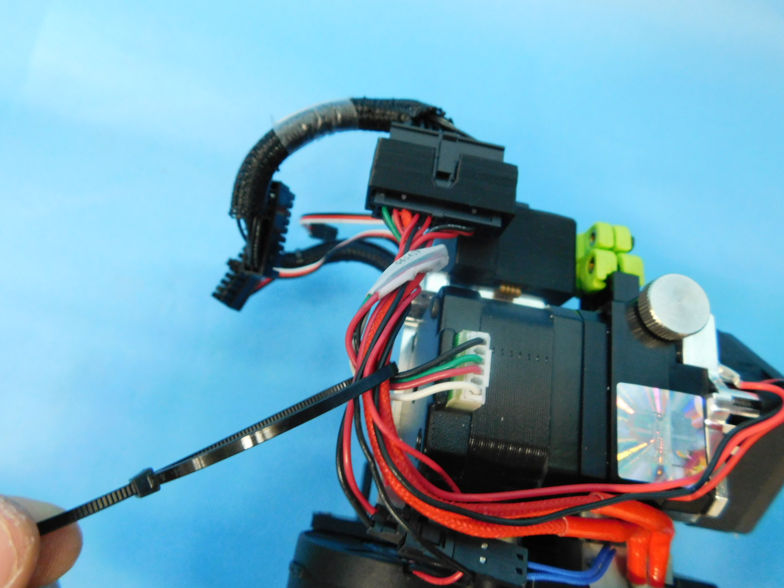
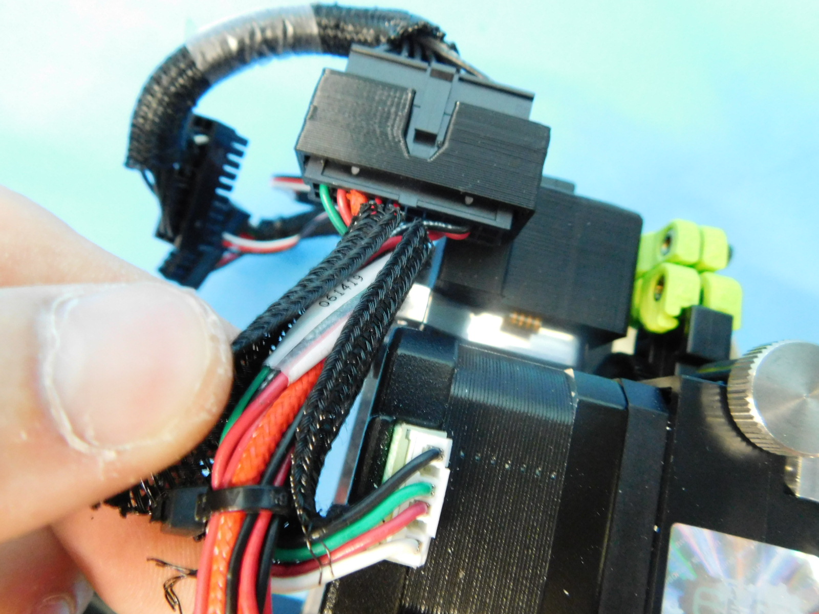
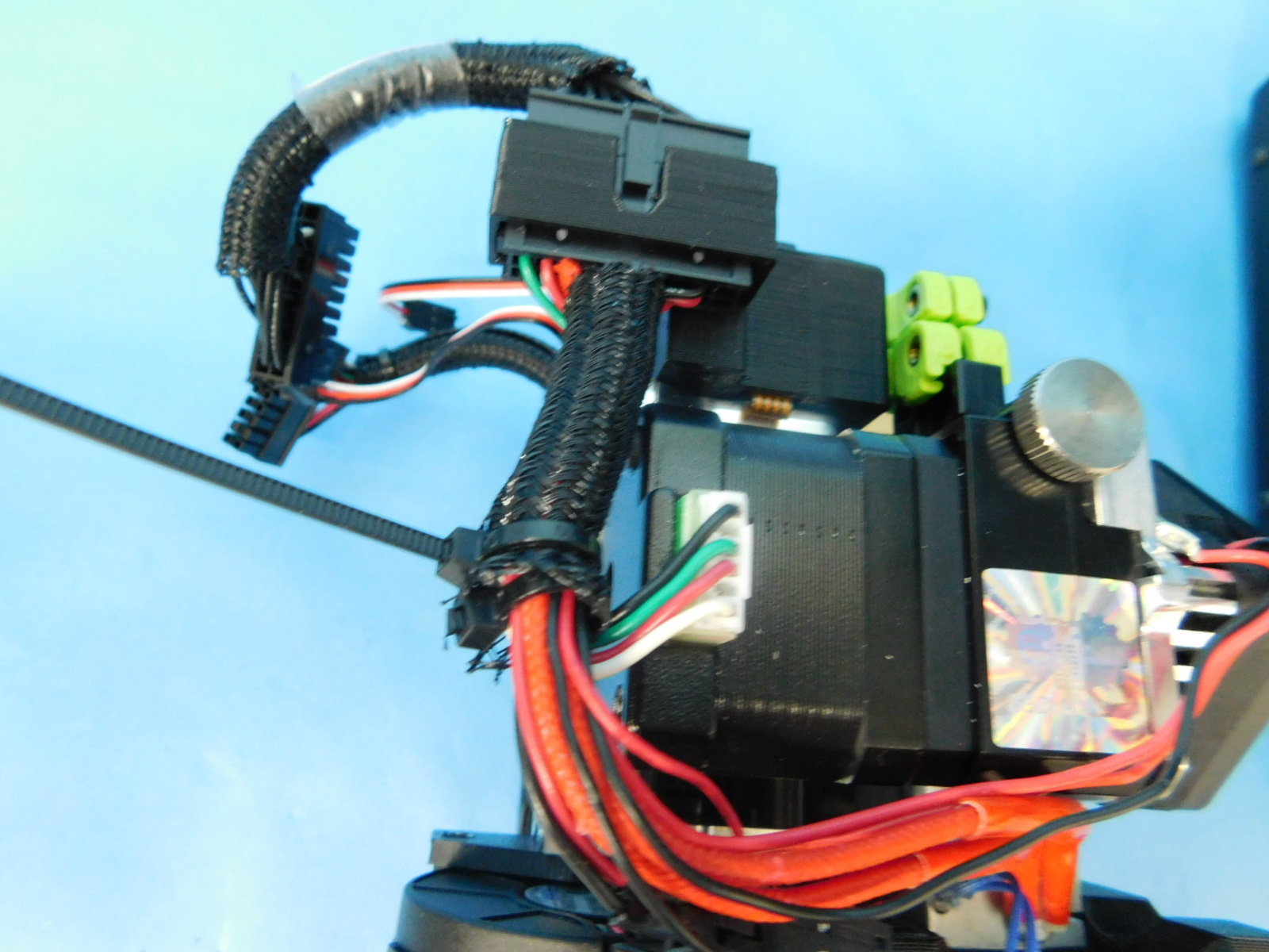
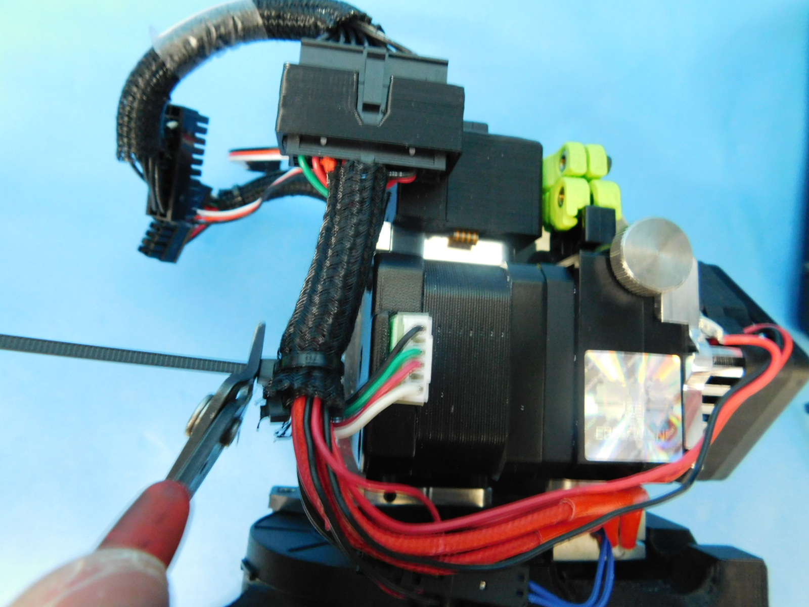
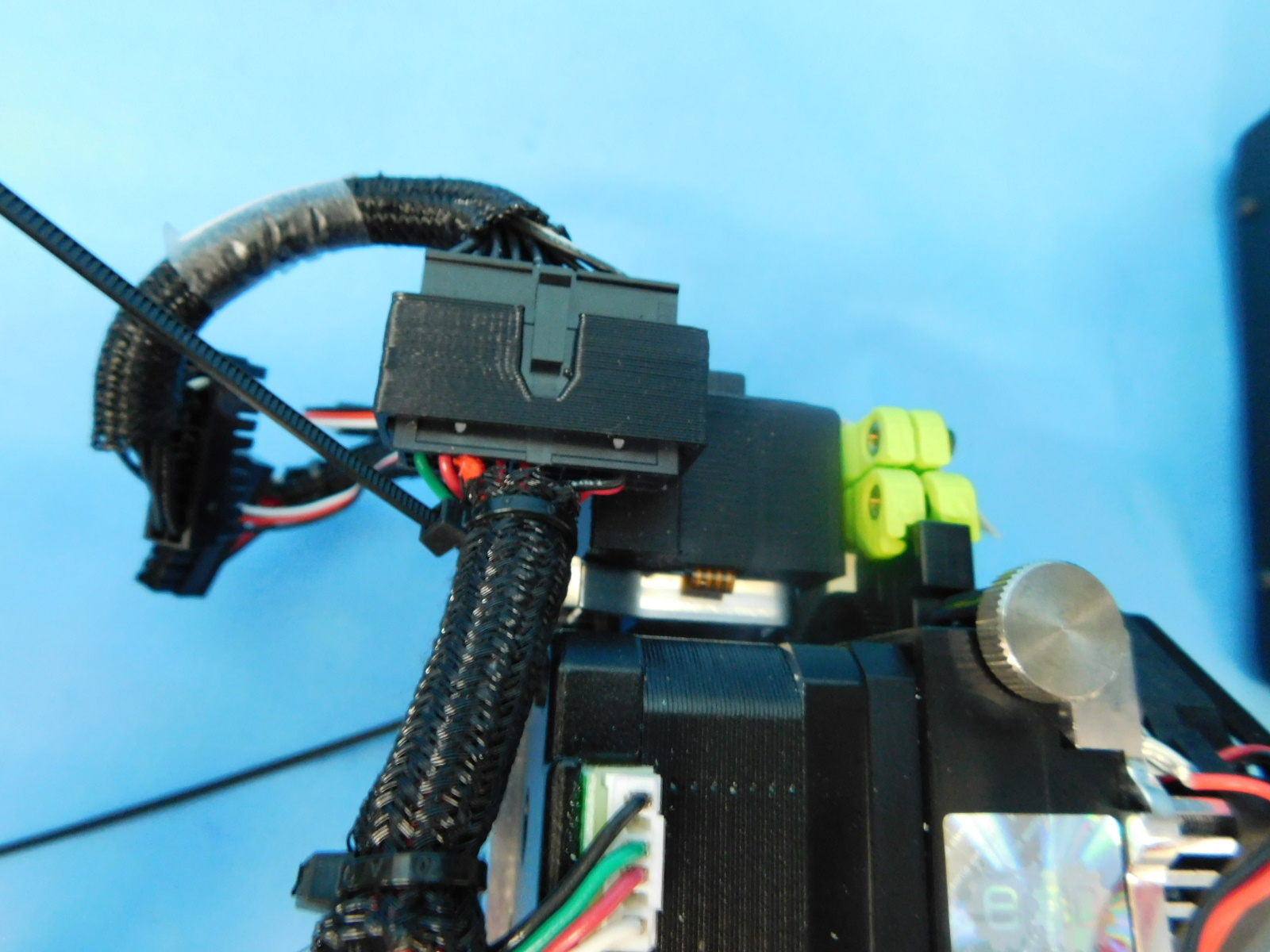
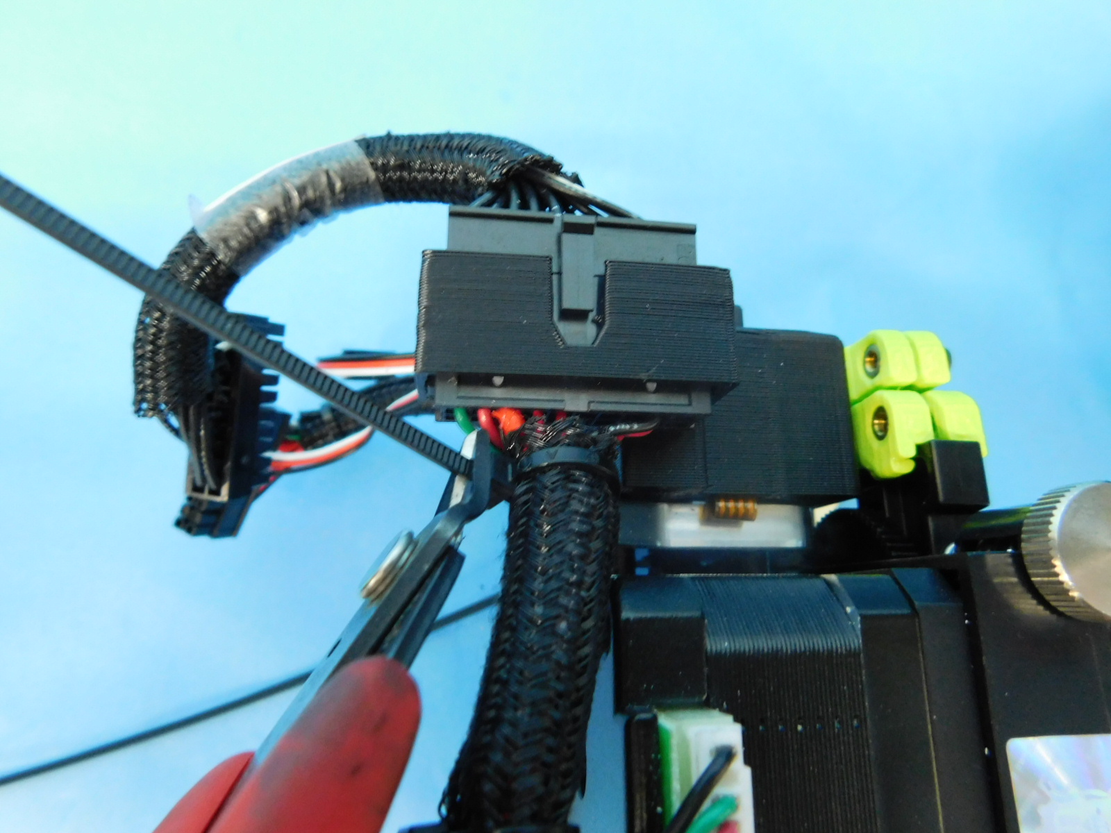
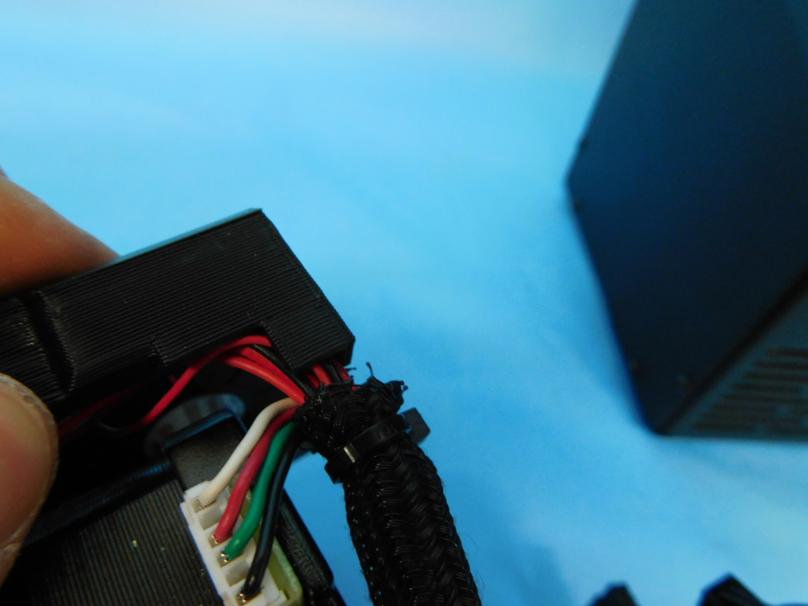
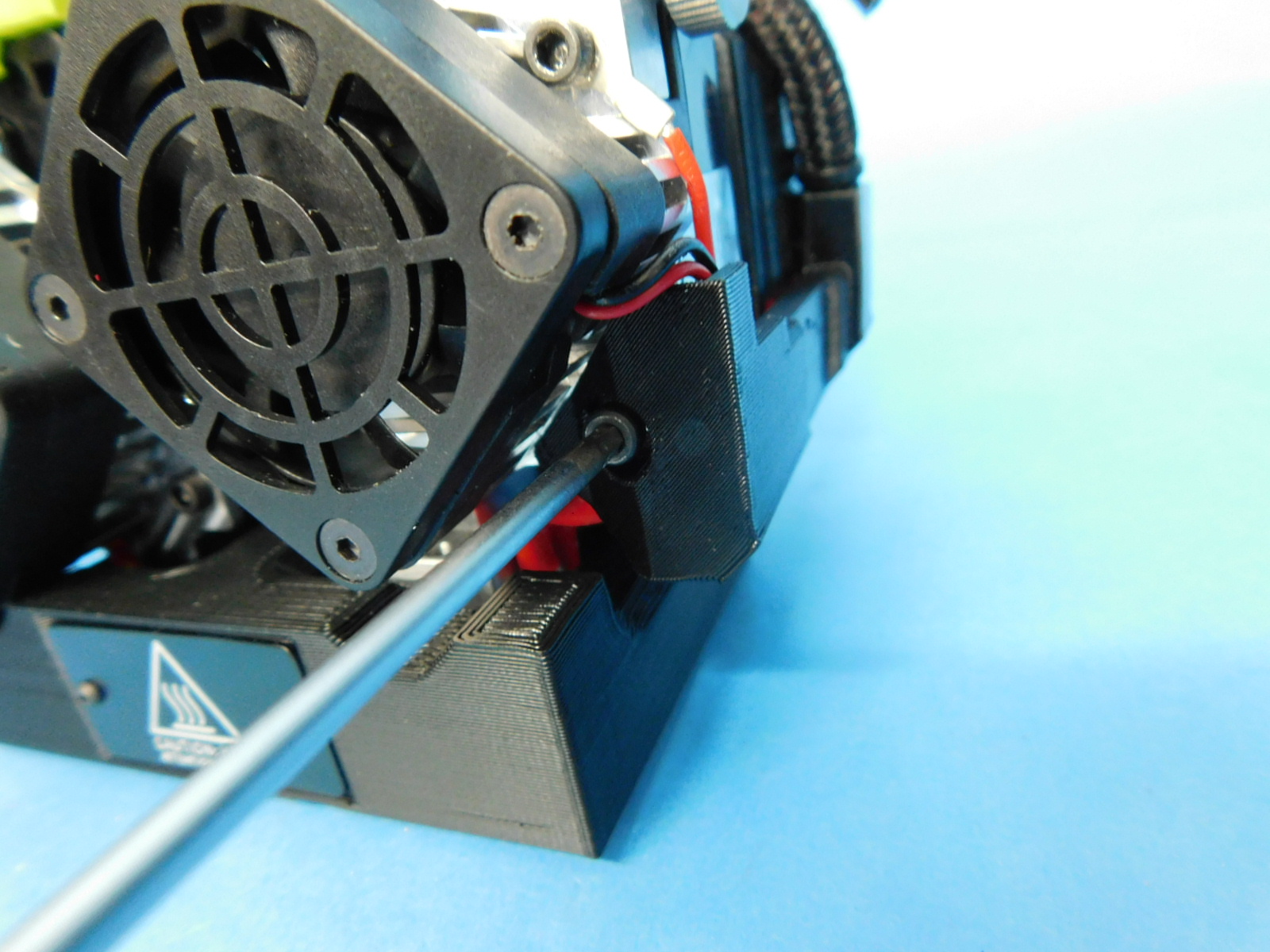
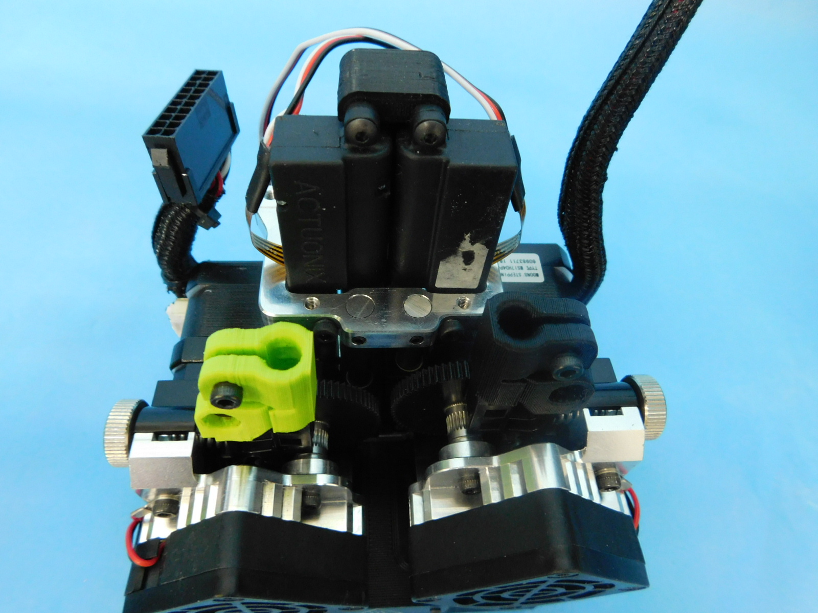
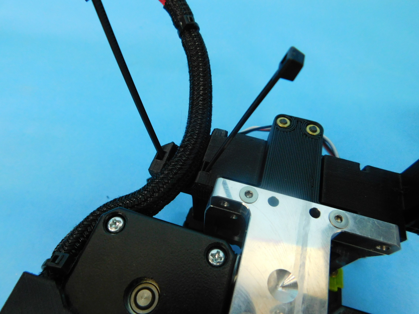
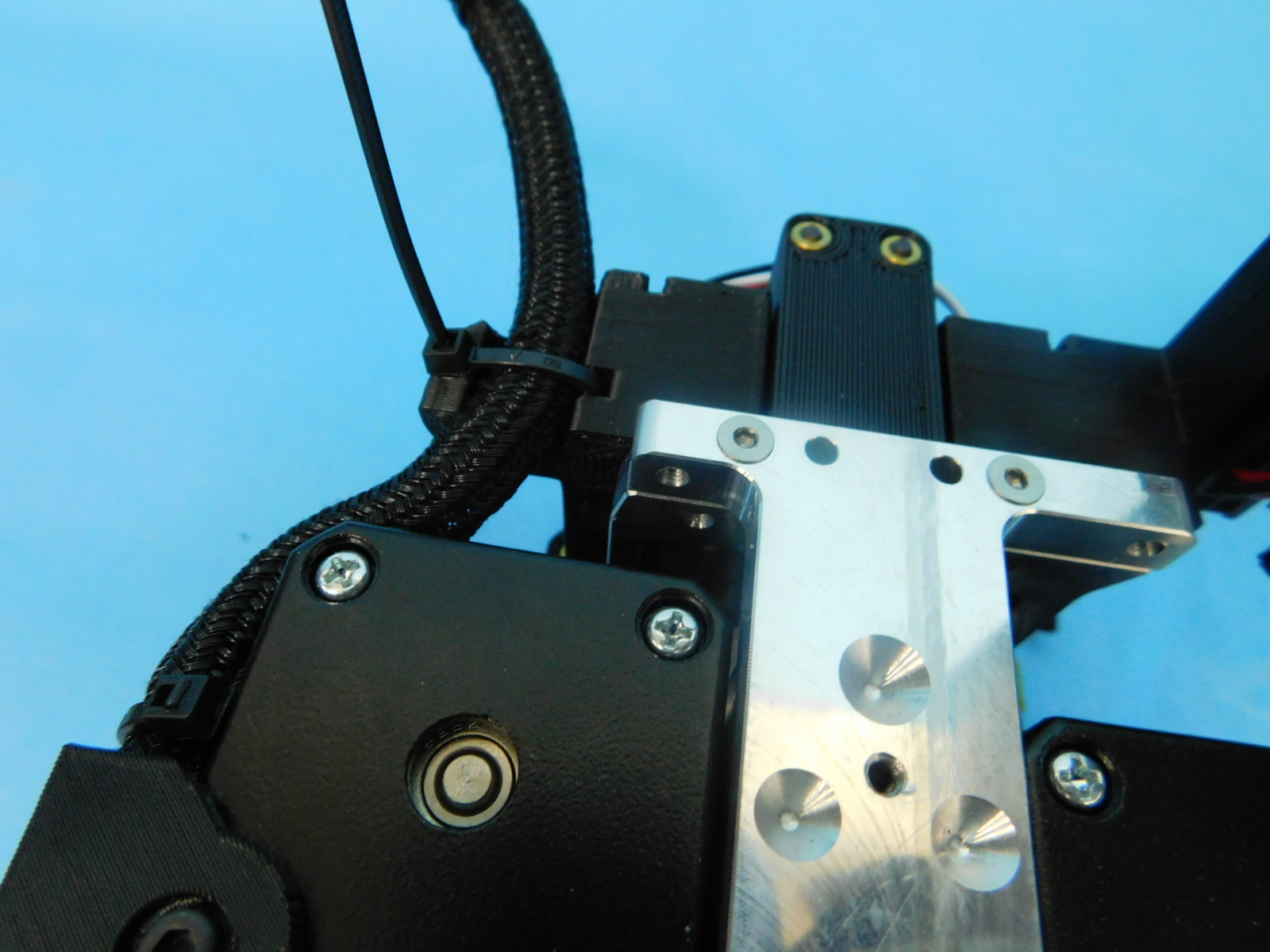
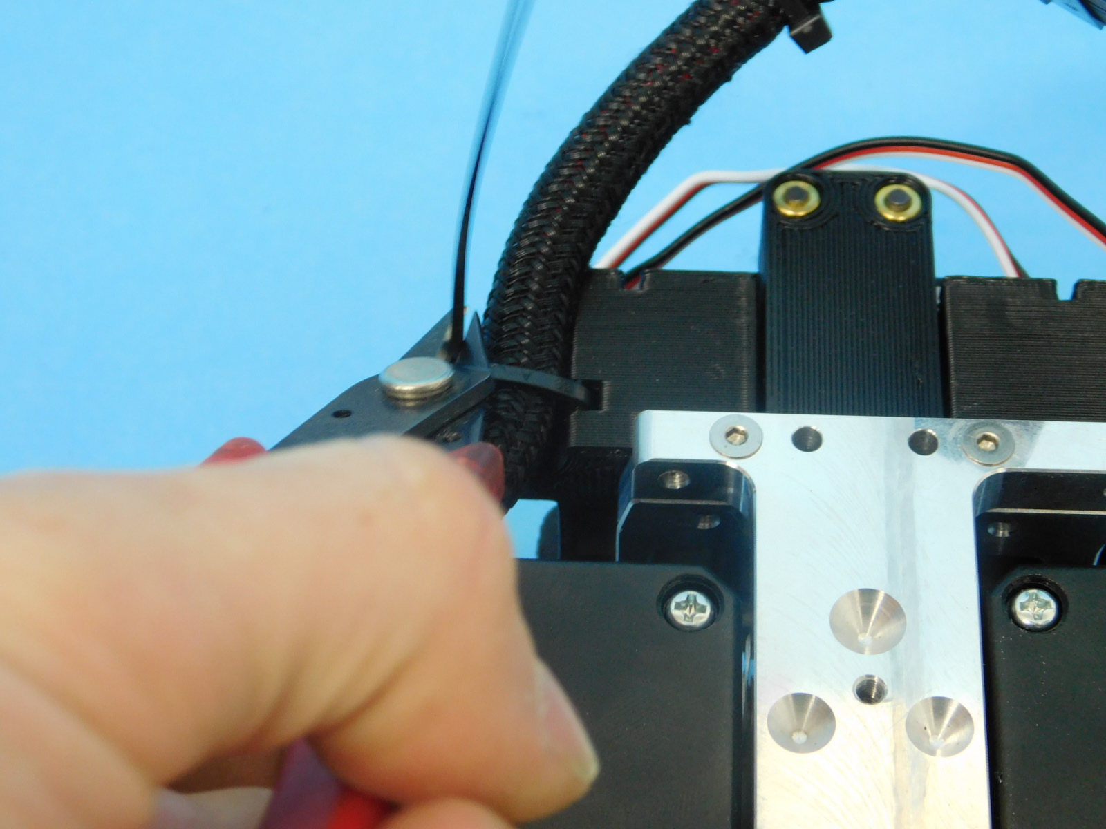
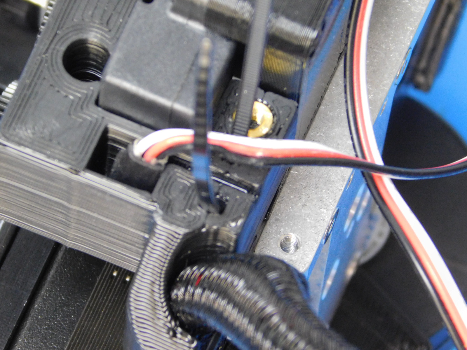
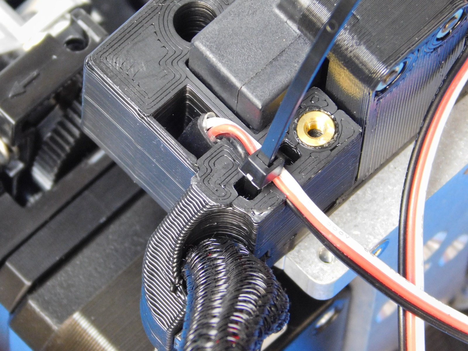
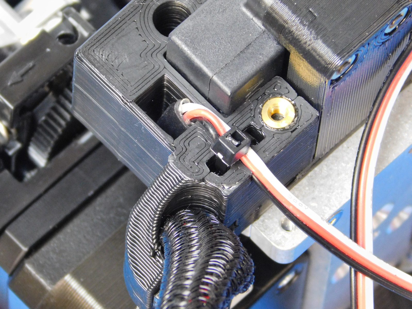
Now we will take the E2 harness and zip tie it to the actuator, you may need to bend the end of the zip tie sharply in order to feed through properly.
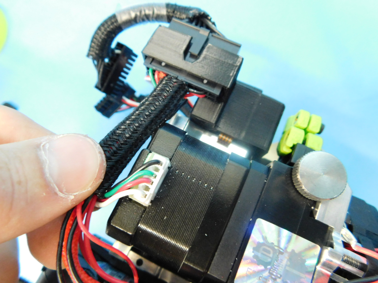
Then we will zip tie the actuator wires to the cover, do this by feeding the zip tie through the slot closest to the actuators so that the zip tie "knot" lands away from the actuators
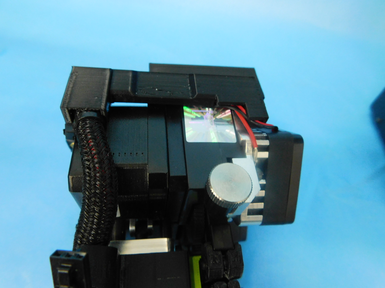
The heat shrink on the actuator wires should be about level with the top of the actuator cover.
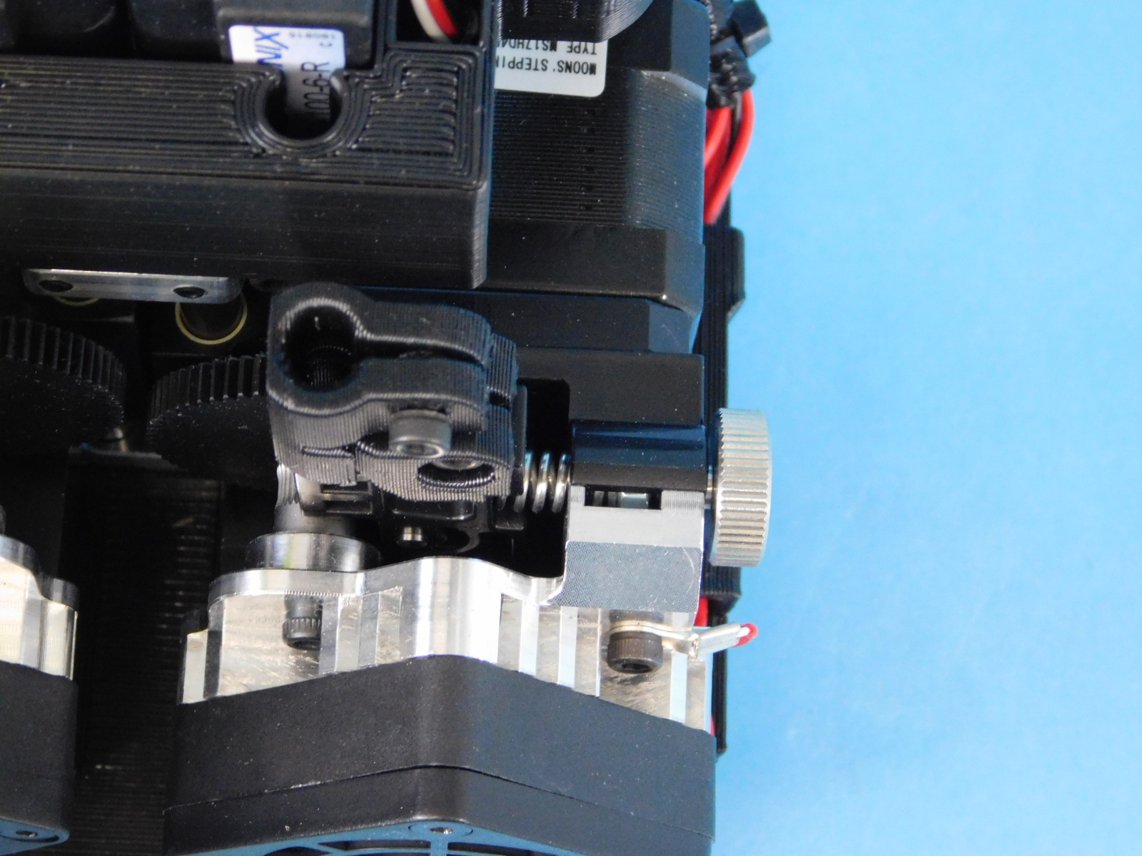
Turn the idler spring compression thumbscrew [HD-BT0197] until the idler spring compression nut is in the middle of the adjustment window.
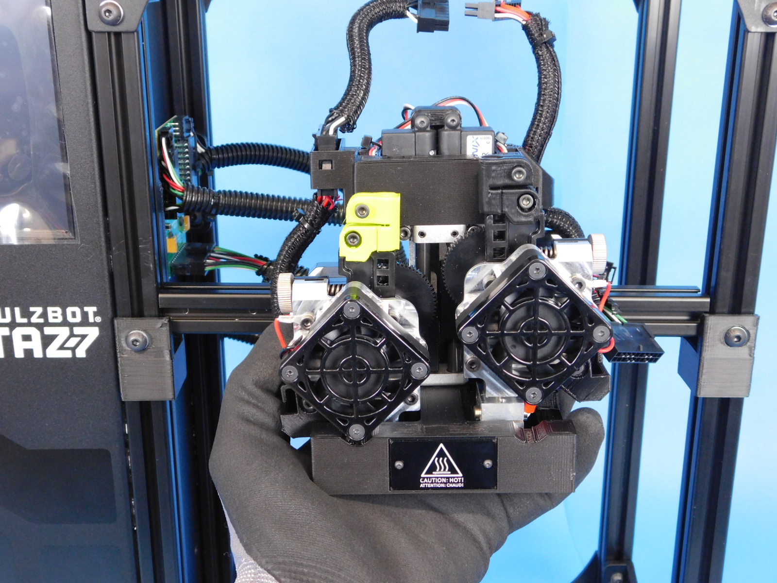
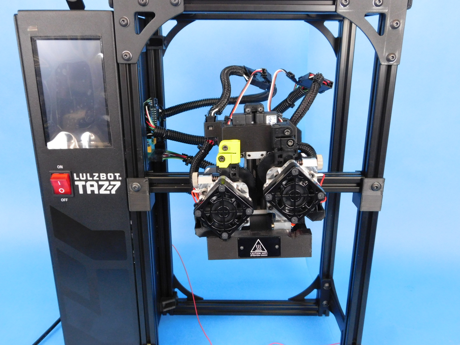
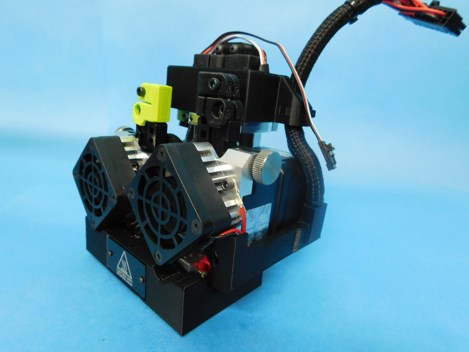
Lets look over this sweet tool head we just made.
Check for the following:
-No pinched wires
-No cross threaded/rounded screws
-Hot tag is flush with the printed part
-Motor wires fully plugged in
-Ground wires tight to hot end
-Tight zipties
-Trimmed zipties
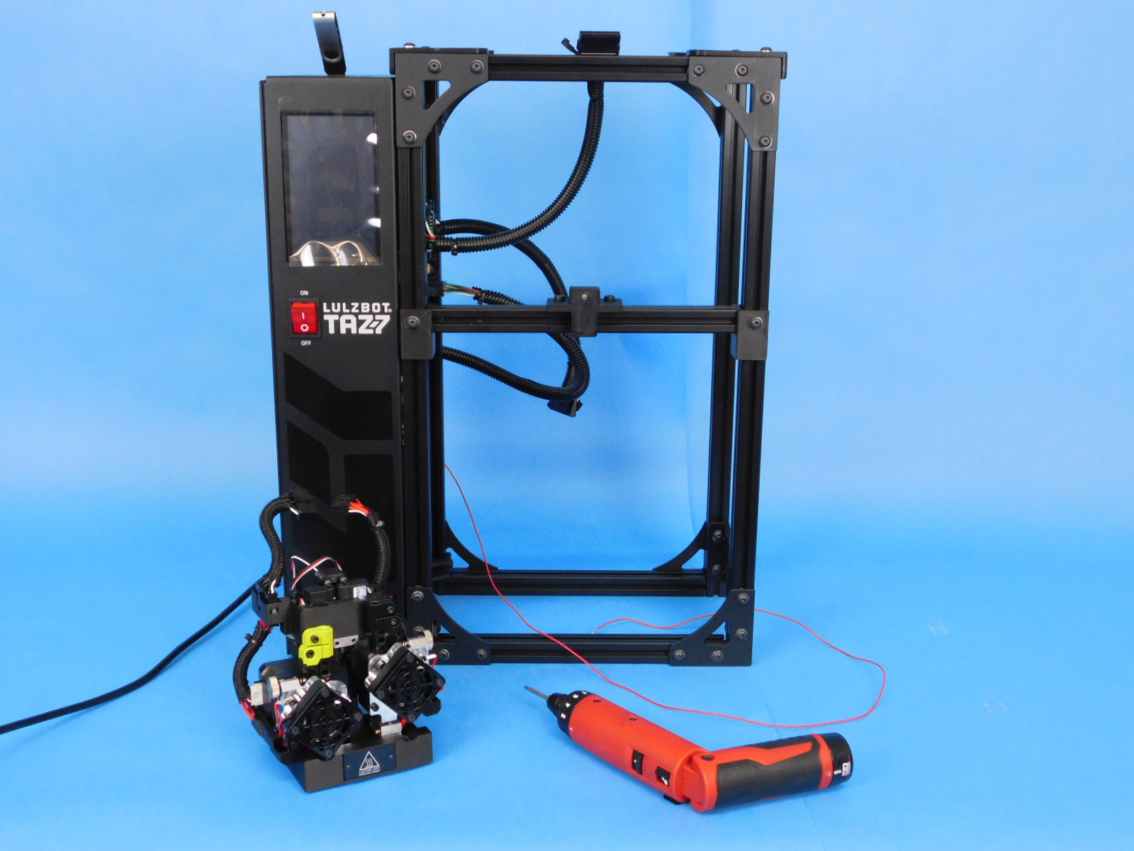
You will need one TAZ Pro Dual Extruder Test Stand
Lay the tool head face down on the table
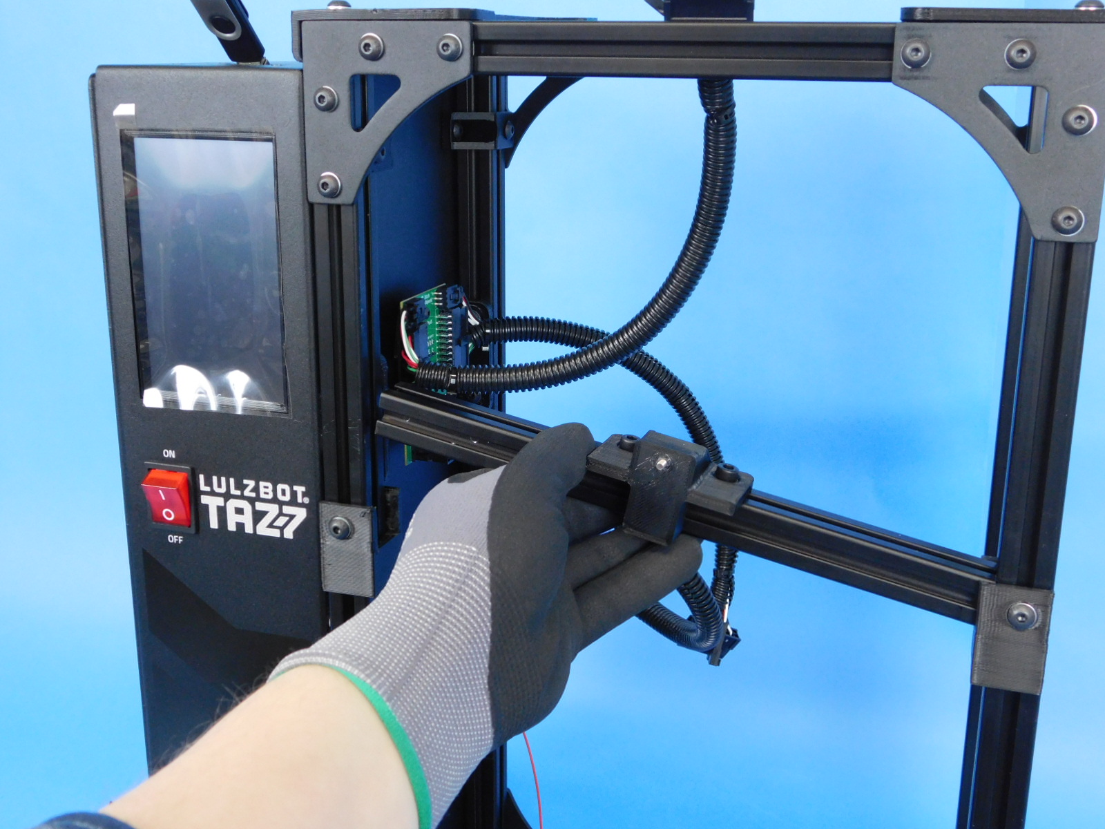
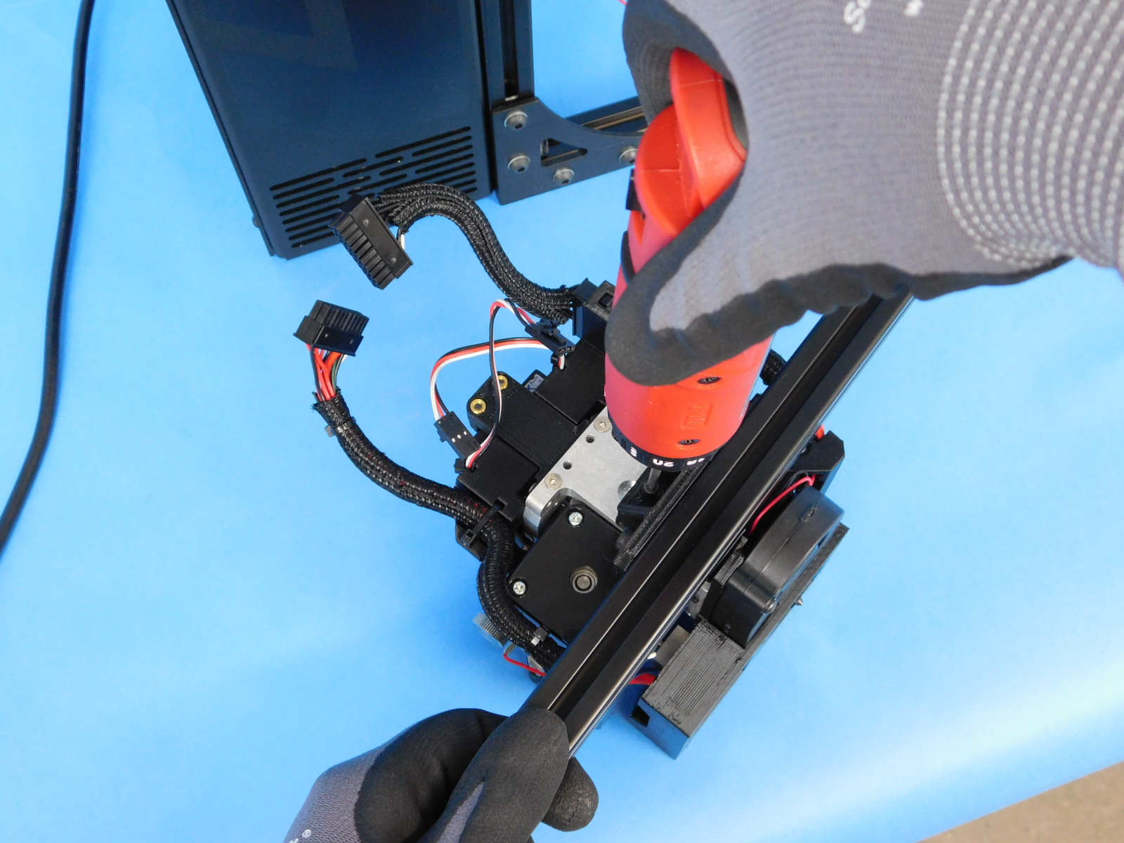
Grab the mount bar from the test stand
Use a 2.5mm driver to secure the tool head to the test stand mount
Place the mount bar with the tool head back on the test stand and connect the harnesses
Power on the test stand
Are both heat sink fans running? If not the unit has failed.
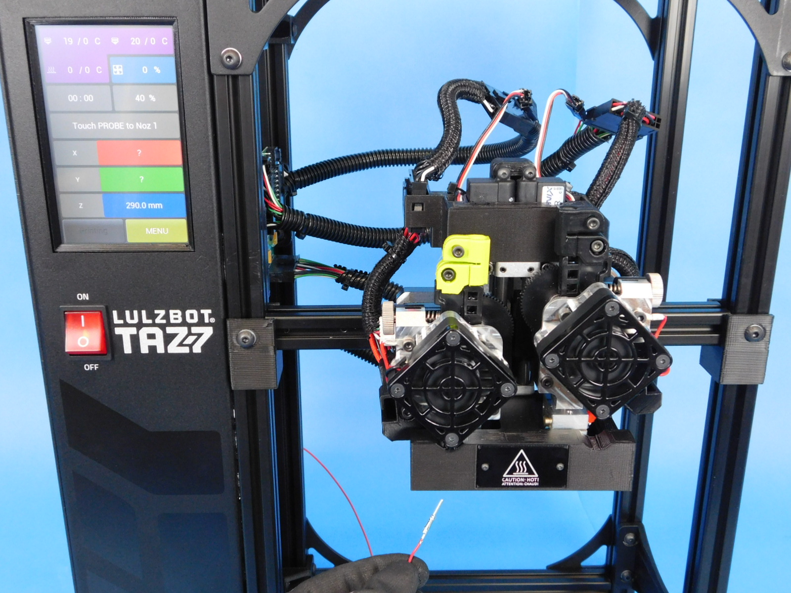
Navigate to the qdualtest.gcode in the USB Drive menu and select "Print"
Grab the probe and touch it to the left nozzle
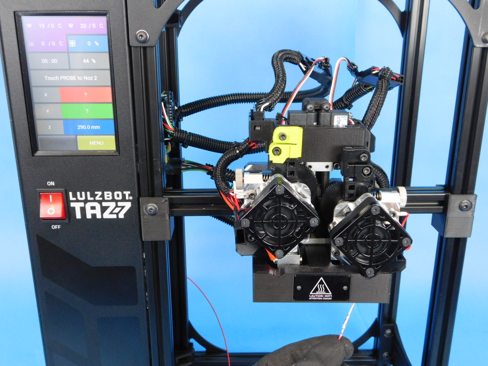
Wait for the tool head to switch to the right nozzle
Touch the probe to the right nozzle
While switching extruders, watch the blower shroud and both movements to ensure no interference or binding occurs.
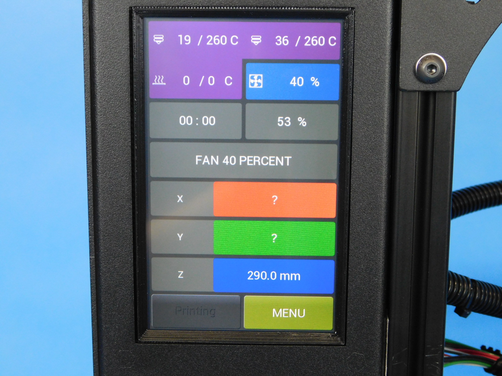
You must observe the following:
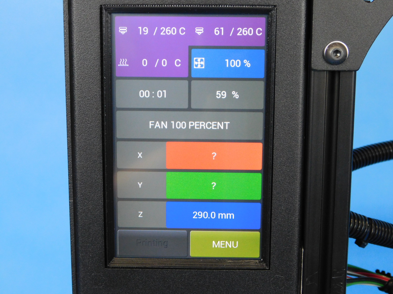
The test stand will now cycle the cooling fan, first at 40%, and then again at 100%. Verify the fan spins at both speeds.
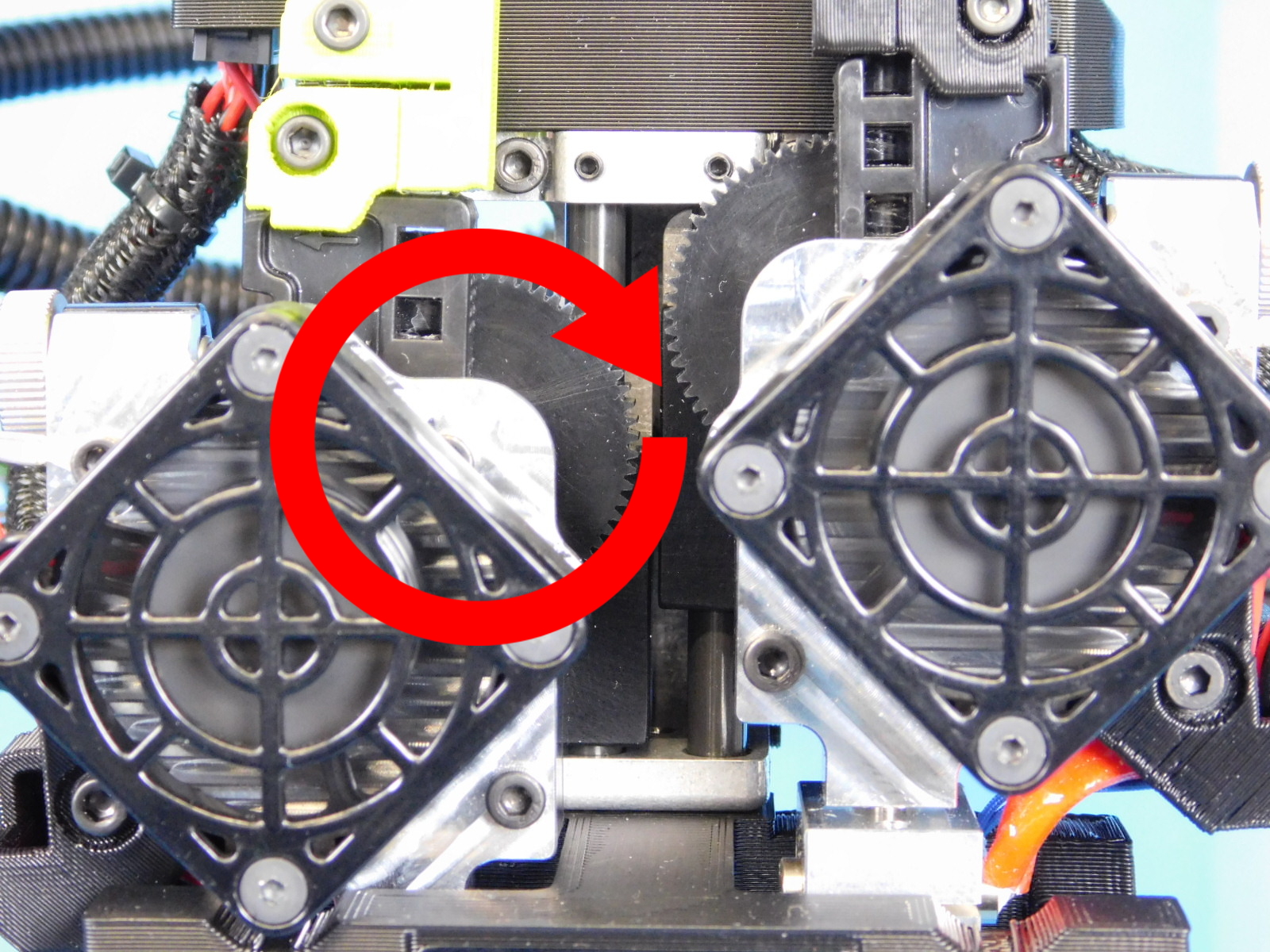
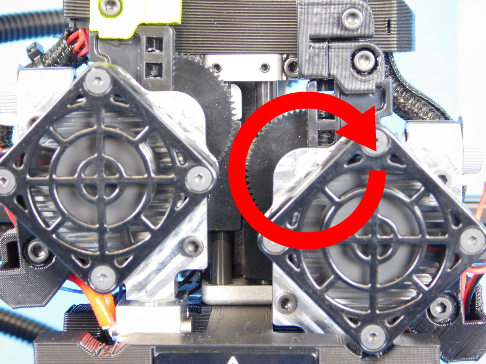
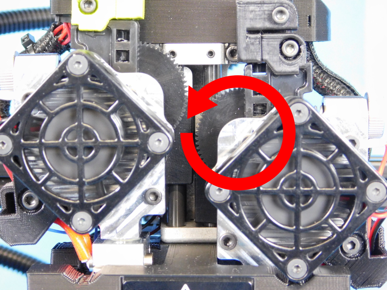
Both hot ends will heat to 260C and then the test stand will cycle both extruder motors in both directions.
Visually ensure the motors move in the correct direction!
The hot ends will then cool to 70C for handling before completing the test gcode, utilizing the cooling fan to slightly accelerate the cooling time.
MINTEMP, MAXTEMP, and HEATING FAILED are possible failure modes.