Open HardwareAssembly Instructions
Guides for installation and assembly of the LulzBot line of products made by Aleph Objects, Inc.
Guides for installation and assembly of the LulzBot line of products made by Aleph Objects, Inc.
Observe ESD mitigation practices: Take steps to prevent accidental damage to sensitive electronics by following ESD prevention guidelines

Turn the power switch to off and make sure both the power cord and USB cord are unplugged.

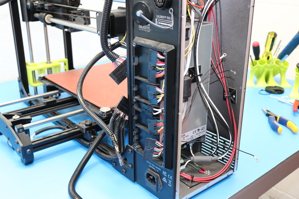
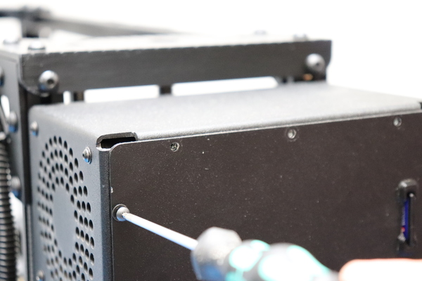
Using a 2 mm hex key, undo the fasteners holding the case cover.

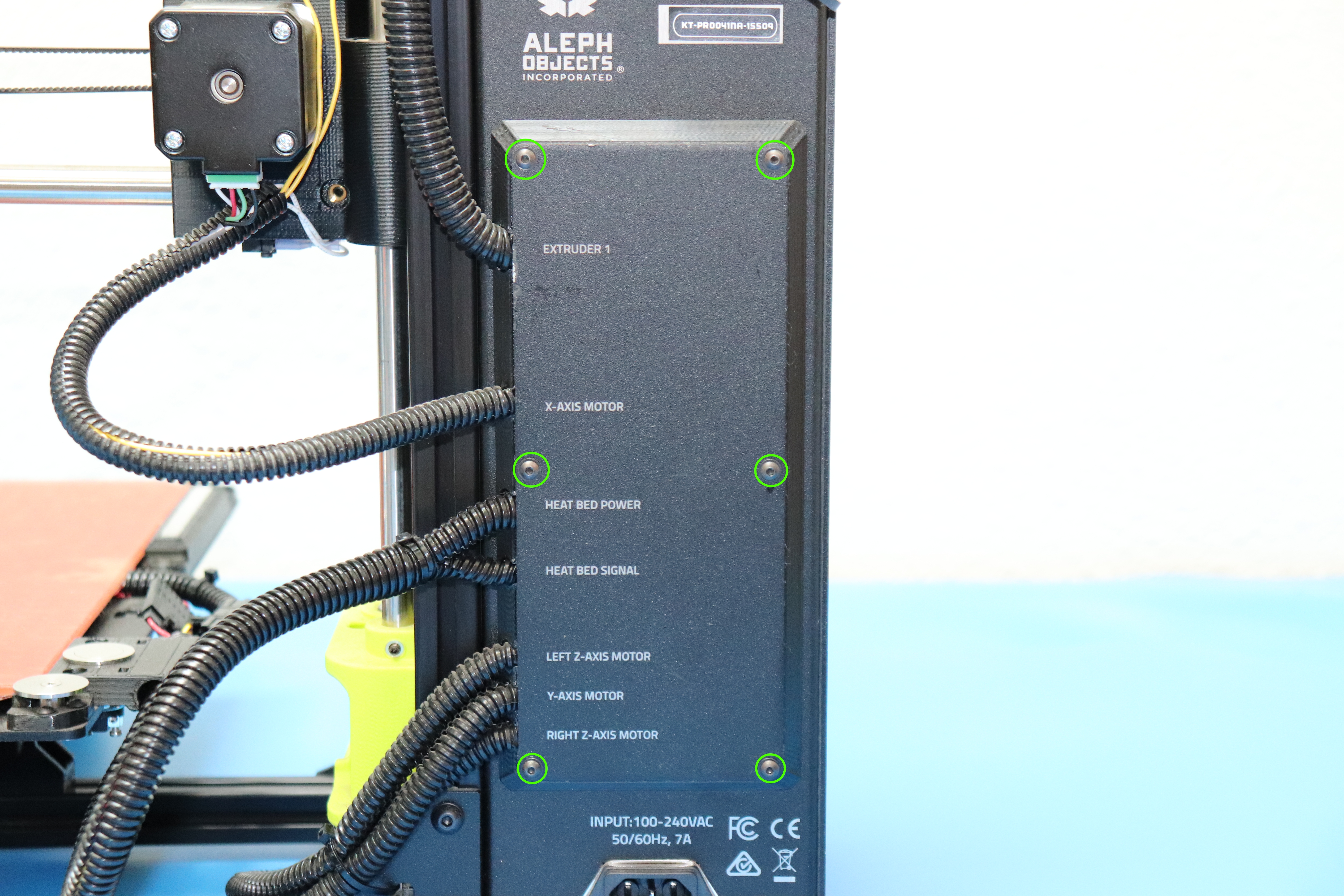
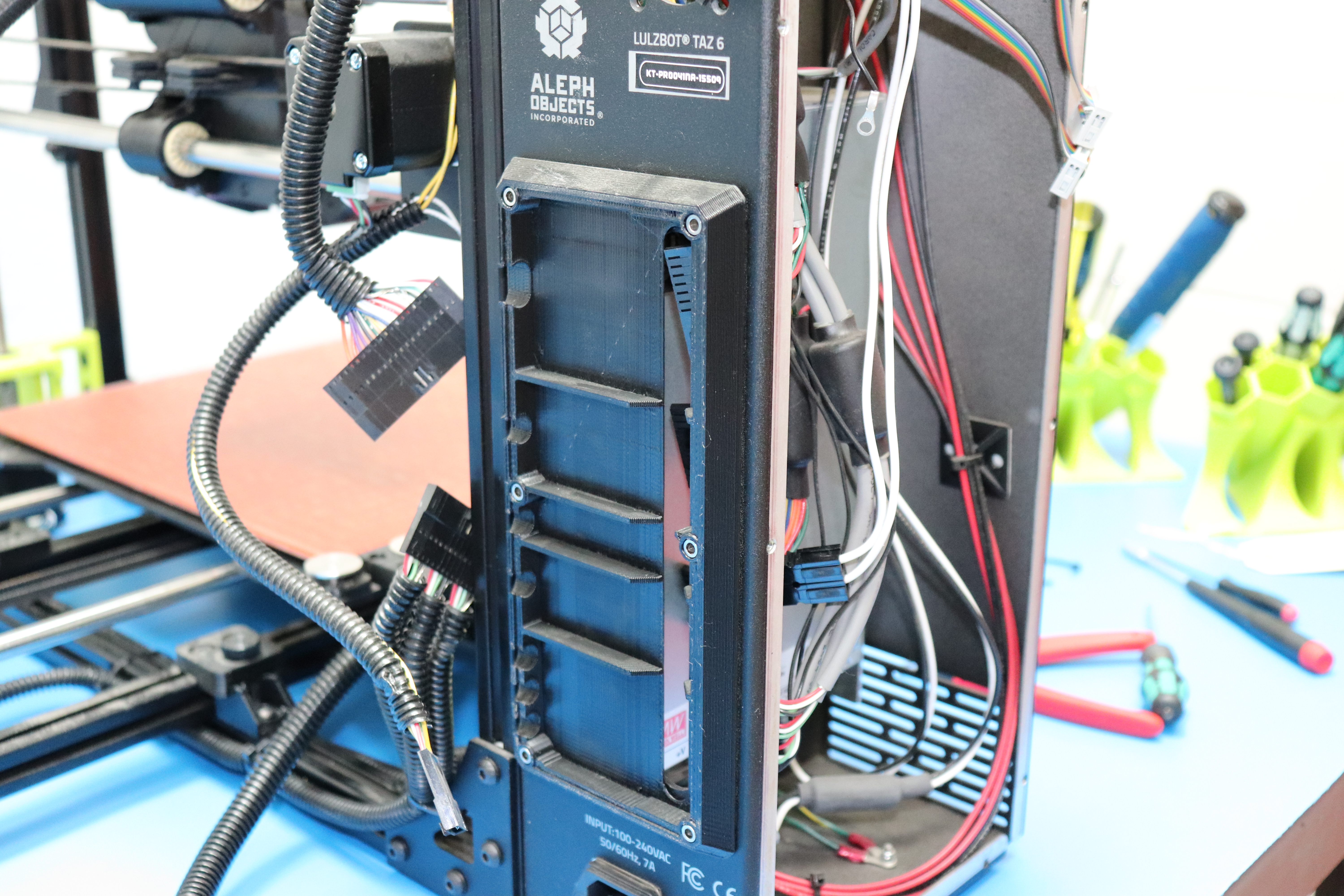
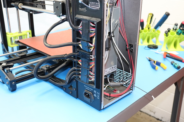
Using a 2 mm hex key, remove the fasteners holding the interconnect cover.
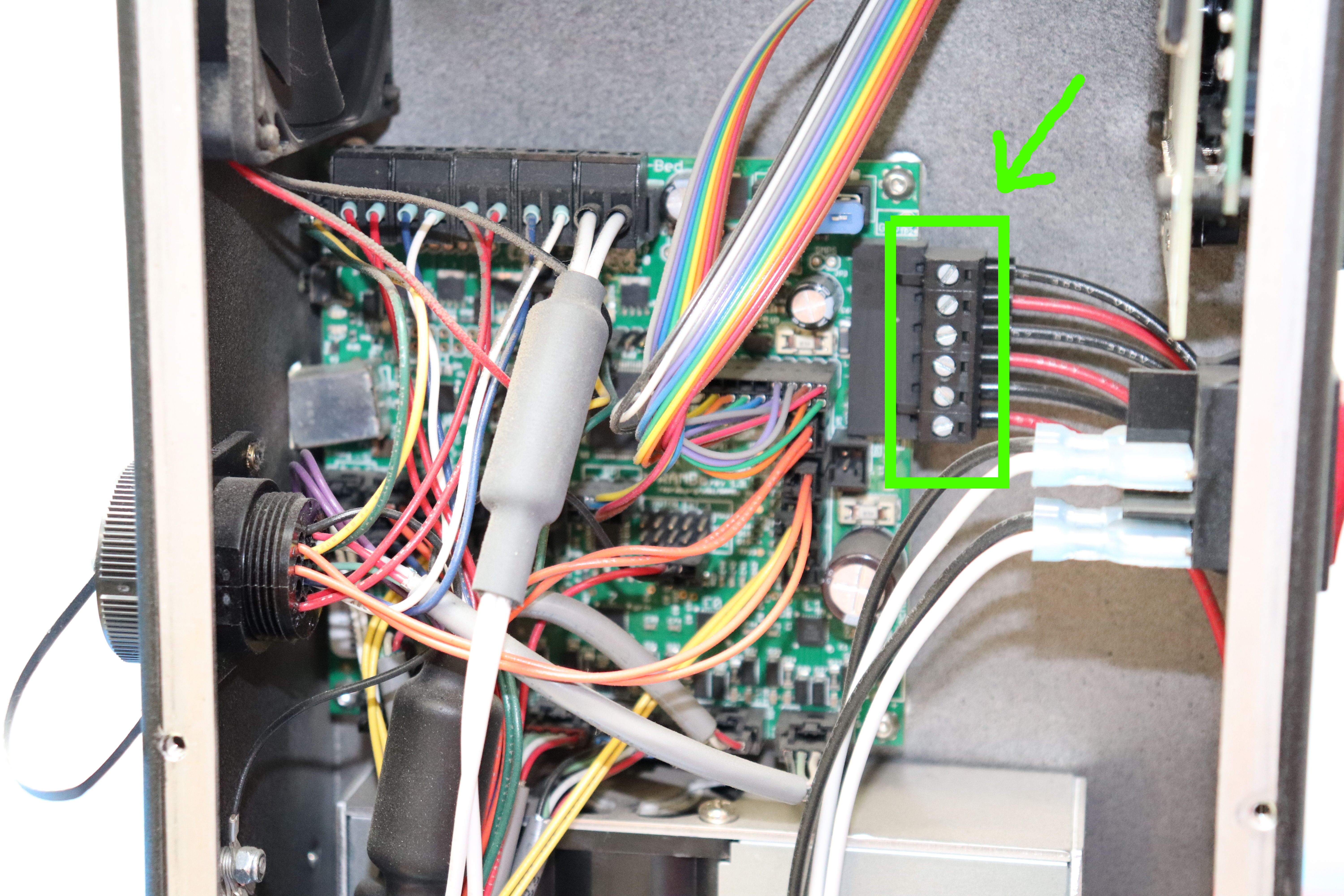
Disconnect the power connector from the board.
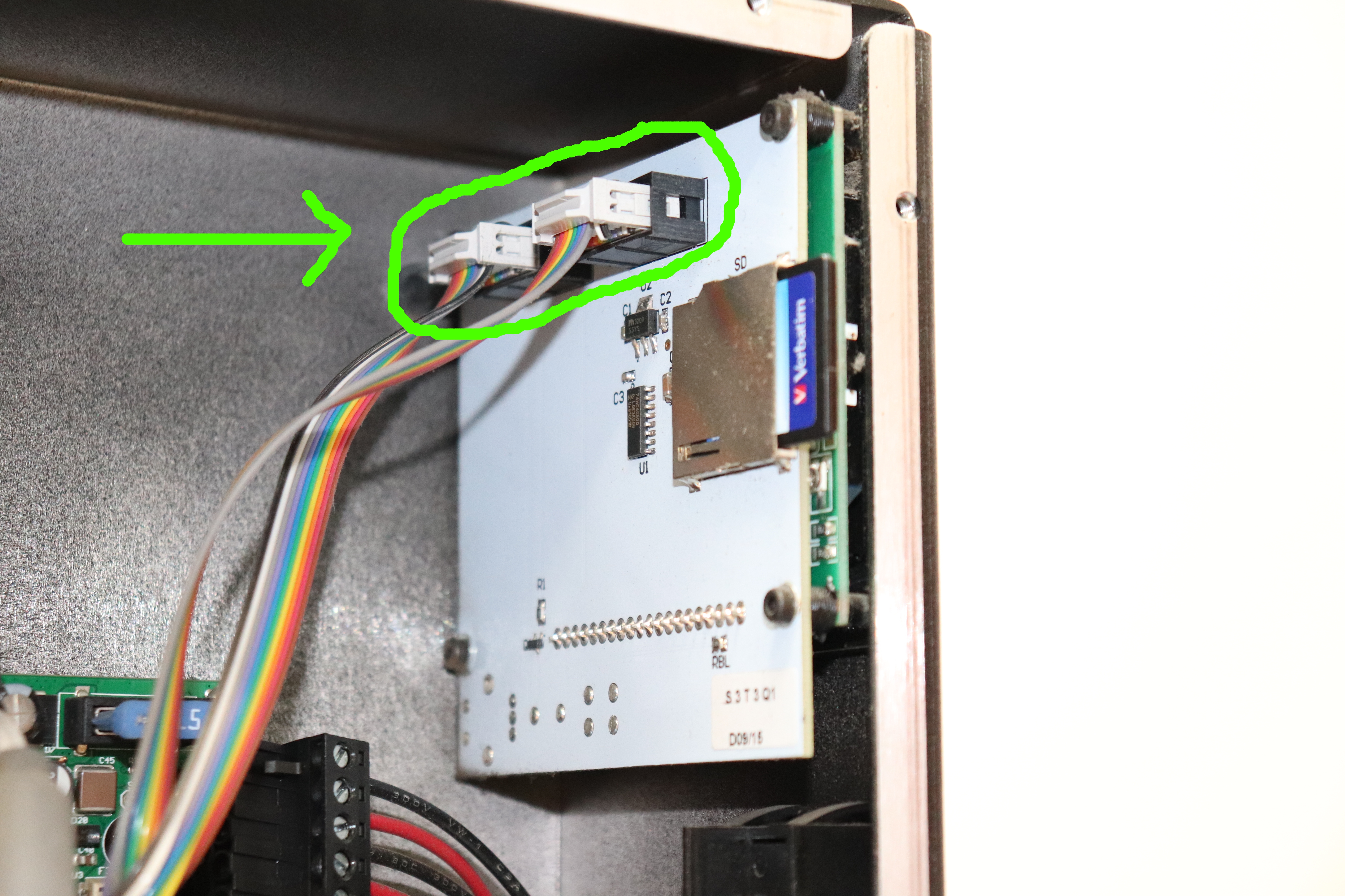
Disconnect the LCD cable harnesses from the LCD screen assembly.
Disconnect the case fan.

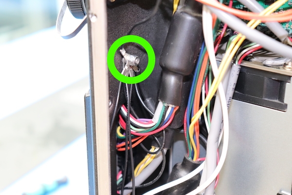
Using a 5.5 mm driver, disconnect the grounds.

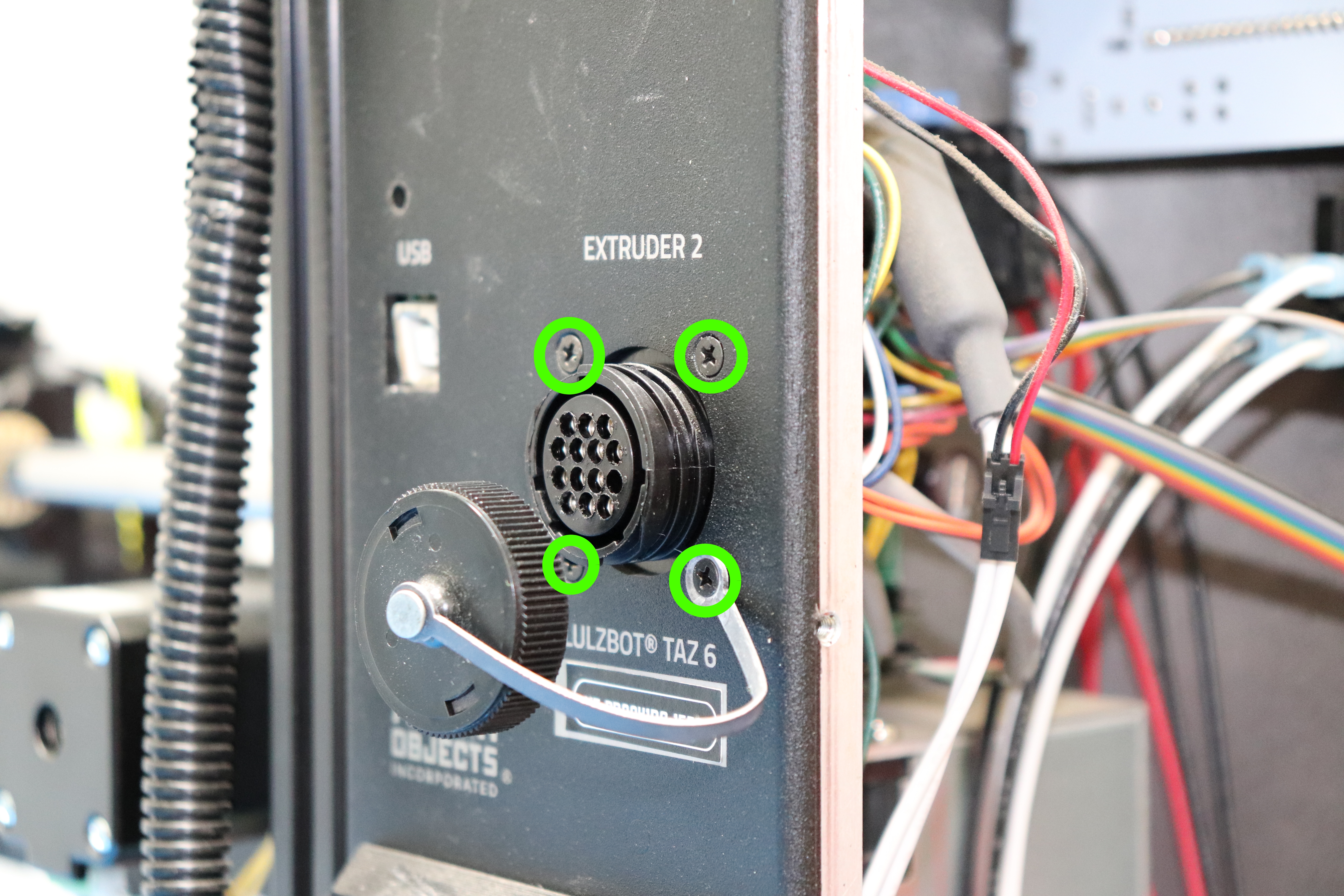
Using a #1 phillips head screwdriver, remove the dual extruder port connector housing.
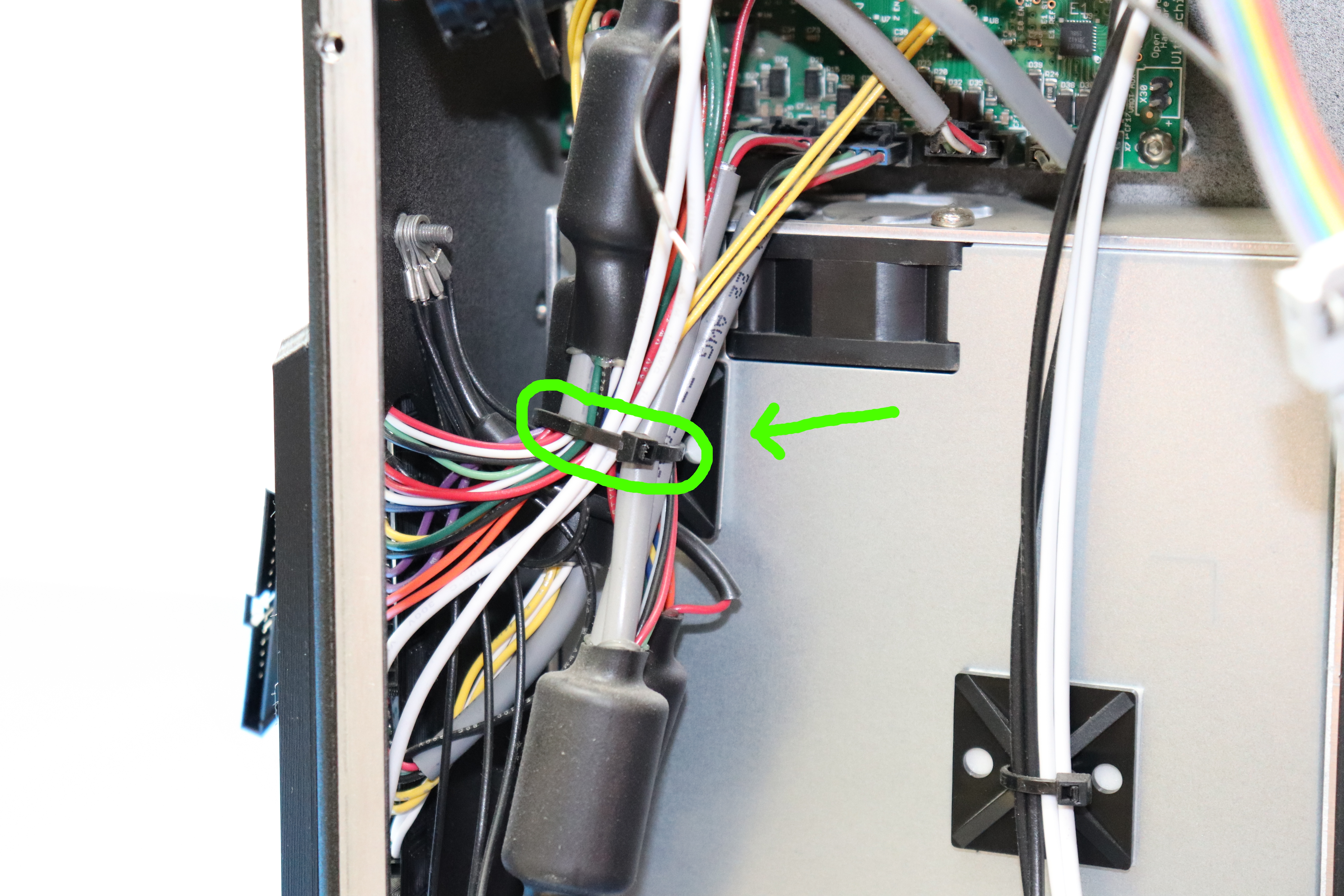
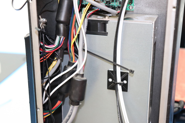
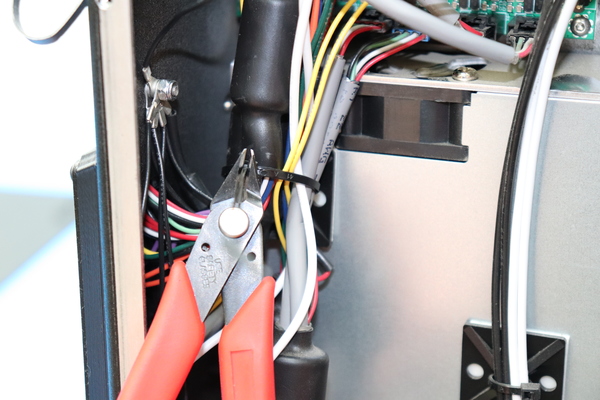
Cut the zip tie holding the internal harnesses.
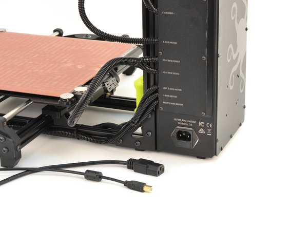
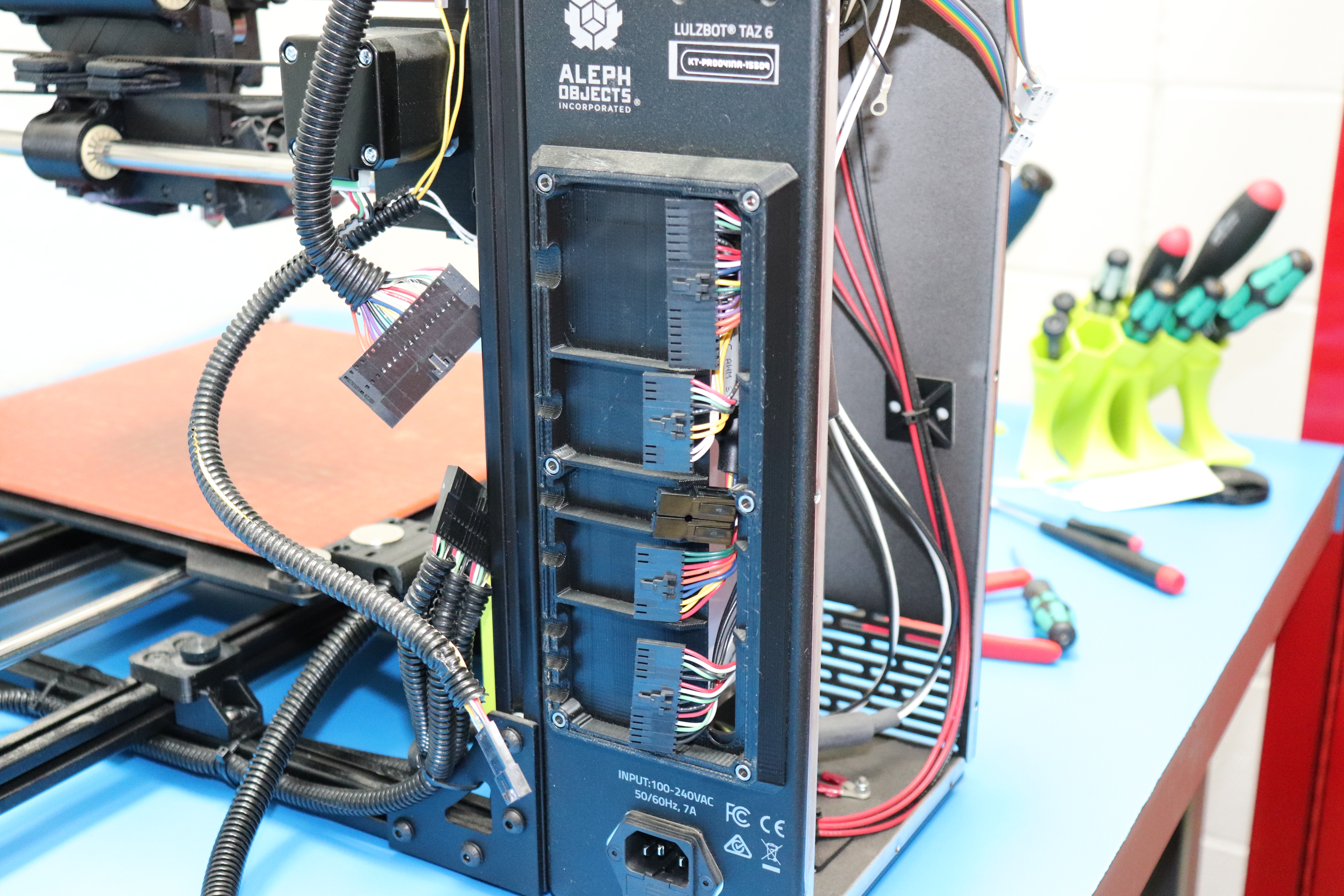
Unplug all the internal harnesses from the external harnesses.
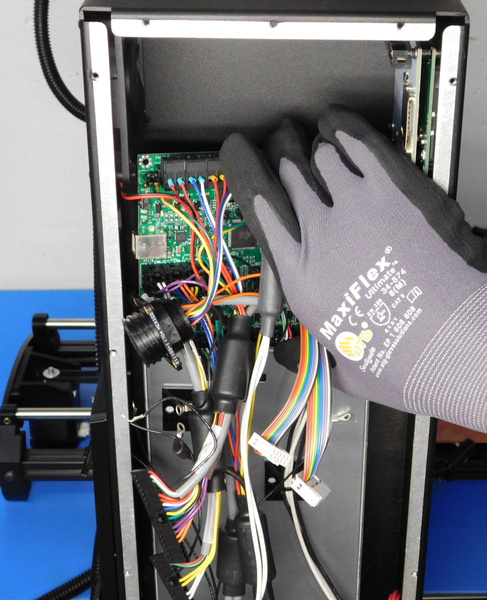
Carefully feed the internal harness connectors though the hole in the case into the case.
Using a 2 mm hex key, unscrew the four stainless fasteners that hold the RAMBo in the case. They are at the four corners of the board.
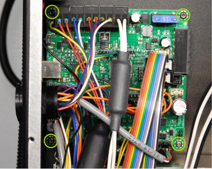
Carefully remove the board with the harnesses attached from the case. Check for any harnesses that may have been left connected to the case and disconnect them.
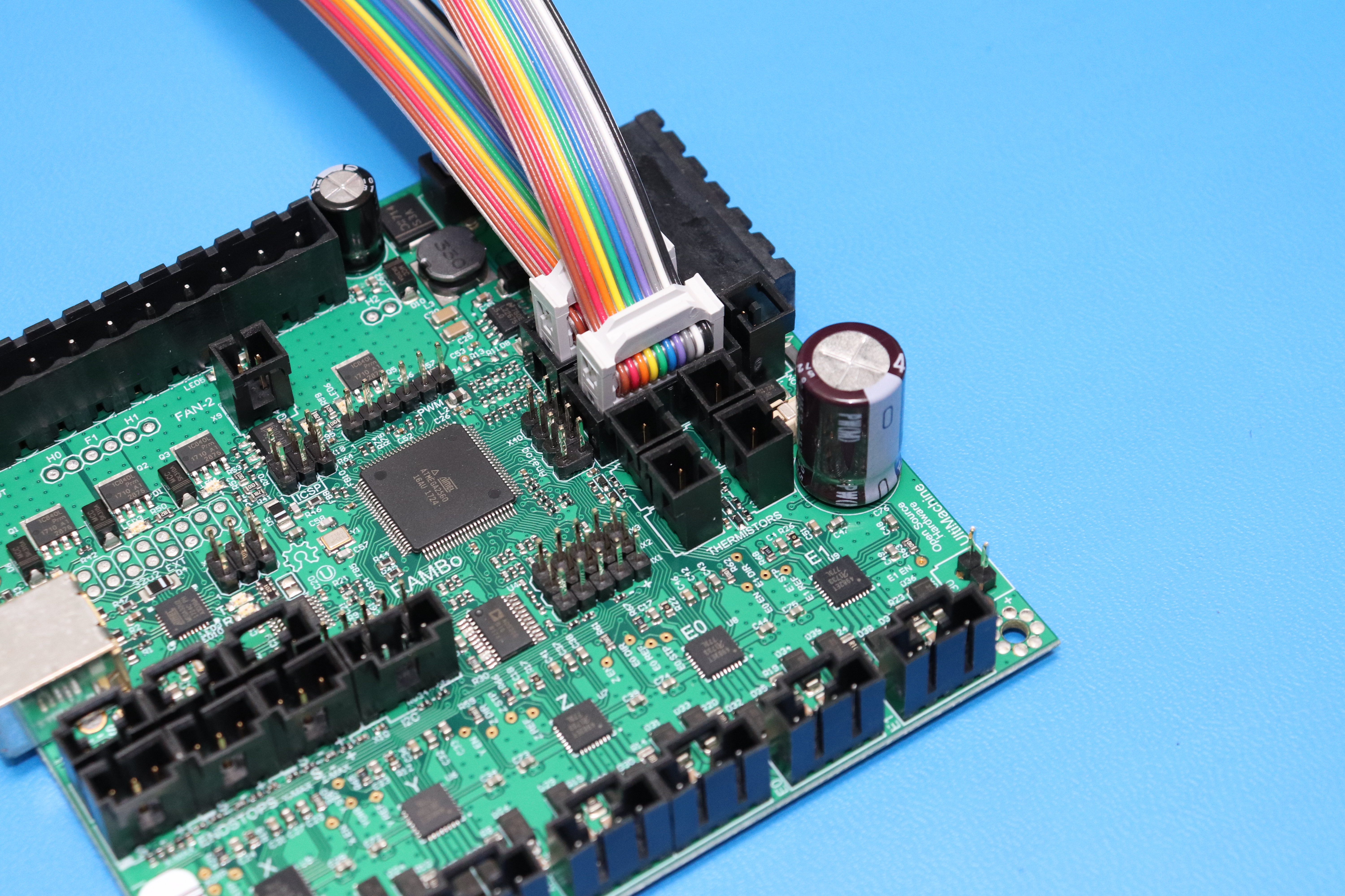
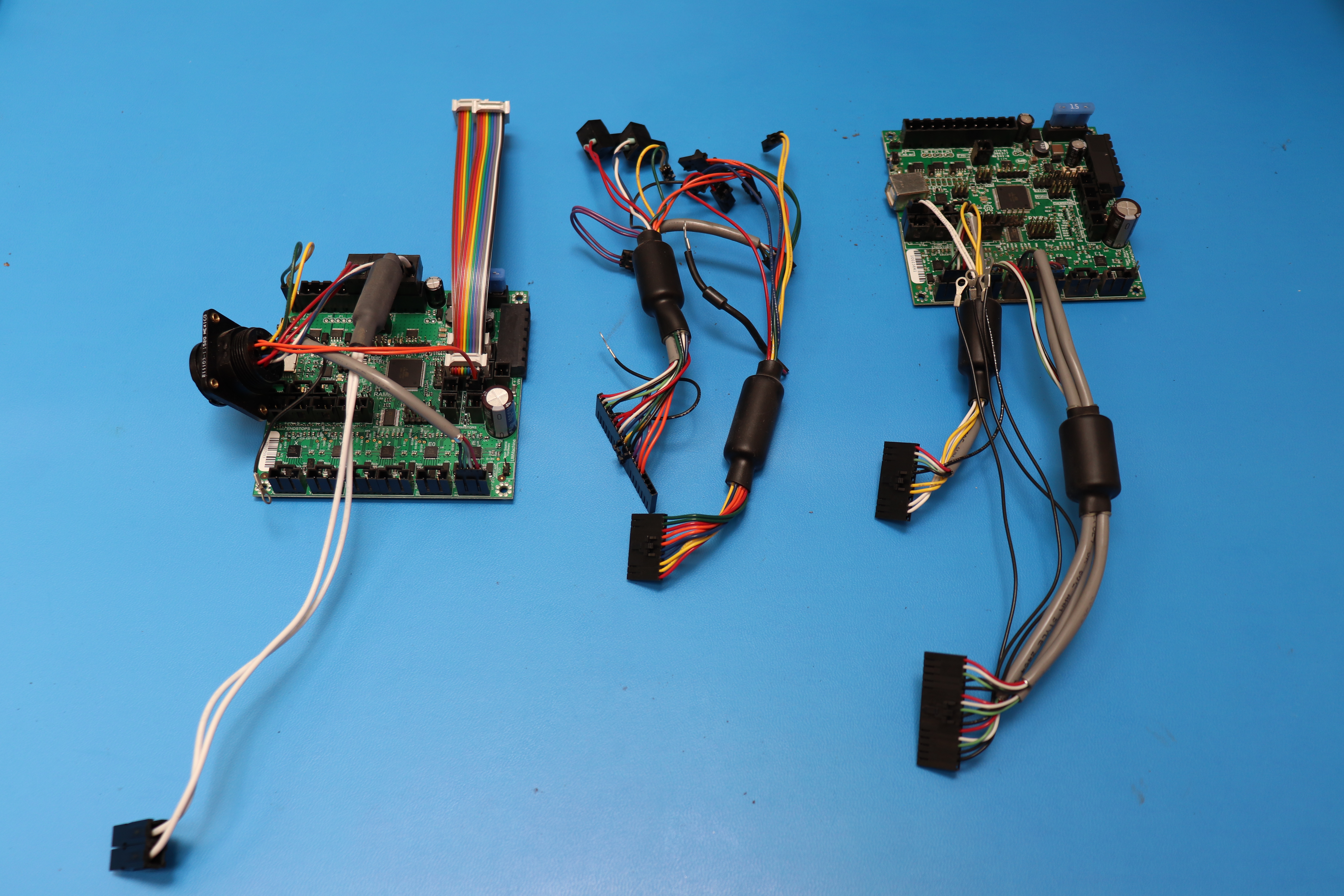
Make sure to take note of the orientation of all connectors before unplugging them.
15A
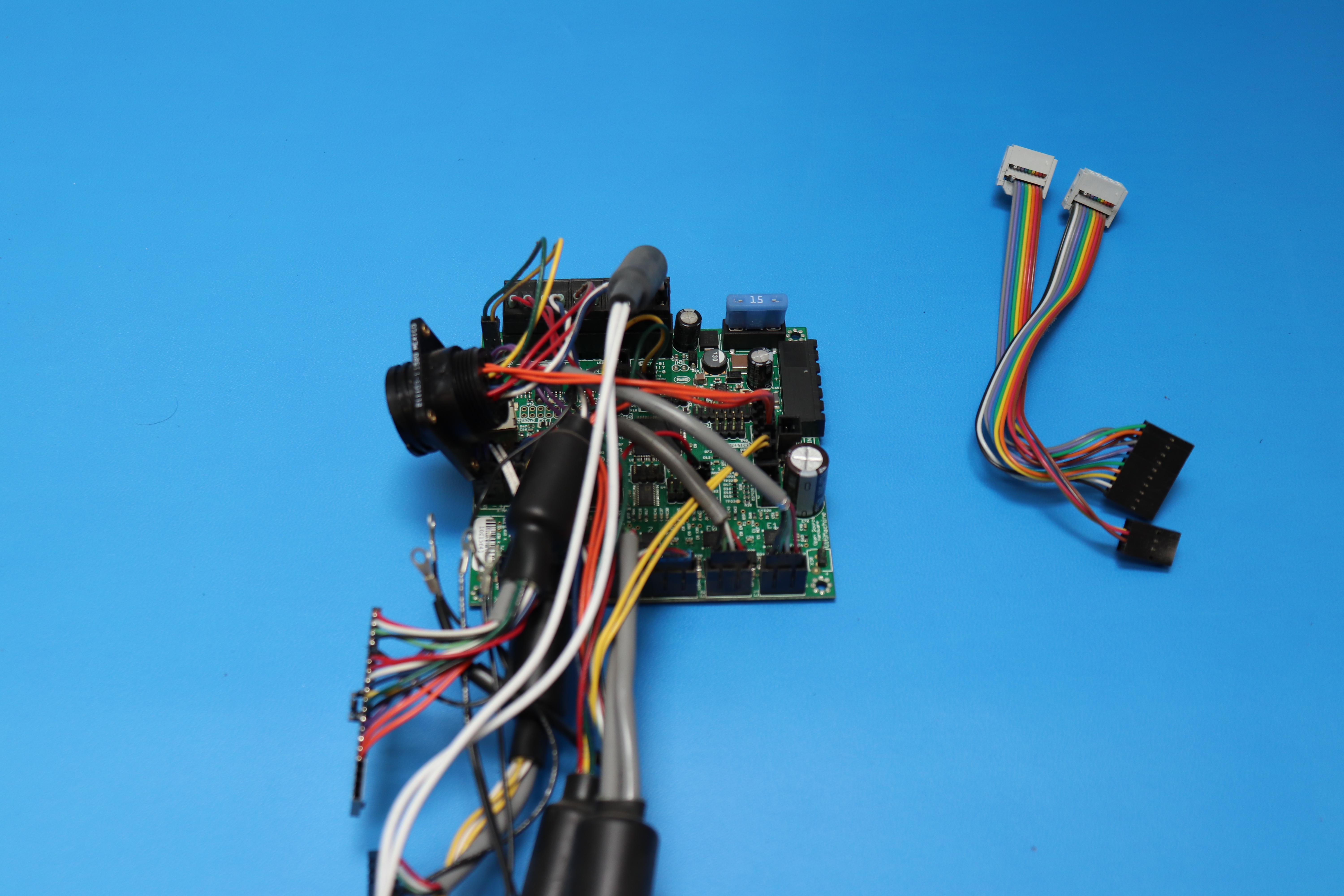
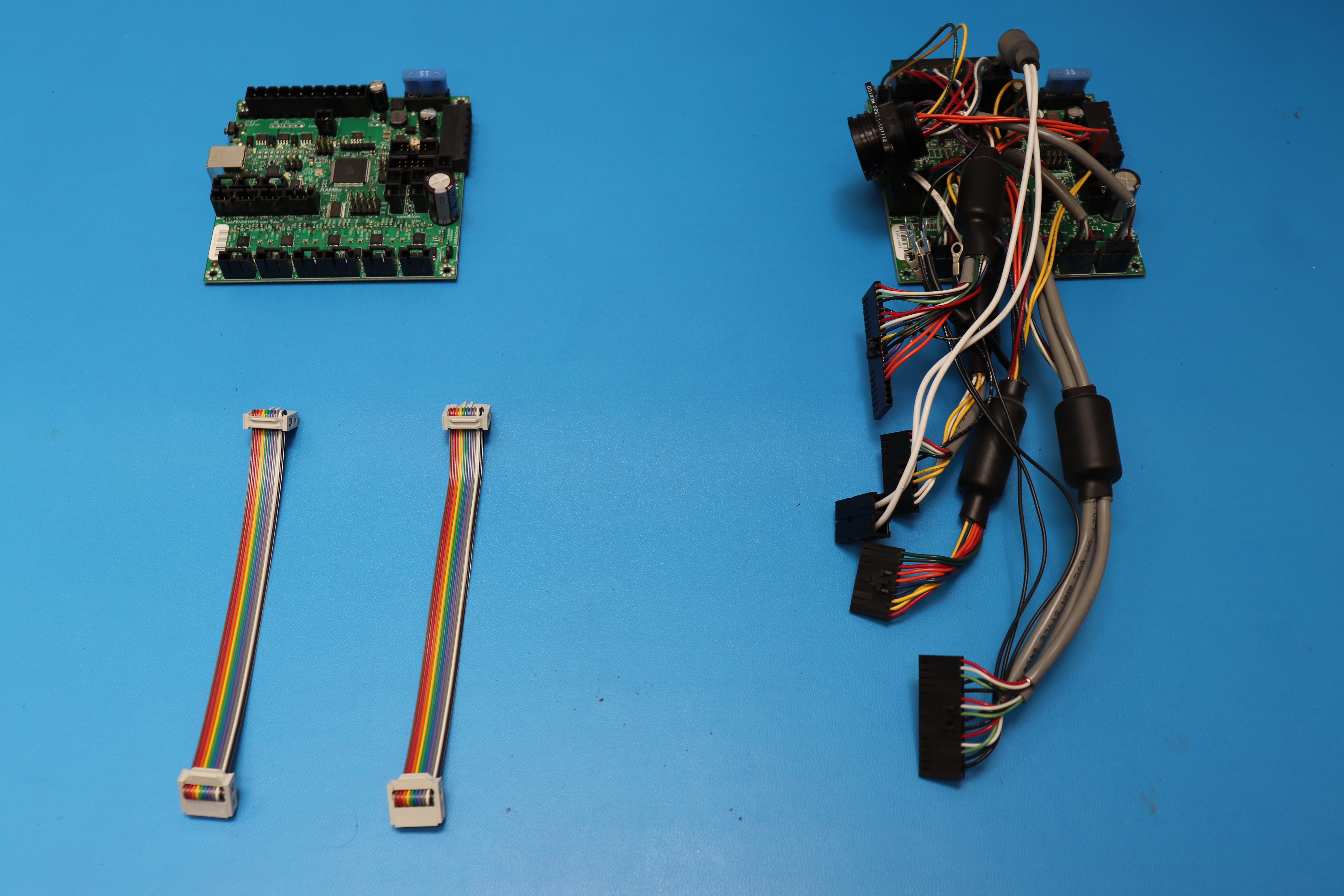
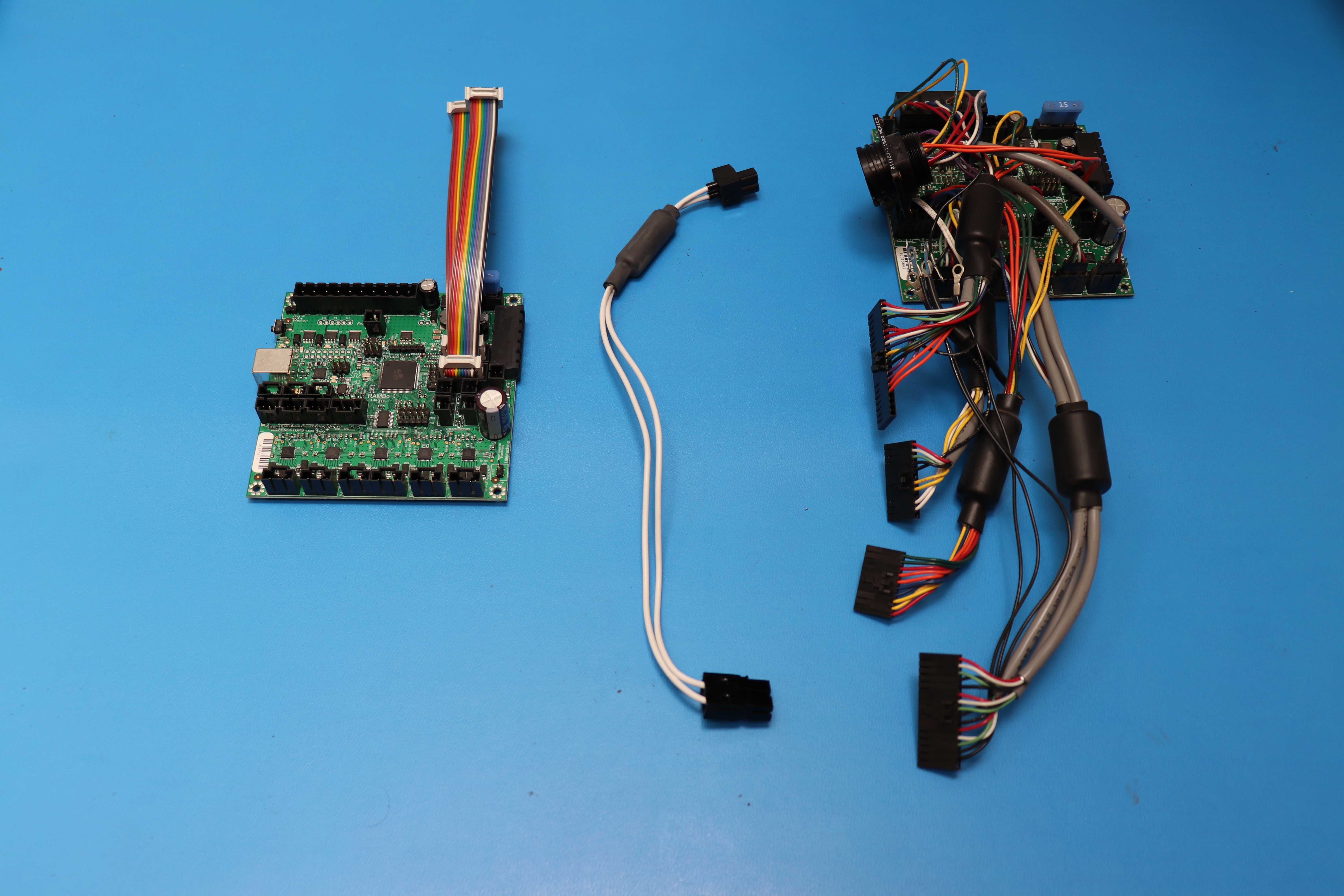
Remove the LCD harness from the 1.3L RAMBo and set them aside. Install the new 1.4 RAMBo LCD harnesses onto the new RAMBo as shown in the picture.
15B
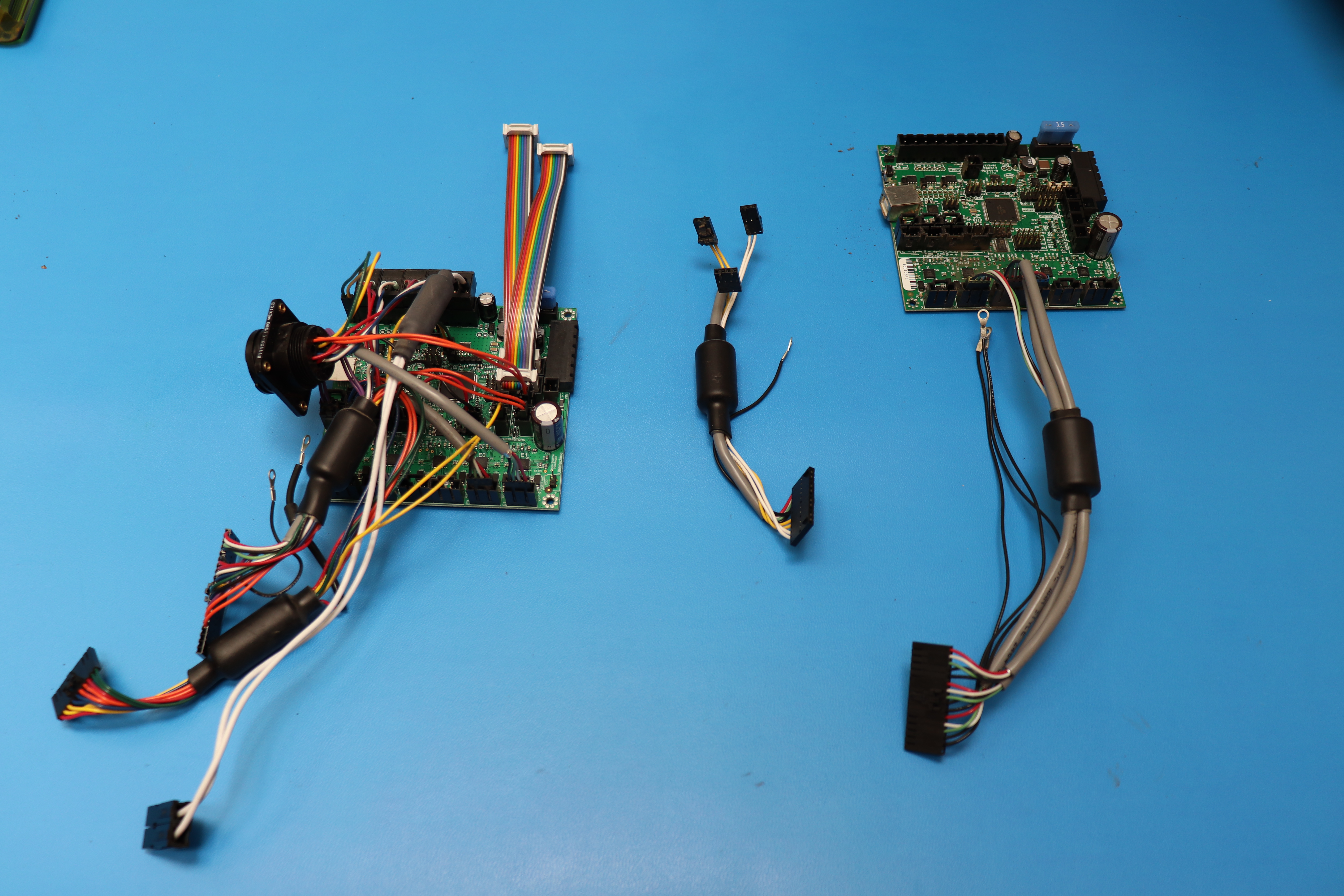
Remove the bed power harness and transfer it to the new RAMBo.
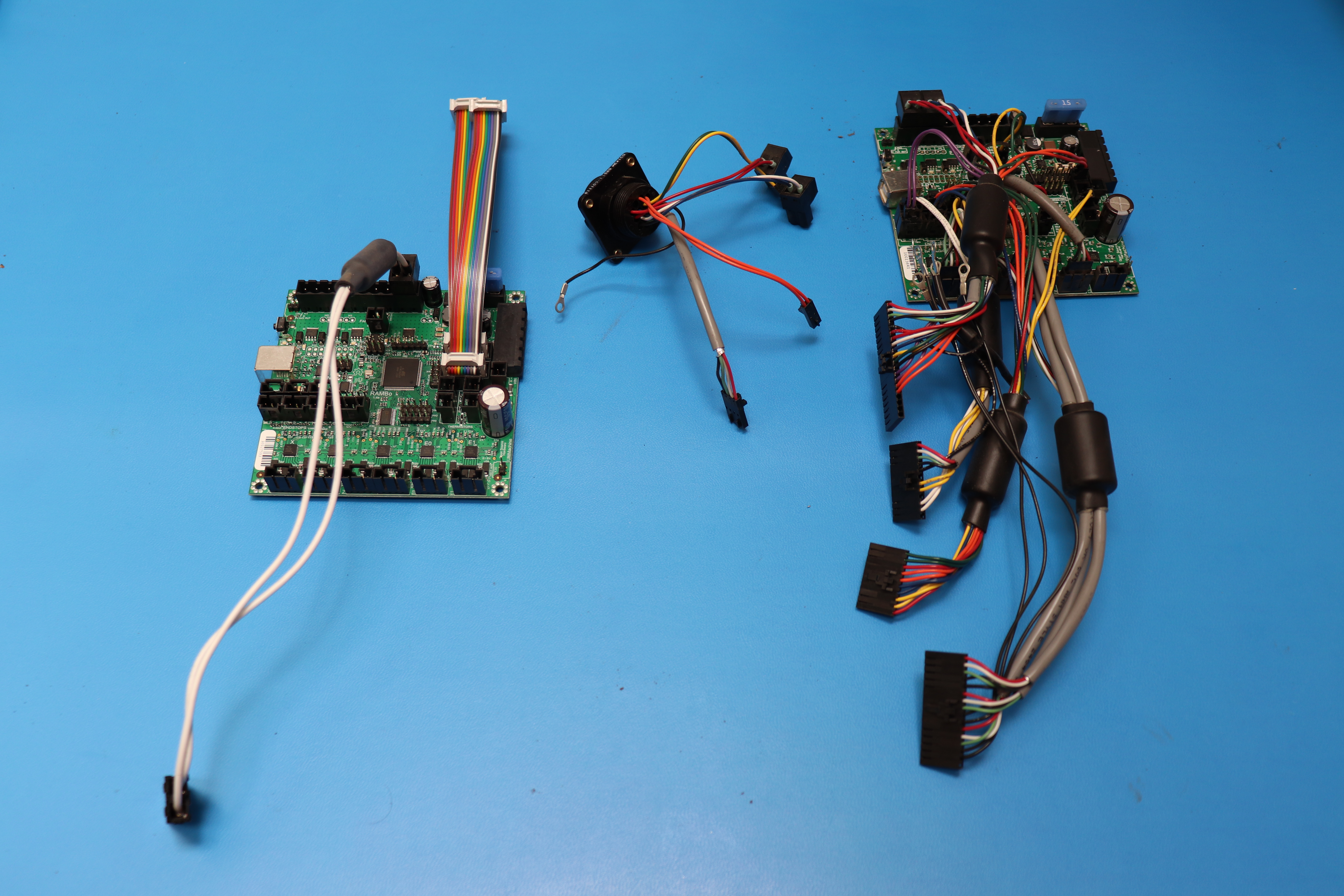
15C
Remove the dual extruder harness and transfer it to the new RAMBo.
15D
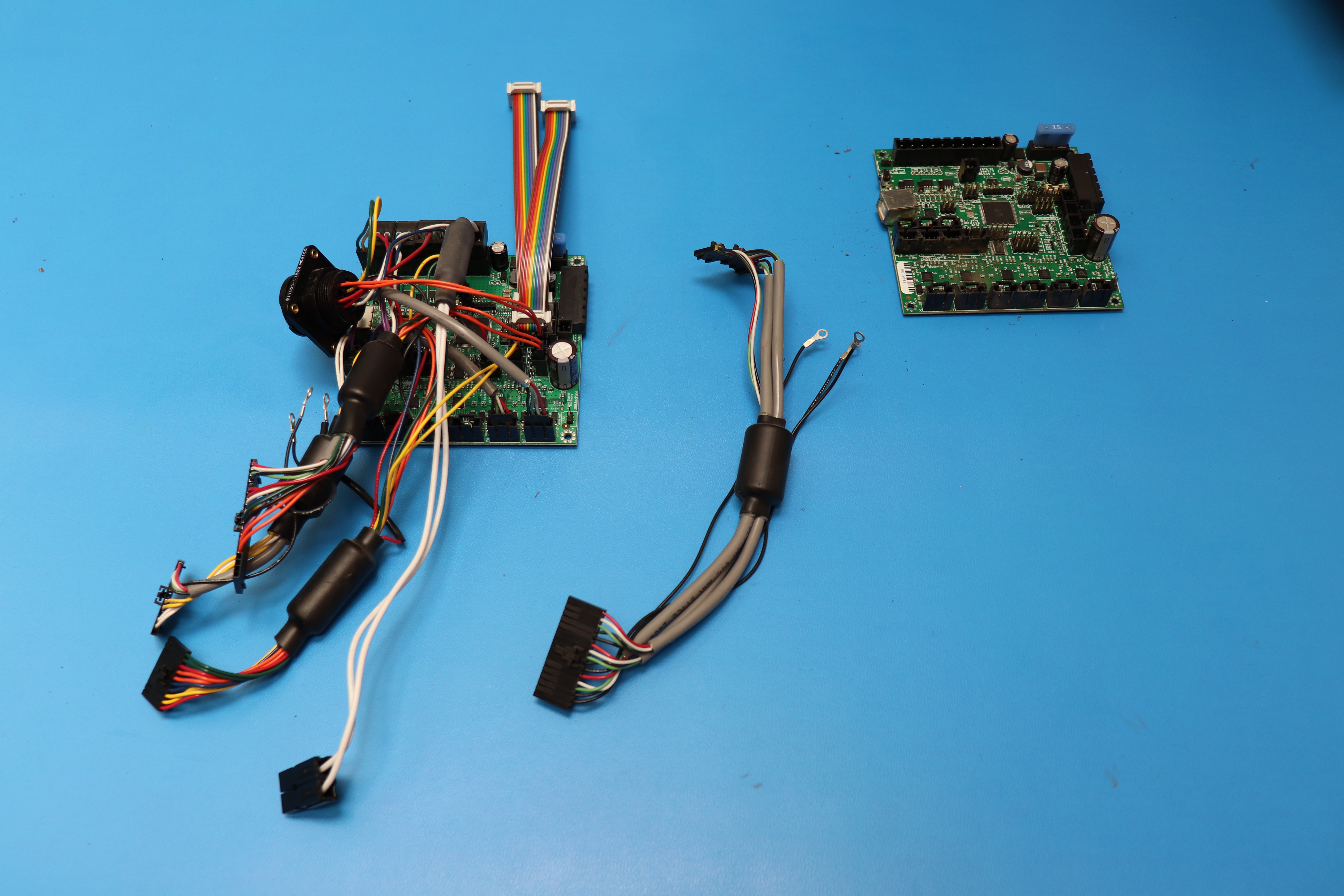
Remove the YZ harness and transfer it to the new RAMBo.
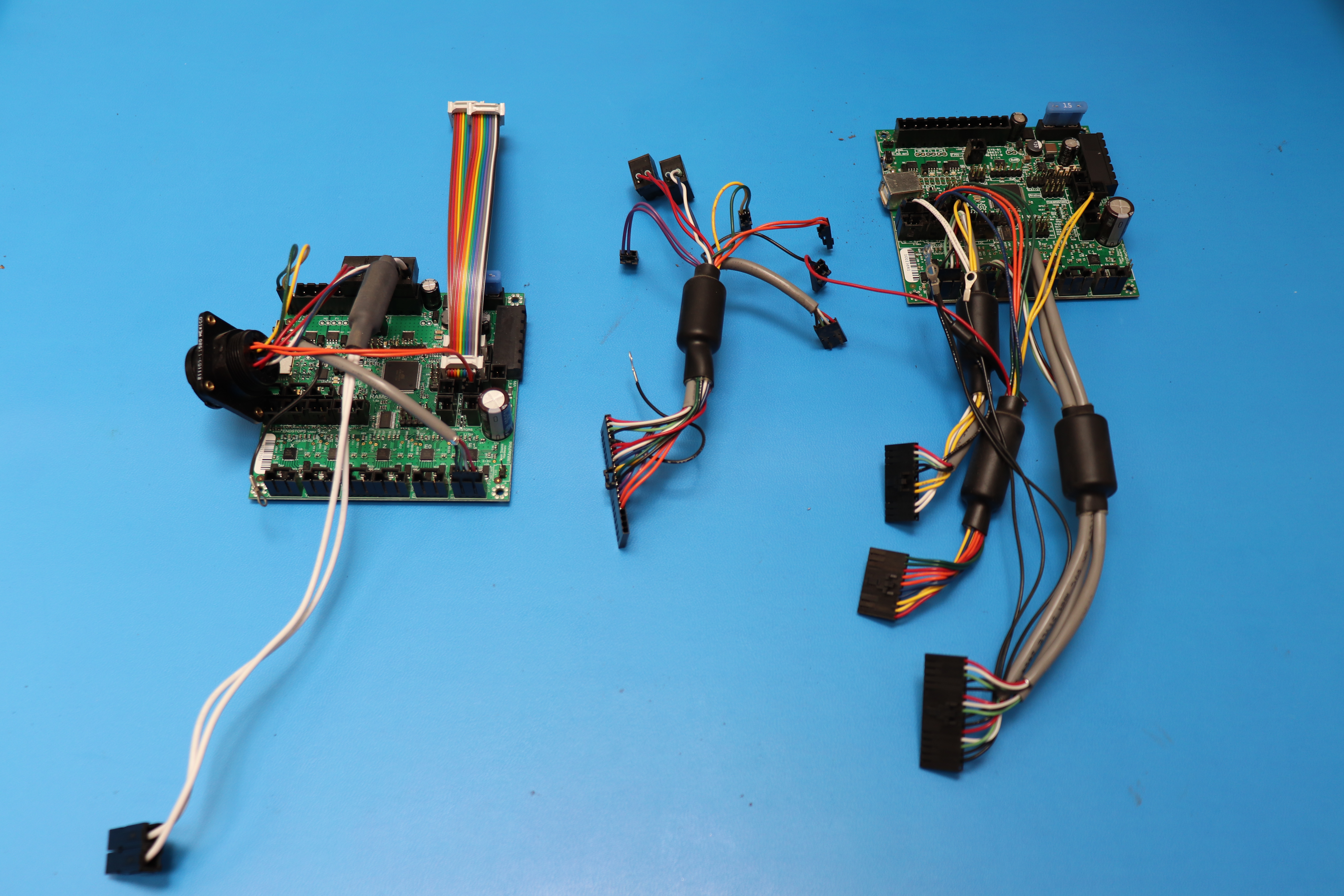
15E
Remove the endstop harness and transfer it to the new RAMBo.
15F
Remove the YZ harness and transfer it to the new RAMBo.
16A
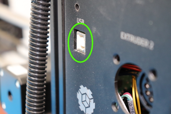
Move any wires remaining in the case out of the way and install the RAMBo assembly, making sure the USB connector goes into the hole in the sheet metal first
16B
Use the four Stainless Steel Button Head screws to mount the RAMBo assembly.


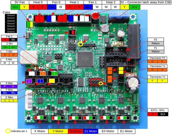
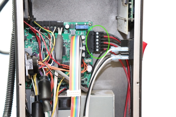
Connect the power harness to the RAMBo. Make sure the connector housing seats fully.
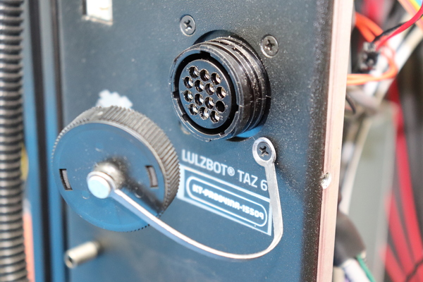
Install the extruder 2 port connector housing and secure using the four Phillips head screws.
Note: Use one screw to secure the connector cover strap.
Carefully reconnect the case fan to the case fan connector as shown.

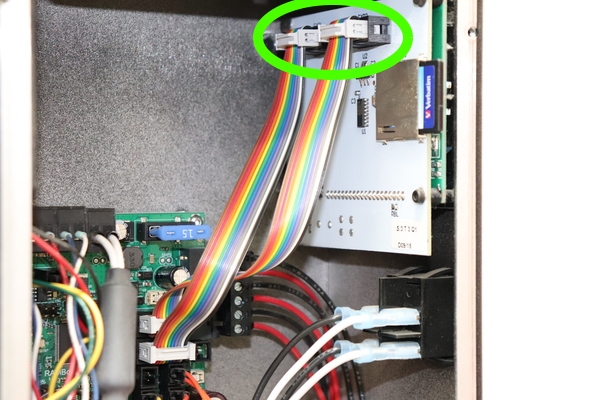
Reconnect the LCD harnesses as shown. The cable that connects towards the bottom of the printer on the board connects to the connector towards the inside of the case.
Carefully feed the internal wiring harnesses through the hole in the side of the electronics enclosure towards the outside of the case.
Connect the connectors in the interconnect housing. Make sure each connector is seated fully.
Using the locknut, tighten the seven ground lugs onto the ground post. Do not over tighten.
Install the zip tie onto the tie base as shown.
Align the SD card holder with the slot in the main case cover and install the cover with the screws. Then carefully install the interconnect housing cover making sure not to pinch any wires.

Plug in the power cord and turn on your 3D printer.
Follow the instructions found here to update the firmware on your printer: LulzBot.com/Firmware.
Have Questions? Reach out the the support team at LulzBot.com/Support