Open HardwareAssembly Instructions
Guides for installation and assembly of the LulzBot line of products made by Aleph Objects, Inc.
Guides for installation and assembly of the LulzBot line of products made by Aleph Objects, Inc.
Need to ship or travel with your LulzBot TAZ? Follow the instructions below to properly secure your TAZ 3D printer.
Want extra or replacement packaging material? Contact our sales team by sending an email to: Sales@LulzBot.com. Due to the custom nature of the shipping material, replacements are available for purchase only.
Note: Failure to use the original packaging material when returning a 3D printer for warranty service will cause delays and may require additional charges.
Printers that are received without the original packaging materials may be returned to sender.

Note: Pack your 3D printer on carpet or other soft surface to keep your 3D printer free from scratches
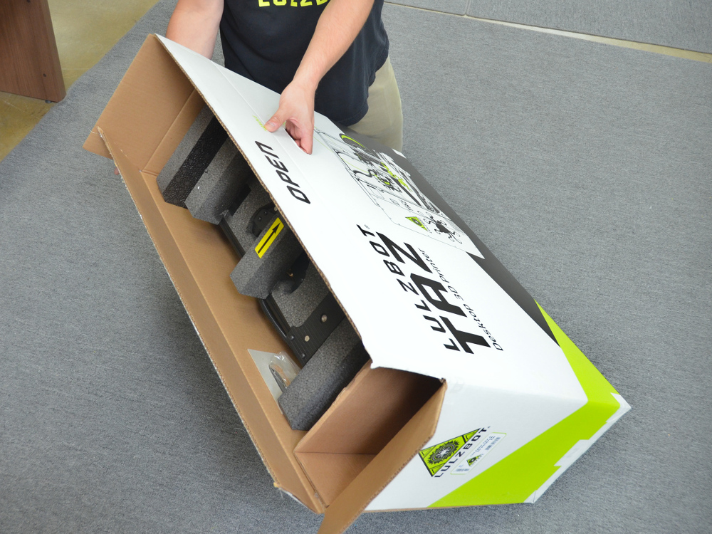
TAZ 6 3D Printer Box
Accessory Box
Tool Head Box
Additional Items Recommended


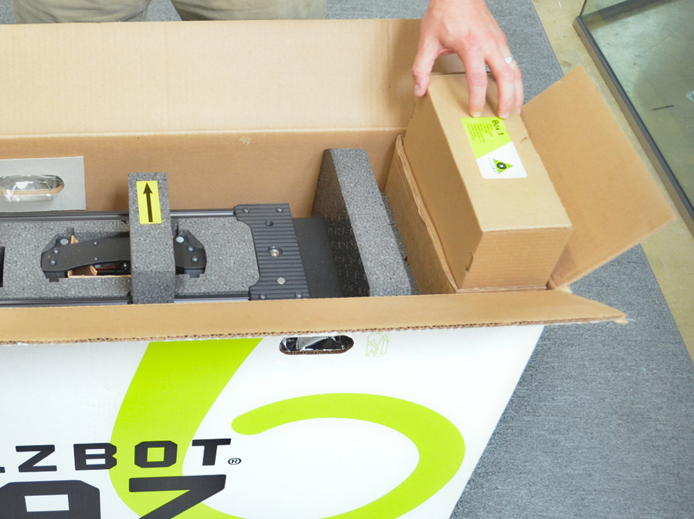
Remove and set aside the Accessory and Tool Head boxes from the side of the TAZ 3D printer box.
4A
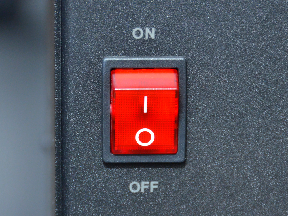
With your TAZ 3D printer plugged into an AC power outlet, power on your TAZ 3D printer.
4B
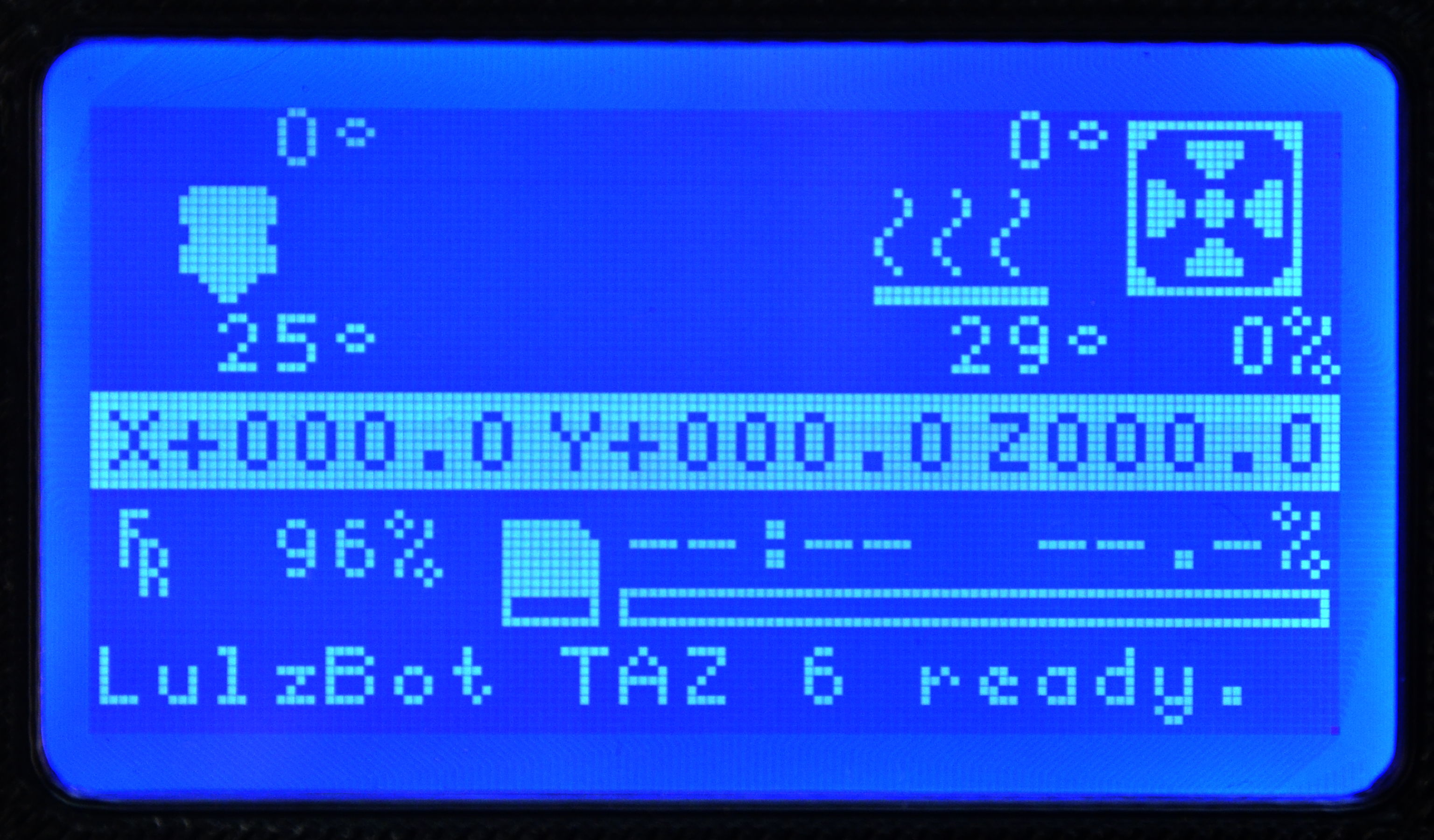
Home the Z-axis with the Graphical LCD controller (GLCD). Press in the knob and select: Movement > Auto home.
4C
Using the GLCD, select: Movement > Move axis > Move 10mm > Move Z.
4D
Rotate the knob to raise the Z-axis to 240mm.
4E
Using the GLCD, select: Movement > Move axis > Move 1mm > Move Z.
4F
Rotate the knob to raise the Z-axis to 245mm.


5A
Once the Z-axis has finished moving to the shipping position turn the printer off.
5B
Unplug the AC power cable from the wall outlet, then unplug from the rear of the printer.
5C
Unplug the USB cable (if installed)
5D
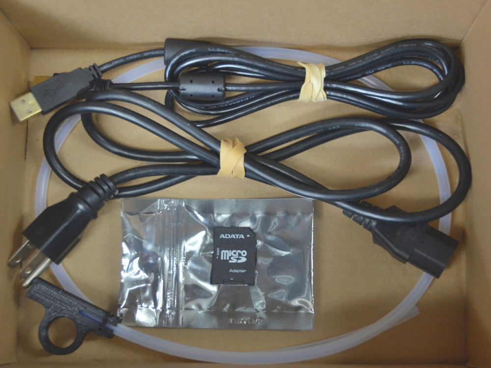
Coil the AC power cable and the USB cord and place inside the Accessory box
6A
If filament is loaded into the tool head, cut it free now, leaving no more than an inch above the tool head surface, remove and store in a dry place.
6B
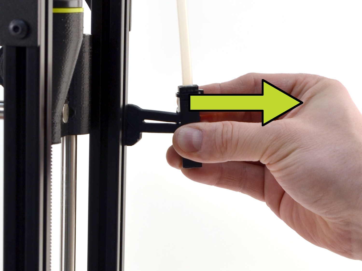
Remove the white plastic filament guide tube by sliding it off of the bracket.
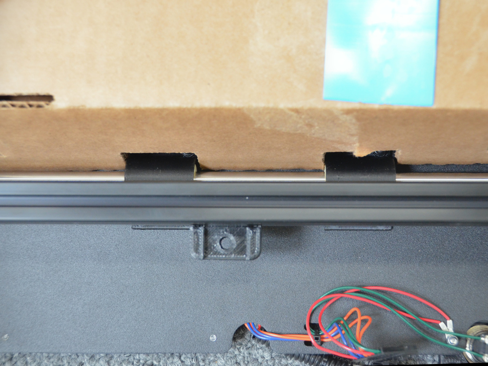
7A Lift and rotate the filament reel holder until it is stowed alongside the printer frame.
7B
Lift and rotate the filament guide tube bracket into the stowed position.
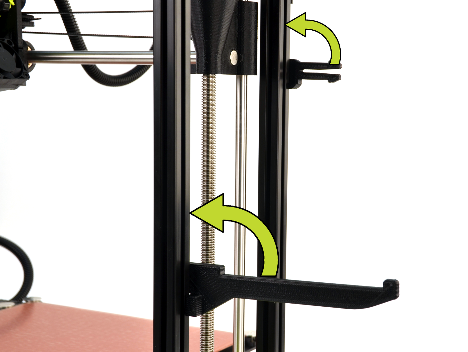
Use tape to secure the brackets.

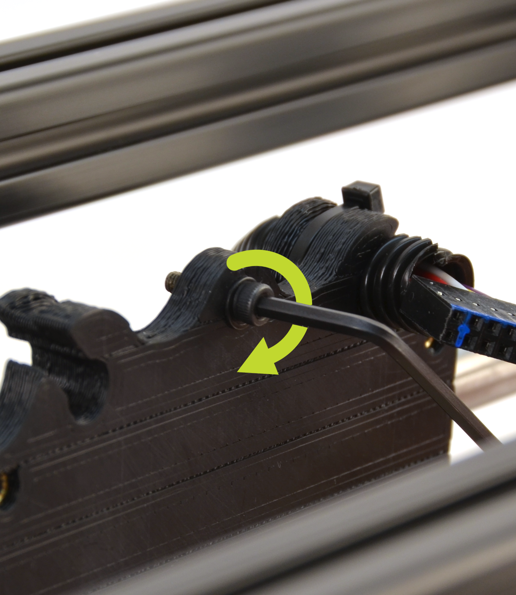
Unplug the tool head from the tool head harness, taking care to avoid bending or damaging any of the connector pins

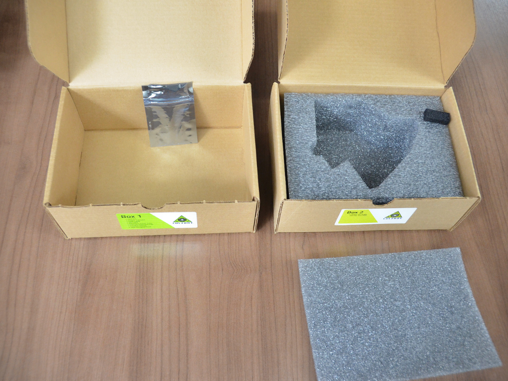
10A
Locate the small foam piece found in the Accessory box
10B
Press the small foam piece straight down onto the exposed tool head pins, taking care not to bend or damage them.

11A
Locate the tool kit and remove the 2.5 mm wrench.
11B
Note: Support the tool head with your hand to prevent it from
falling onto the print surface.
11C
Unscrew the tool head mounting screw by turning counter-clockwise from the X-axis carriage
with the included 2.5mm hex key.


12A
Place the tool head upside down into the tool head box.
12B
Make sure that the wiring is placed within the foam cutout.
12C
Set the tool head box aside.

13A
Screw in the tool head mounting screw back into the X-axis carriage
13B
Using your hand, move the X-axis carriage over to the far right-hand side of the printer.
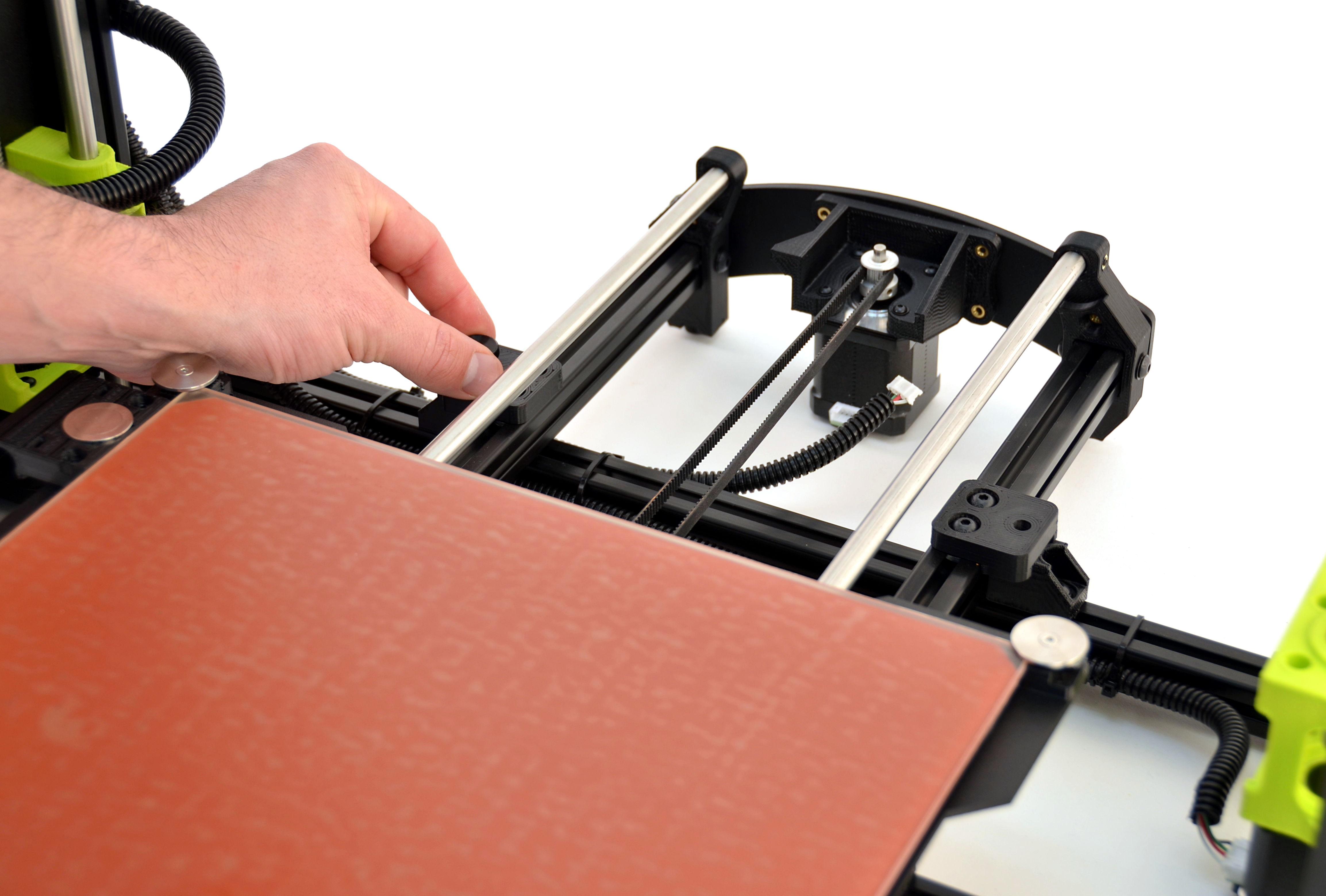
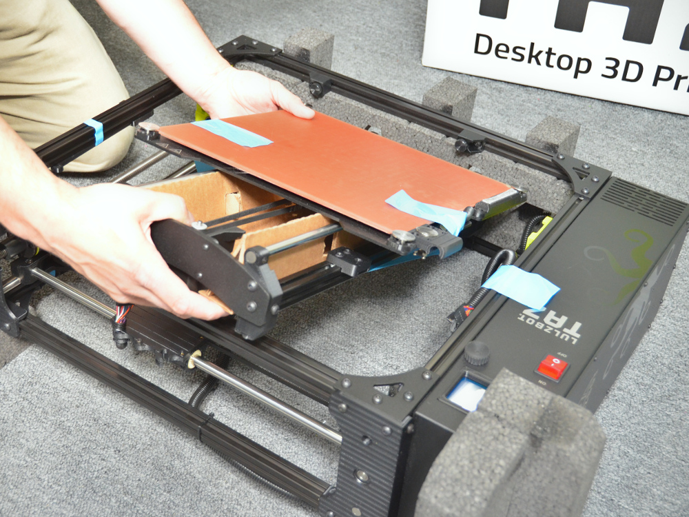
14A Slide the print surface towards you.
14B
Press down on the print surface cable, freeing it from the black cable mount.

Push on the locking tab to release the connectors and unplug each one. The thicker connector does not have a locking tab.

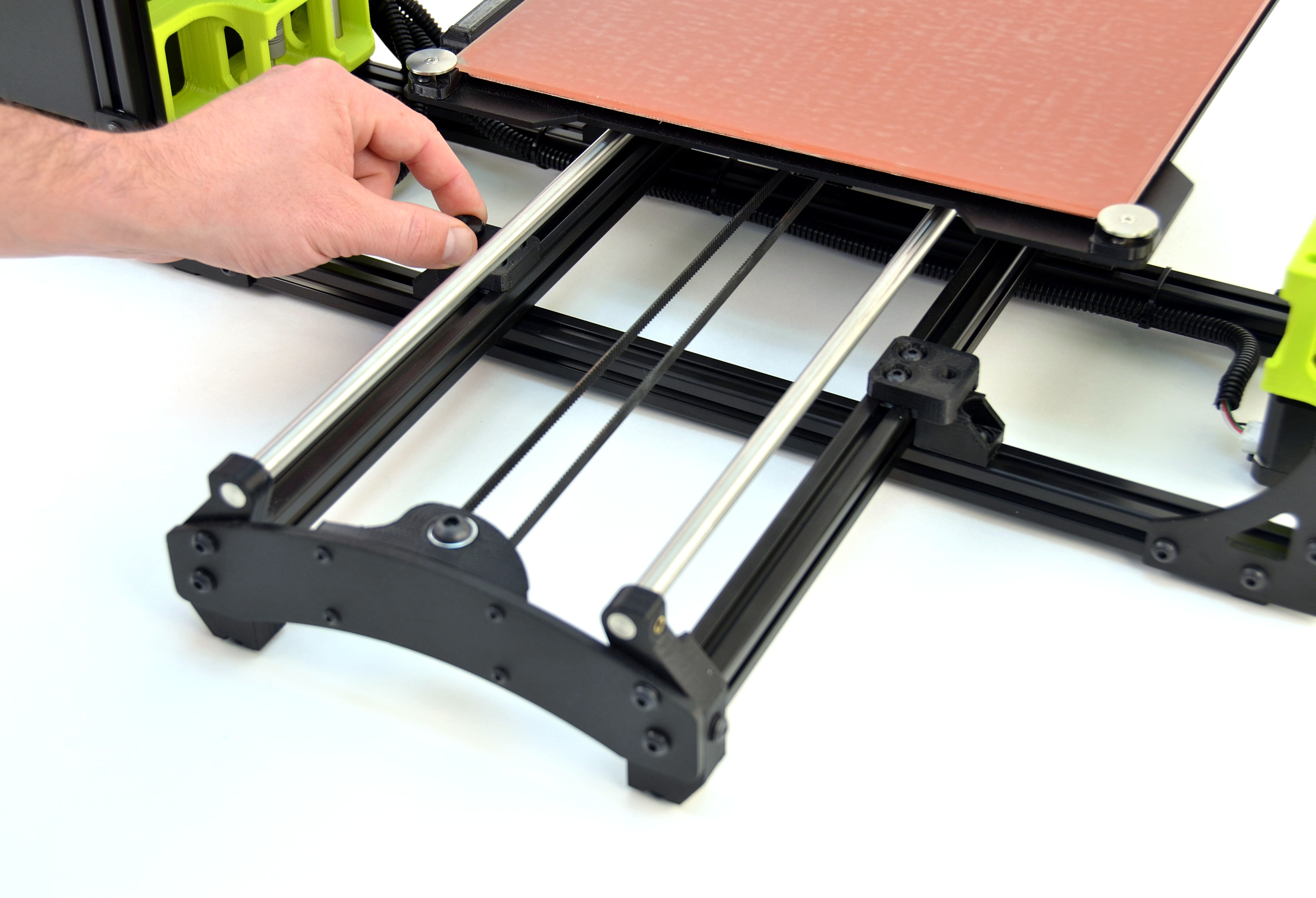
16A
Move the print surface all the way towards you, exposing the Y-axis stepper motor.
16B
Unplug the Y-axis stepper motor wire bundle by gently pulling straight away from the stepper motor.

17A
Remove the two (2) rear thumbscrews.
17B
Gently slide the print surface away from you, towards the rear of the 3D printer.
17C
Remove the two (2) front thumbscrews.
Tip: Need a place to temporarily hold the thumbscrews? Use the two small holes in each Z-axis stepper motor mounts!
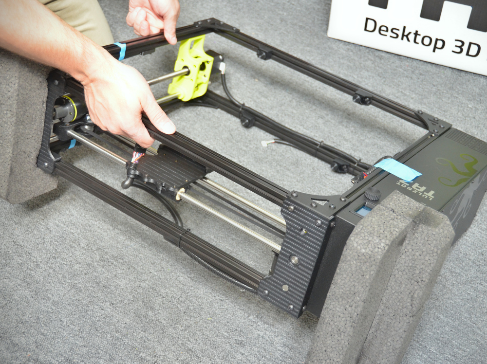
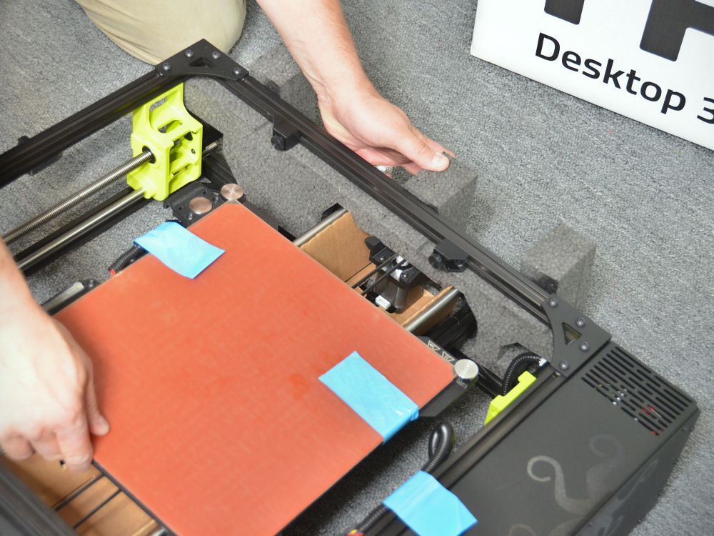
18A
Gently grab the Y-axis assembly by the two black metal endplates.
18B
Lift the Y-axis assembly straight up, away from the printer frame and set aside.

Screw the four (4) thumbscrews back into the middle of the 3D printer frame.

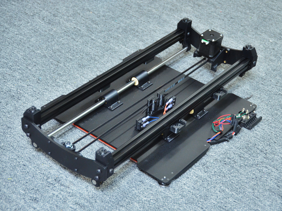
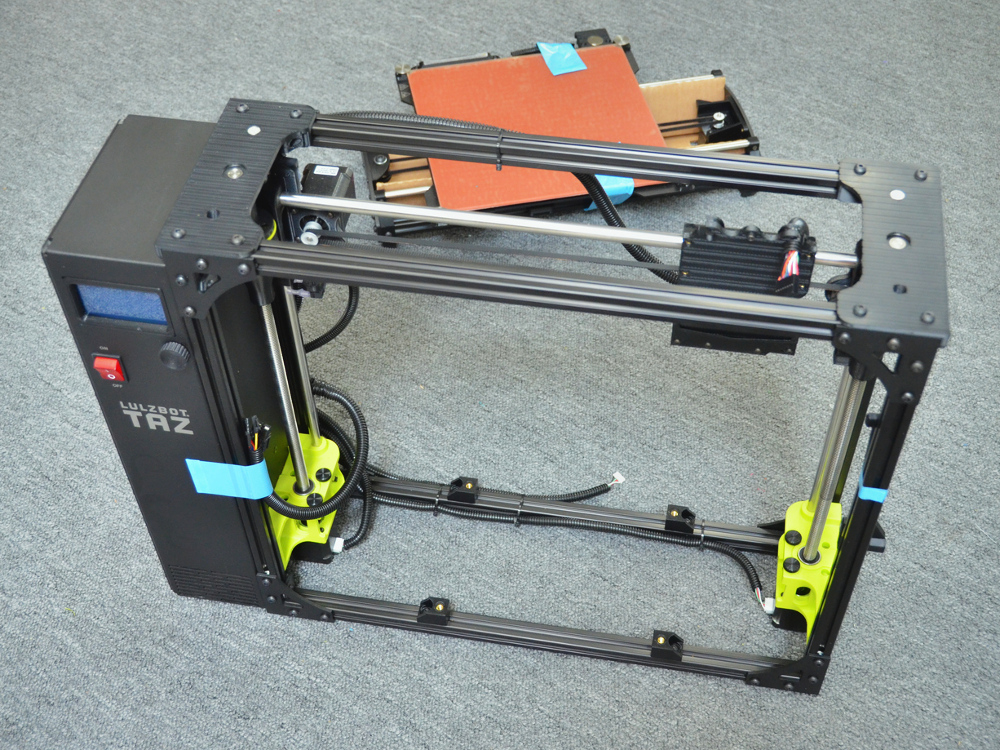
20A
Lift and rotate the Y-axis assembly so the print surface is facing down.
20B
Gently place the Y-axis assembly down onto the print surface.
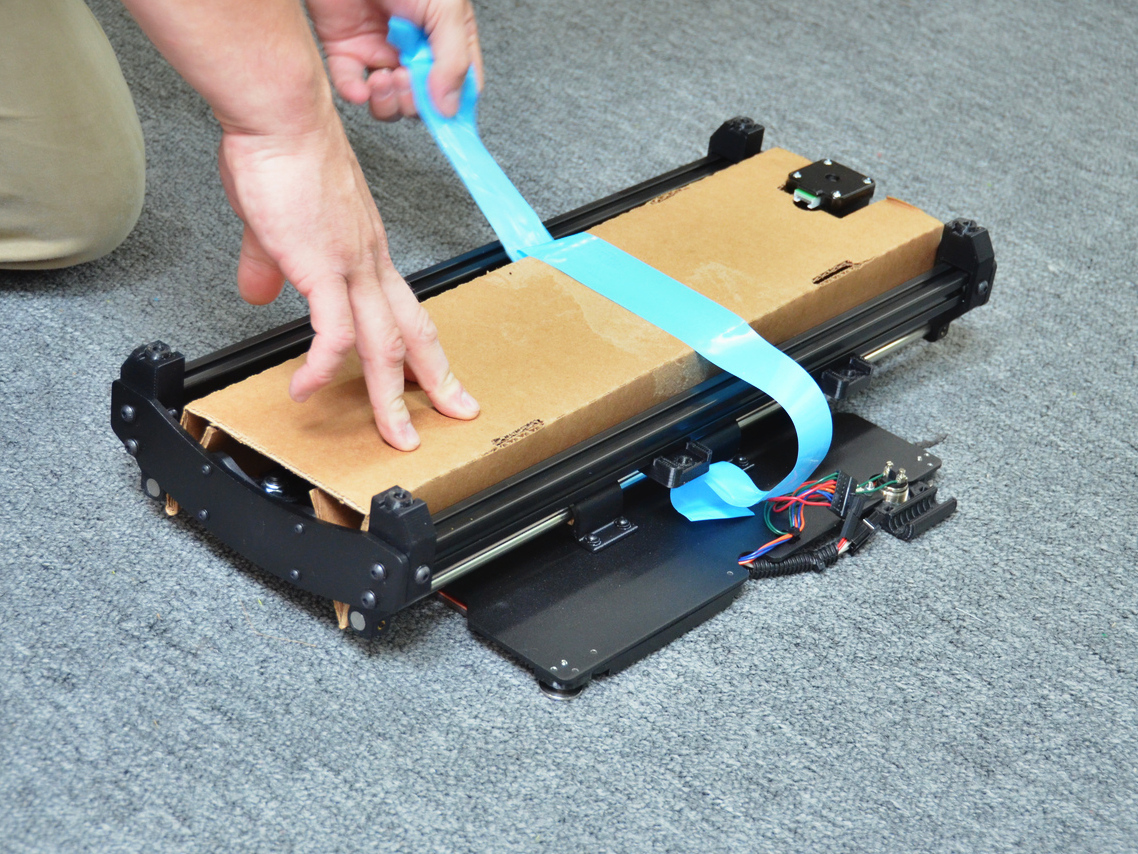
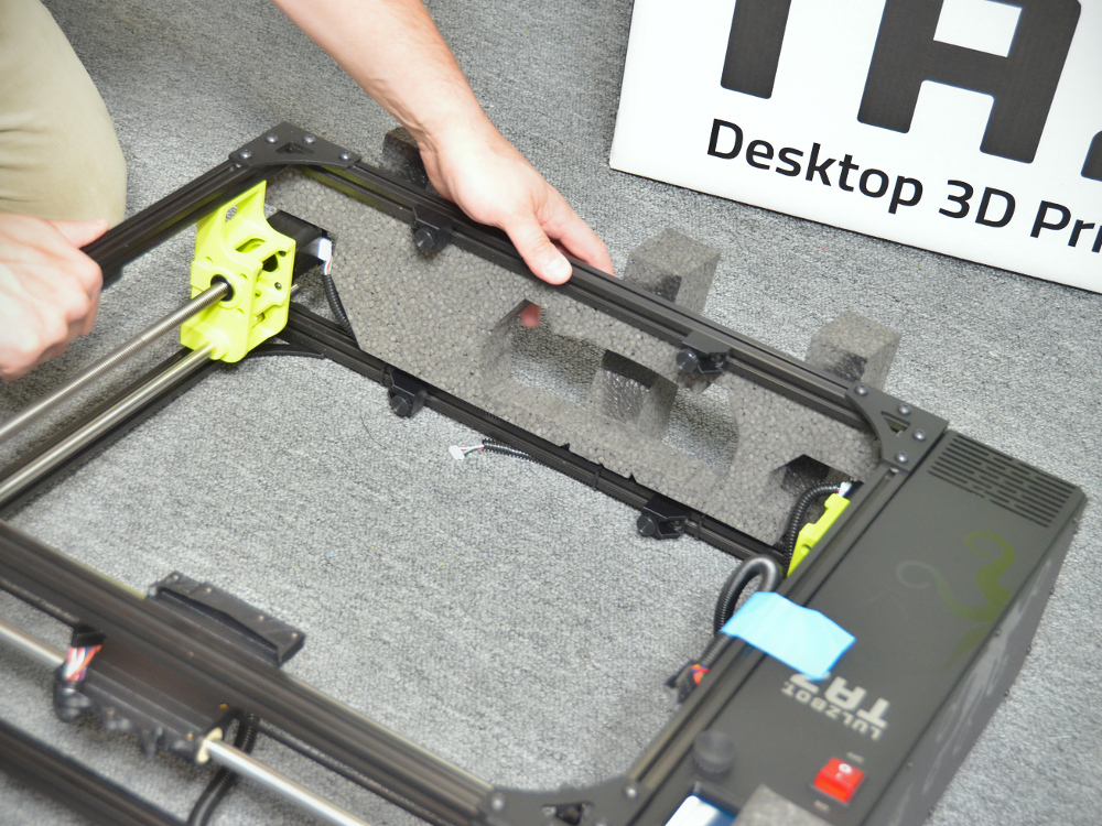
21A
Locate the Y-axis cardboard fixture.
21B
Slide the Y-axis frame until the print surface is near the middle of the Y-axis.
21C Fold and insert the cardboard fixture into the y-axis frame, aligning the cutouts.
Note: Look for the large stepper motor-sized cutout on one end of the cardboard fixture.
21D
Secure the fixture to the y-axis frame with tape.
22A
Move the main 3D printer frame onto a soft surface, leaving it standing up.
22B
Rotate the 3D printer frame around to face the rear of the 3D printer.
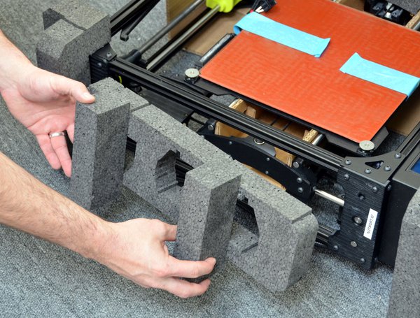
Note: There are four (4) corner foam braces. Three (3) are identical while one is larger.
23A
Locate the largest corner foam brace.
23B
With the largest side up, place the large corner foam brace onto the control box corner.

24A
Locate one corner foam brace
24B
Place the corner foam brace onto the other top corner of the printer frame.

25A
Lay the printer down, with the Graphical LCD controller and LulzBot TAZ logo up.
25B
Reposition the top foam braces if needed.
26A
Locate the bottom foam brace. Tip: The bottom foam brace is the longest of them all.
26B
With the long, thin side pointed into the printer frame, slide the bottom foam brace alongside the Z axis stepper motor and into the printer frame, from the outside, in.
26C
Place the TAZ 3D printer box on its side, behind the bottom of the printer frame.
27A
Place the Y-axis assembly, stepper motor-side first, into the main part of the printer frame and into the matching cutouts on the bottom foam brace.
27B
Lower the front of the Y-axis assembly into the printer frame.
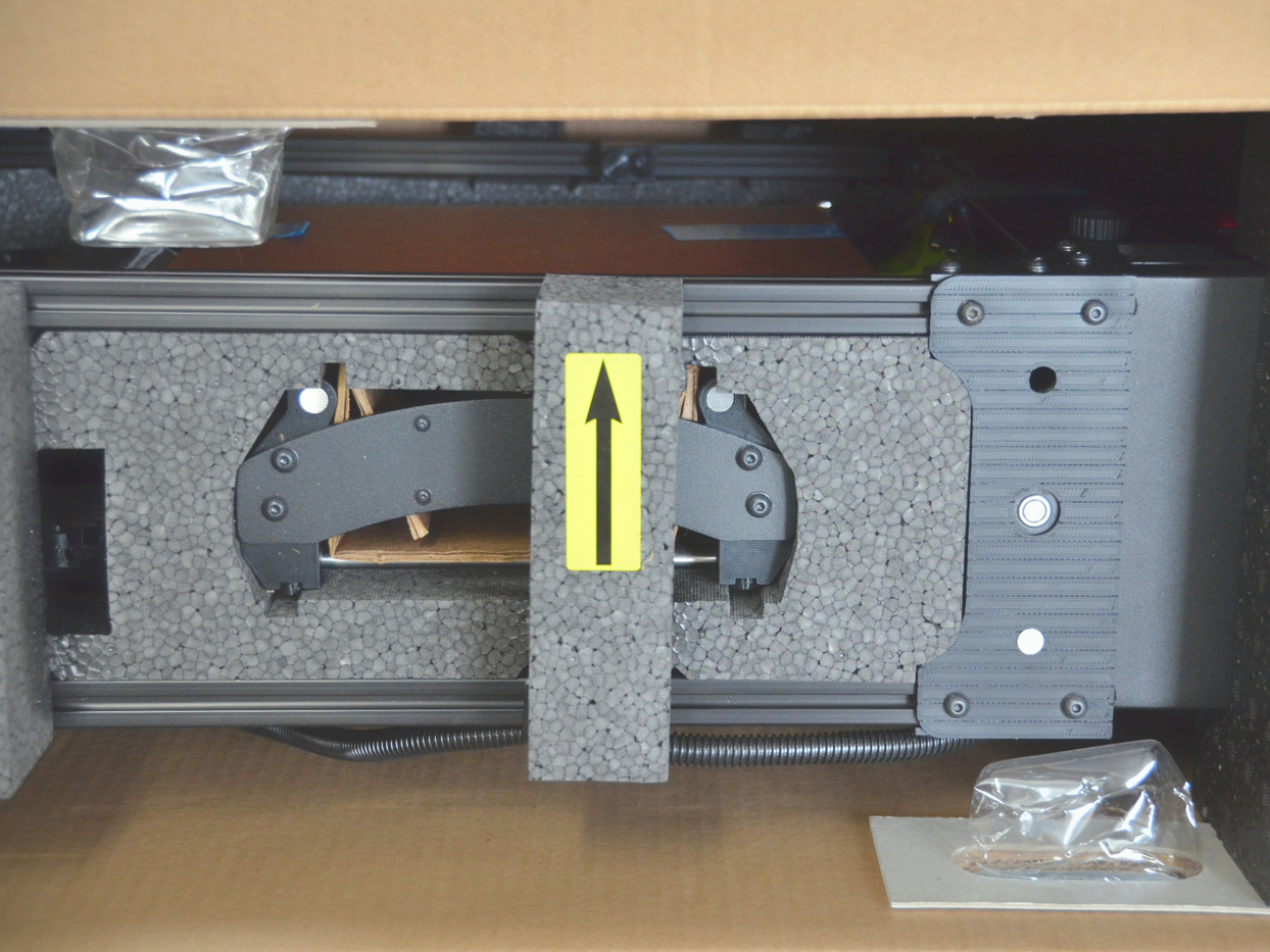
28A
Locate the oval-shaped top foam brace
28B
With the arrow up, gently press the top foam brace into the printer frame, taking care to align the Y-axis end into the foam cutouts.

29A
Locate the last two corner foam braces.
29B
Place the last two corner foam braces onto the bottom of the 3D printer frame.

30A
Slide the printer into the box.
30B
Re-position any corner foam braces if needed.
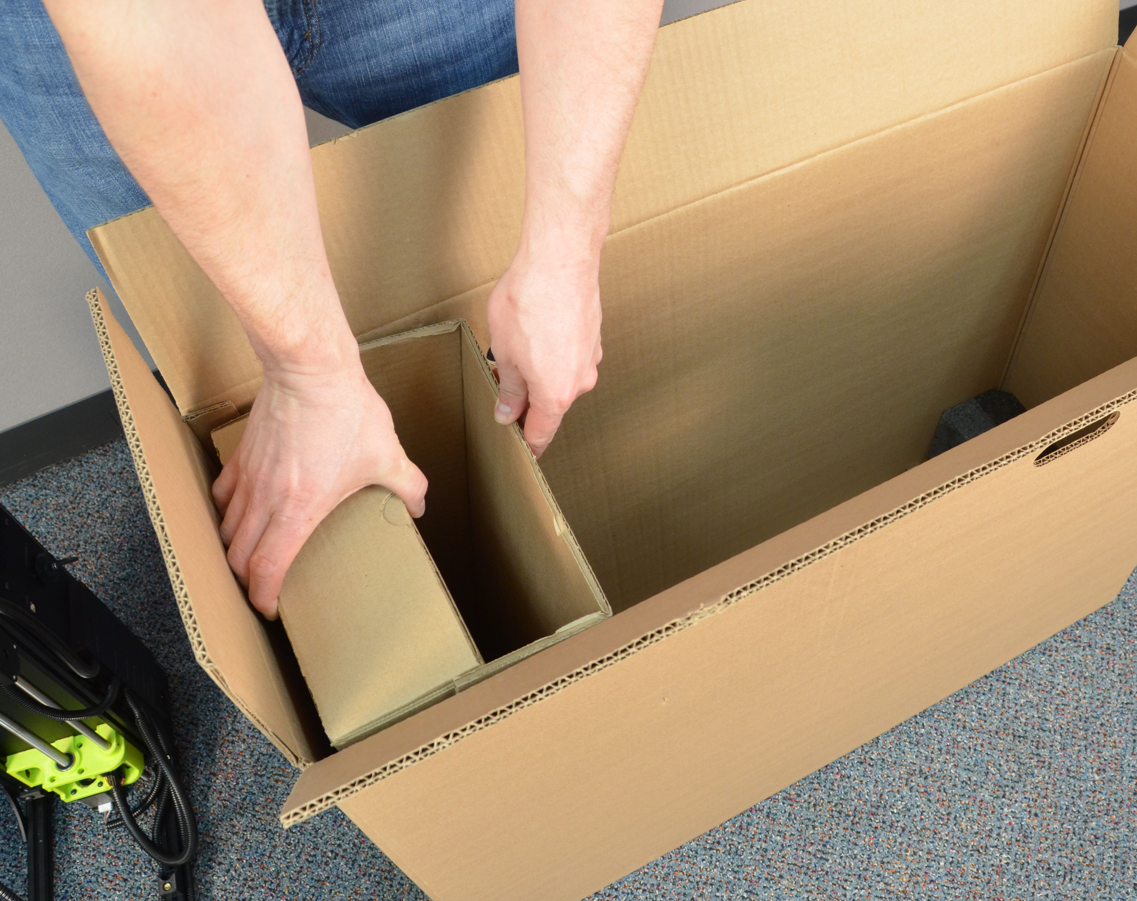
Tip: The cardboard divider is removable if needed. Do not discard. Re-install the cardboard divider and spacer if removed.

31A
Before continuing verify that the printer is seated within the box evenly.
31B
The cardboard divider should be evenly positioned alongside the printer as well.
Lift and rotate the TAZ printer box upright.
33A
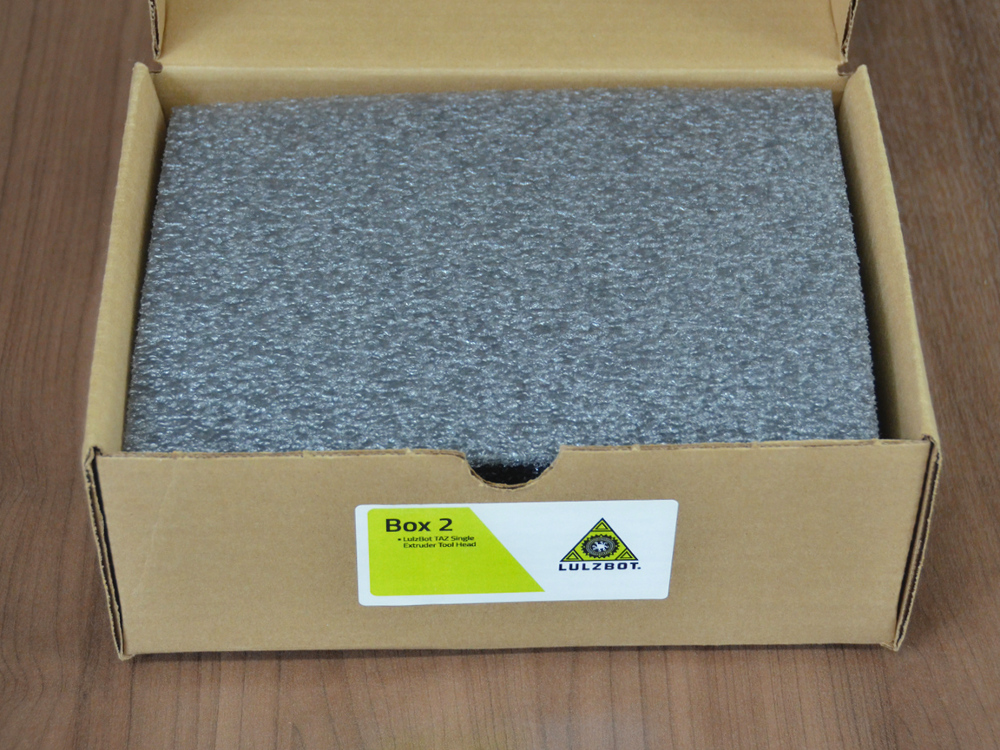
Before continuing, verify the contents of the Tool Head and Accessory box.
33B
Tool Head Box
Accessory Box

34A
Place the Tool Head Box into the TAZ 3D printer box. Slide the box all the way to the bottom.
34B
Place the Accessory Box into the printer box. The box should sit flush or below the top of the packaging.
34C
Use strong packing tape to secure the box flaps and edges.
Your TAZ 3D printer is now packed and ready to accompany you to your next creative outing!
It's a good idea to use a shipping service that offers tracking information and insurance.
Note: Are you shipping your printer in for service?
Aleph Objects cannot accept any item(s) back for repair, refund, or evaluation without an assigned RMA number provided by the Aleph Objects Technical Support Team. Any item(s) received without an RMA number will be returned to sender. Email Support@LulzBot.com for all return/repair inquiries.
