Open HardwareAssembly Instructions
Guides for installation and assembly of the LulzBot line of products made by Aleph Objects, Inc.
Guides for installation and assembly of the LulzBot line of products made by Aleph Objects, Inc.
This guide uses Cura: LulzBot Edition for both slicing the 3D model and for controlling your LulzBot 3D printer. Download and install Cura by following the instructions found at LulzBot.com/Cura.
Download the following files by selecting the files below or by right clicking and selecting Save link as:
Additional items required:
Additional items recommended:
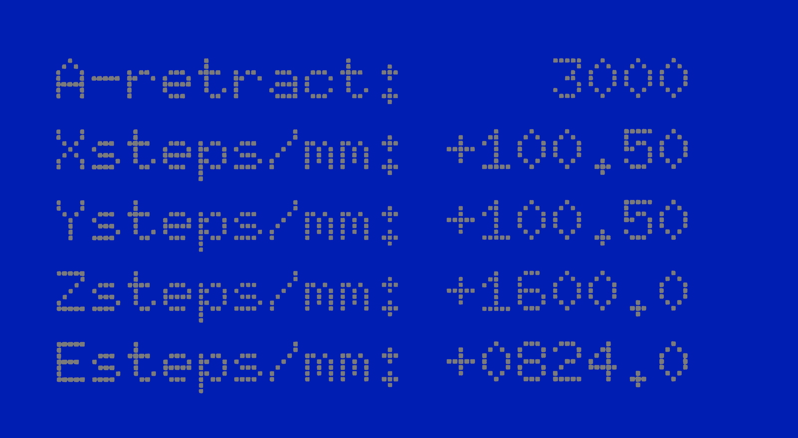
Record your current ESTEPS by using your Graphical LCD controller. Navigate to:
Configuration > Advanced Settings > scroll down to Esteps/mm and E1stps/mm and record both Esteps values.
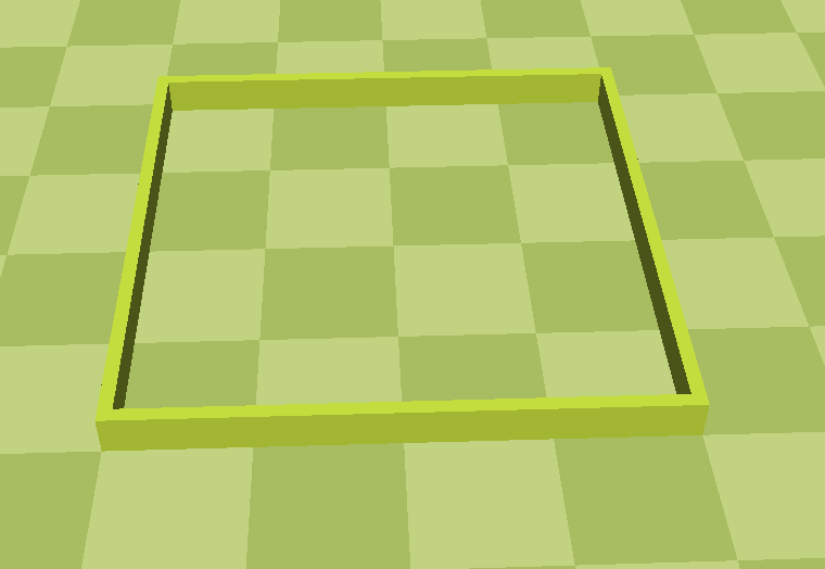
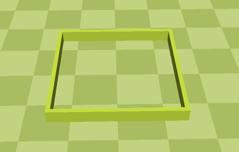
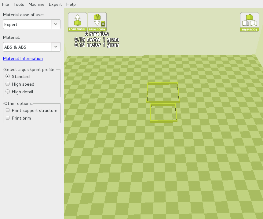
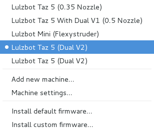
Open Cura and select your LulzBot TAZ 5 (Dual v2) machine profile by selecting Machine > LulzBot TAZ 5 (Dual v2). Load the outer_square.stl and inner_square.stl 3D models into Cura.
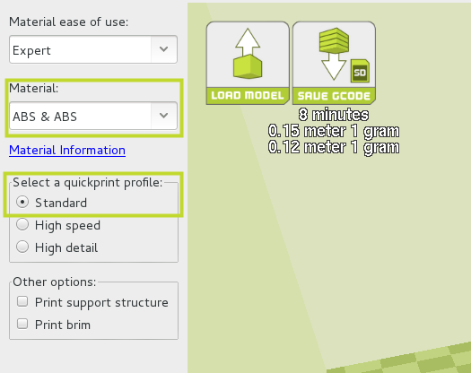
In Cura, under Material select:
ABS + ABS
Under quickprint profile select Standard
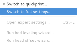
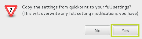
Switch modes by selecting:
In the new window that opens, select Yes to copy over the profile settings.
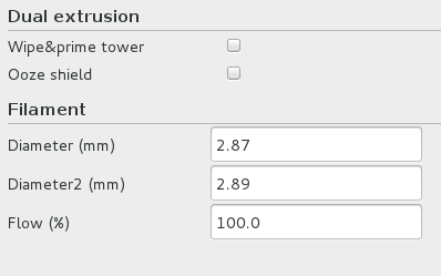
Using your digital calipers measure and record the filament diameter of both filament reels. We recommend measuring across several meters using the flat portion of the calipers. Average your results and update the measured average filament diameter in the Basic tab under Filament:
Since we are only concerned with calibrating our Dual Extruder Tool Head v2, we can turn off some options to achieve a quicker print. In the Basic tab under Dual Extrusion, turn off:
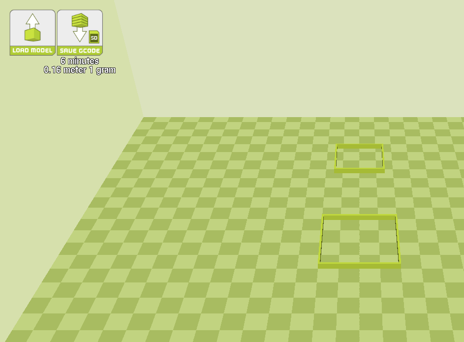
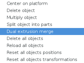
With the outer and inner square on your build platform, right click anywhere on the build platform and select Dual Extrusion Merge. The models will merge together. The red square will be printed with your front extruder, and the yellow square will be printed with the rear extruder.
Make sure that your LulzBot TAZ 3D printer is powered on and connected to your computer using a USB cable.
Press the Control button to open the Control Window / Printer Interface. You may need to wait a few seconds for the Save GCODE button to change to the Control button.
The title bar of the printer interface window will display the current status. As Cura connects to your 3D printer it will switch from Connecting to Operational.
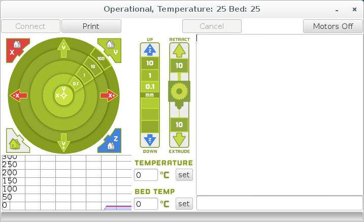
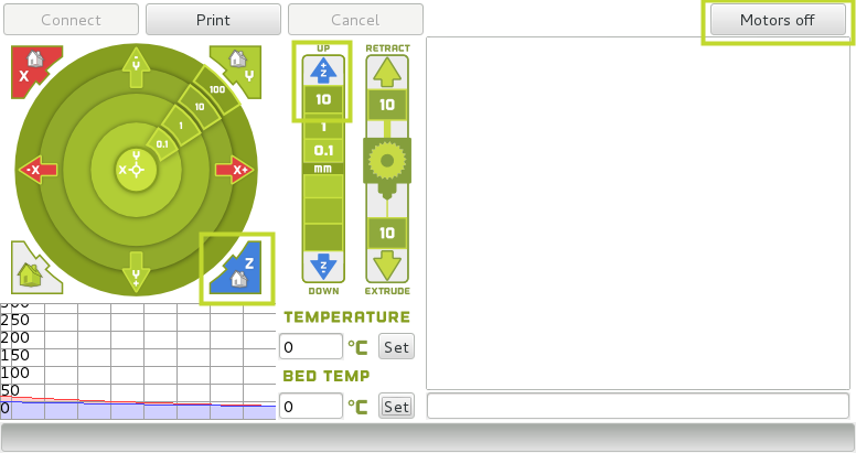
The hot end needs to be raised above the print surface. Press the Home Z button to home the printer. Move the Z axis up 30 or 40 mm off the print surface by pressing the Up 10 button. We need room underneath the hot end for the manual extrusions in the next few steps.
Press Motors Off and move the print head to the center of the bed by hand.
Use the terminal entry box in the lower right hand side of the control window to manually enter the GCODE commands. Replace any S_ _ _ value with your specific filament extrusion temperature if you are using a filament other than ABS.
Set Extruder 0 (rear) as the active extruder:
T0
Press Enter on your keyboard to send the command.
Set Extruder 0 (rear) hot end to extrusion temperature:
M104 S240
Set extruder 1 (front) hot end as the active extruder:
T1
Set Extruder 1 (front) hot end to extrusion temperature:
M104 S240
Set print surface temperature:
M140 S110
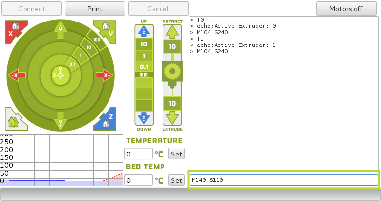
Make two marks on the filament at 100 mm and 120 mm from the top surface of each extruder. A permanent marker works well for this purpose.
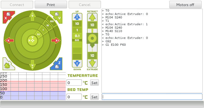
Once each hot end has reached its extrusion temperature type in the following commands into the lower right hand portion of the Cura control window:
Set Extruder 0 (rear) as the active extruder:
T0
Set X, Y and Z axis coordinates to zero:
G92
Move active extruder axis to pull in 100mm of filament into Extruder 0
G1 E100 F60
The printer will pull in 100 mm of filament into the extruder. It does not matter what happens to the filament that is extruded.
Measure the distance the filament traveled on Extruder 0 (rear). For every mm the filament over extruded subtract 8 Esteps from your current value. For every mm the filament under traveled, add 8 Esteps to your current value.
Update your Extruder 0 Esteps through your Graphical LCD controller. Navigate to: Configuration > Advanced Settings > Scroll down and select Esteps/mm. Use the control knob on the Graphical LCD controller to adjust the value. Once set, back out of the menu entries until you can select Store Memory.
Select Store Memory to save the adjusted Extruder 0 Esteps/mm.
Check to see if the changed Esteps have improved the filament travel accuracy. Make two marks on the filament at 100 mm and 120 mm from the top surface of Extruder 0 (rear).
Set Extruder 0 (rear) as the active extruder:
T0
Set X, Y and Z axis coordinates to zero:
G92
Move active extruder axis to pull in 100mm of filament into Extruder 0 (rear)
G1 E100 F60
The printer will pull in 100 mm of filament into the extruder. Once Extruder 0 (rear) stops moving, measure the filament travel distance. If needed, repeat the previous 5 steps until you are satisfied with the new updated Esteps. Calibrate Extruder 1 (front) next.

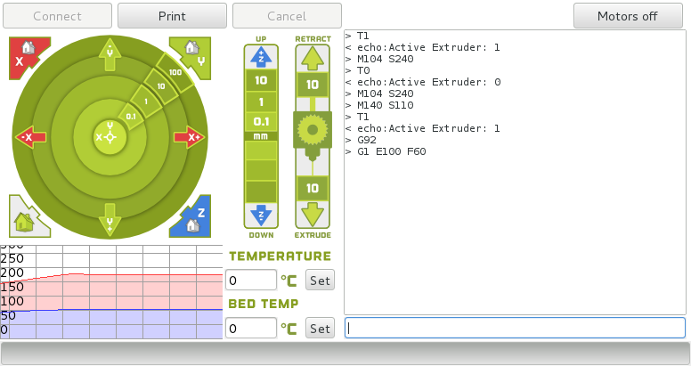
Set Extruder 1 (front) as the active extruder:
T1
Set X, Y and Z axis coordinates to zero:
G92
Move active extruder axis to pull in 100mm of filament into Extruder 1 (front)
G1 E100 F60
The printer will pull in 100 mm of filament into the extruder. It does not matter what happens to the filament that is extruded.
Measure the distance the filament traveled on Extruder 1 (front). For every mm the filament over extruded subtract 8 Esteps from your current value. For every mm the filament under traveled, add 8 Esteps to your current value.
Update your Extruder 1 Esteps through your Graphical LCD controller. Navigate to: Configuration > Advanced Settings > Scroll down and select E1stps/mm. Use the control knob on the Graphical LCD controller to adjust the value. Once set, back out of the menu entries until you can select Store Memory.
Select Store Memory to save the adjusted Extruder 1 Esteps/mm.
Check to see if the changed Esteps have improved the filament travel accuracy. Make two marks on the filament at 100 mm and 120 mm from the top surface of Extruder 1 (front).
Set Extruder 1 (rear) as the active extruder:
T1
Set X, Y and Z axis coordinates to zero:
G92
Move active extruder axis to pull in 100mm of filament into Extruder 1 (front)
G1 E100 F60
The printer will pull in 100 mm of filament into the extruder. Once Extruder 0 (rear) stops moving, measure the filament travel distance. If needed, repeat the previous 5 steps until you are satisfied with the new updated Esteps. Leave the Control window open.
To determine the X and Y axis postioning adjustments needed, print the inner and outer square now.
Make sure that both hot ends are at the proper extrusion temperature and that the print surface is at its ideal temperature as well.
Press Print to print the merged Calibration Squares model.
As your 3D printer moves to print each portion it will switch between active extruders automatically. Monitor the print progress for it should only take a few minutes. Once the print has finished proceed to the next step.

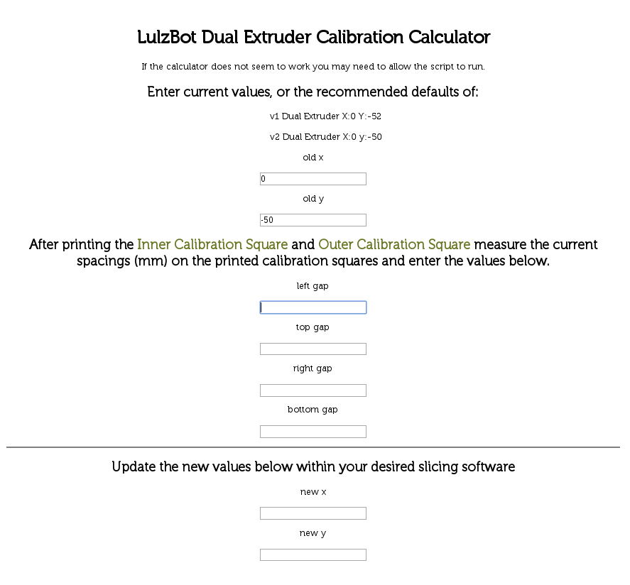
Once the printed objects are complete, leave them on the print surface. Use your digital calipers to measure the gap between each model from the top & bottom, and the gap between each side. Record your current values.
Enter these numbers into our offset calculator found here: https://www.lulzbot.com/dual-extruder-calibration-calculator
This will produce new offsets, that will need to be updated in the Machine Settings menu.
Close the control window.
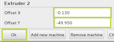
Open the Machine settings window by selecting:
Machine > Machine Settings
Update your__X__ and Y offsets and save the changes by pressing OK.
Reprint the inner and outer calibration squares using the steps in this guide to fine tune the offsets until you are satisfied with the results.
Once the printed objects are complete, leave them on the print surface. Use your digital calipers to measure the gap between each model from the top & bottom, and the gap between each side. Record your current values.
Once you are satisfied with the dual extruder offsets print a two color dice to celebrate! The model is available here:
Happy printing!