Open HardwareAssembly Instructions
Guides for installation and assembly of the LulzBot line of products made by Aleph Objects, Inc.
Guides for installation and assembly of the LulzBot line of products made by Aleph Objects, Inc.
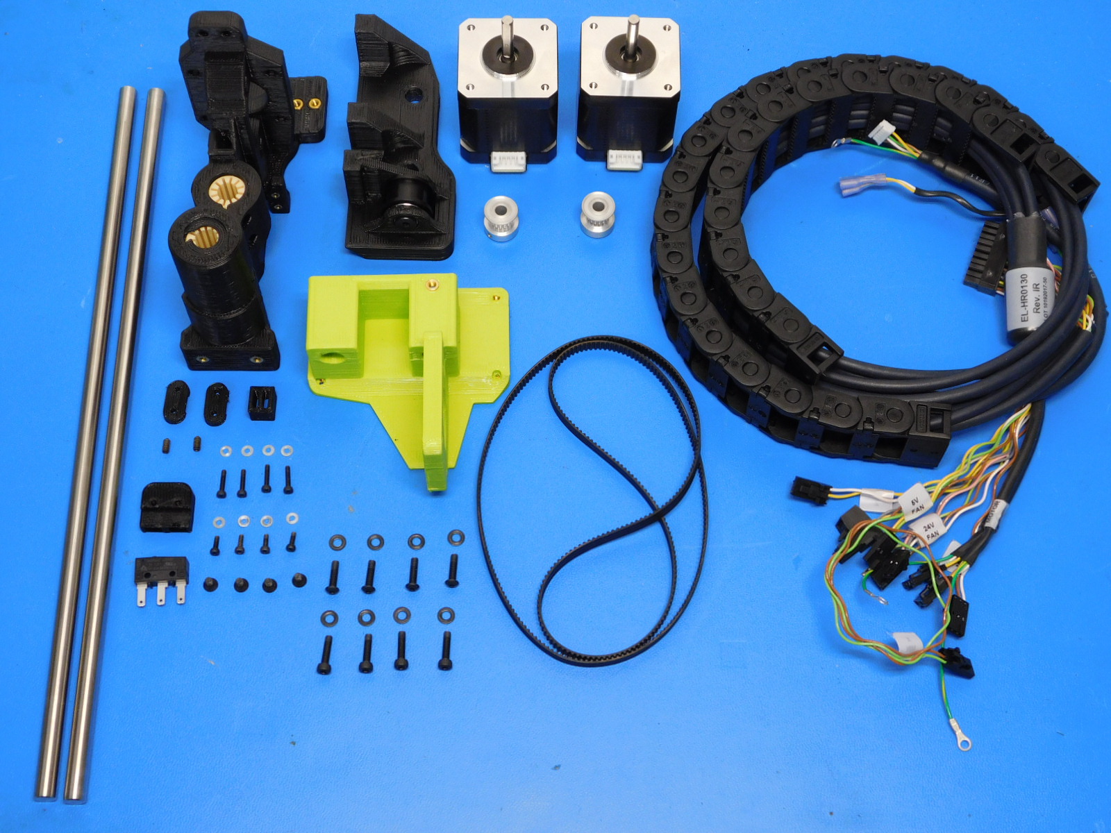
Materials required for AS-PR0099:
1x- [AS-PR0090] X end motor assembly with inserts and bushings, Mini 2
1x- [AS-PR0091] Z Upper Left Assembly, Mini 2
1x- [PP-GP0307] Belt Tensioning Collar
2x- [PP-GP0308] Z Belt Clamp
1x- [PP-GP0332] Bump Stop
1x- [PP-IS0049] Z Lower Left With Inserts, Mini 2
1x- [EL-HR0130] Mini X Extruder Harnesses Assembly - Rev IR
2x- [EL-MT0029] NEMA 17 Stepper Motor, Moons' - NOT INCLUDING wire harness
1x- [EL-SW0022] SWITCH BASIC SPDT 3A .110QC 125V
1x- [HD-BL0033] Timing belt, 372 teeth, GT3 2mm pitch, 744 mm pitch length, 6 mm belt width, Neoprene
2x- [HD-BT0012] M3 Set Screw (Grub Screw)
4x- [HD-BT0039] Socket Head Cap Screw M3 Thread, 12MM Length
4x- [HD-BT0107] Socket Head Cap Screw M2 Thread, 10mm Length
4x- [HD-BT0128] M3 x 6 Bolt, FHCS Black-Oxide
4x- [HD-BT0146] M3 x 12 BHCS, Black Oxide, Class 10.9 Steel
2x- [HD-MS0033] GT2, 16 Teeth, timing pulley
4x- [HD-MS0058] Wire Tie, 8" Black, pk 1000
4x- [HD-MS0230] Socket Head Cap Screw M2 Thread, 6mm Length
2x- [HD-RD0035] 8mm Smooth rod, 315mm, 300 Series Stainless Steel
8x- [HD-WA0012] Steel Flat Washer, M2 screw size, 5mm OD
8x- [HD-WA0038] Black-Oxide 18-8 Steel Flat Washer, M3 Screw Size, 3.2mm ID, 7.0mm OD
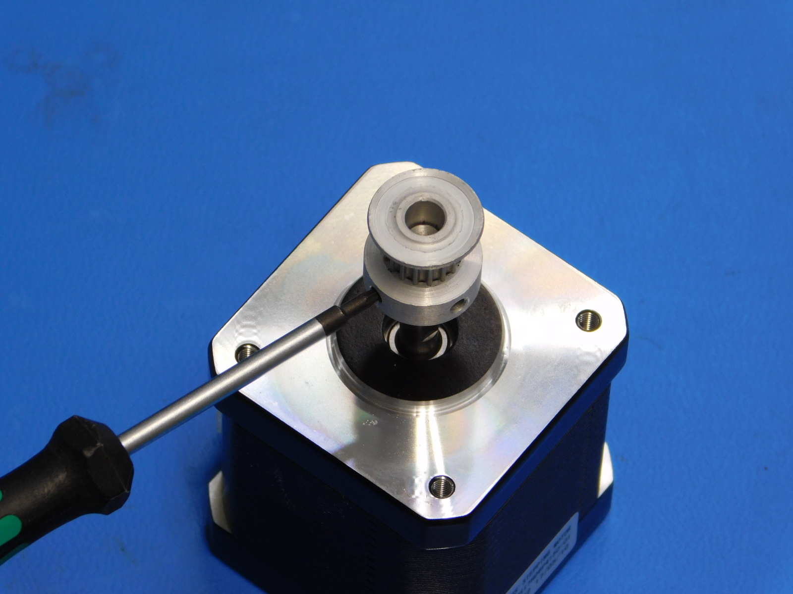
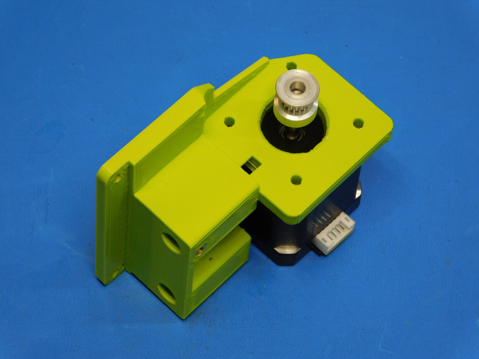
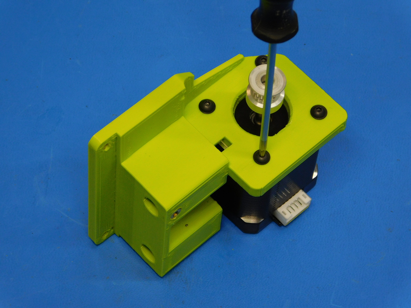
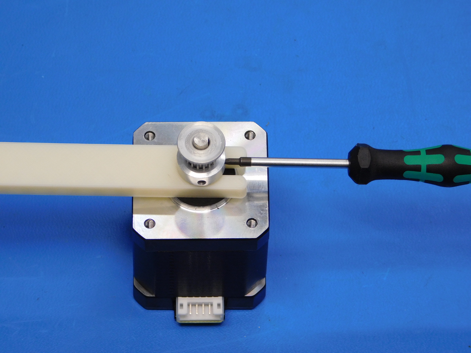
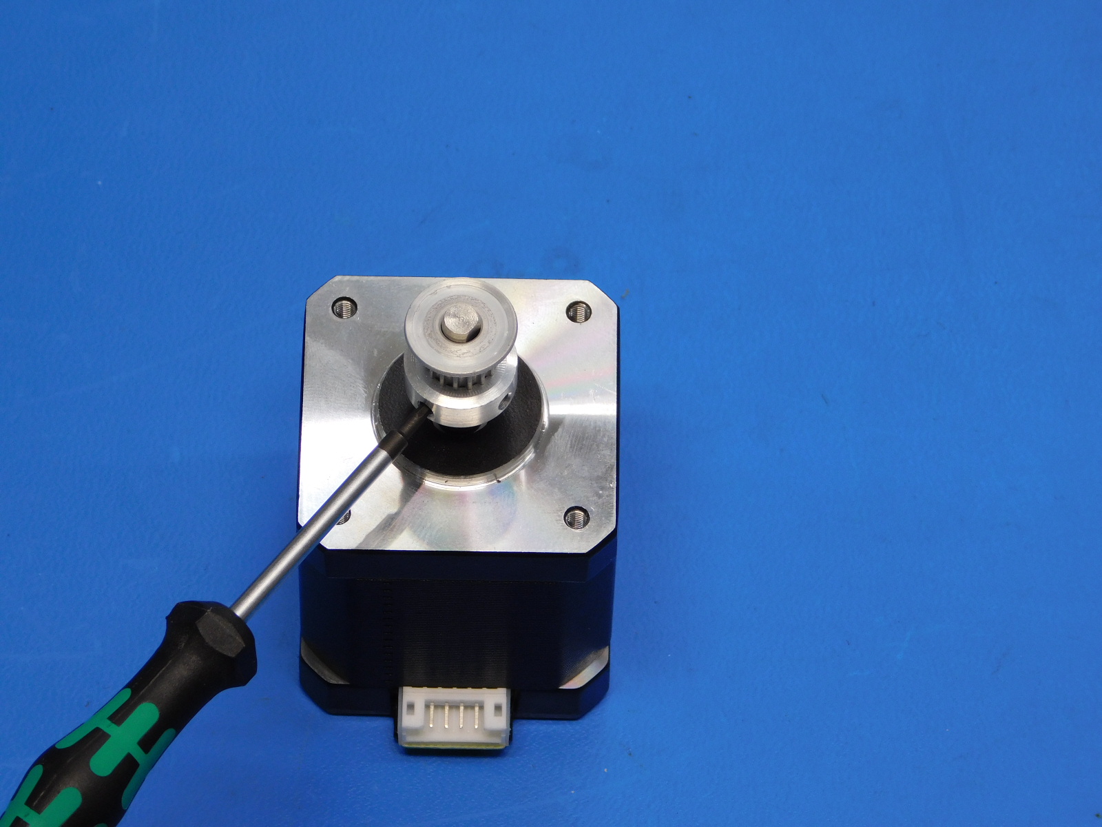
Attach a Pulley [HD-MS0033] to a Motor [EL-MT0029] offset the pulley from the face of the motor 13mm.
Ensure one of the pulley set screws is aligned with the flat segment of the motor shaft, secure pulley in place with the two set screws already installed in the pulley, tighten securely.
Align the Z-Motor with the Z-Lower Left (orientation is critical) the motor connector is to be facing toward the right of the Z lower left part.
Attach the motor to the Z lower left using 4x- M3x12 BHCS [HD-BT0146] with 4x- M3 washers [HD-WA0038] , tighten screws to 8 in*lbs.

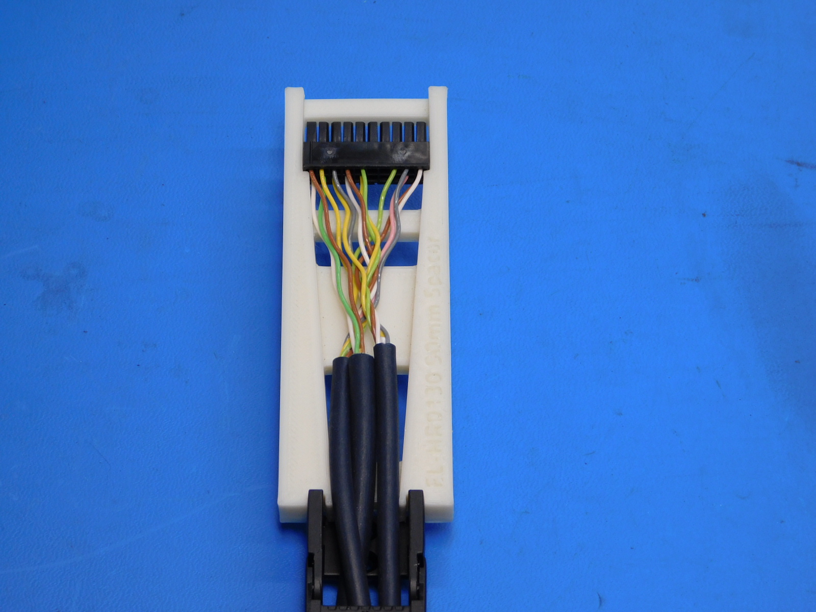
Set the 20 position connector at the Extruder end of the cable harness to 90 mm from the back of the connector to the end of the cable chain, using the printed jig. Secure the cable in place with a cable tie.
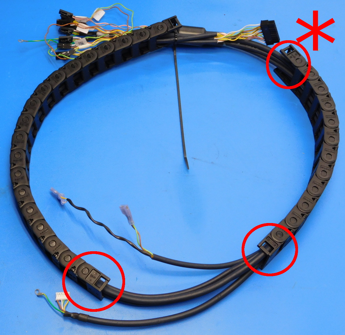
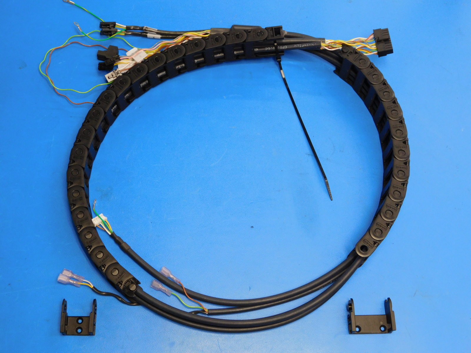
Remove the three highlighted cable chain mount ends See [reference#1]
Pass the female 30mm cable chain mount to the frame assembly workstation (highlighted with asterisk in [reference#1], located near the ferrite)
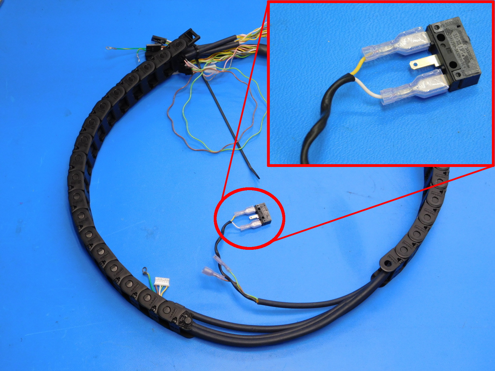
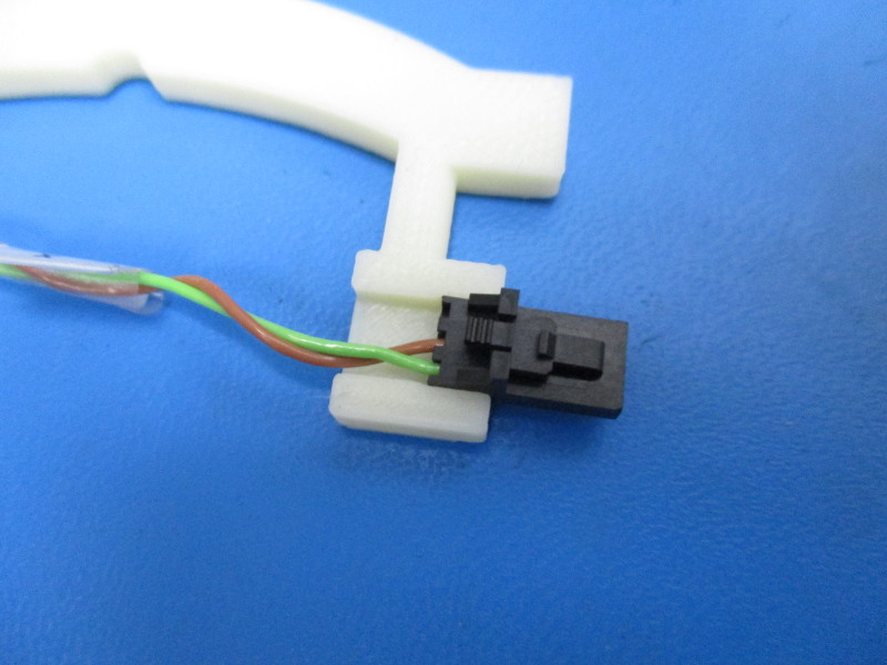
Connect Yellow & White wires to a end stop switch [EL-SW0022] see attached picture.
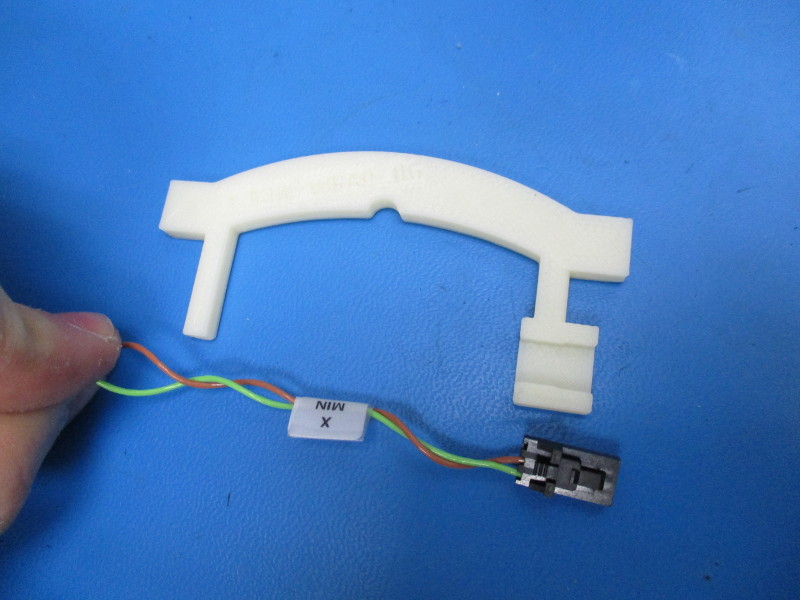
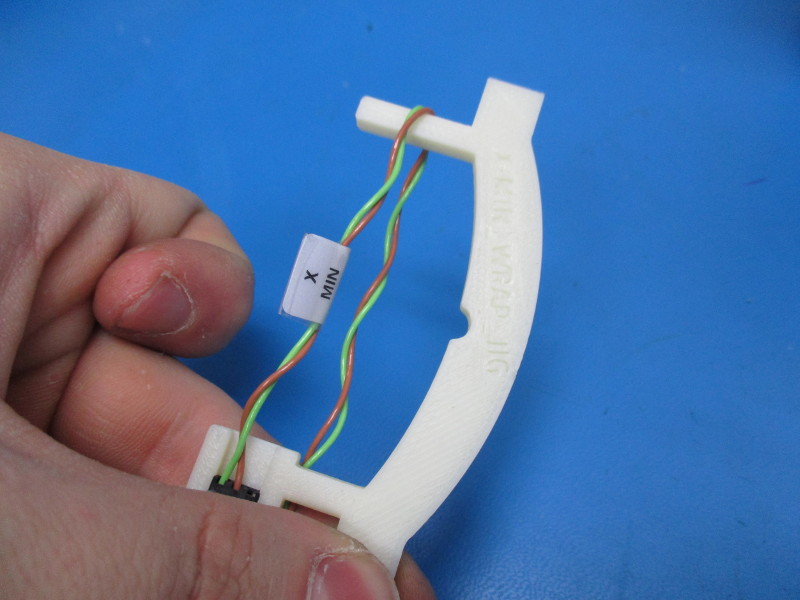
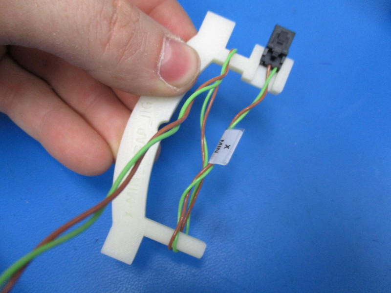
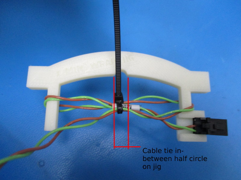
Wrap the wires labeled "X-Min" as follows: Snap the molex connector into the jig as shown. Wrap the wire around the far post on the jig and run the wire back to the post closest the molex housing. Wrap the wire around the post closest to the molex housing and run the wire back to the far post. Cable tie the center of the wrapped wires, designated by the half circle in the jig.
Attach the 20mm cable chain mount to the X-End Motor part (Motor mount side), use 2x M3x 6 FHCS [HD-BT0128] black oxide screw, tighten to 5 in*lbs.
Attach the 30mm cable chain mount to the X-End Motor part (Drylin bearing side), use 2x M3x 6 FHCS [HD-BT0128] black oxide screw, tighten to 5 in*lbs.
Align and install the Bump Stop with the mount located in the middle of the X-End Motor part as pictured. The Bump Stop should be oriented with the flat side facing away from the belt path. Secure the Bump Stop with 2x- M2x10 SHCS [HD-BT0107] with M2 washers [HD-WA0012], tighten screws until the Bump Stop no longer moves freely.
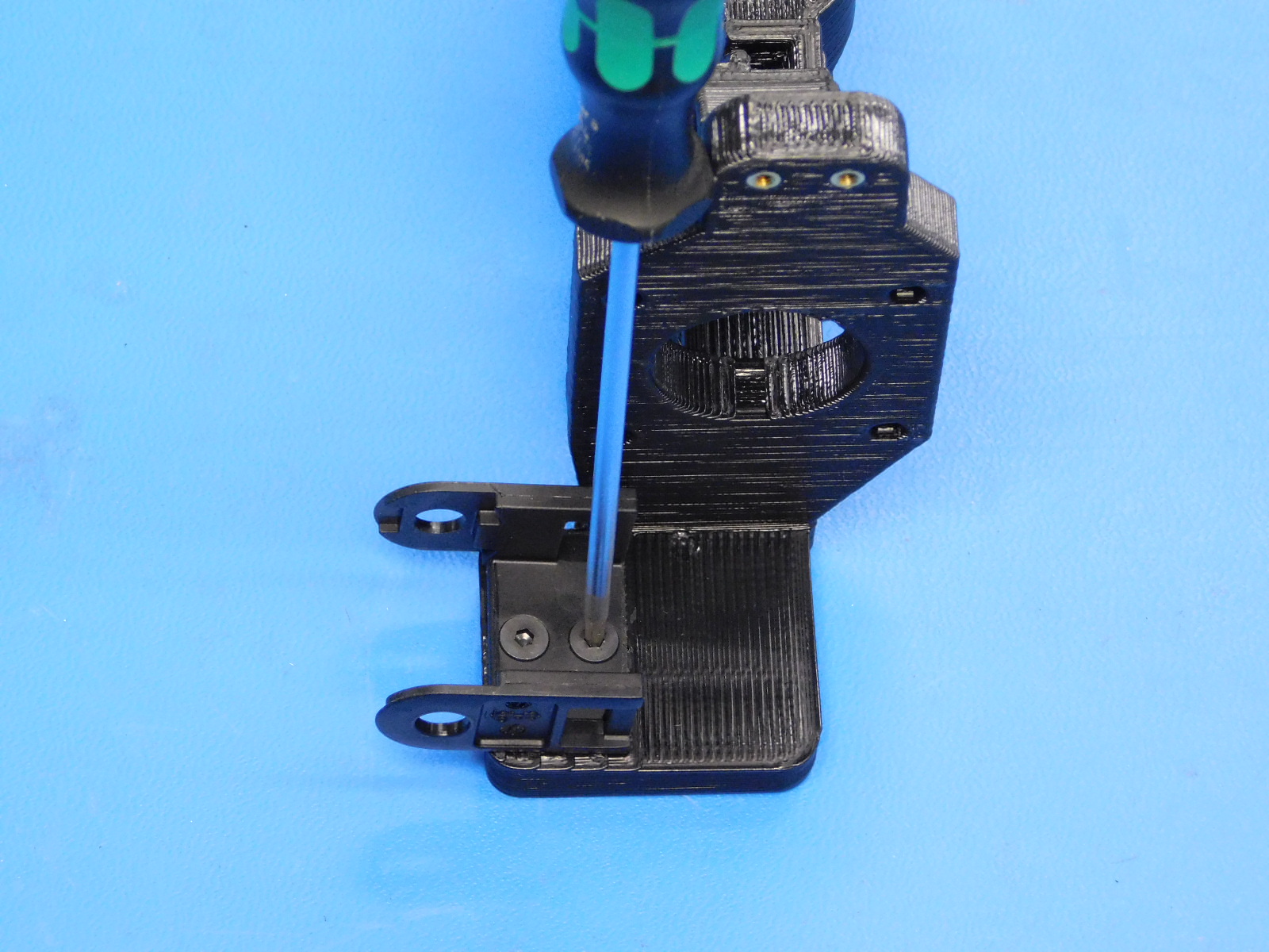
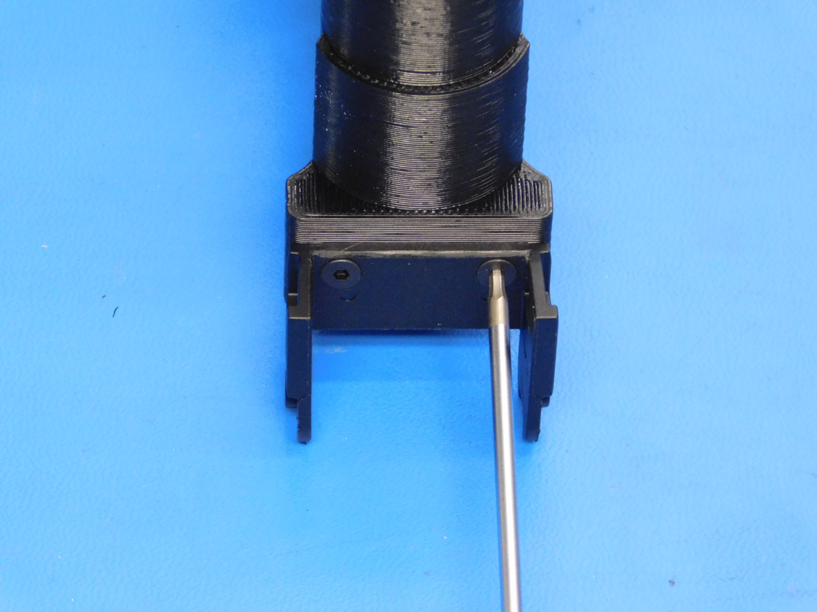
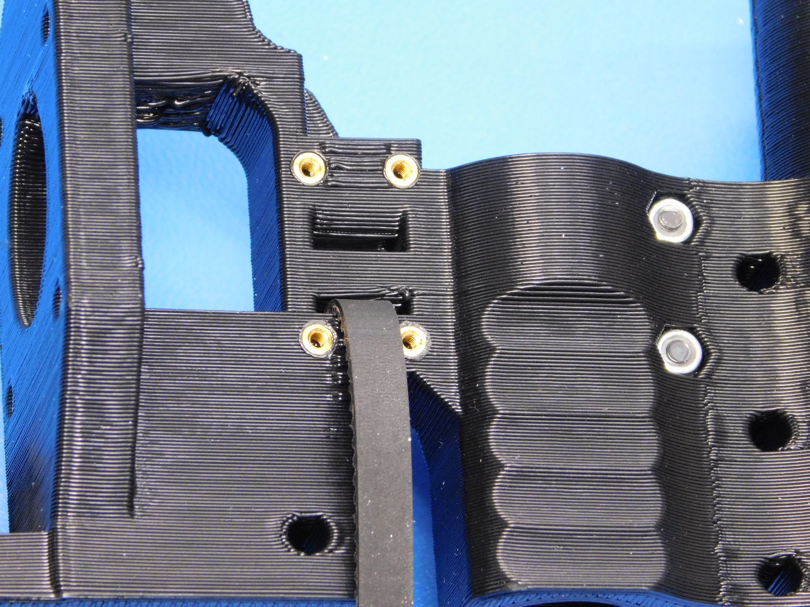
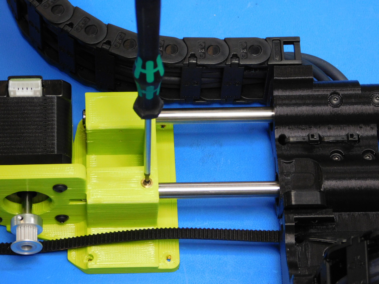
Cut a belt [HD-BL0033] straight with the the teeth of the belt and insert one end into the lower slot of the Z-Belt clamp feature. [reference#2]
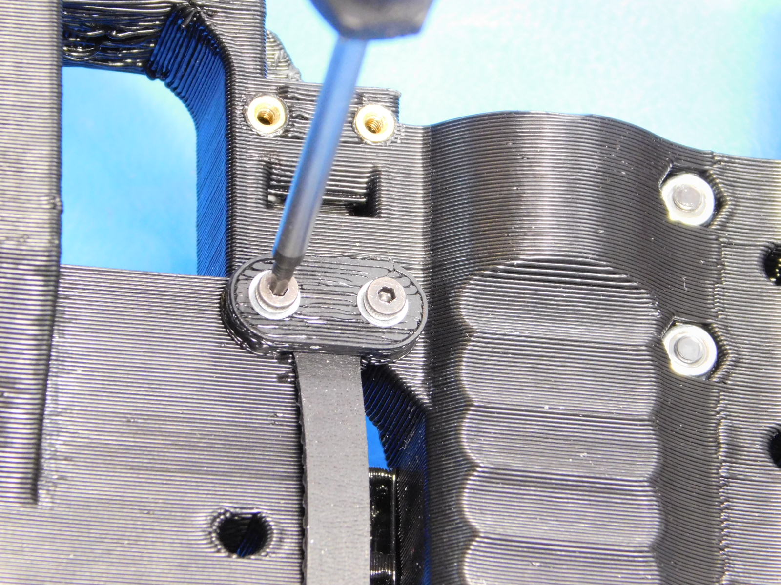
Clamp the belt in place using one Z-Belt Clamp [PP-GP0308] and two M2x6 SHCS [HD-MS230] with washers [HD-WA0012]
See attached picture [reference#3]

Connect the open end of the chain (opposite end of the chain where we secured the wires to the chain) to the cable chain mount near the motor mount.
Route the three wires around the X-End Motor part, connect the second segment of the cable chain to the cable chain mount attached to the other end of the X-End Motor assembly.
Align and install the Z-Max End Stop switch (Yellow & White wires) with the switch mount located above the motor mount of the X-End Motor part, Secure the switch with 2x- M2 x 10 SHCS and M2 SS washers, tighten screws to 3 in*lbs.
Push the two un-used X-Min End stop wires into the provided pockets on the Bump Stop previously installed.
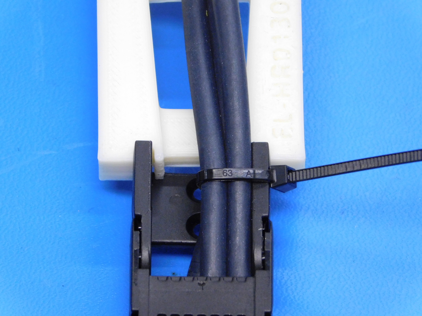
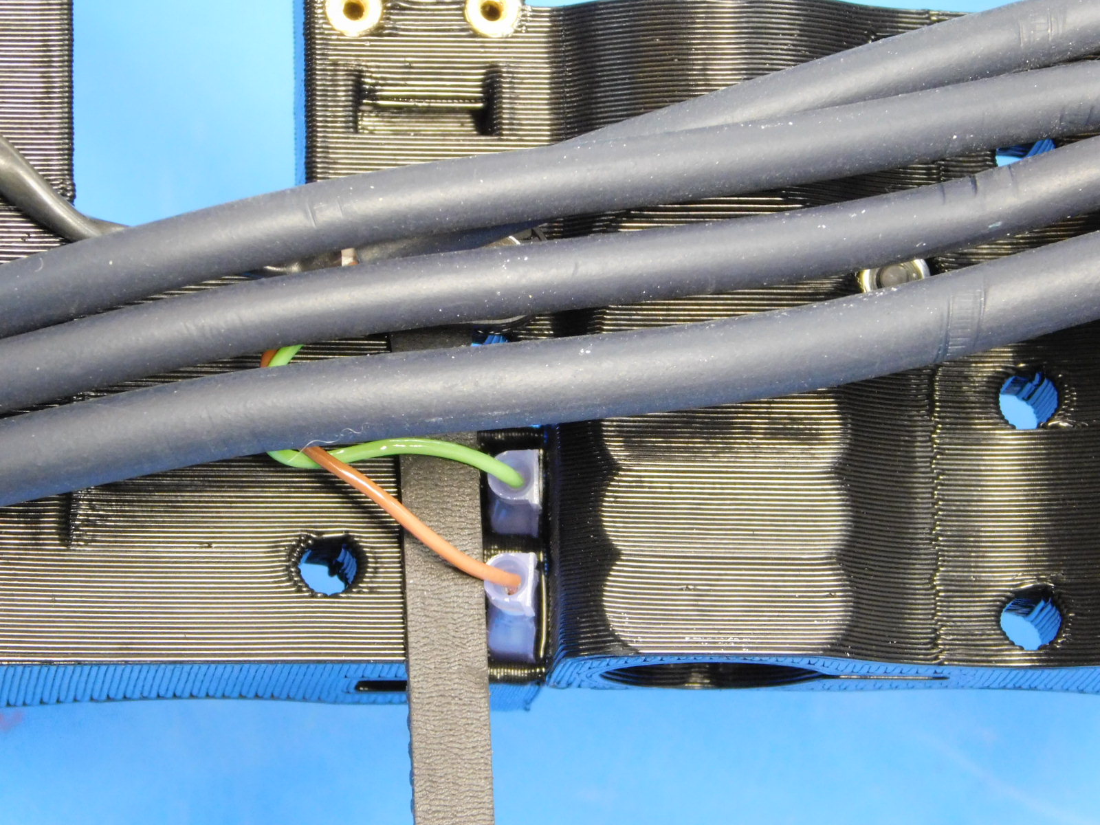
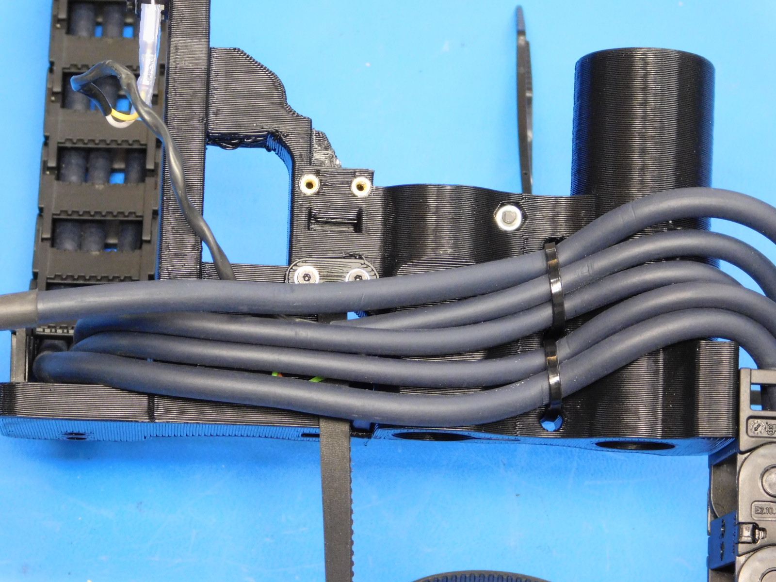
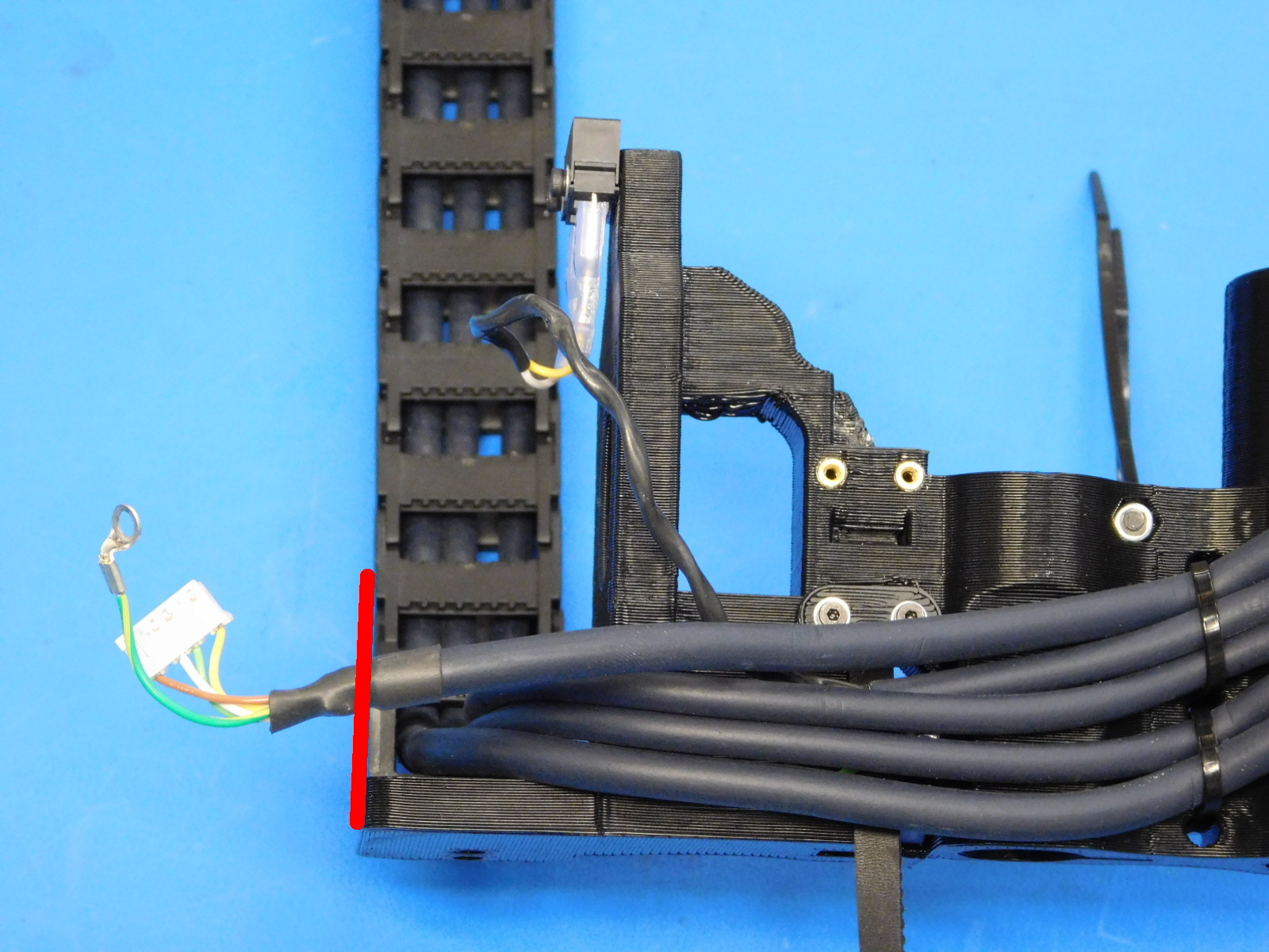
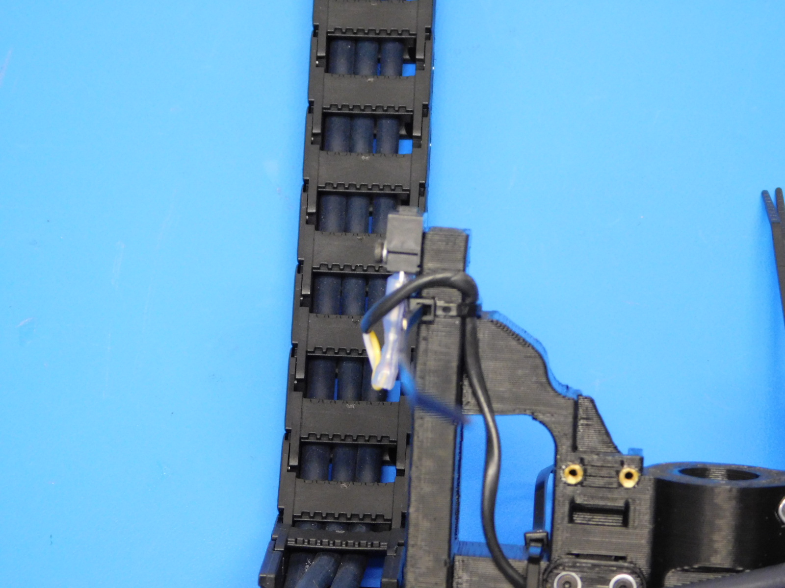
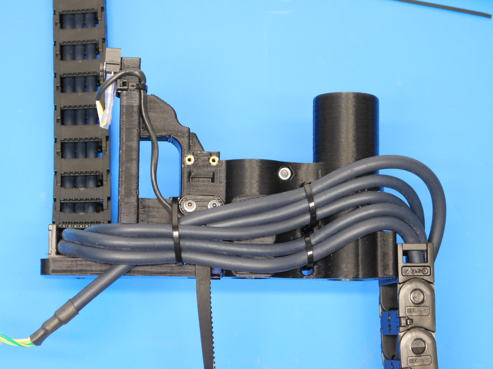
Starting from the opposite side of the X-End Motor part than the wires, with a cable tie [HD-MS0058], secure the two lower wires to the lower cable mount area of the X-End Motor. The cable tie latch must be on the opposite side of the X-End Motor part than the wires. See attached picture [reference#4]
Same as above, beginning from the opposite side of the X-End Motor part than the wires, with a cable tie [HD-MS0058], secure the three upper wires to the upper cable mount area of the X-End Motor. The cable tie latch must be on the opposite side of the X-End Motor part than the wires. See attached picture [reference#5]
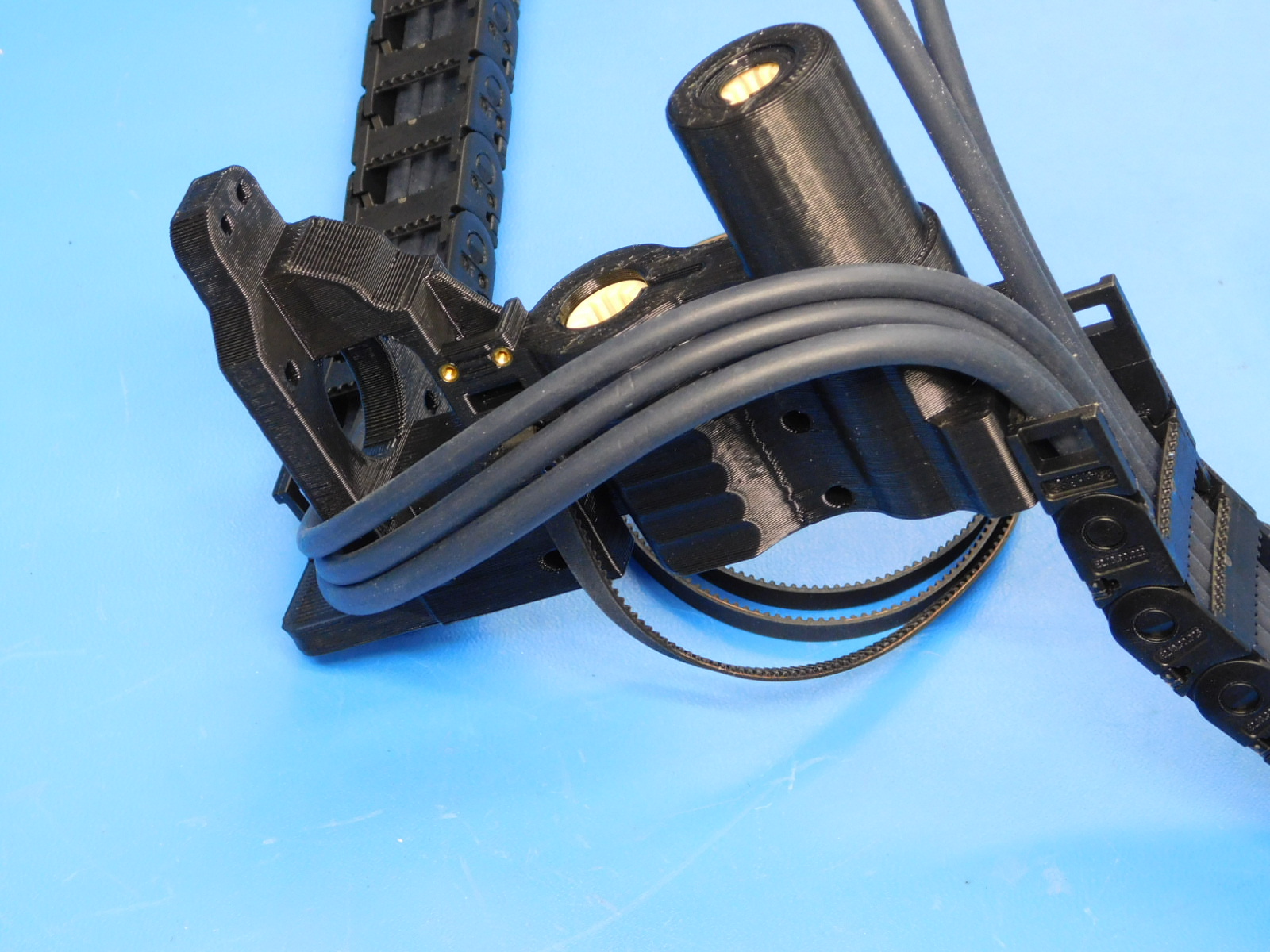
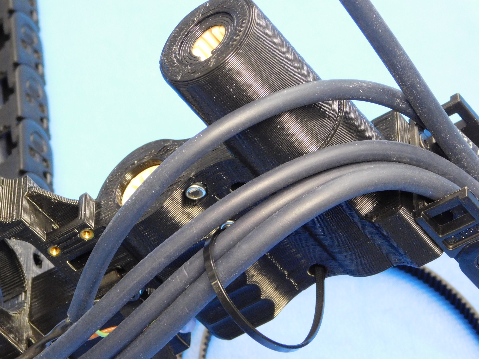
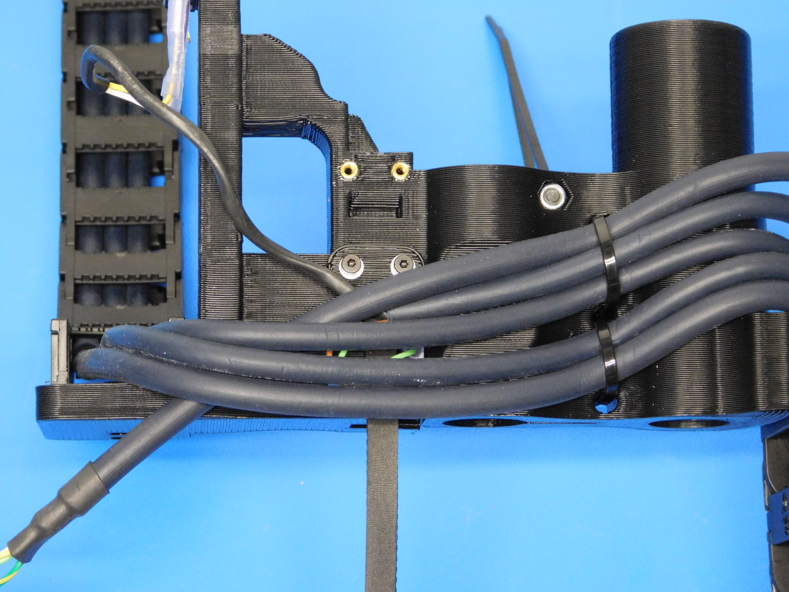
Pass the X-Motor Cable underneath the three extruder harness cables, as pictured.
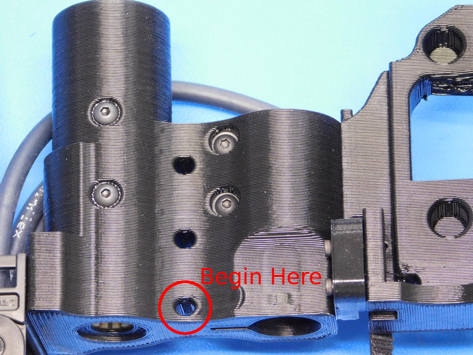
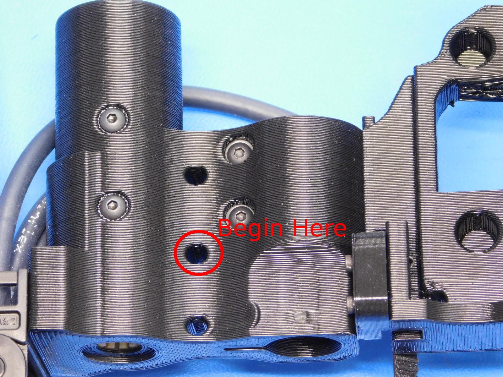
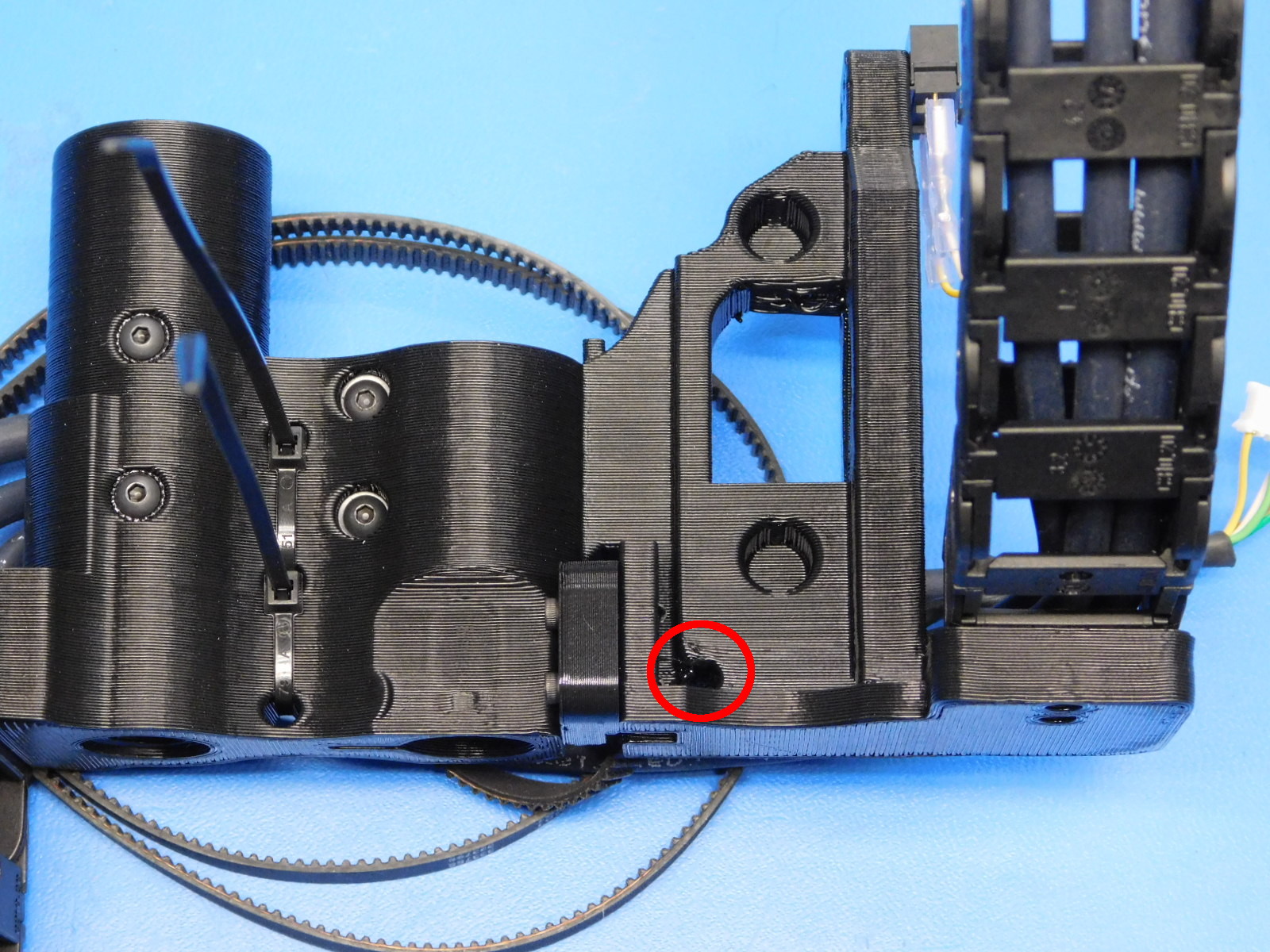
With a cable tie [HD-MS0058], begin through the highlighted hole in [reference#6], secure the five wires to the cable mount area nearest the Motor mount of the X-End Motor part.
The cable tie latch must be on the opposite side of the X-End Motor part than the wires. See attached picture [reference#7]
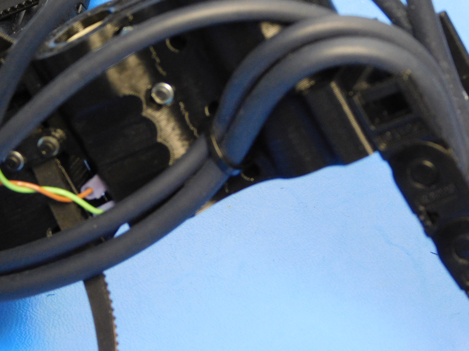
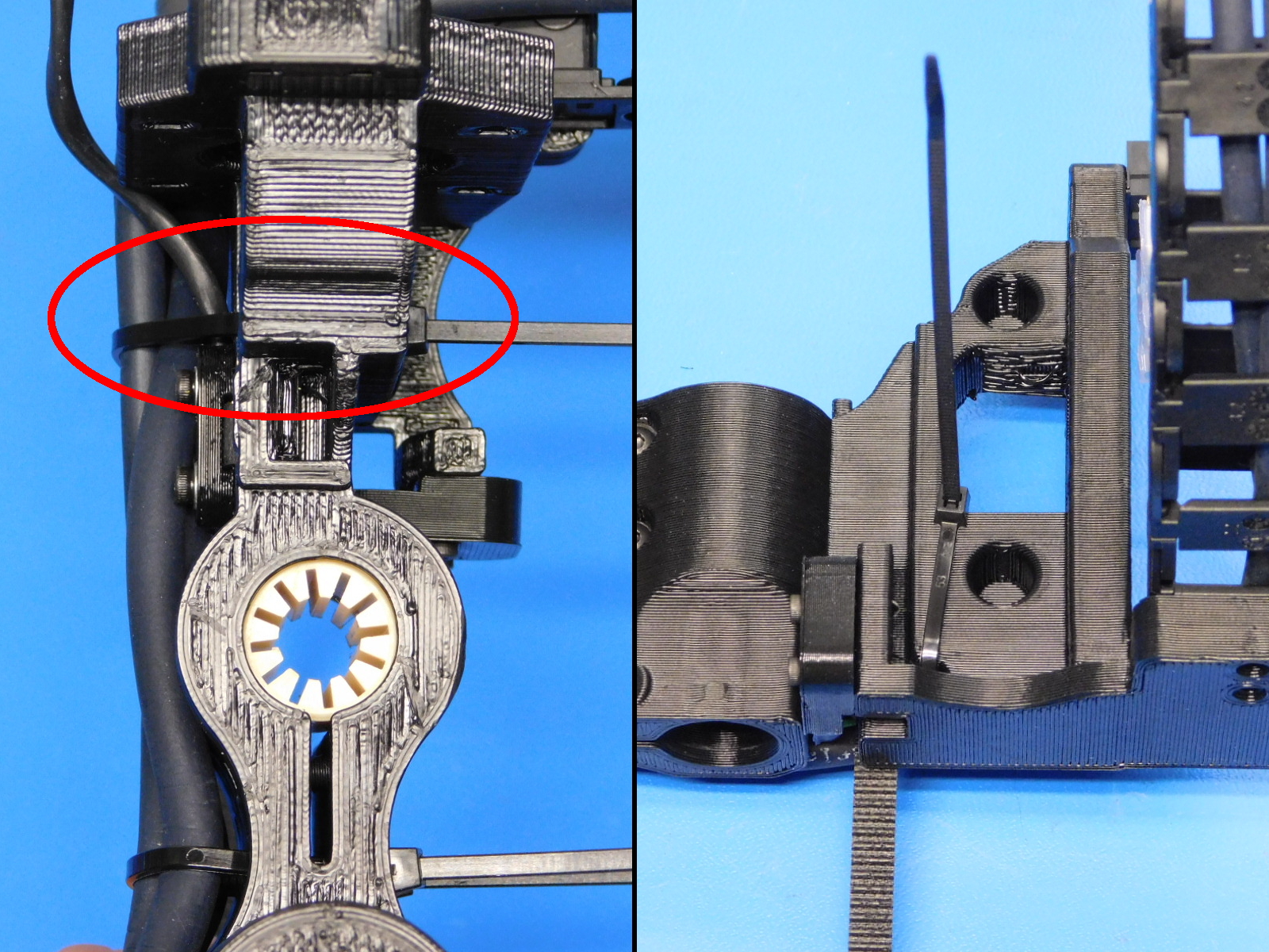
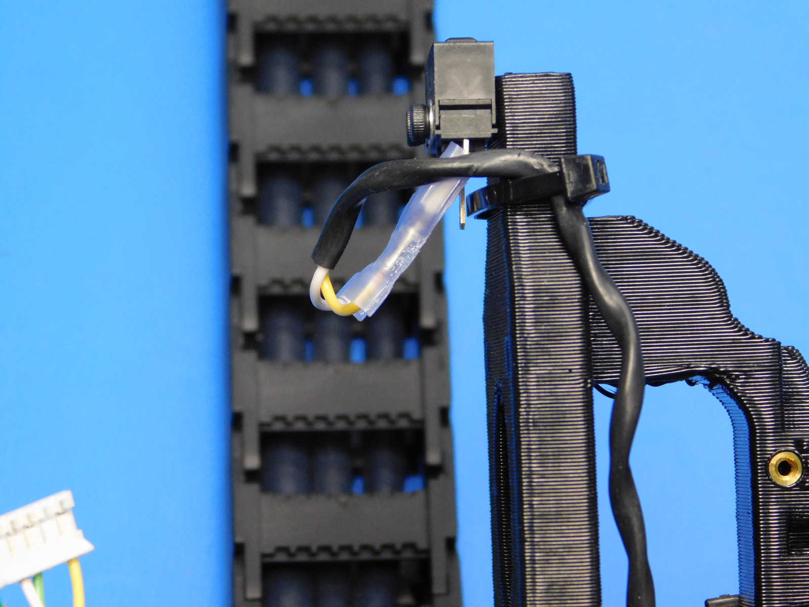
With a cable tie [HD-MS0058] secure the Z-Max Endstop wires along the edge of the x end motor as pictured. [reference#8]
Be sure the zip tie is under the quick connect terminals on the endstop side and the wire is on the *FRONT of the printed part.
Cut all zip-ties flush, assembly should look exactly as pictured.
Note: The X motor cable's heatshrink should be aligned with the back of the X-End Motor part as pictured.
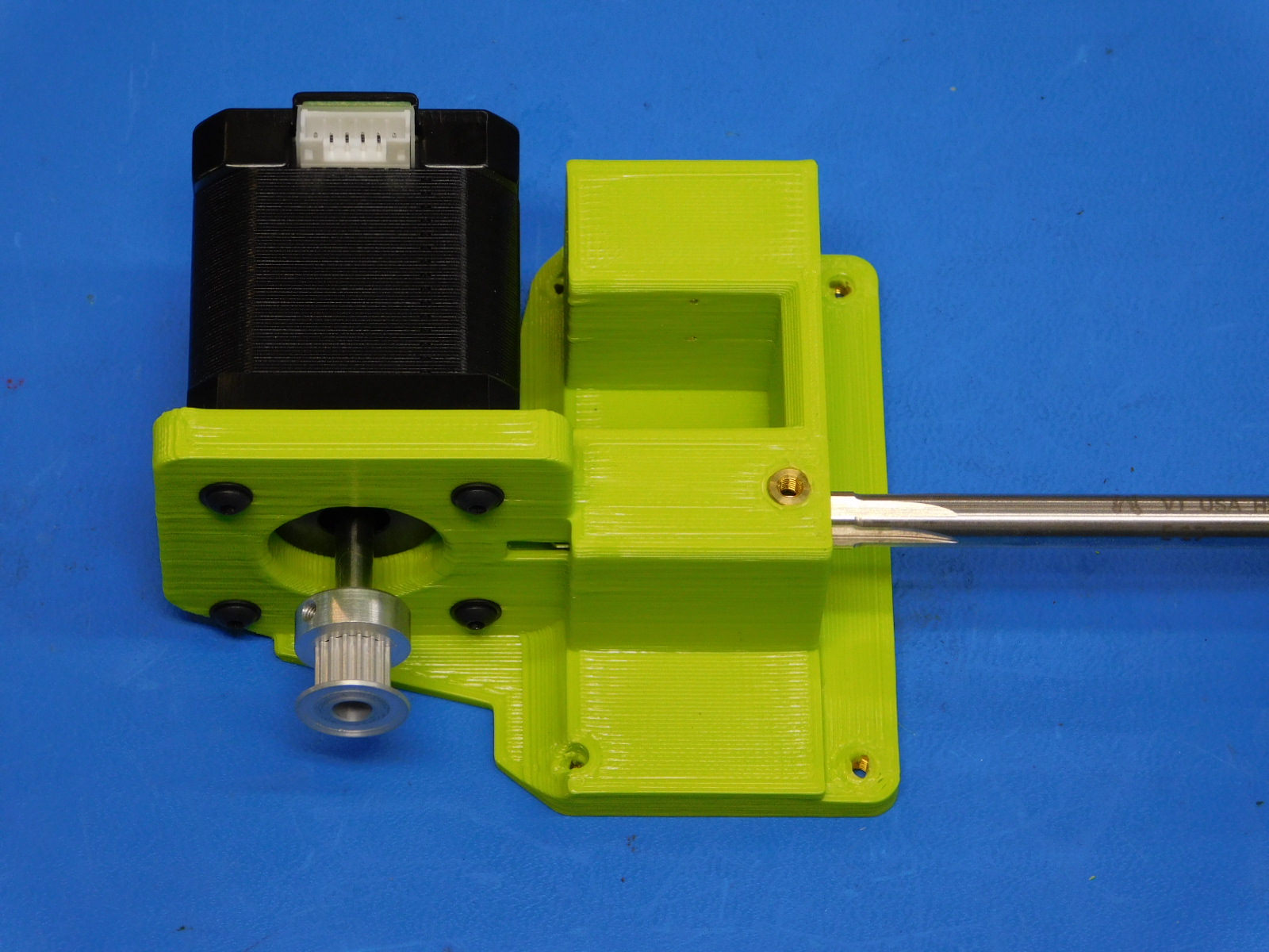
Attach a pulley [HD-MS0033] to a motor [EL-MT0029] , offset the pulley 6mm from the face of the motor, ensure one of the pulley set screws is aligned with the flat segment of the motor shaft, secure pulley in place with two set screws already installed in the pulley, tighten screws securely.
Bend the terminals of the Z-Max Endstop Switch outward to make space for the X-Motor, as pictured.
Attach the motor (with the connector oriented down toward the bottom of the X-End Motor assembly) to the X-End Motor assembly with 4x- M3x12 SHCS [HD-BT0039] with M3 washers [HD-WA0038], tighten screws in 8 in*lbs.
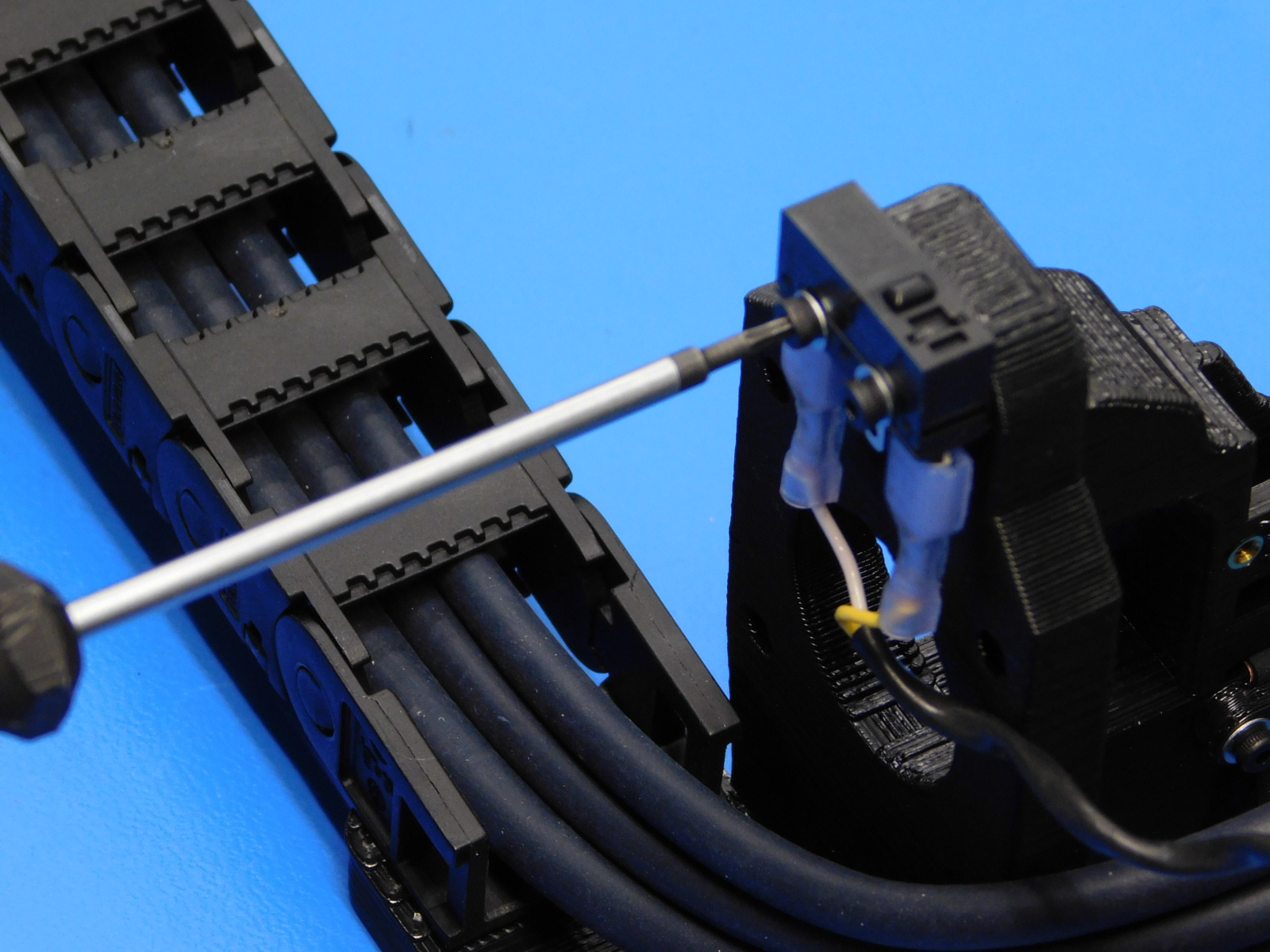
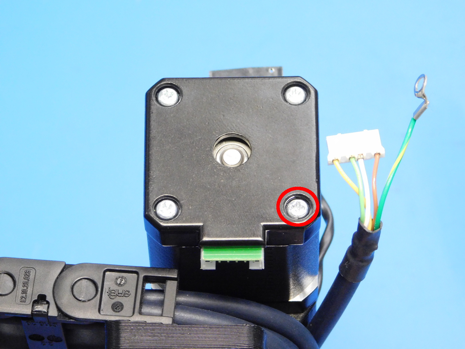
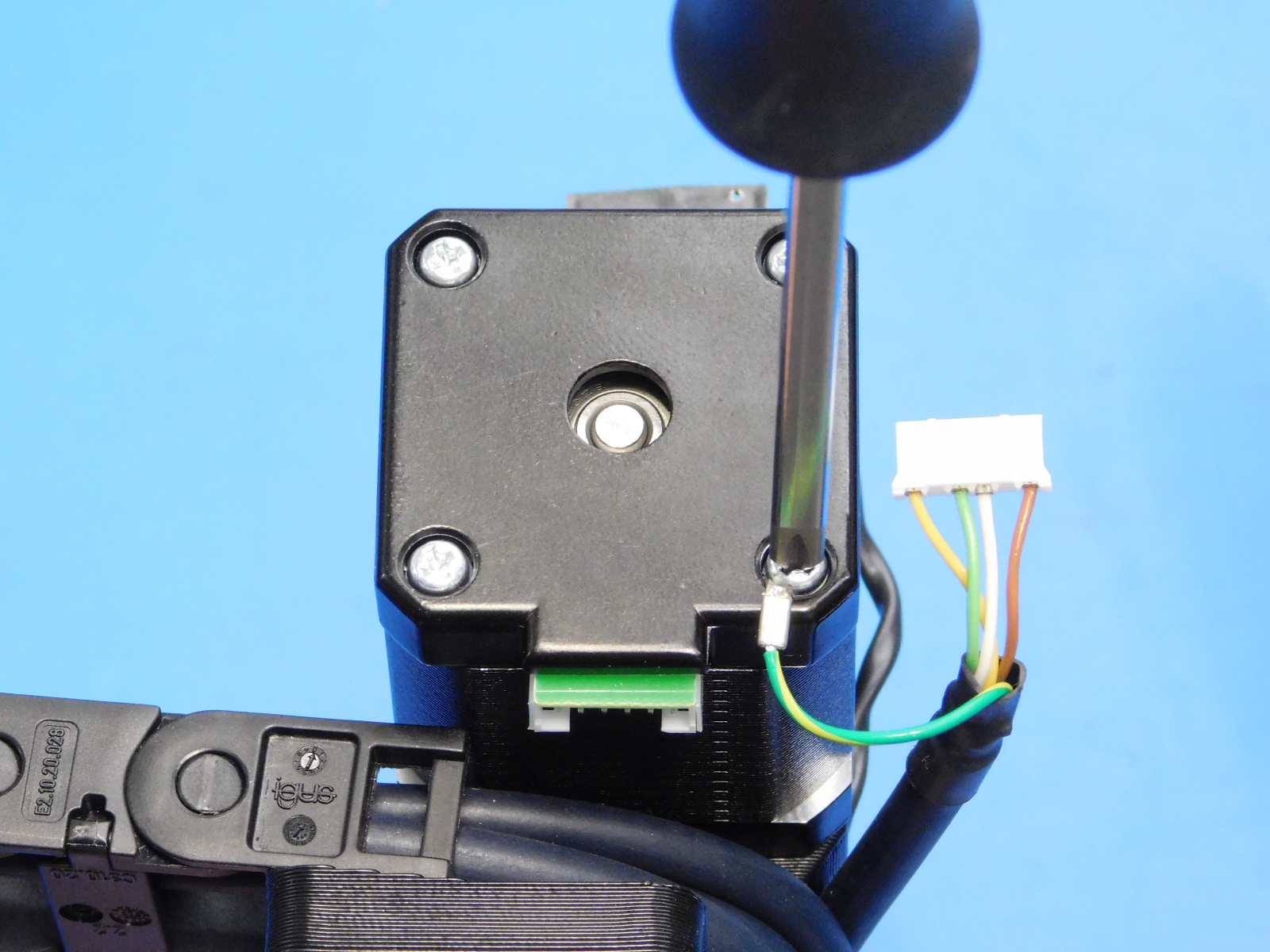
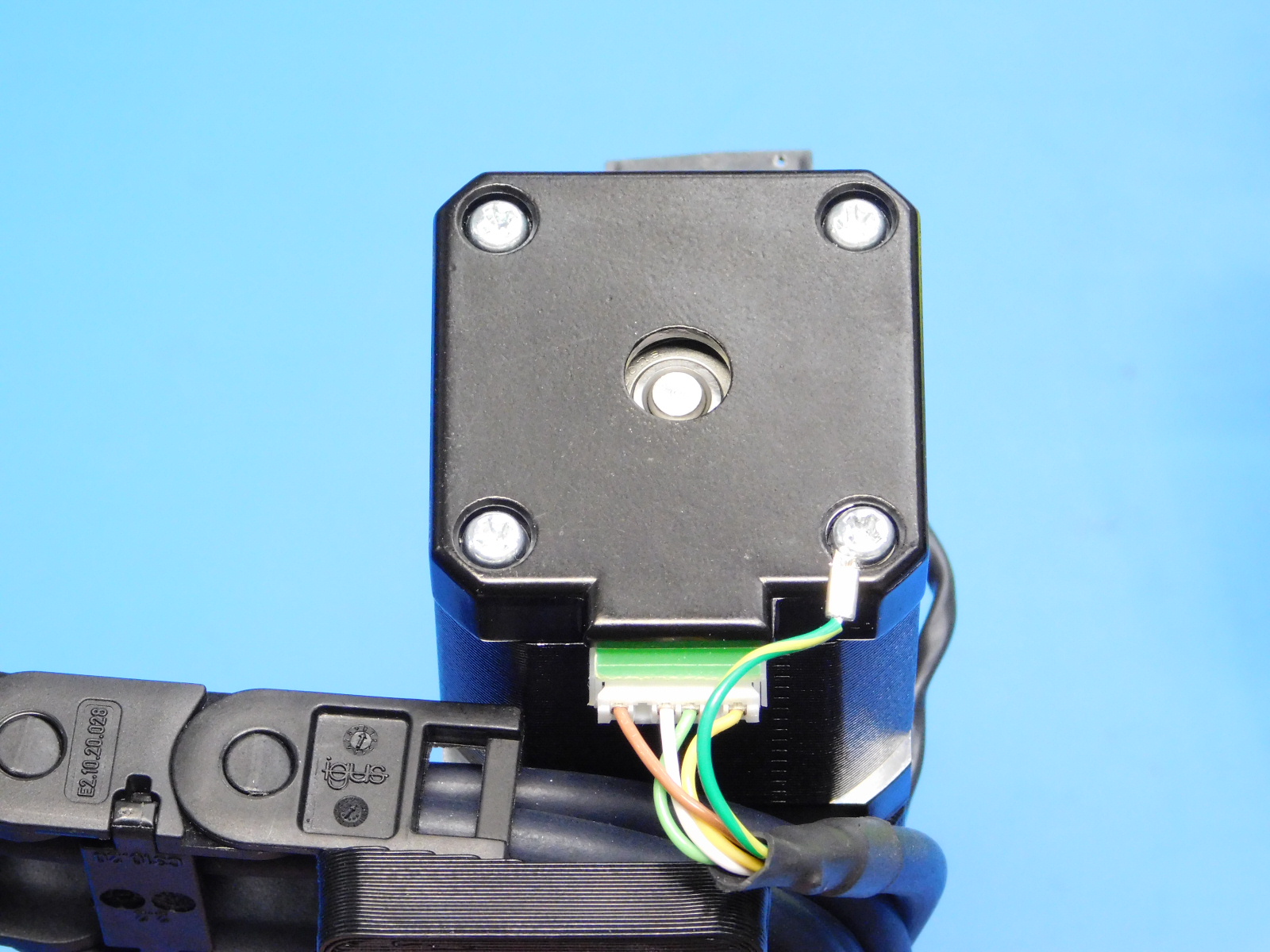
Remove the lower right phillips head screw from the back of the motor just installed [reference#9], install the screw into the ring terminal from the X Motor cable, re-install the screw until the head is again recessed and tight.
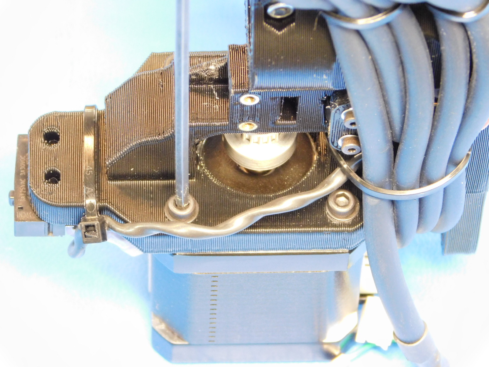
Connect the JST connector to the motor as pictured.
Using an 8mm part reaming tool, ream the 8mm smooth rod hole on the Z-Lower printed part [PP-IS0049] that has the M3 insert. Do NOT ream the slot; this can damage the dowels and the reaming tool Take care to keep the tool straight and to not remove too much material which would result in a loose fitting rod. Do Not touch the reaming tool to the motor
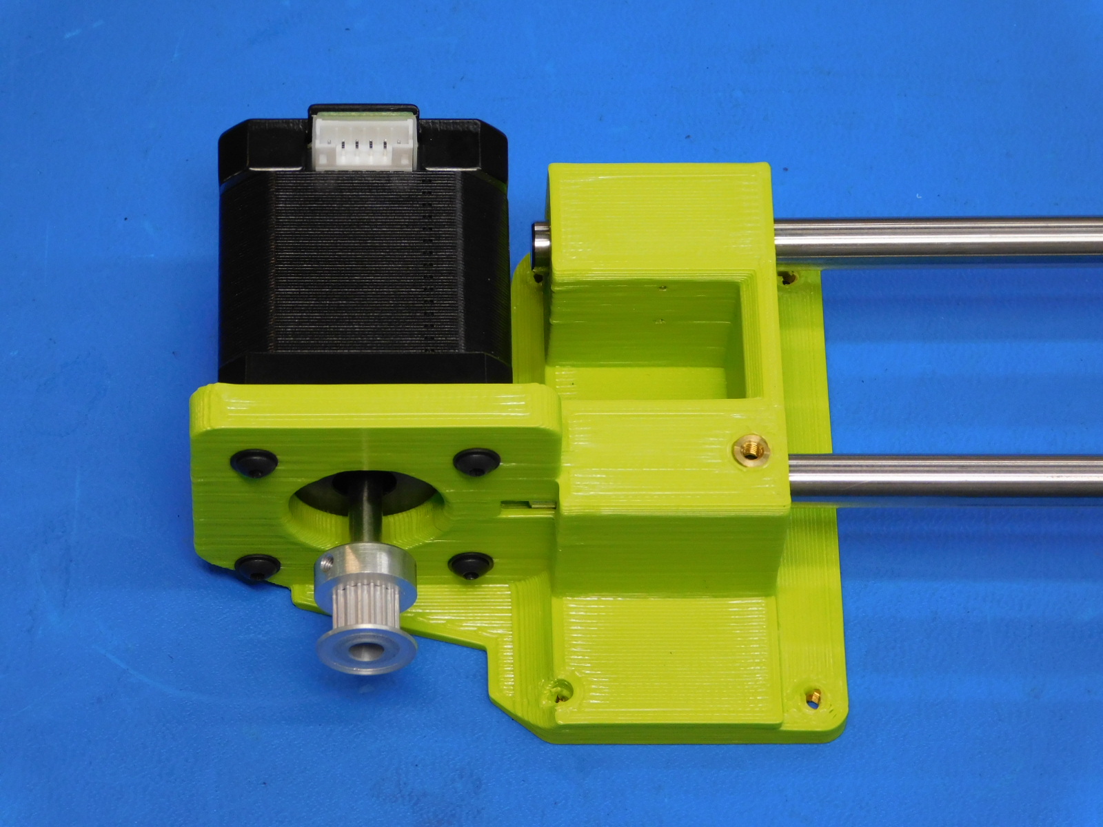
Install two Smooth Rods [HD-RD0035] into the Z-Lower [PP-IS0049]
Install the X-End Motor assembly (with cables, switches, and motor attached) onto the Z Lower Left and Smooth Rods assembly as pictured.
Using an 8mm part reaming tool, ream the two 8mm smooth rod holes on the Z-Upper Left printed part [PP-IS0050].
Take care to keep the tool straight and to not remove too much material which would result in a loose fitting rod.
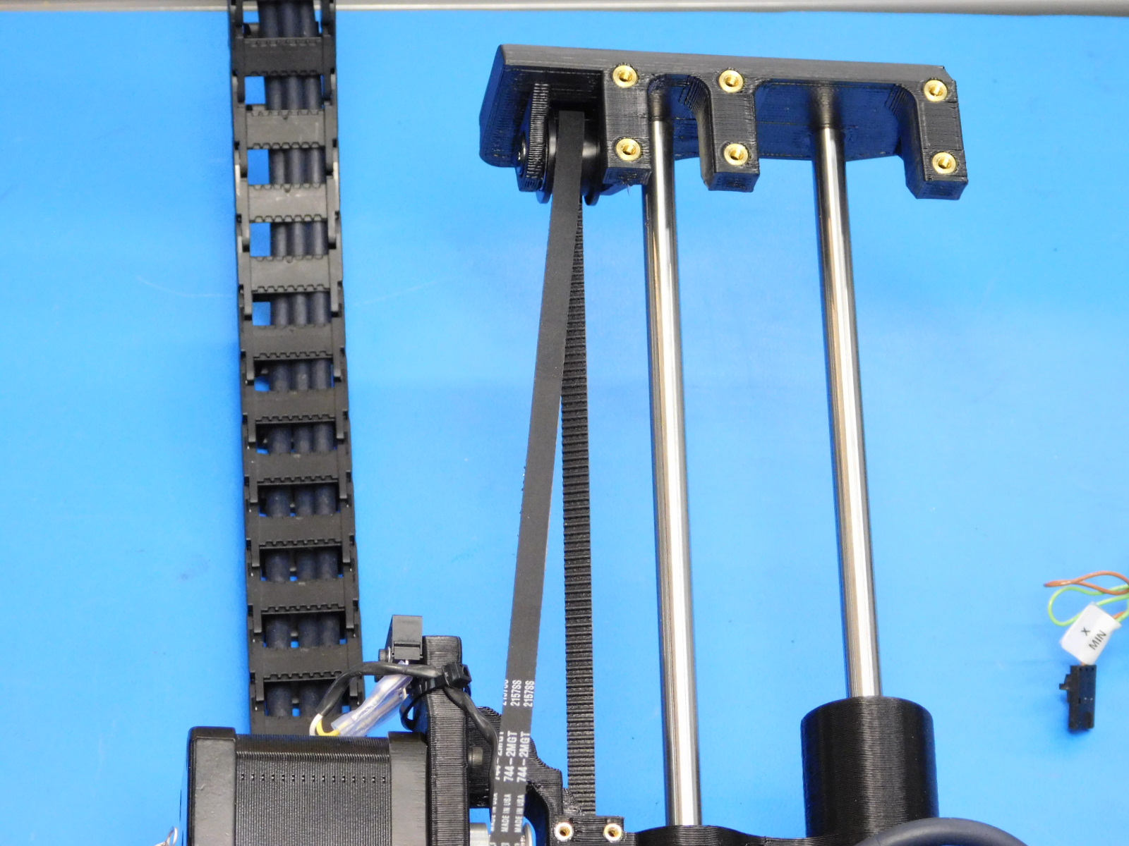
Install the Z-Upper Left [PP-IS0050] to the end of the smooth rods opposite the Z-Lower Left assembly as pictured.
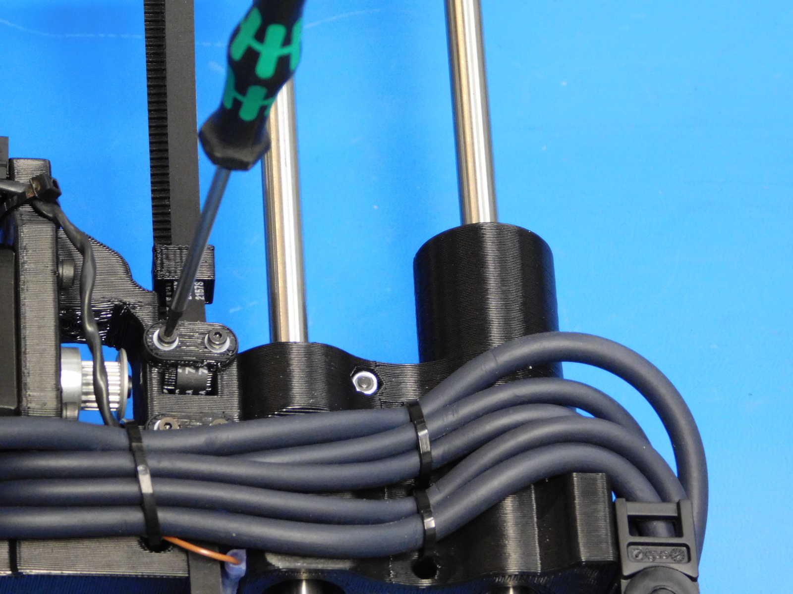
Install two M3x6 Set Screws [HD-BT0012] to the Z-Lower Right near the smooth rods, do not tighten.
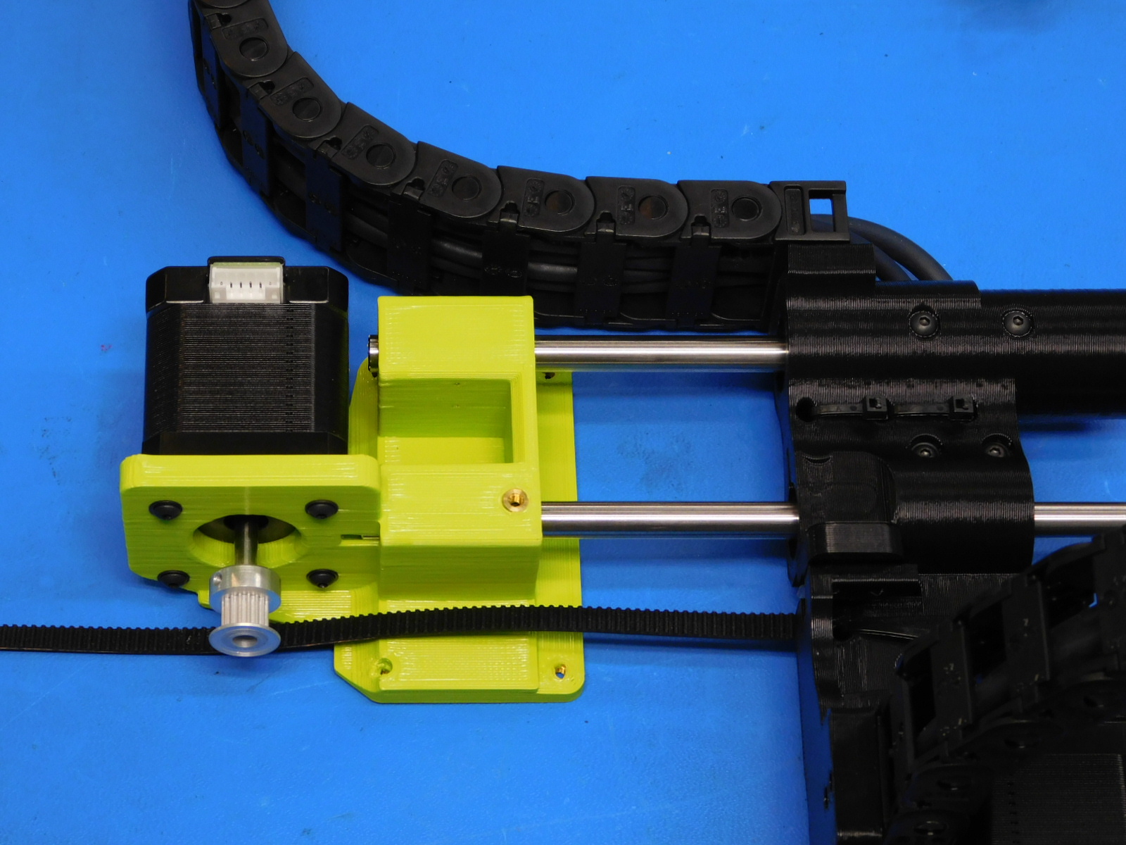

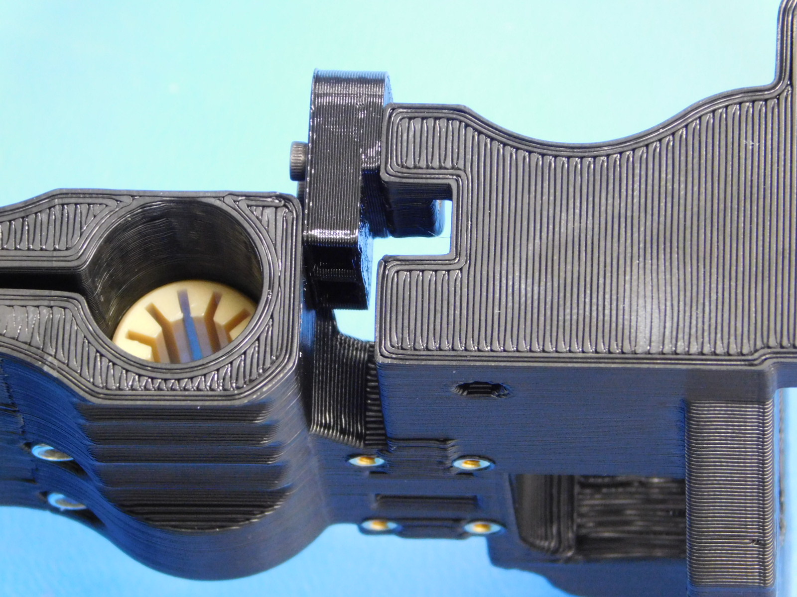
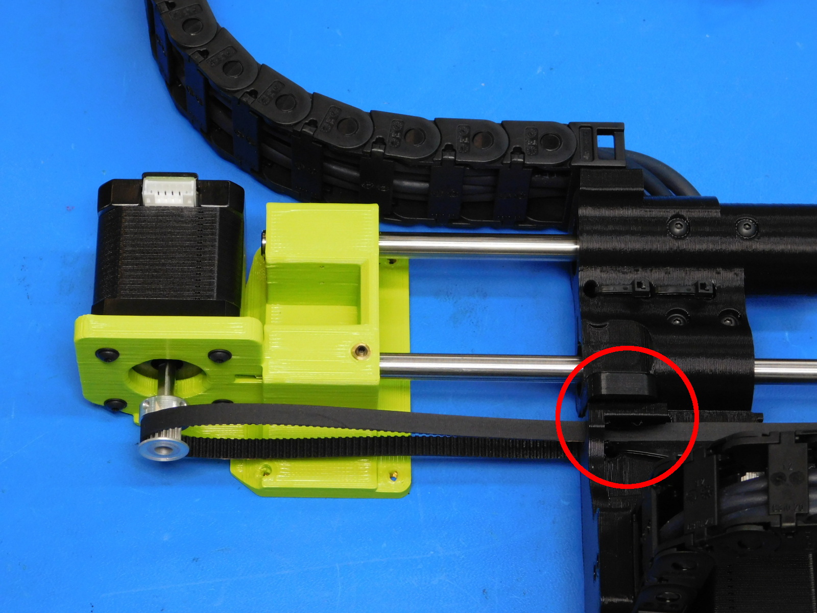
Route the belt (attached to the X-End Motor assembly during step 3) down around the Z-Left Motor and up through the hole in the X-End Motor printed part (behind the X-Min Bump Stop).
Continue through the bearing in the Z-Upper so that the belt makes a loop back to the X-End Motor printed part.
Ensure the belt has not been twisted during this process.
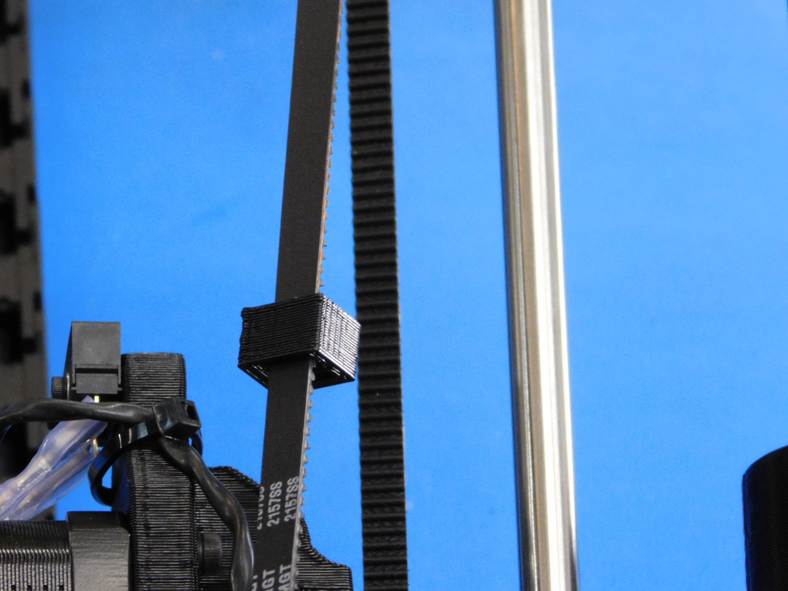
Slide one Belt Tensioning Collar [PP-GP0307] onto the belt with the narrow end of the collar facing the Z-Upper.
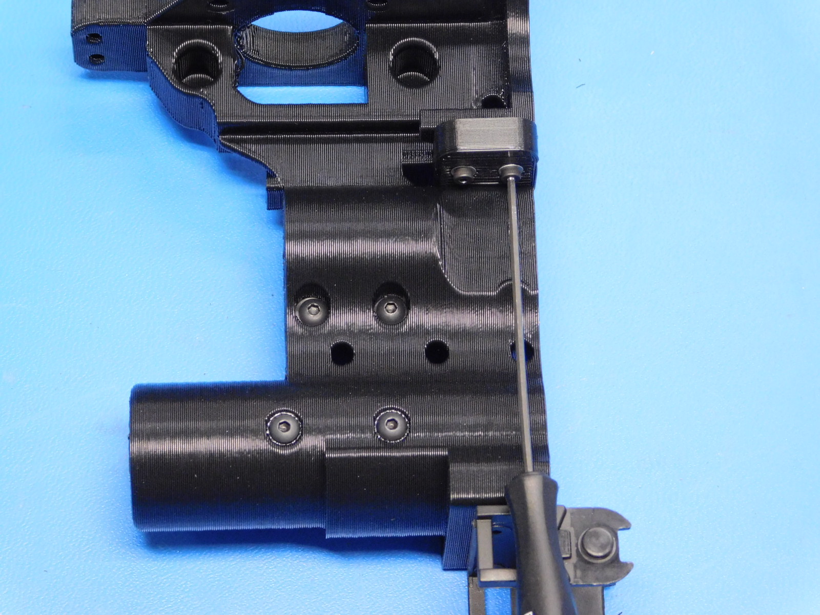
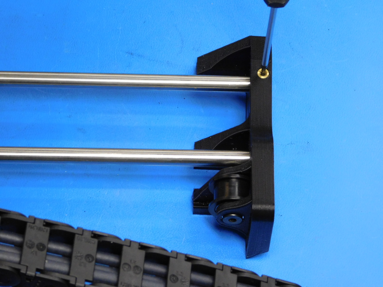
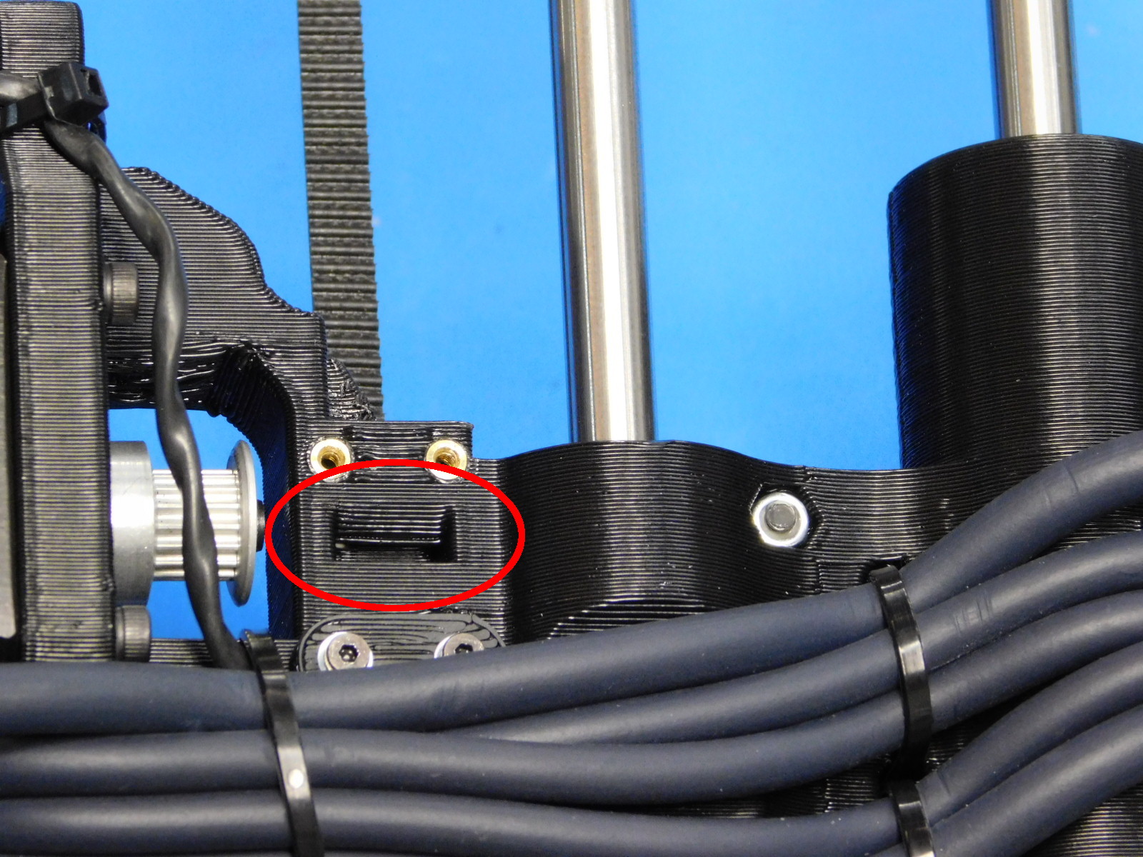
Slip the belt through the upper slot in the Z-Belt clamp feature, see [reference#10]
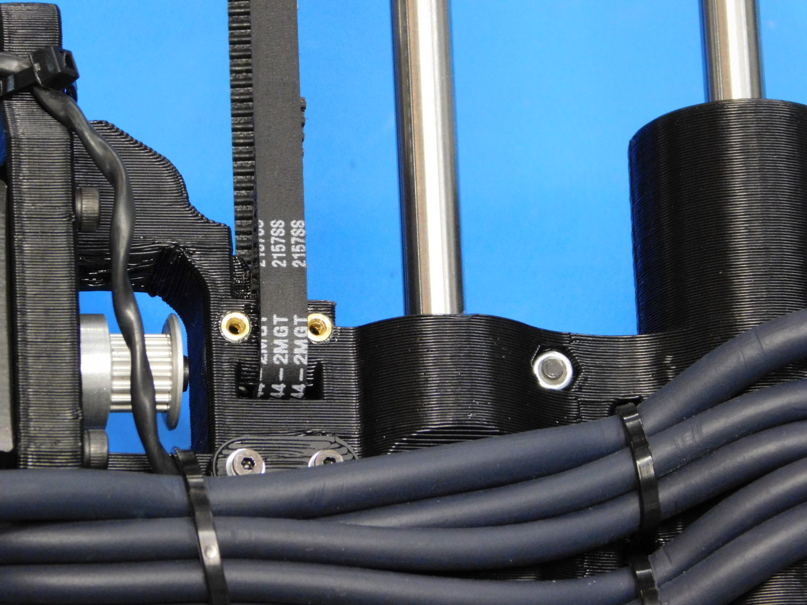
The belt should be left loose at this time, secure it in place with one Z-Belt Clamp [PP-GP0308] and two M2x6 SHCS [HD-MS230] with M2 washers [HD-WA0012]
See attached picture [reference#11]
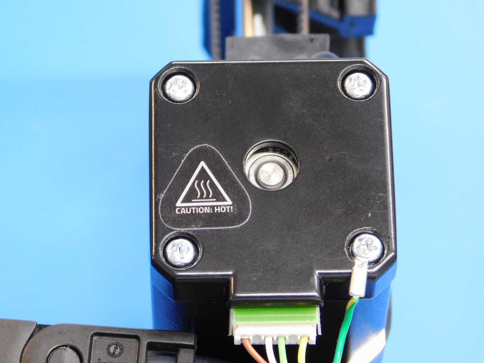
Apply 1x- [DC-LB0154] Caution Hot Sticker to the rear of the X-Motor as shown
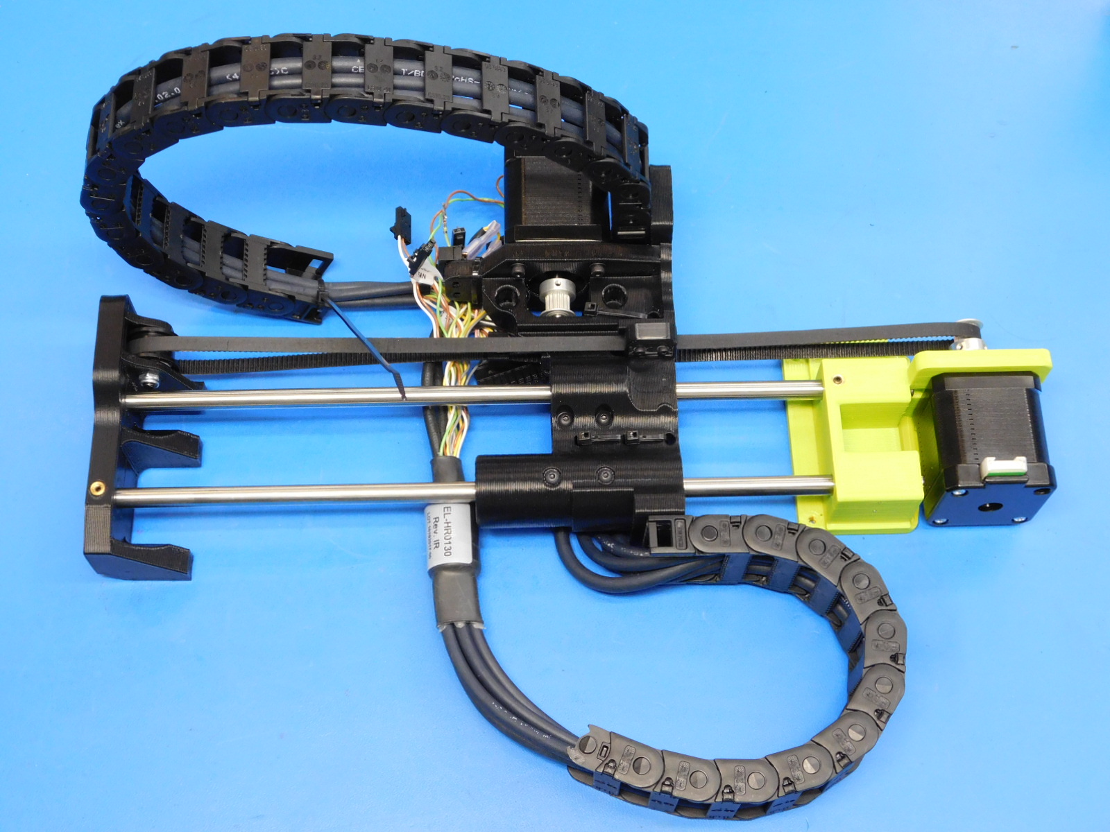
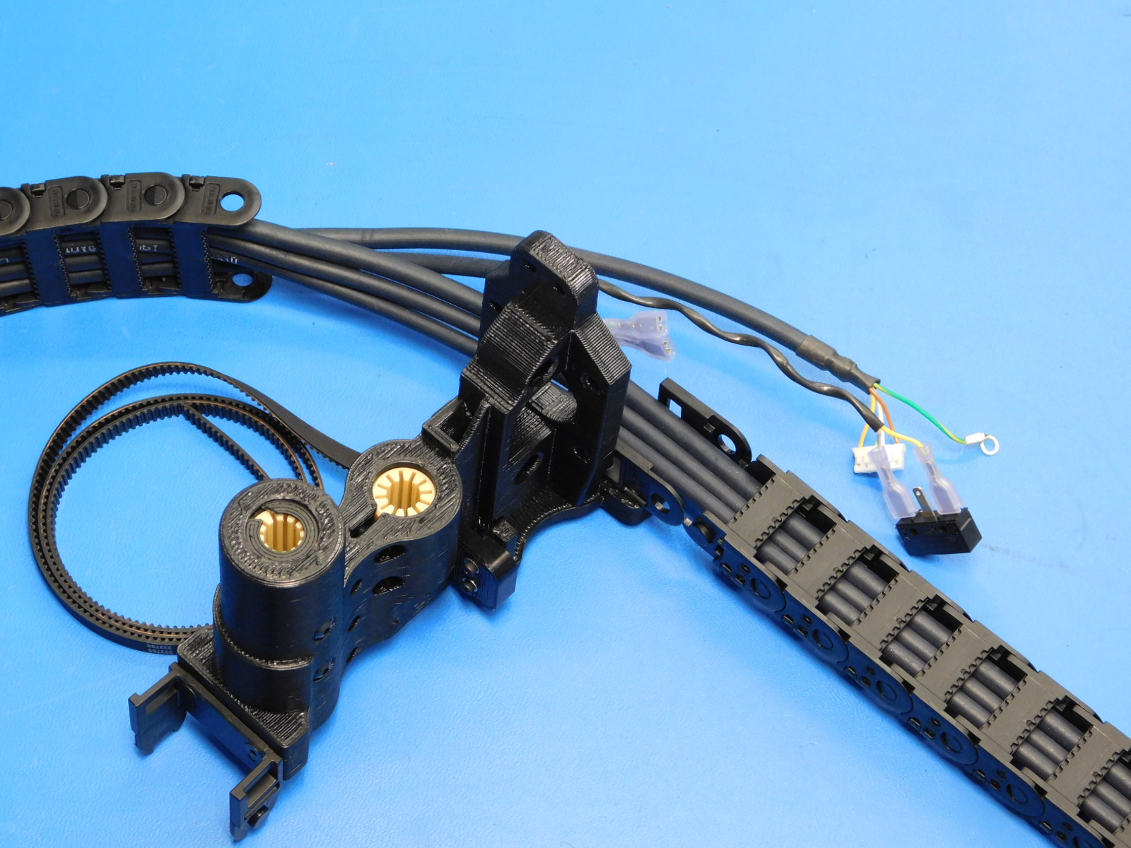
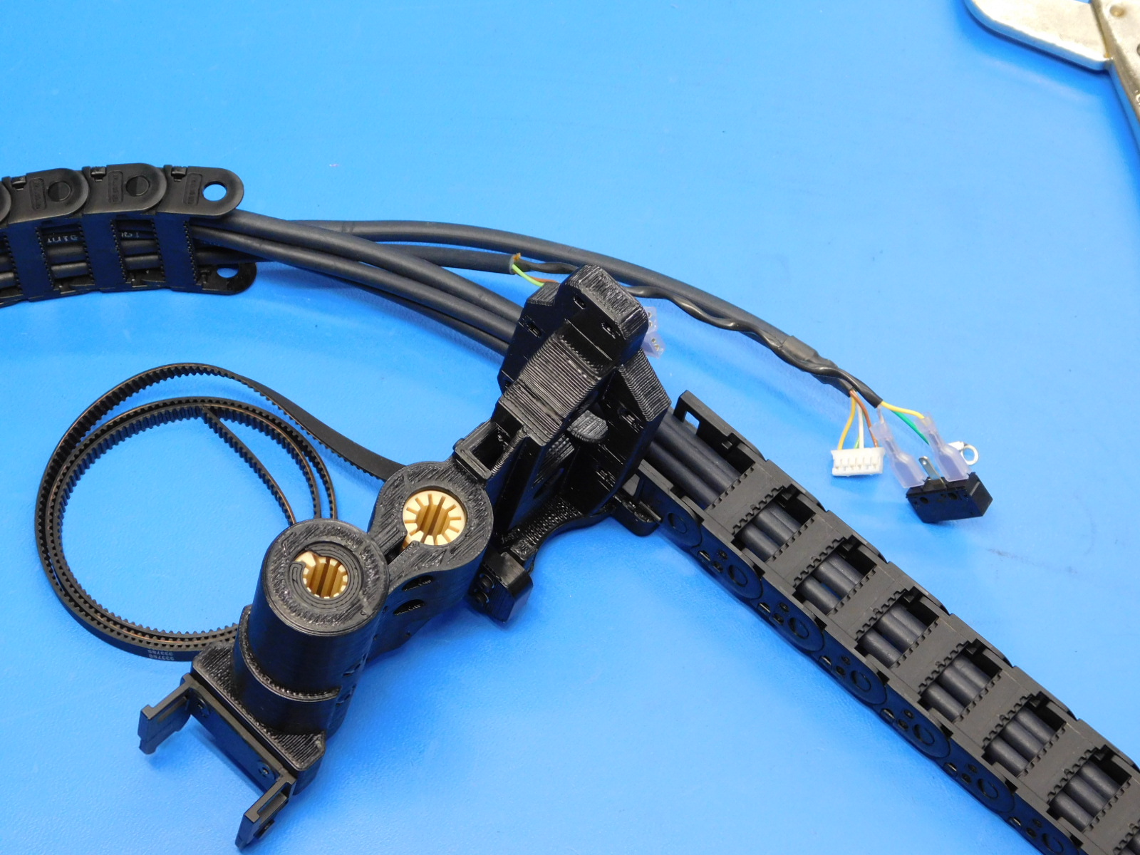
Make sure your completed work resembles the assembly shown at right
With the assembly laying on the workbench as shown, look between the table and the cables attached to the X-End Motor printed part; none of the cables should be touching the workbench. If contact occurs this indicates that the cables will likely rub the frame when this sub-assembly is installed to to the frame. In this case, refer to step 5 of this OHAI kit, making sure all instructions are followed.