Open HardwareAssembly Instructions
Guides for installation and assembly of the LulzBot line of products made by Aleph Objects, Inc.
Guides for installation and assembly of the LulzBot line of products made by Aleph Objects, Inc.
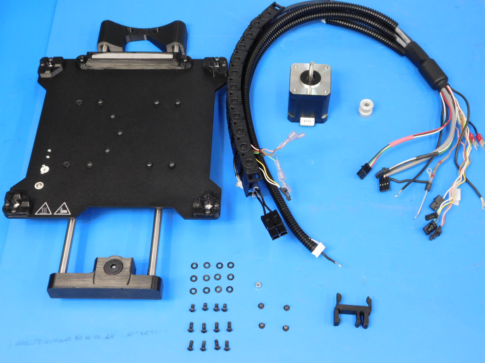
Gather parts:
1x- [AS-PR0102] Mini, Bed Plate Assembly
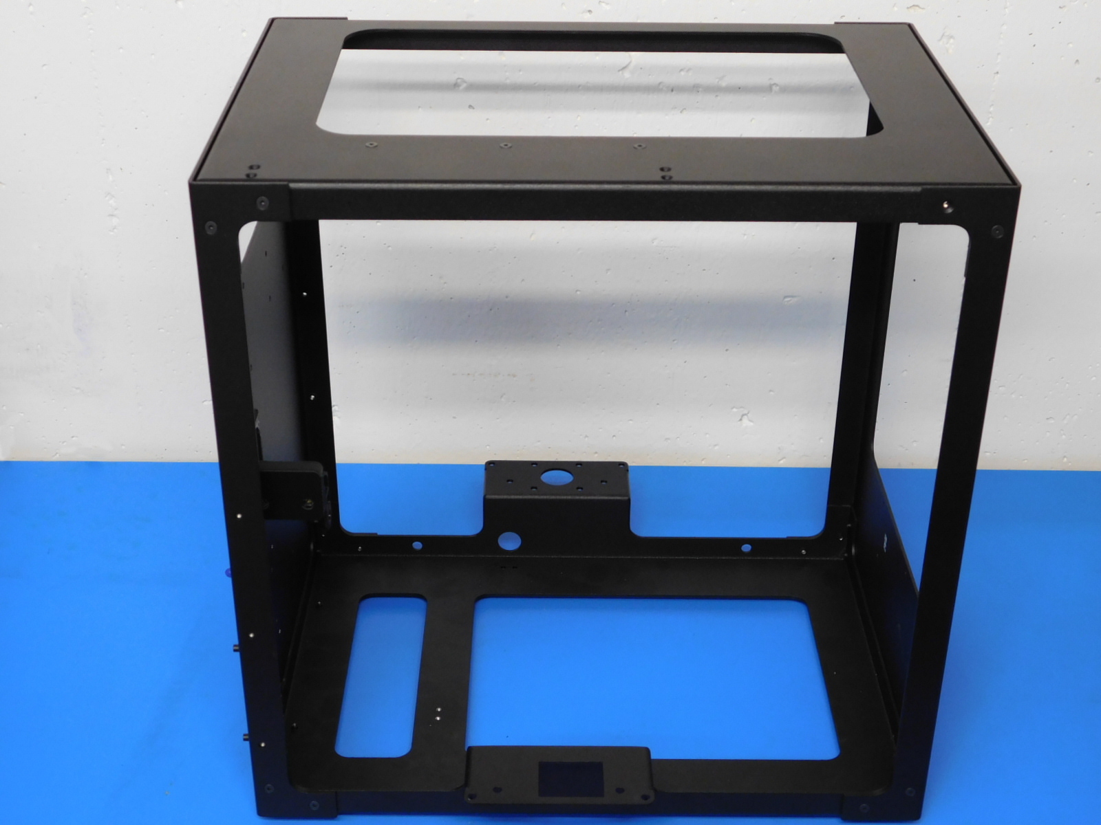
1x- Frame Assembly
1x- [AS-CB0071] Min2 Bed Harness
1x- [PP-GP0249] bed clip v3
1x- [AS-PR0089] Z Axis Right Assembly
1x- [AS-PR0099] Z Axis Left Assembly
24x- [HD-BT0128] M3 x 6 Bolt, FHCS Black-Oxide
8x- [HD-BT0137] M3 x 8 Bolt, BHCS, Black-Oxide
1x- [HD-NT0001] Metric Zinc-Plated Steel Nylon-Insert Locknut, M3 Screw size, .5MM pitch
12x- [HD-WA0038] Black-Oxide 18-8 Stainless Steel Flat Washer, M3 Screw Size, 3.2mm ID, 7.0mm OD
1x- [EL-MT0029] NEMA 17 Stepper Motor
4x- [HD-BT0140] M3 x 6 Bolt, BHCS Black-Oxide
1x- [HD-MS0033] GT2, 16 Teeth, timing pulley, AL
2x- [HD-MS0058] 8" cable tie
Tools needed:
2mm hex driver
5.5 Nut Driver
Flush Cutters
1.3mm Hex Driver
P2 Phillips screwdriver
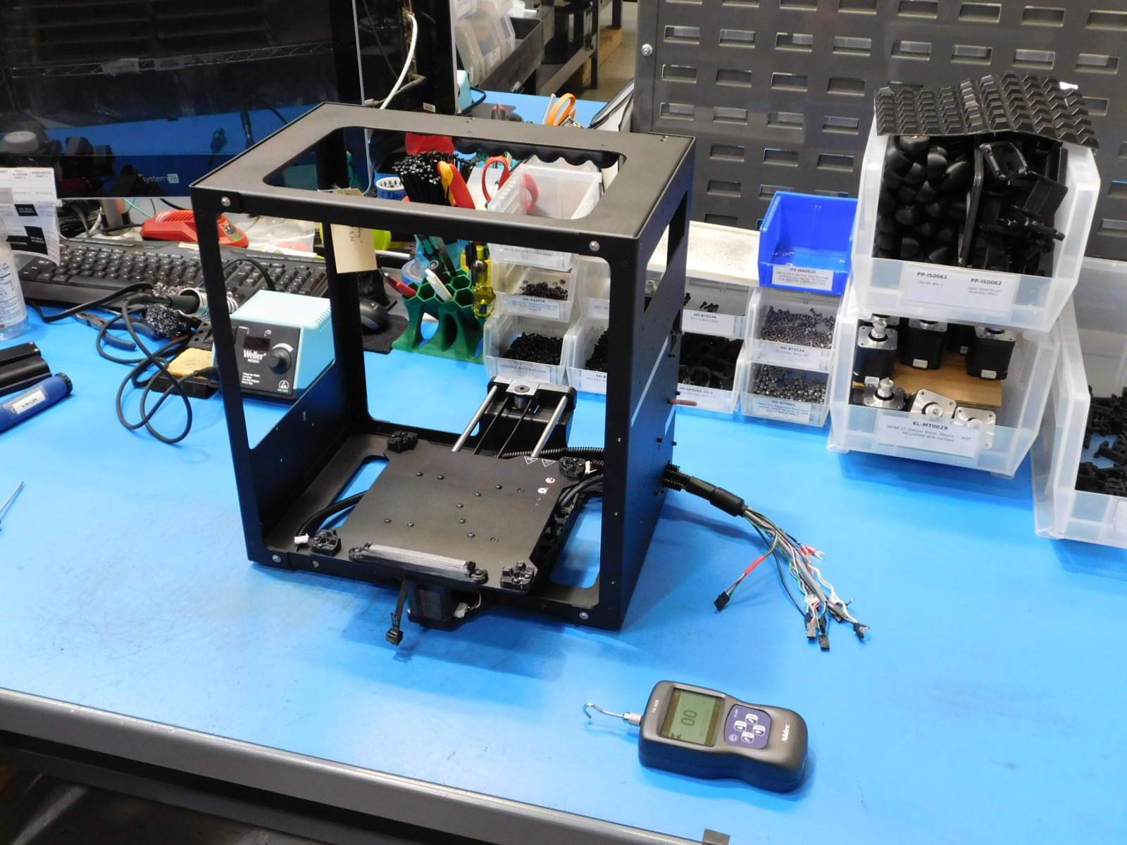
Place the Bed Plate Assembly plate side down onto the work station
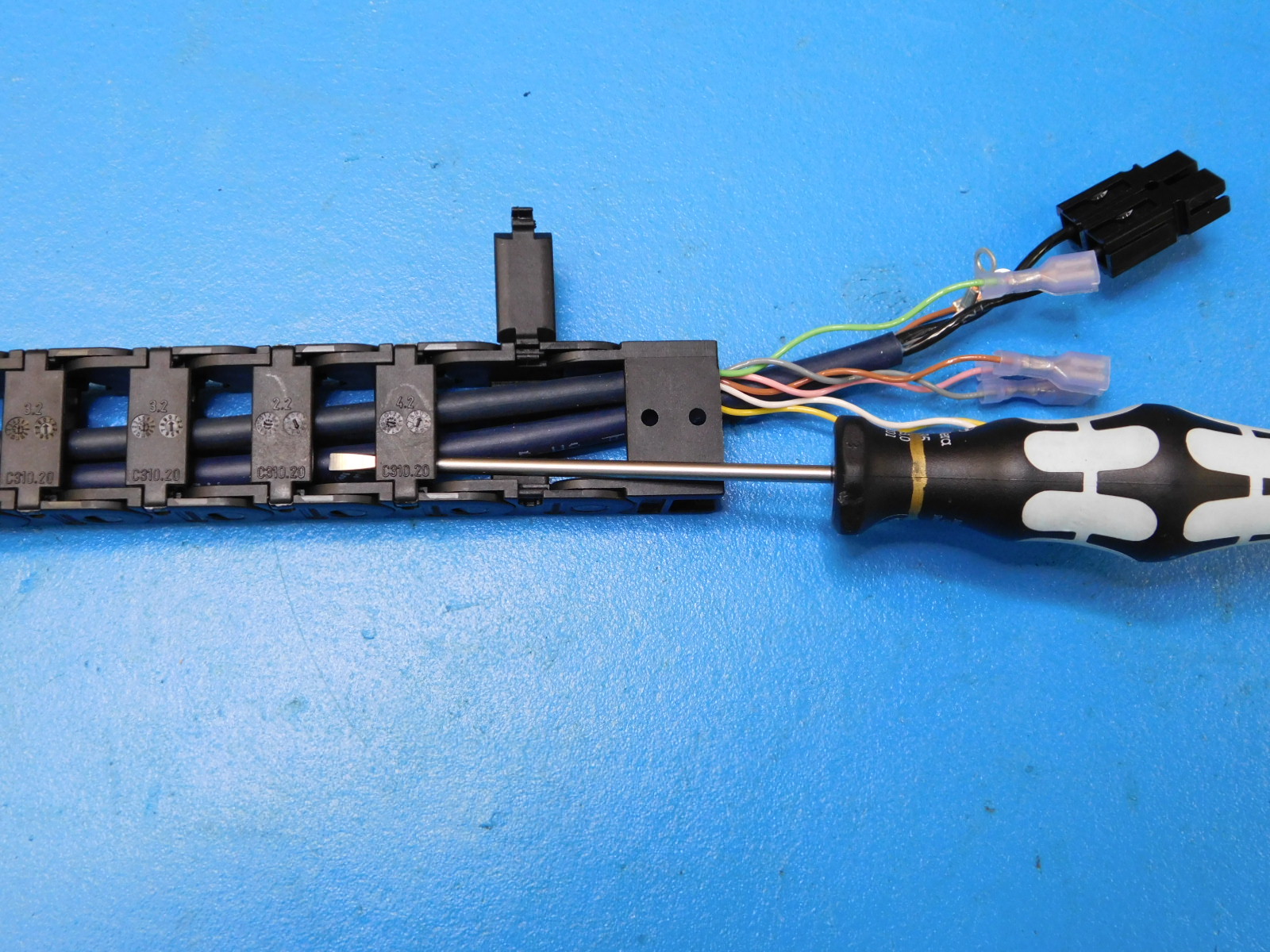
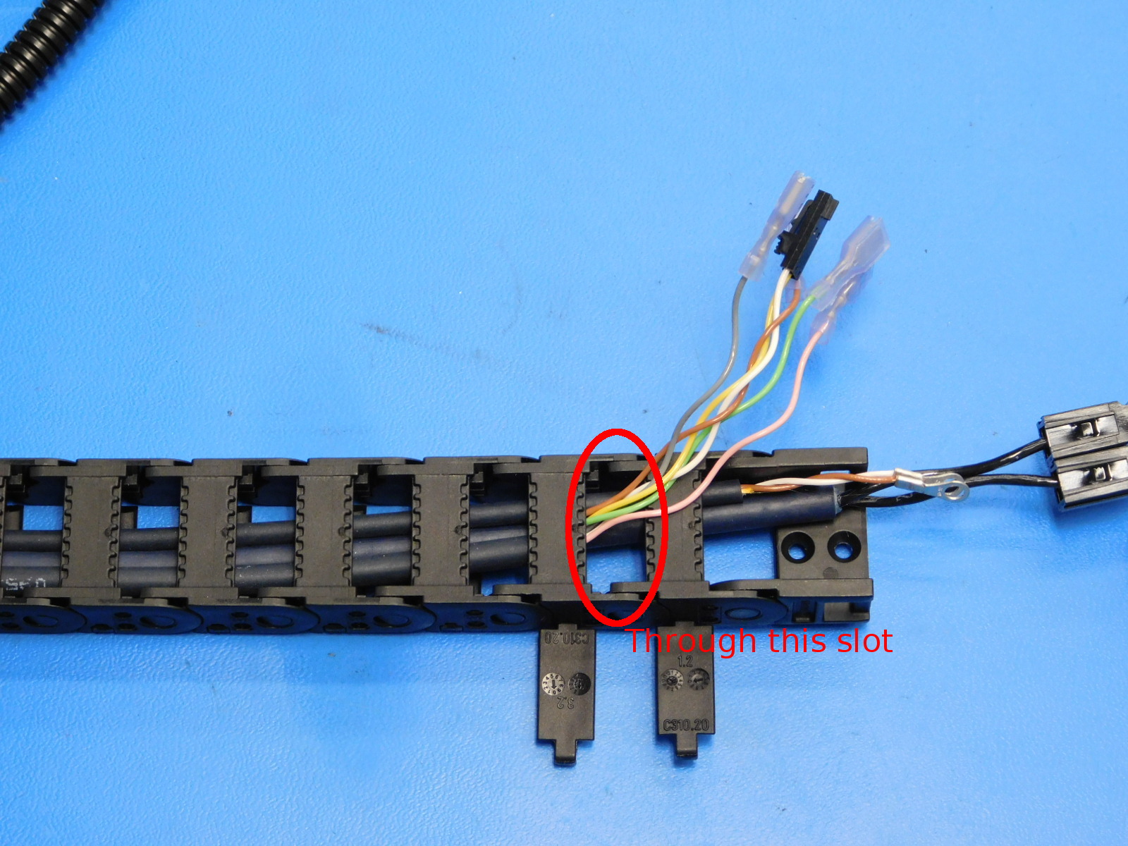
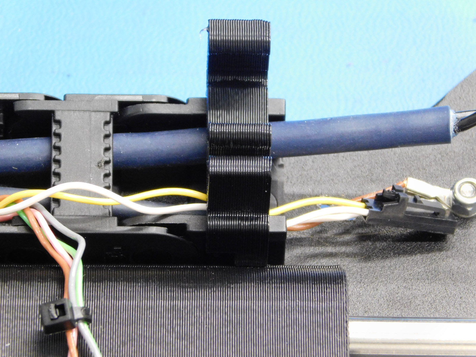
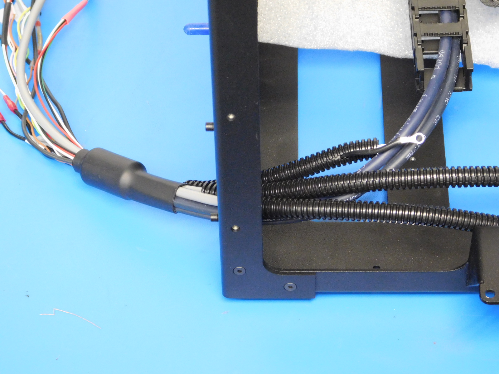
Route the Yellow/ White wire pair as well as the Green, Gray, Brown, and Pink wires through the last slot in the cable chain; using a standard screwdriver, open the last two backside access latches, send wires through the last slot in the top side of the chain, see [reference#1] , close the latches
Attach AS-CB0071 (Bed Harness) to the Bed Plate Assembly with two M3x 6 FHCS [HD-BT0128], tightened to 5in*lbs
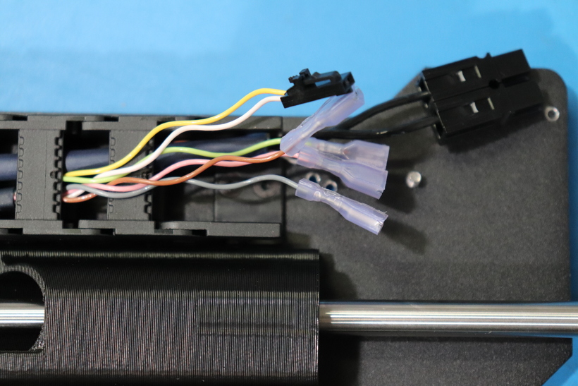
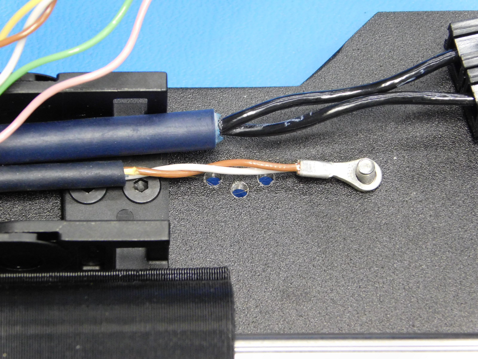
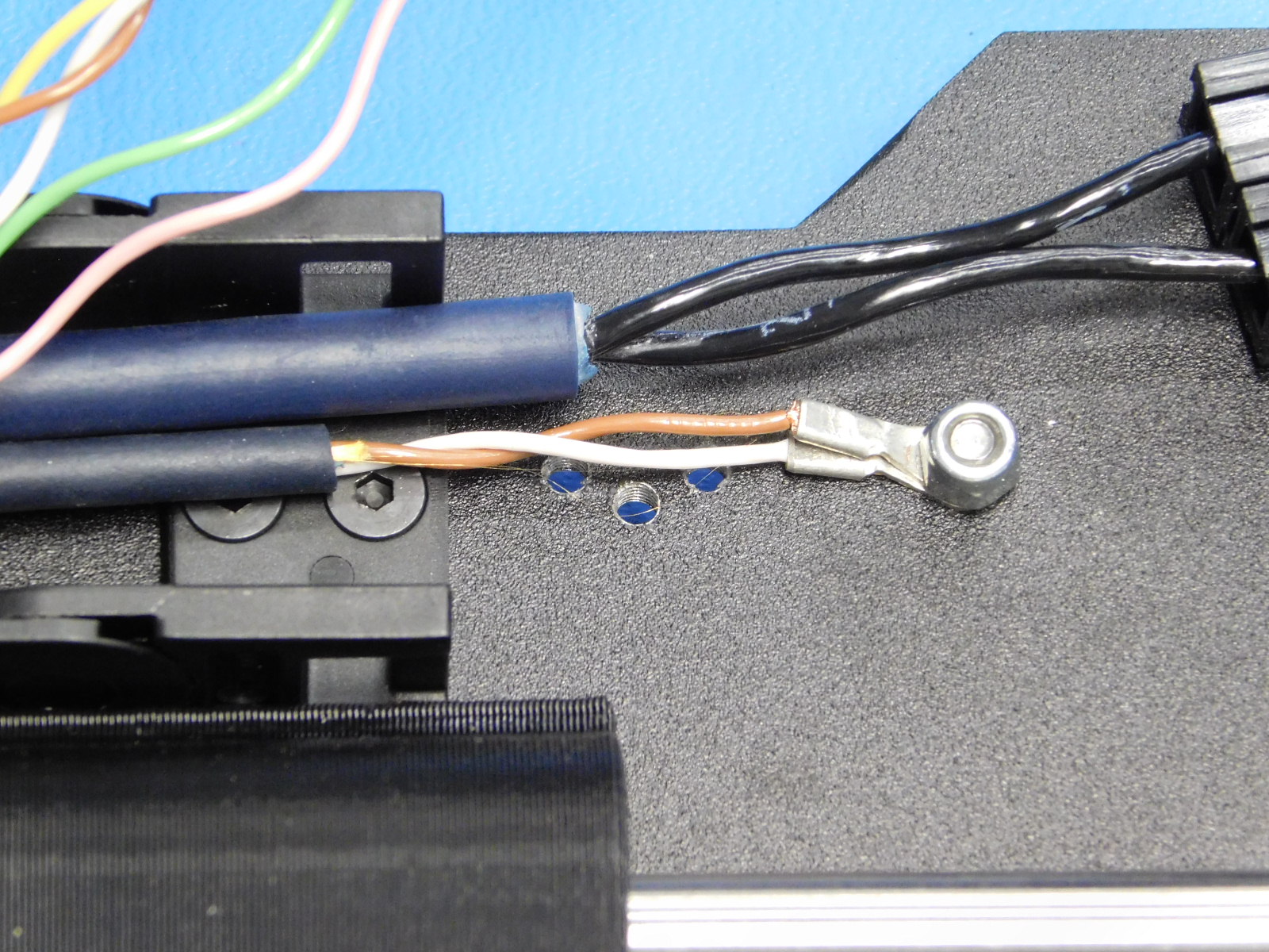
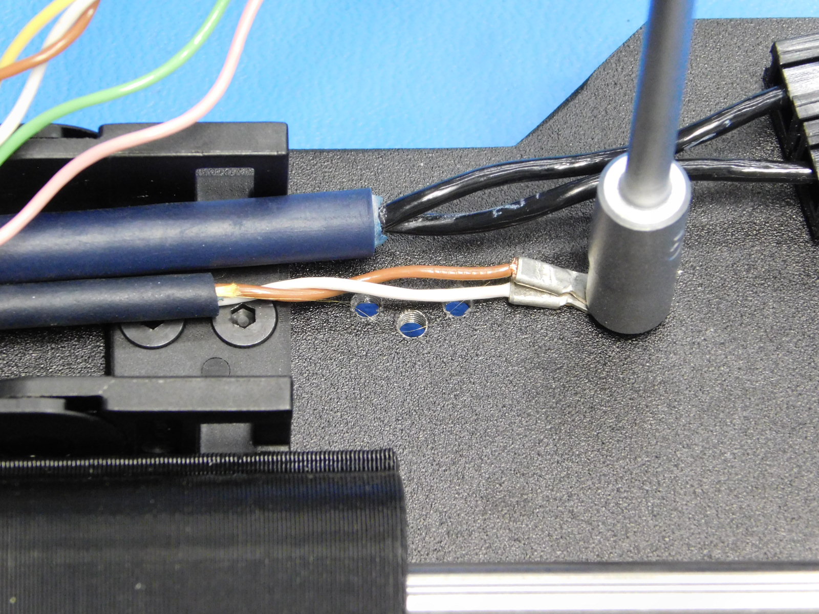
Connect the two ring terminals from the cable harness to the screw, Secure the ring terminals to the screw with a M3 Nyloc nut [HD-NT0001] tighten until the ring terminals no longer move and the SS screw head remains flush and tight to the bed plate.
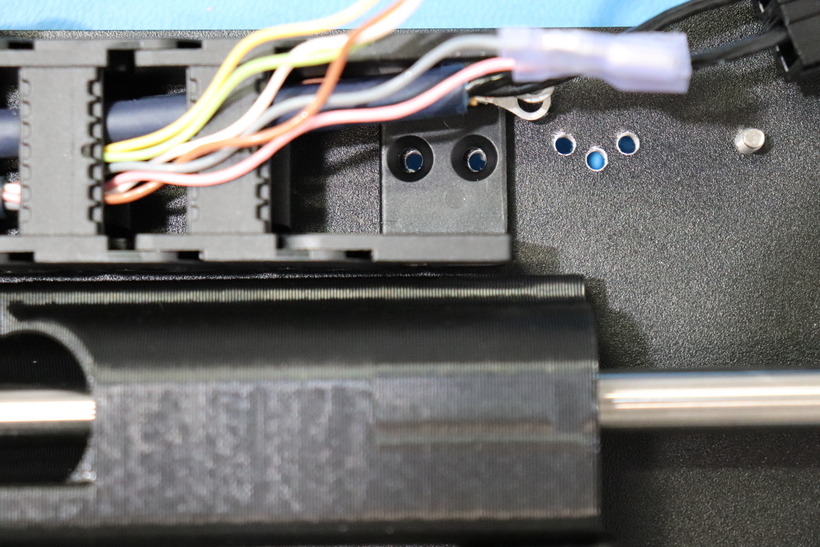
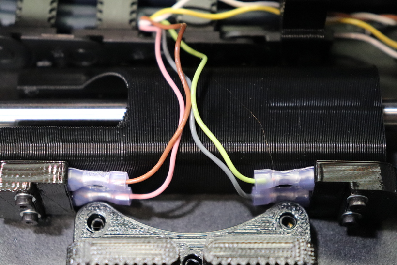
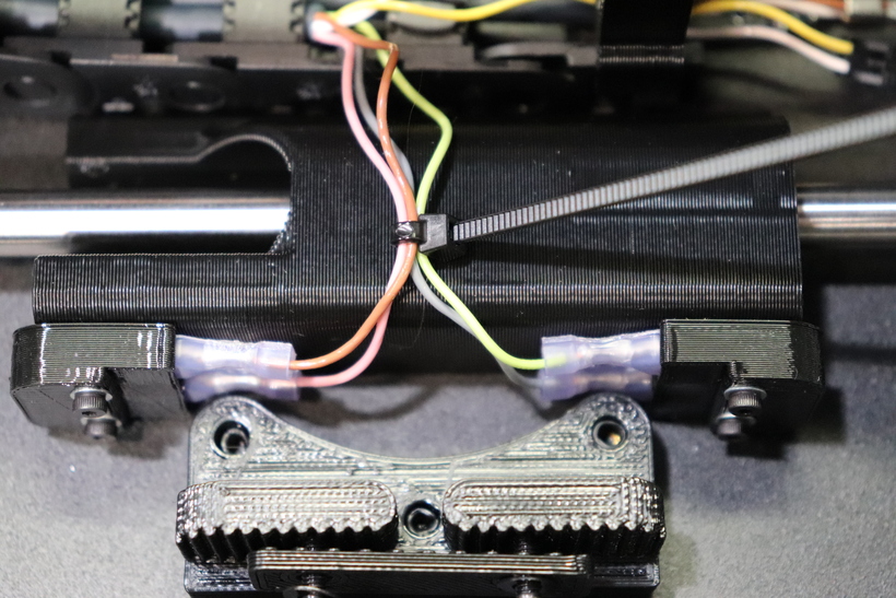
Insert the Green & Gray wires to the pockets on the rear of the Bump Stop on the front (idler side) and the Pink & Brown into the back (motor side) Bump Stop
Tie the two pairs together with a cable tie with the cable tie
Install the bed clip; there is a small notch out of one side of the latch, that notch faces the double bearing holder.
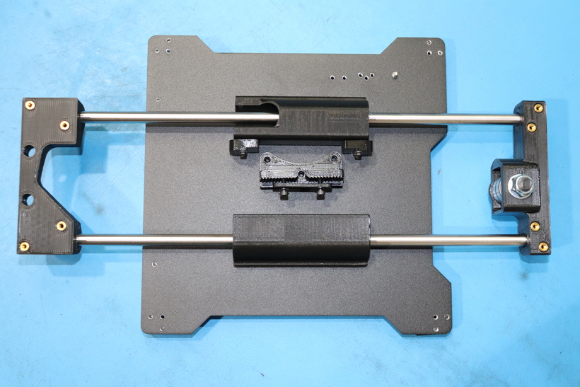
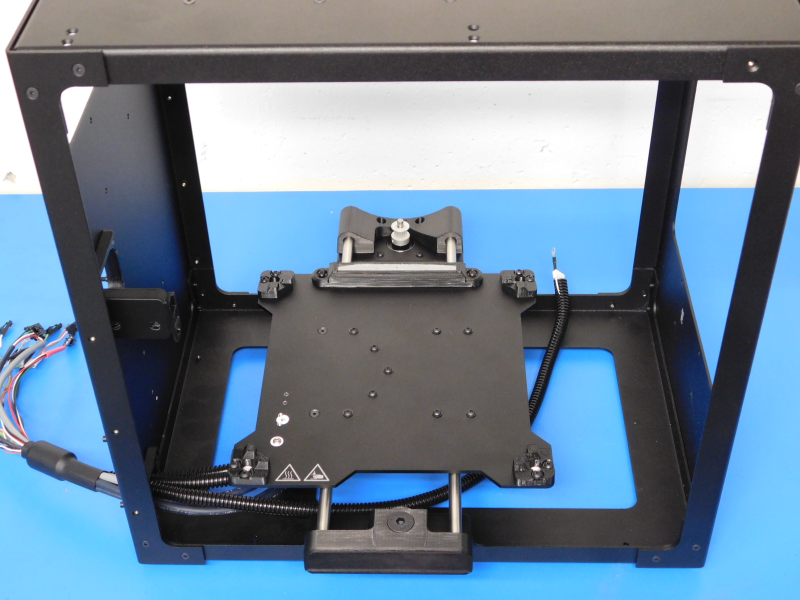
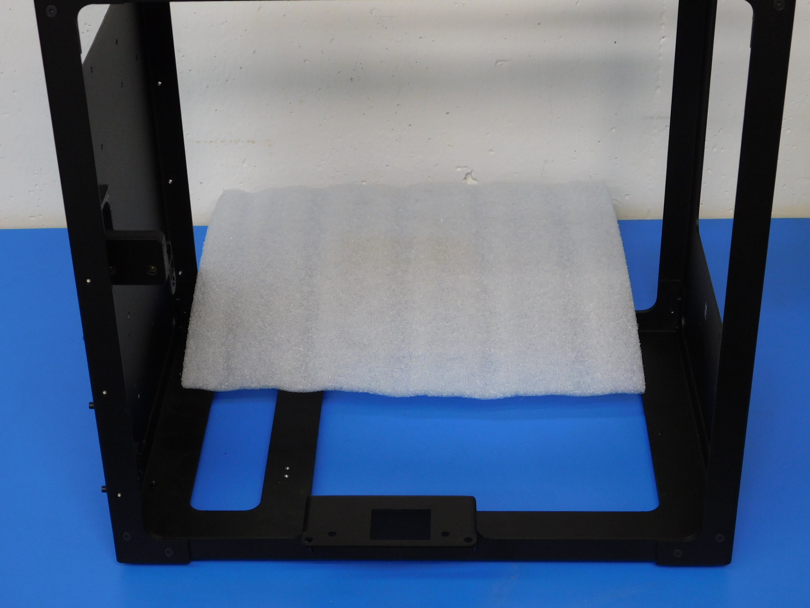
Lay a piece of protective foam over the motor mount of the frame's bottom plate, and place the Bed Plate Assembly face down on top of it with the Rod Mount & Bed Harness end towards you, see [reference#2]
Carefully insert the end of the Bed Harness through the Lower Strain Relief mounted to the Left Frame Plate as pictured
Align the cable chain mount with the two holes in the Bottom Plate and secure using two M3x6 FHCS [HD-BT0128], torque to 5in*lbs
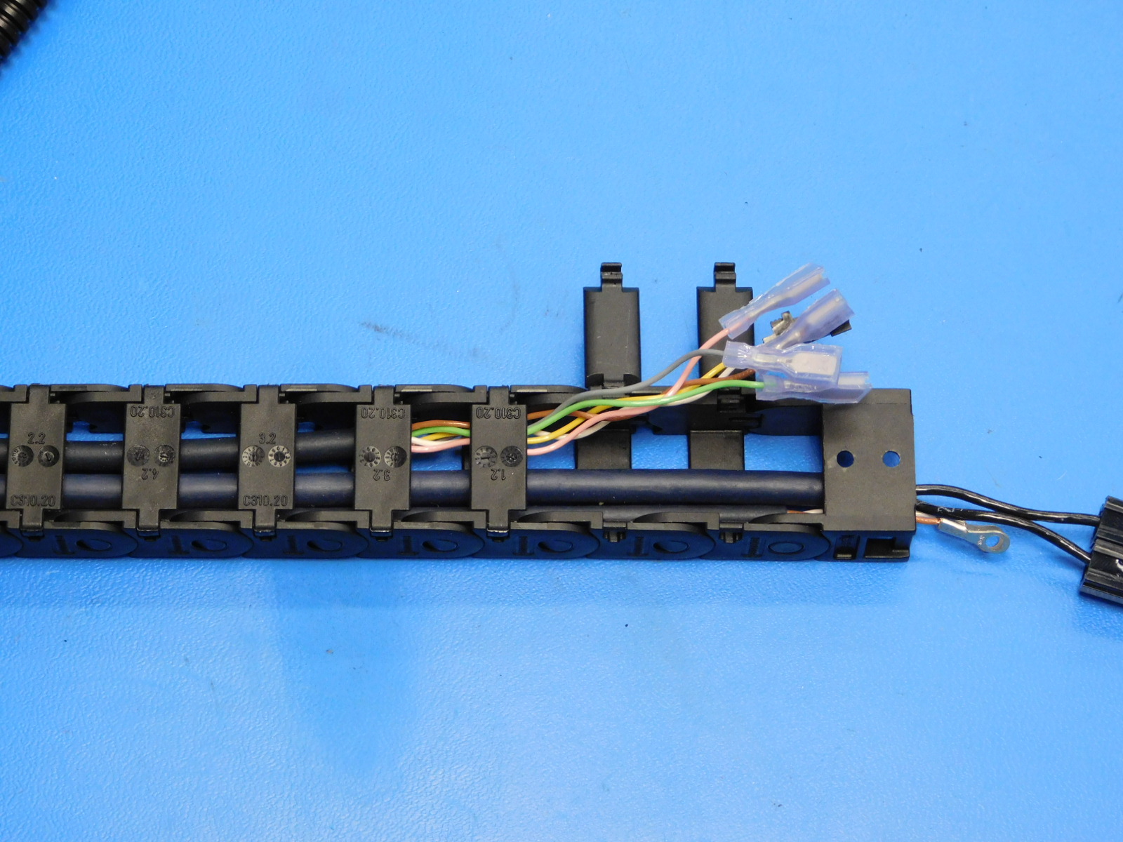
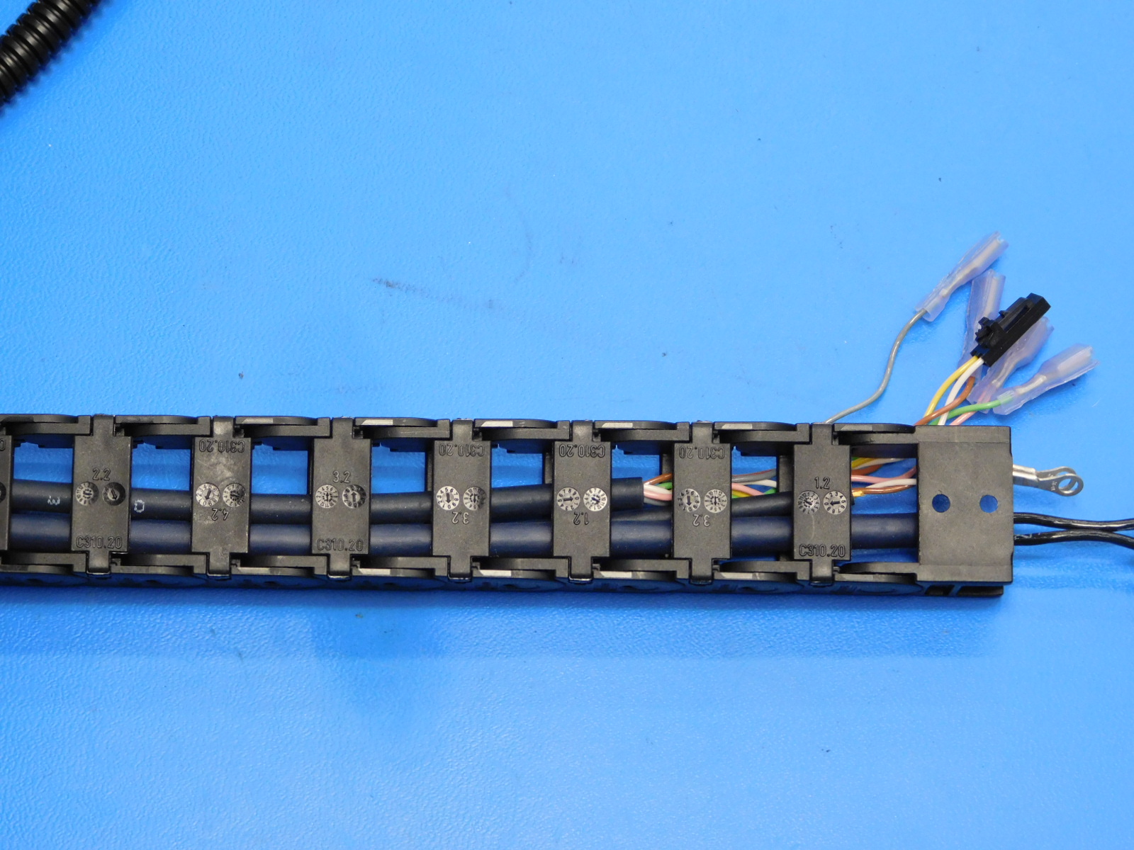
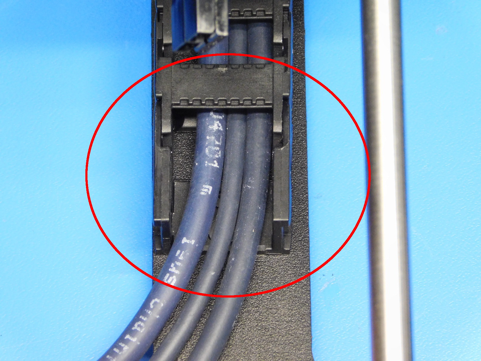
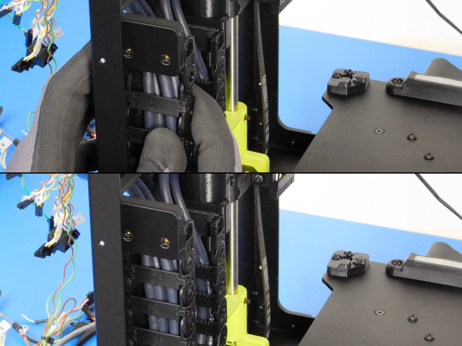
Cables inside of the cable chain must not cross or overlap one another See [reference#3]
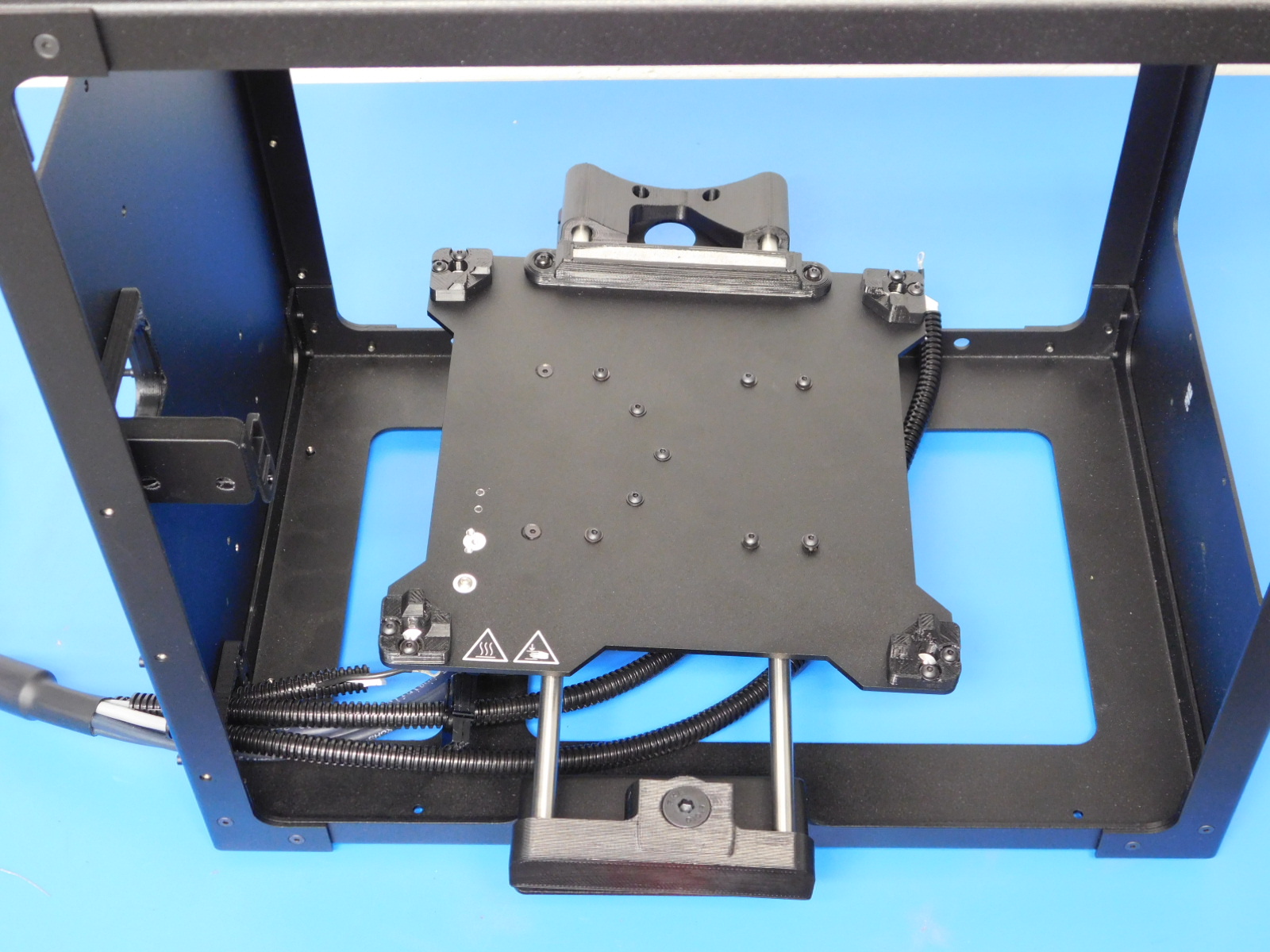
Carefully flip the Bed Plate Assembly into position as shown.
Lean the frame towards the rear (it will rest on the Y-Axis Motor Mount of the Frame)
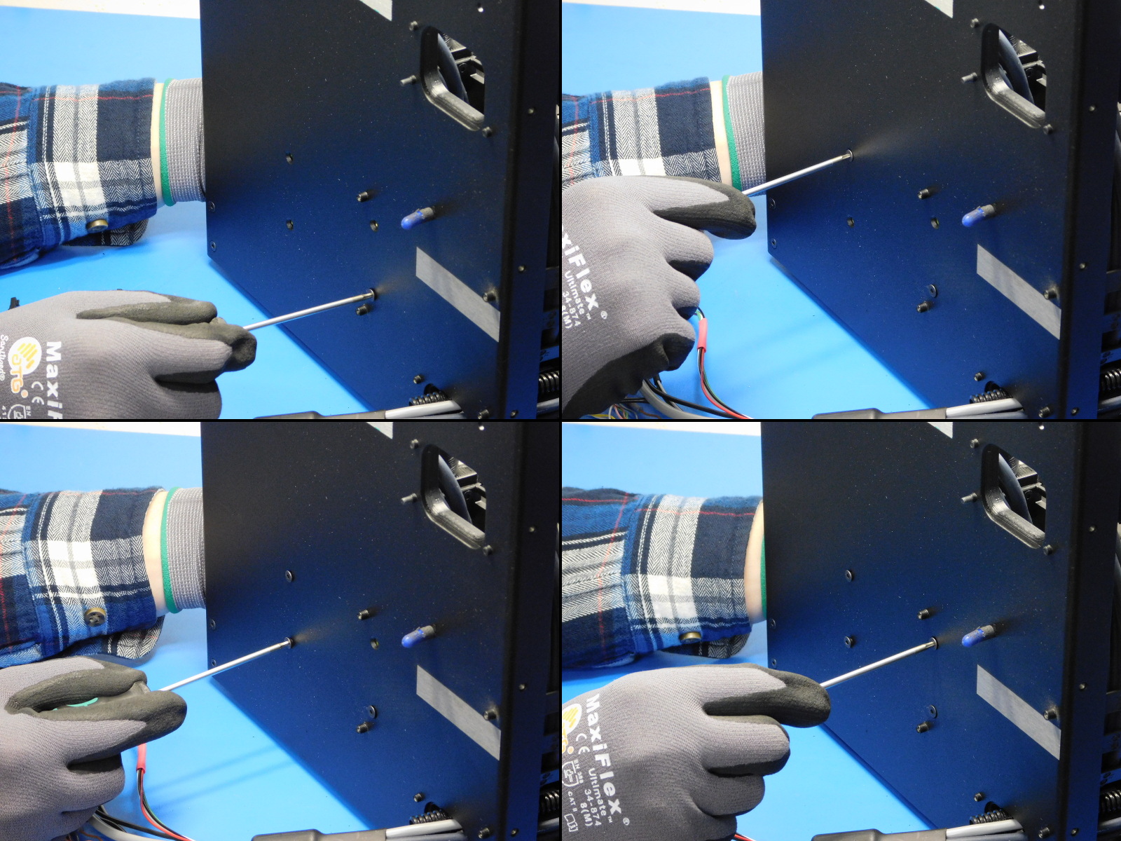
Using 4x M3x8 BHCS [HD-BT0137] with washers [HD-WA0038] secure the Y-Axis Idler to the Bottom Plate
Make sure the front of the Idler printed part remains flush with the idler mount of the Frame. It should be centered between the left and right sides of the mount as well.
Torque fasteners to 5in*lbs
Rotate the frame so that the rear of the frame is facing you.
Lean the frame away from you to expose the screw locations for the Y-Axis Rod Mount
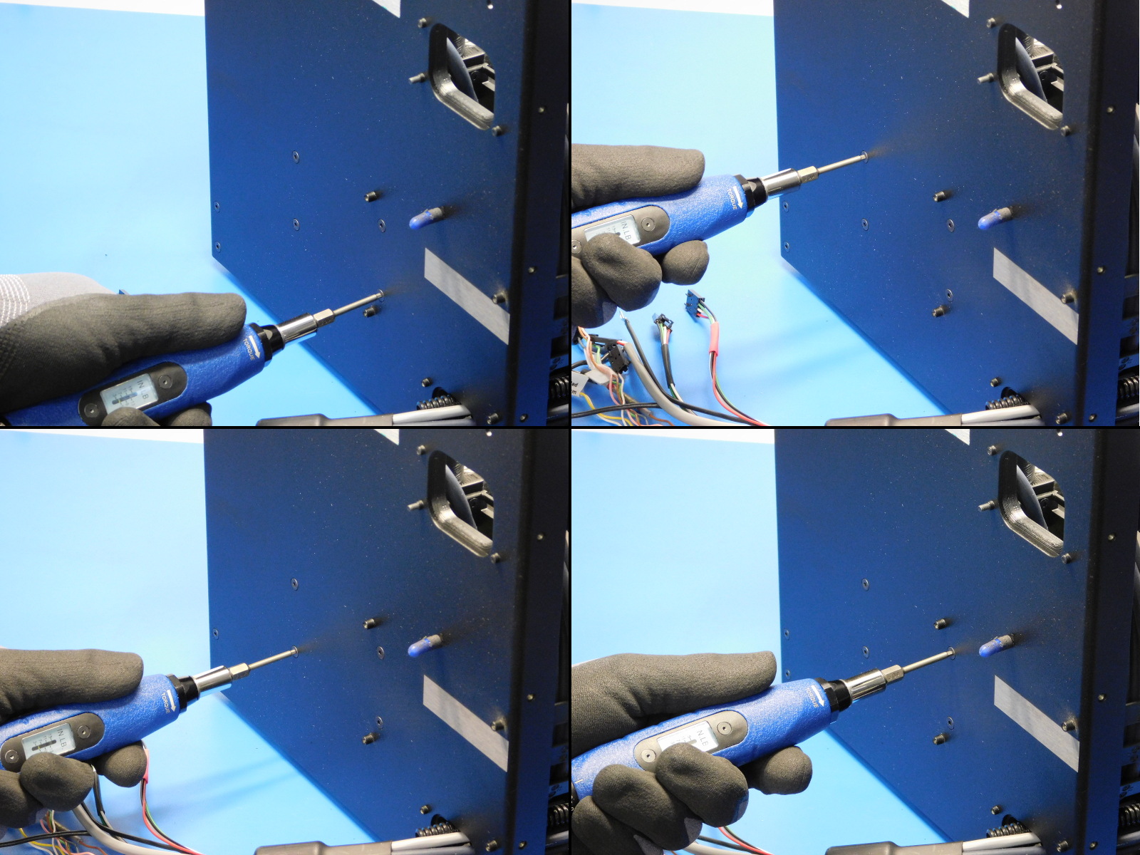
Secure the Y-Rod Mount to the Motor mount flange of the bottom plate using 4x M3x8 BHCS [HD-BT0137] with washers [HD-WA0038]
Make sure the back of the Y-Axis Rod Mount printed part remains flush with the motor mount flange of the Frame. It should be centered between the left and right sides of the mount as well.
Torque fasteners to 5in*lbs
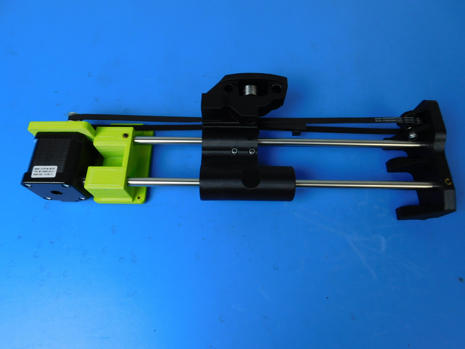
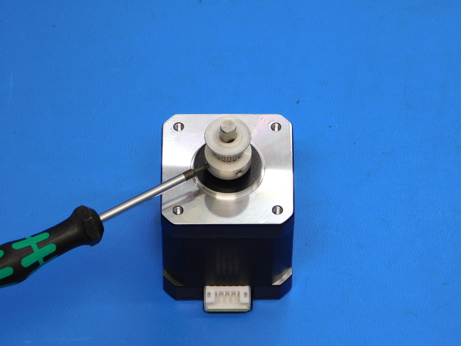
Install a Pulley [HD-MS0033] to the shaft of a Motor [EL-MT0029] using the printed spacer jig to offset the pulley 2mm from the face of the motor.
Align the first set screw to be tightened with the flat side of the motor shaft, tighten both set screws securely.
Align the motor with the Y-Axis Motor mount of the frame with the connector oriented as shown
Secure using 4x M3x6 BHCS [HD-BT0140] with washers [HD-WA0038]
Torque to 5in*lbs
Flip the frame over so that it rests on the top plate.
Route the Y-Axis Motor lead through the hole in the rear of the bottom plate.
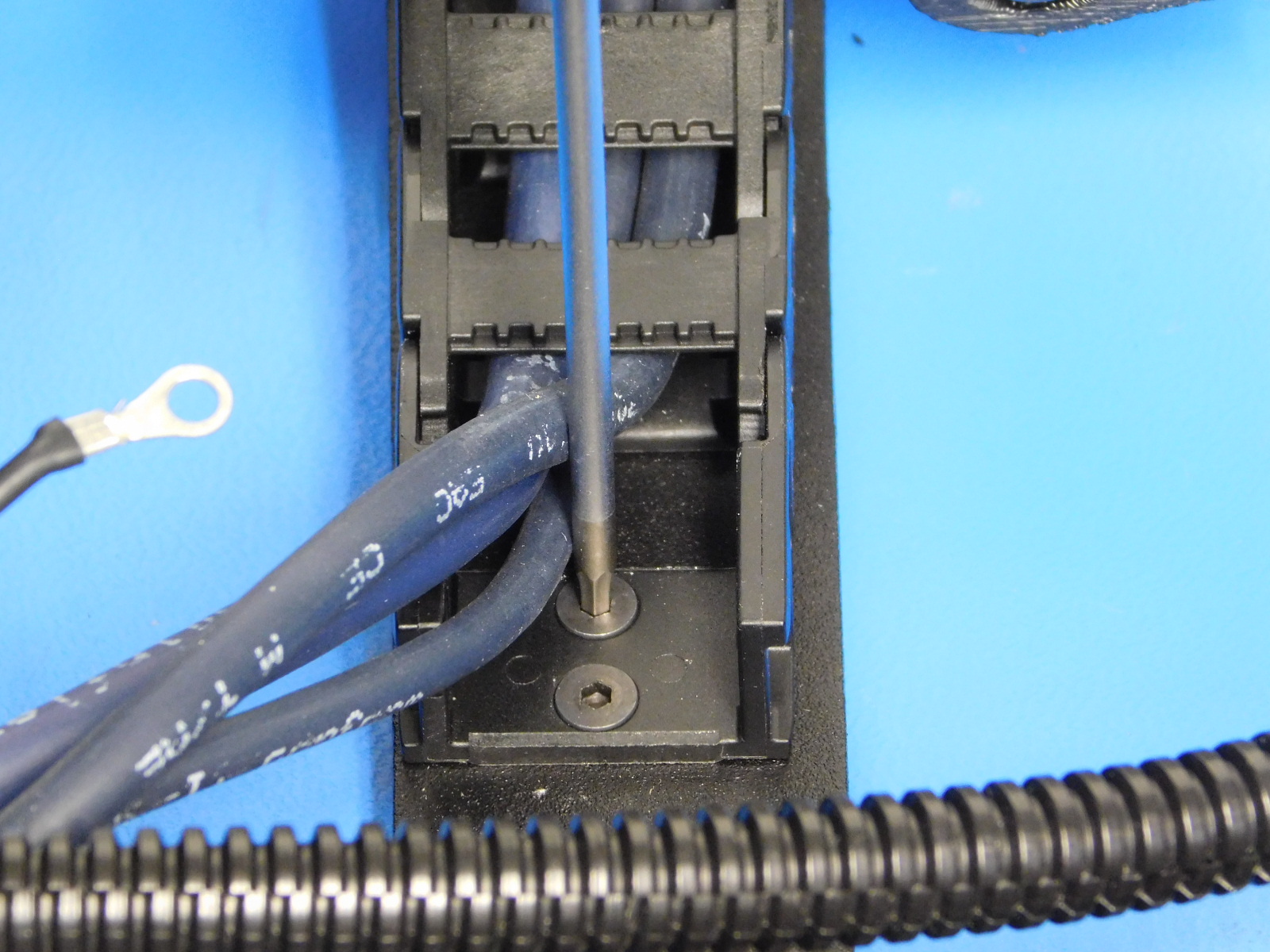
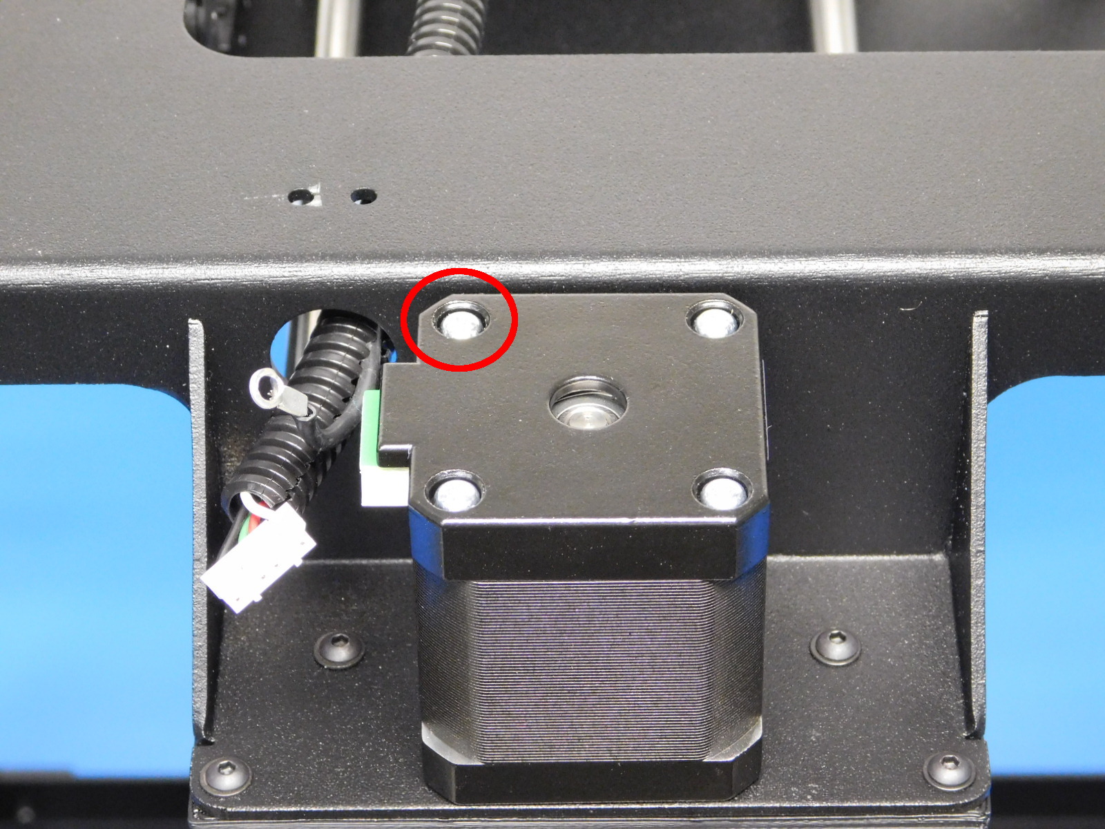
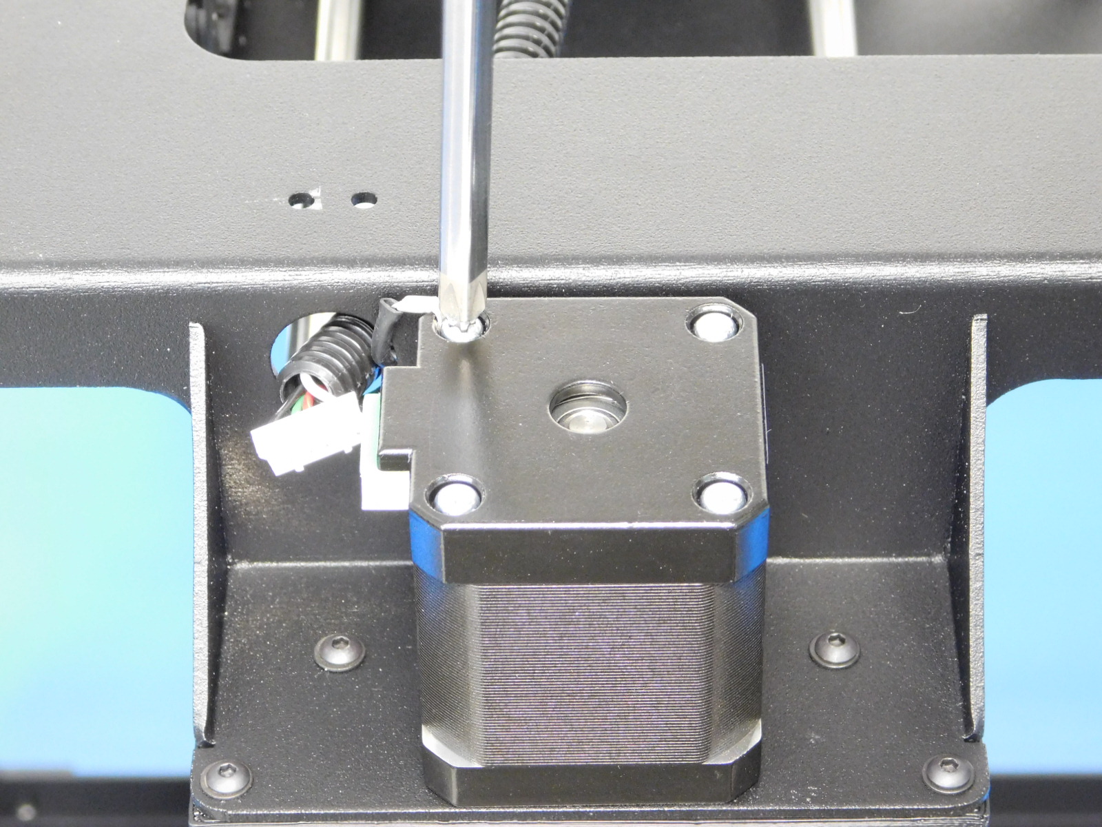
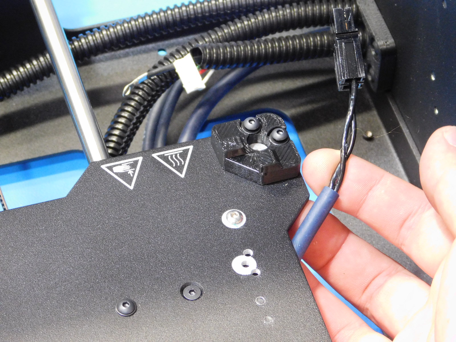
Remove the phillips head screw from the bottom of the motor, closest to the frame and connector [see reference#4]
Install the terminal ring to the screw and re-install the screw, ensuring that it again becomes recessed and tight.
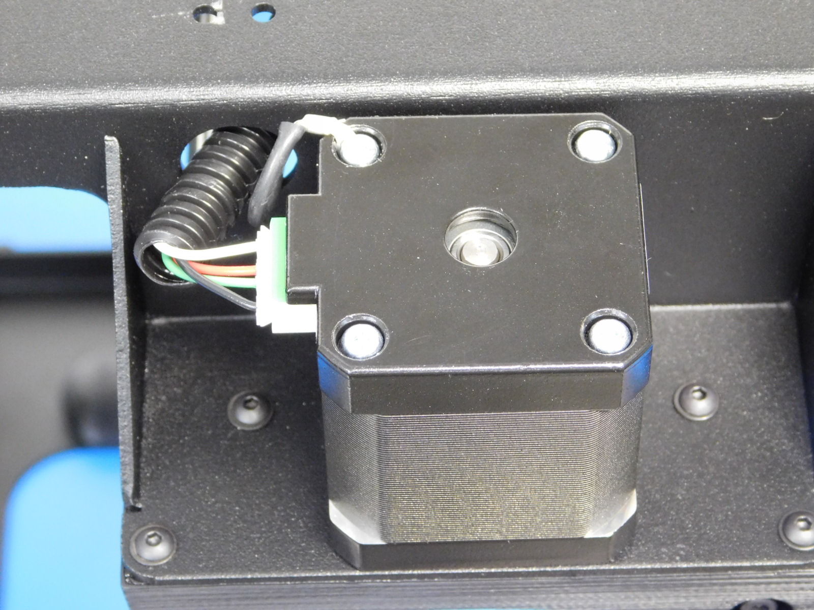
Connect the JST connector to the motor as pictured
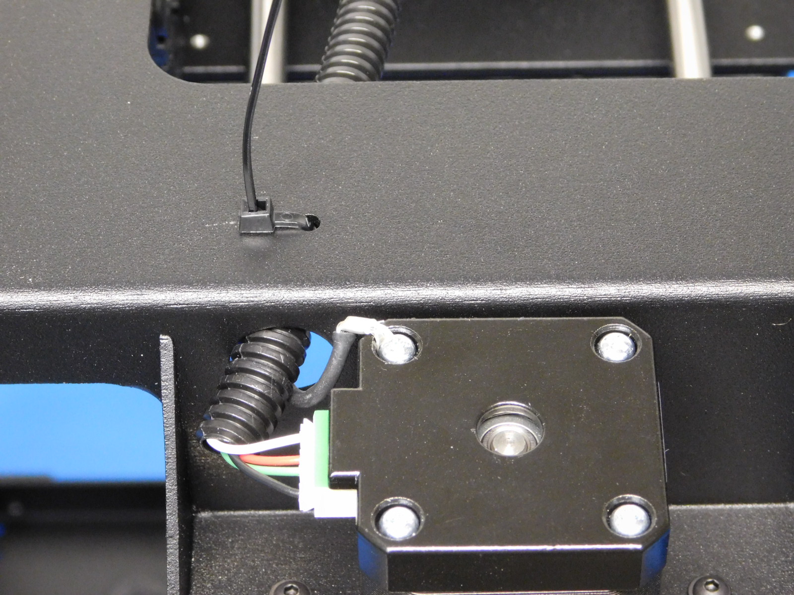
Secure the Y-Axis Motor lead to the frame utilizing the two small holes in the bottom of the frame and a cable tie [HD-MS0058]
The cable tie latch must be on the bottom of the frame.

Flip the frame back upright and rotate if necessary so that the Y-Axis Idler is facing you.
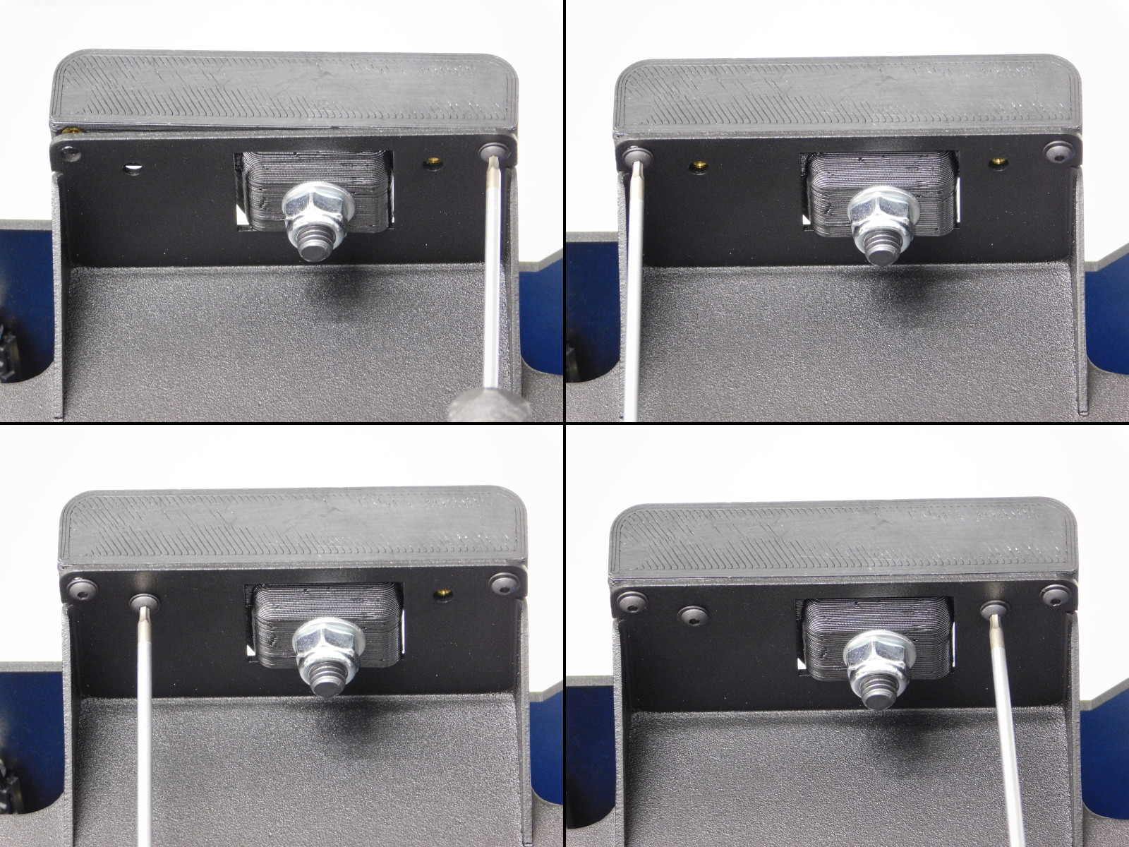
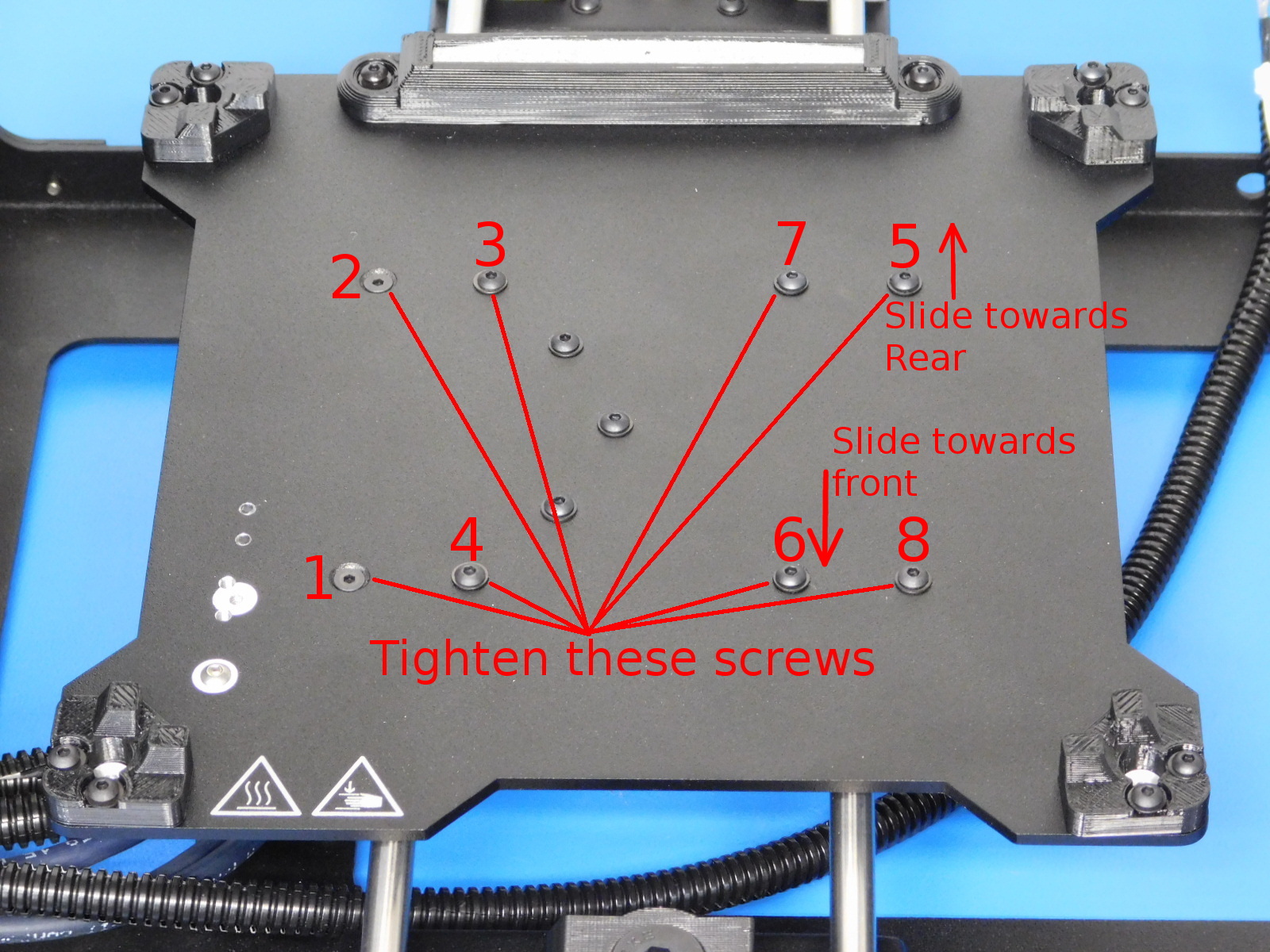
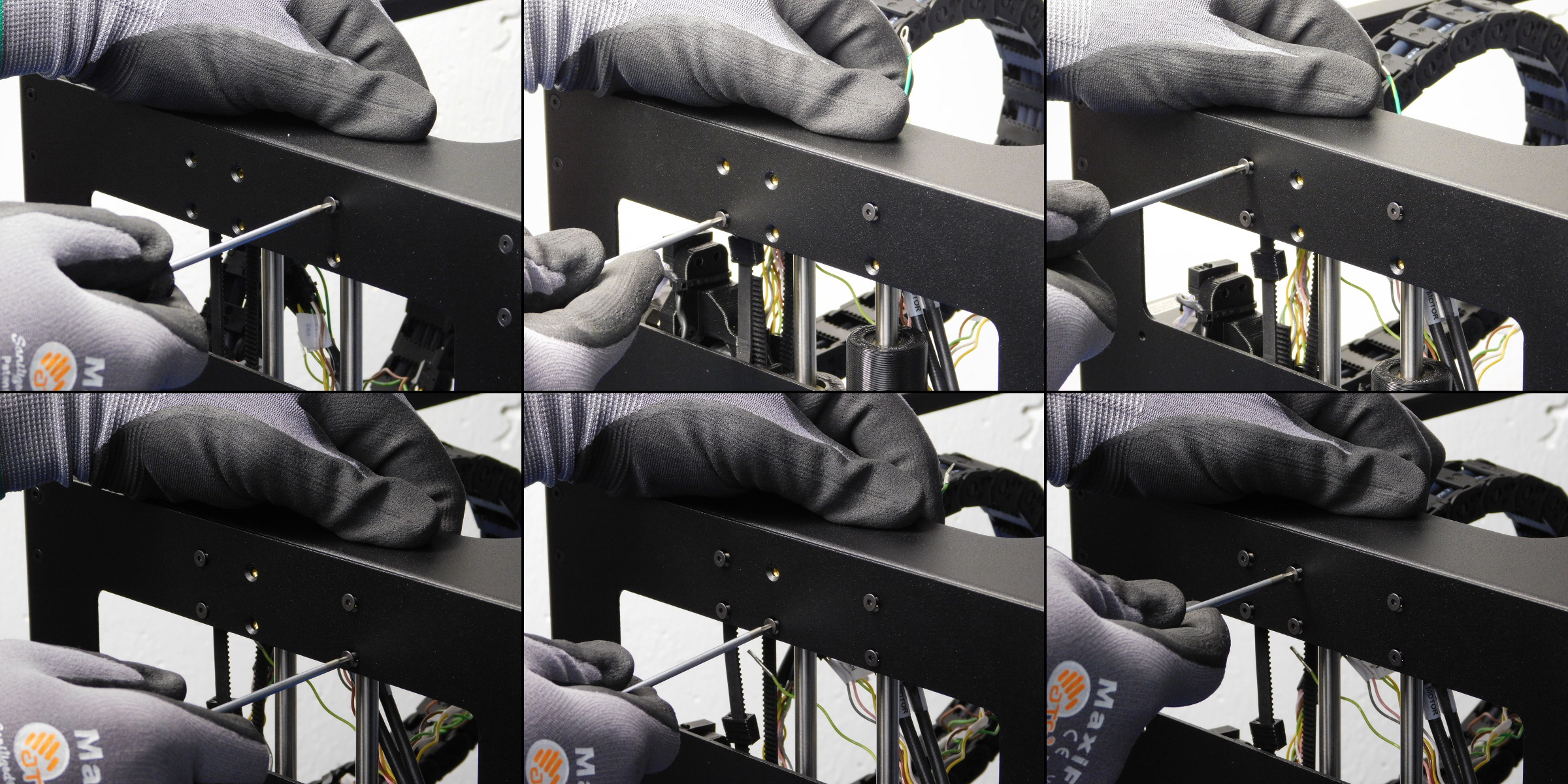
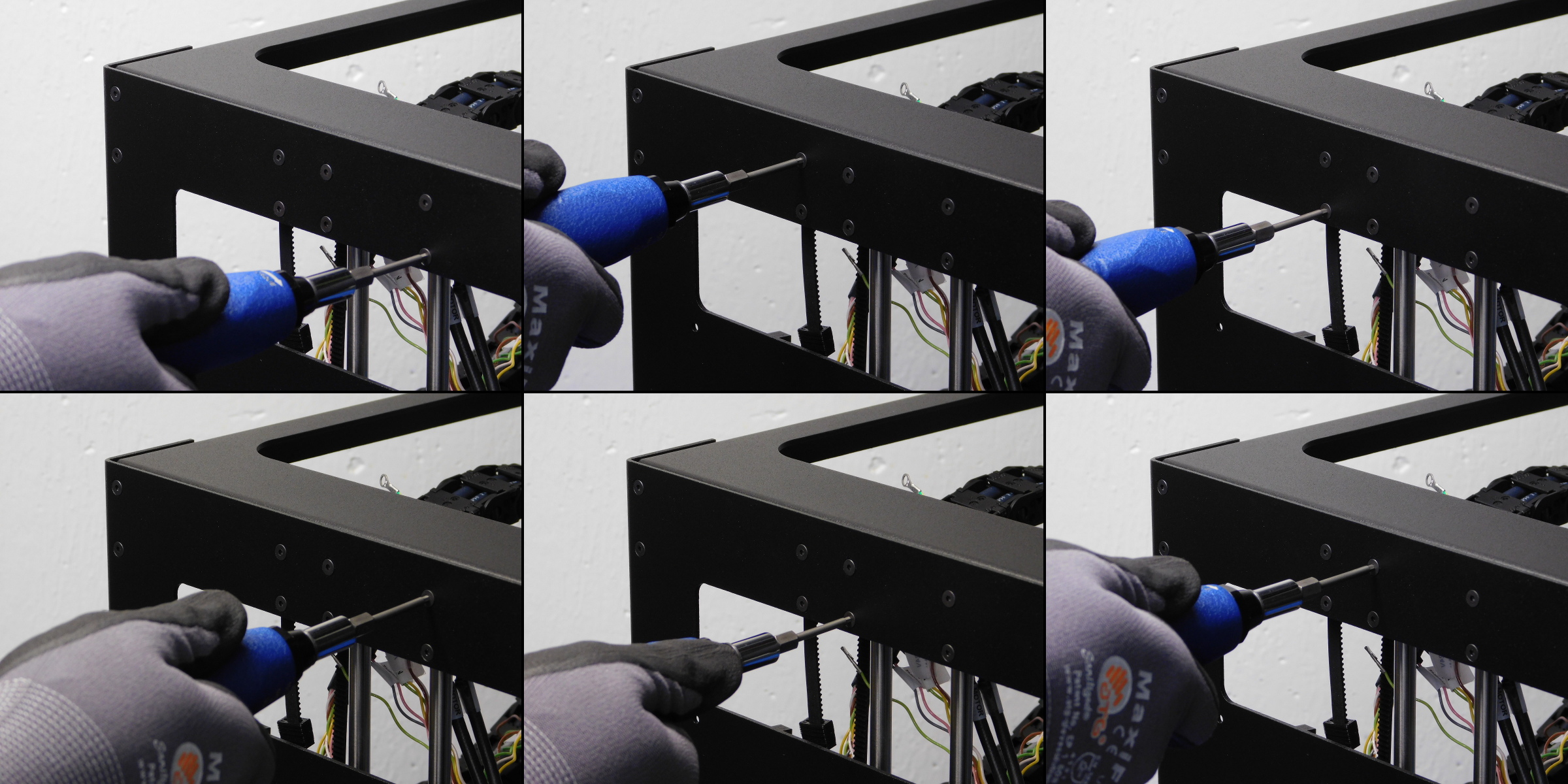
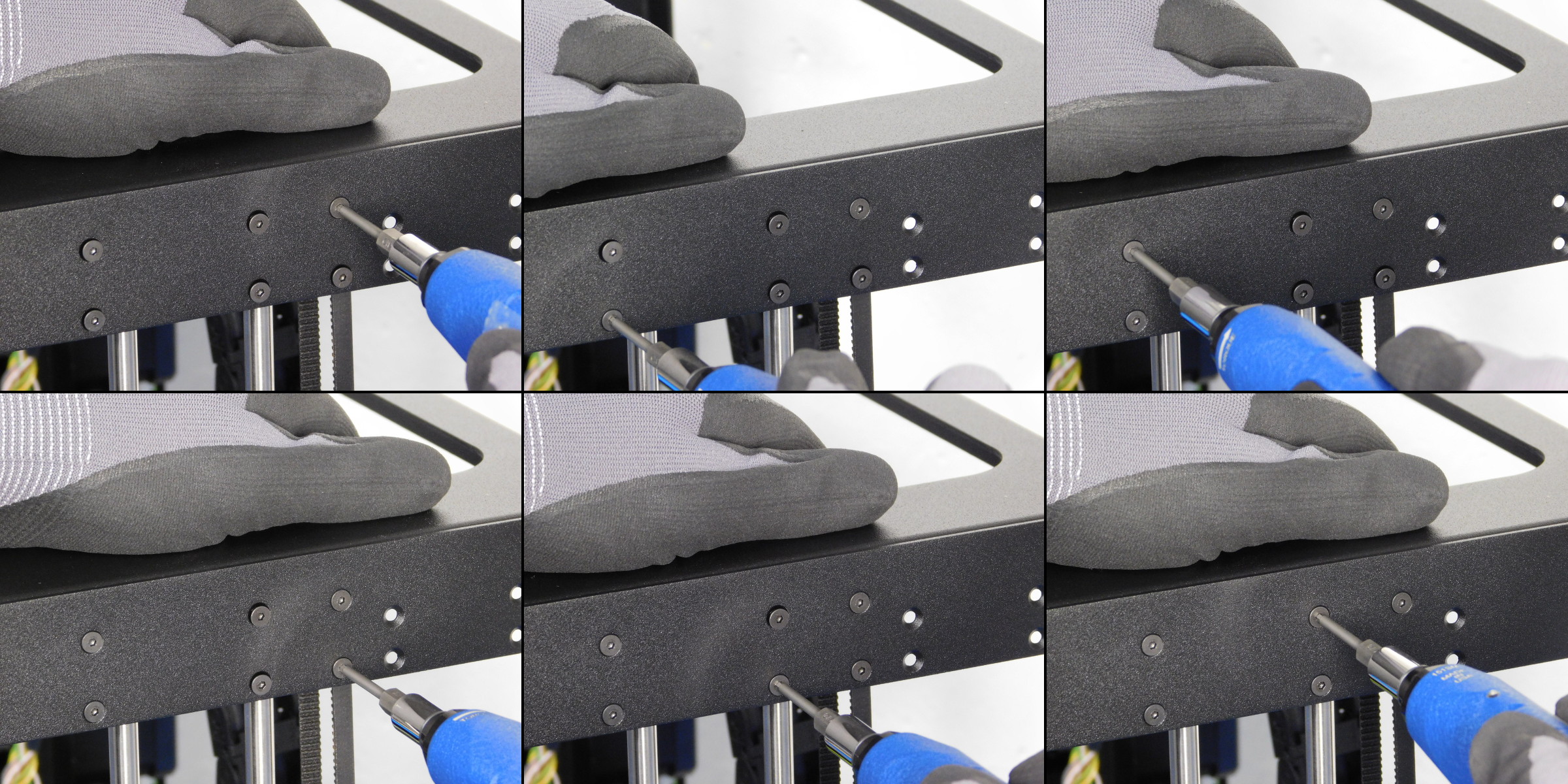
Using a 2mm hex driver, tighten the double bearing holders to the Bed Plate, beginning with the left two flat head screws (1 & 2)
Then tighten the two M3x8 BHCS directly to the right of the two flat head screws (3 & 4)
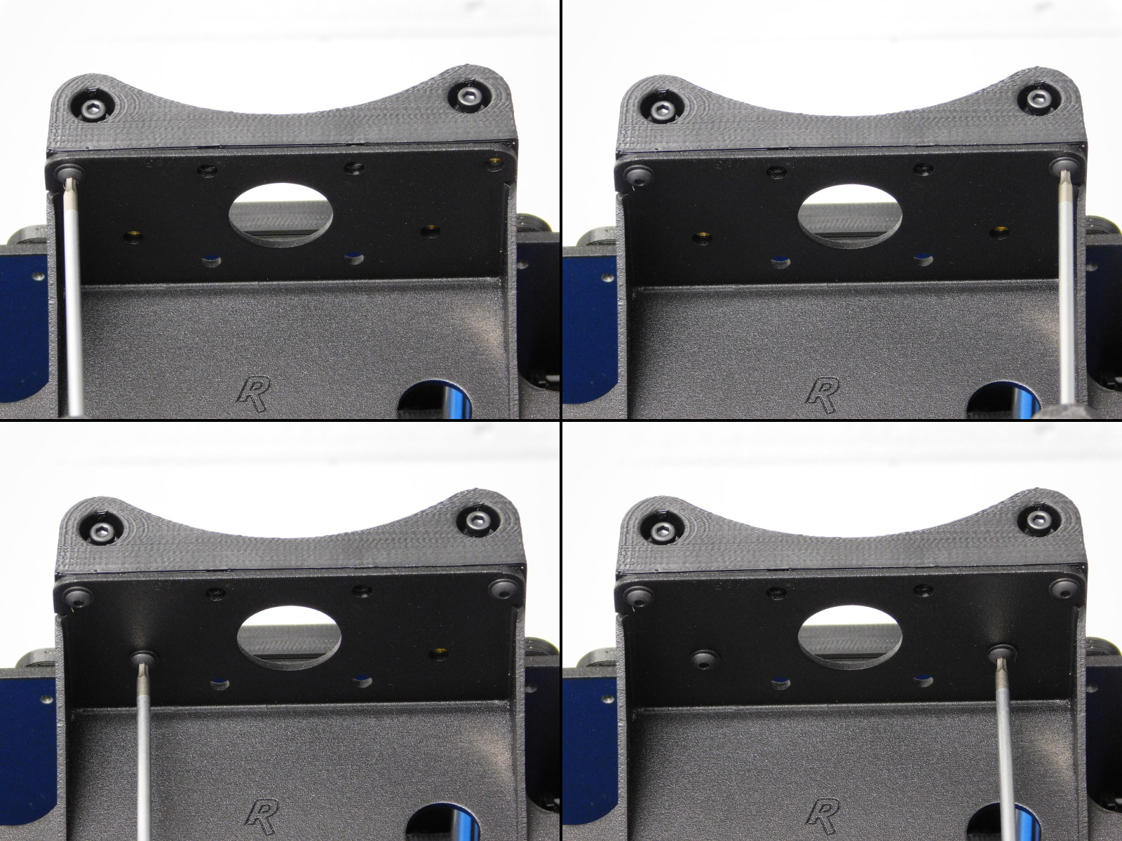
Slide the bed towards the rear and tighten the back right M3x8 BHCS securing the right double bearing holder to the bed plate (5)
Slide the bed towards you and tighten the front left M3x8 BHCS securing the right double bearing holder to the bed plate (6)
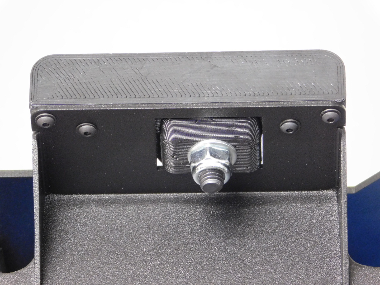
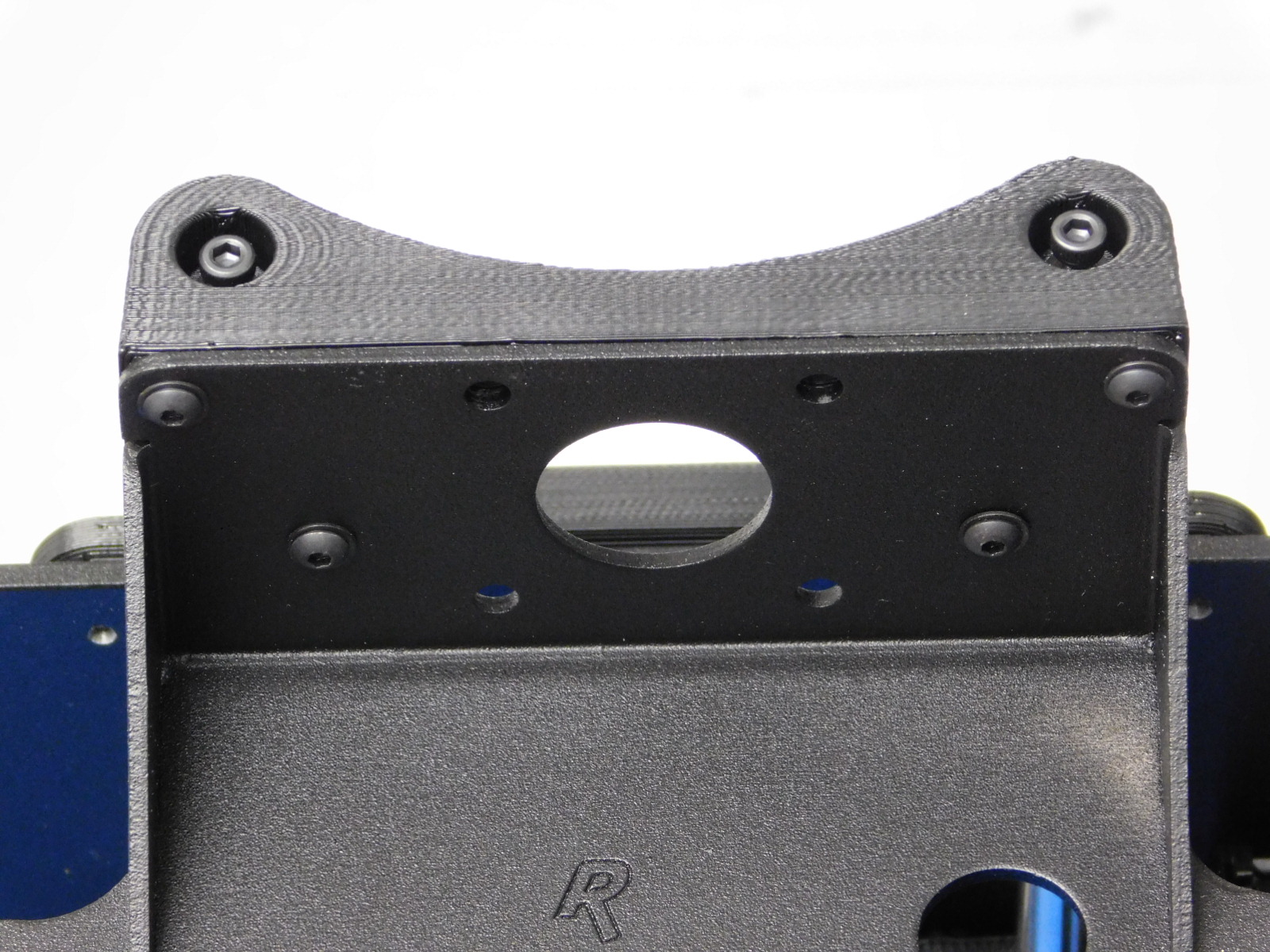
Tighten the remaining two M3x8 BHCS (7 & 8) and torque the six button heads to 3in*lbs and the two flat heads to 5inlbs.
Slide the Bed Plate back and forth and ensure that motion is smooth from end to end without binding.
If stiffness or binding occurs it may be necessary to loosen and re-tighten the bearing holders while moving the Bed Plate, this helps align the bearing holders with the smooth rods.
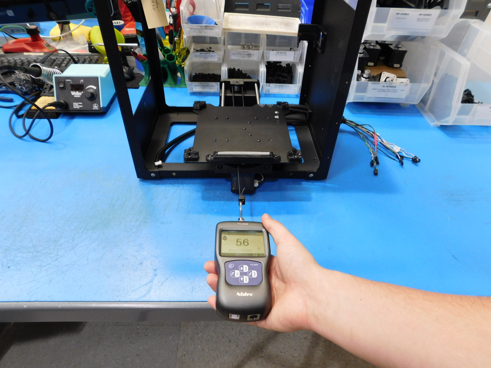
Using the force gauge, measure the carriage drag as shown. If the drag is above 15N, check the individual bushing drags. If needed, carefully broach the bushing set to reduce the drag with the special broaching tool for a maximum of one pass.
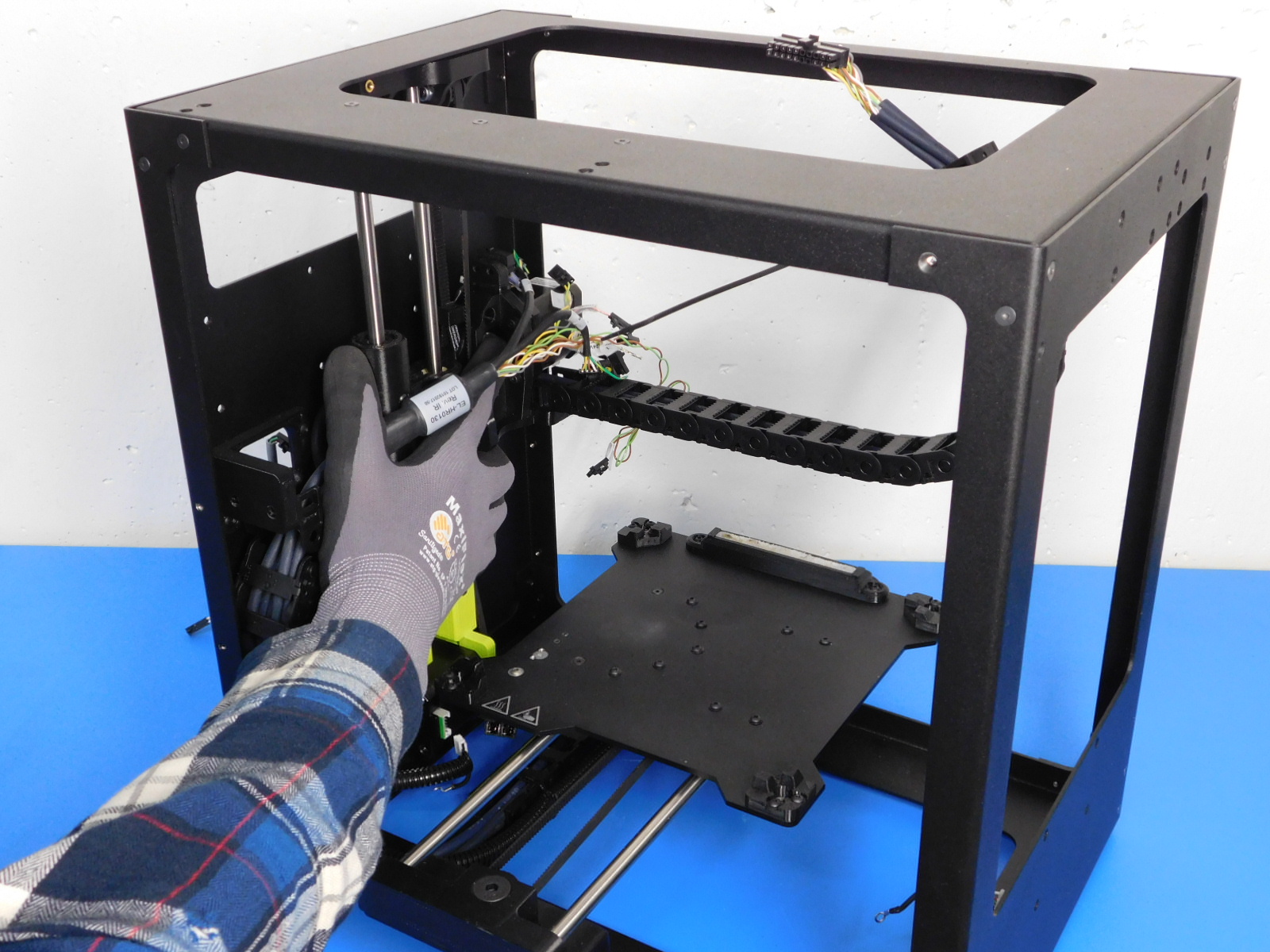
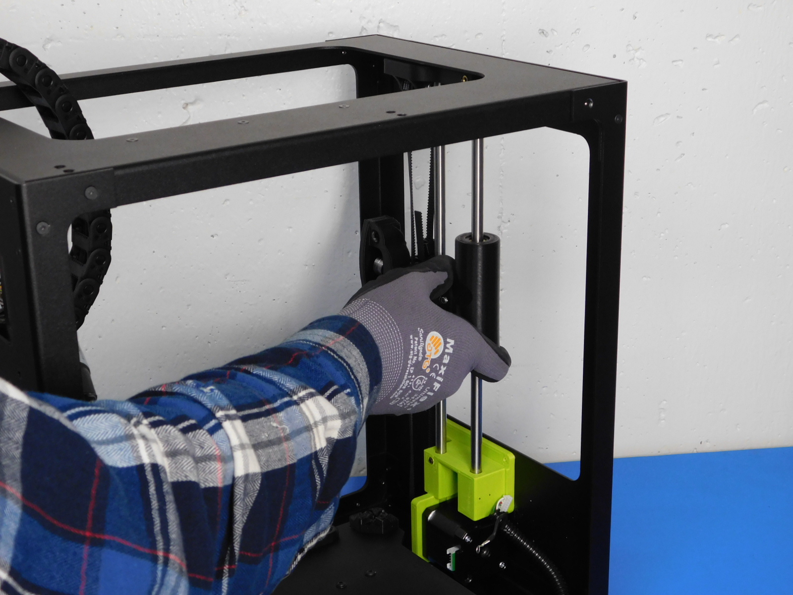
Place the Z Axis left assembly into the frame assembly
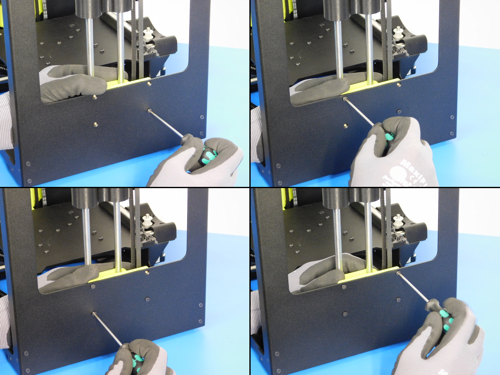
Secure the Z Lower left of the Z Axis left assembly to the frame assembly with four M3 x 6 mm flat-head socket cap screws using a 2.0 mm hex driver, torque to 5 in*lbs
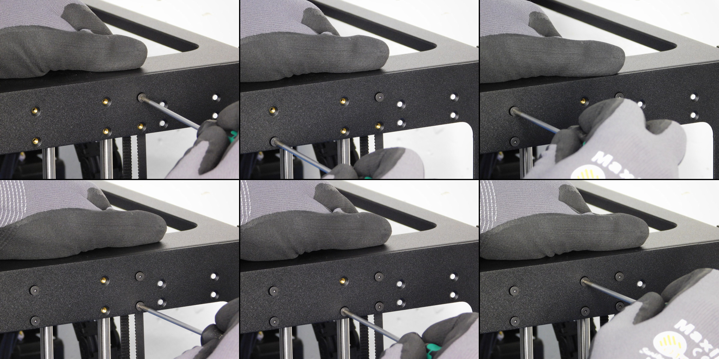
Secure the Z Upper Left of the Z Axis left assembly to the frame assembly with six M3 x 6 mm flat-head socket cap screws using a 2.0 mm hex driver, torque to 5 in*lbs
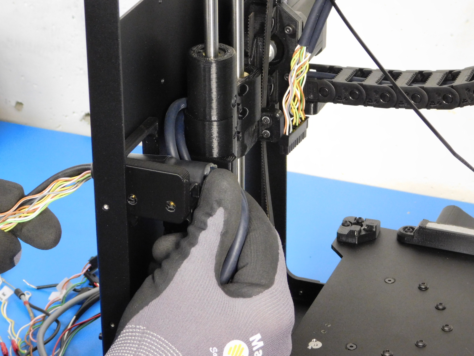
Run the end of the X Harness with the ferrite through the Upper Strain Relief
Attach the X/Extruder Cable harness to the cable chain mount on the Upper Strain Relief
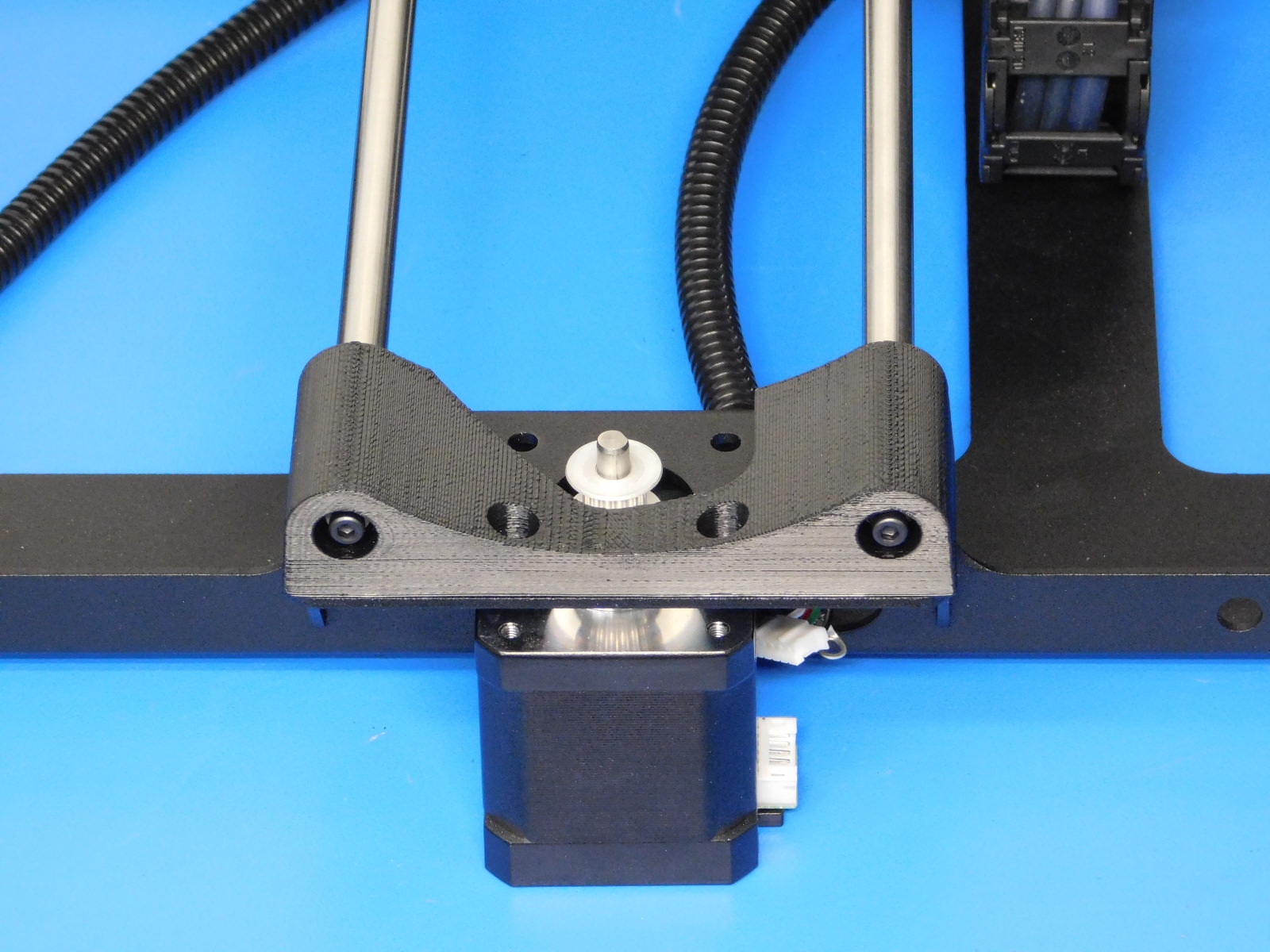
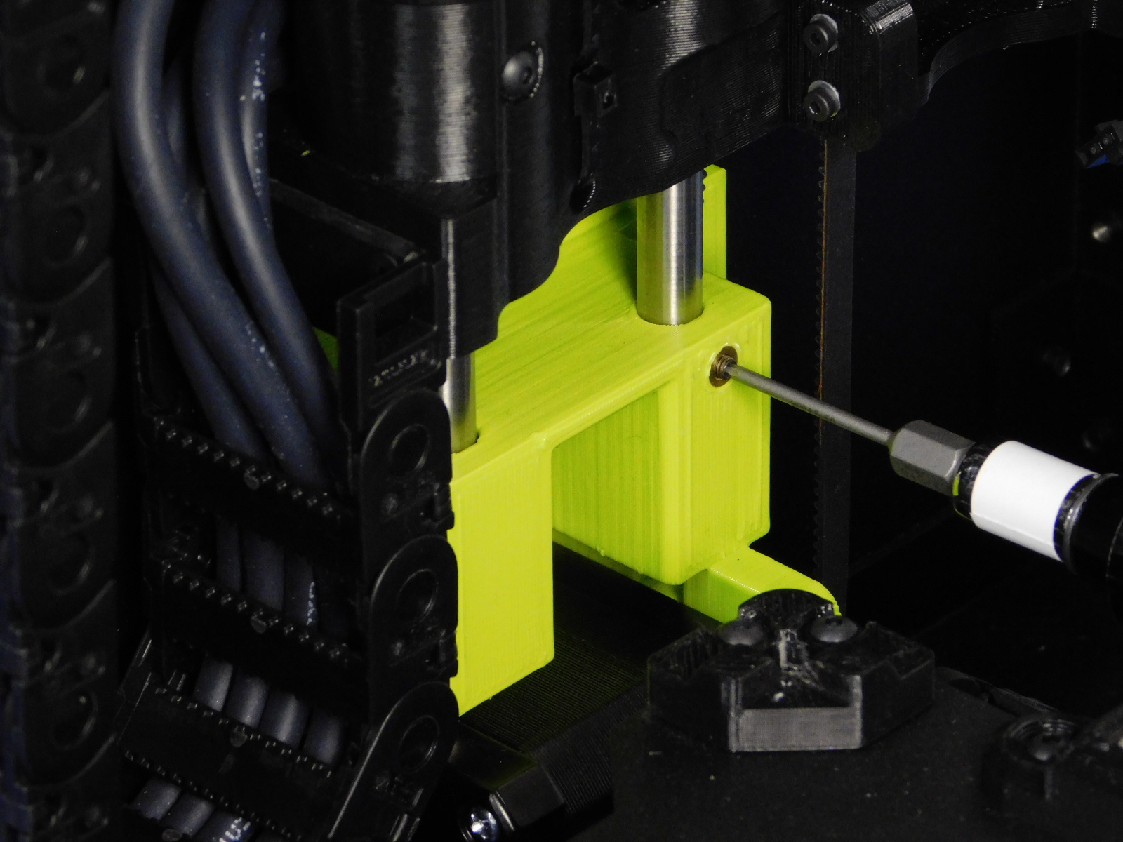
Ensure the Z-Axis Smooth Rods are not making contact with the Z-Motor, this can cause unwanted noise/vibration, there should be a 2-3mm gap between the motor housing and the bottom of the smooth rods.
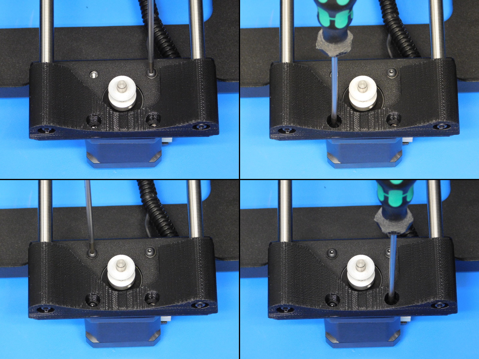
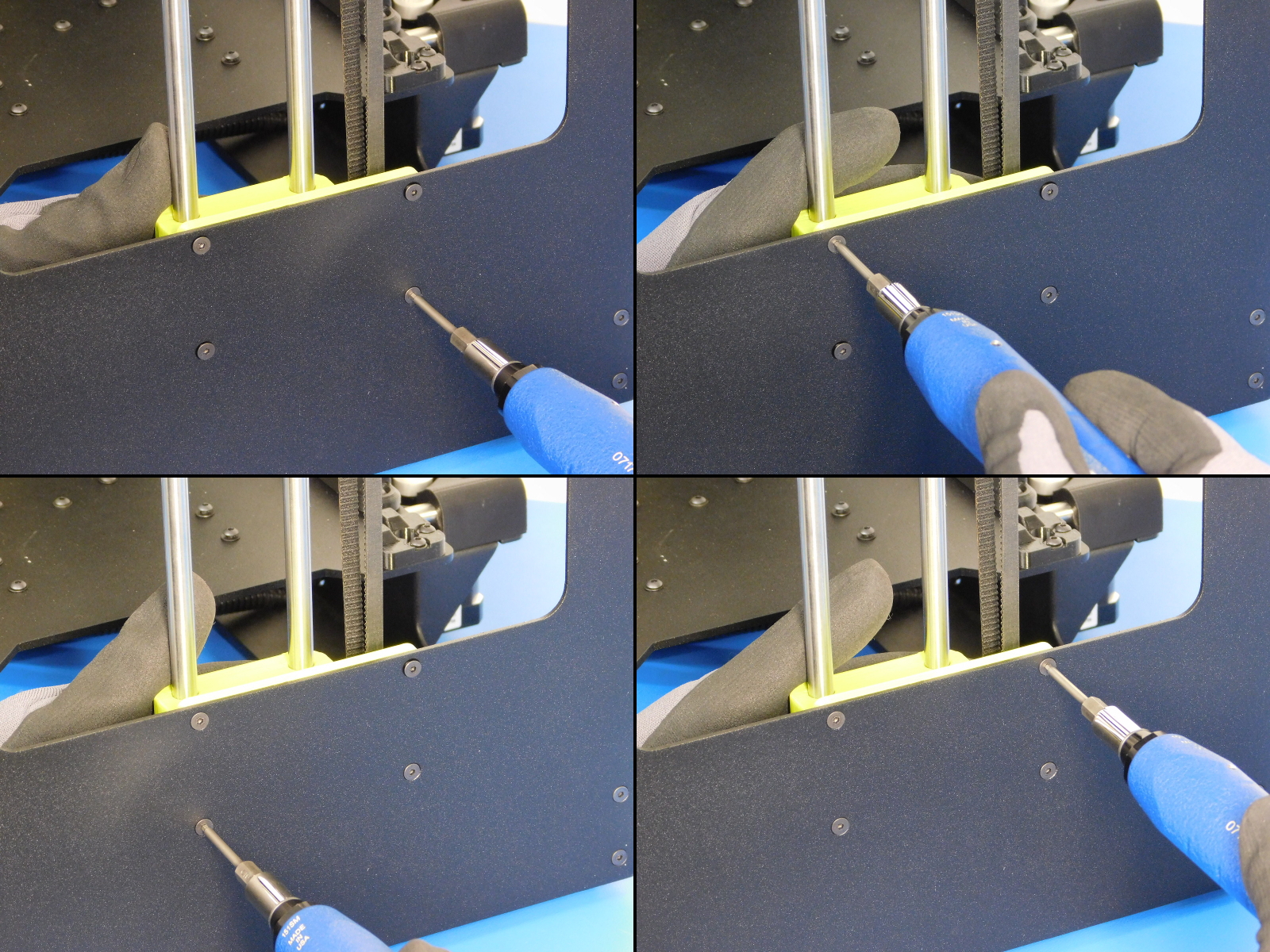
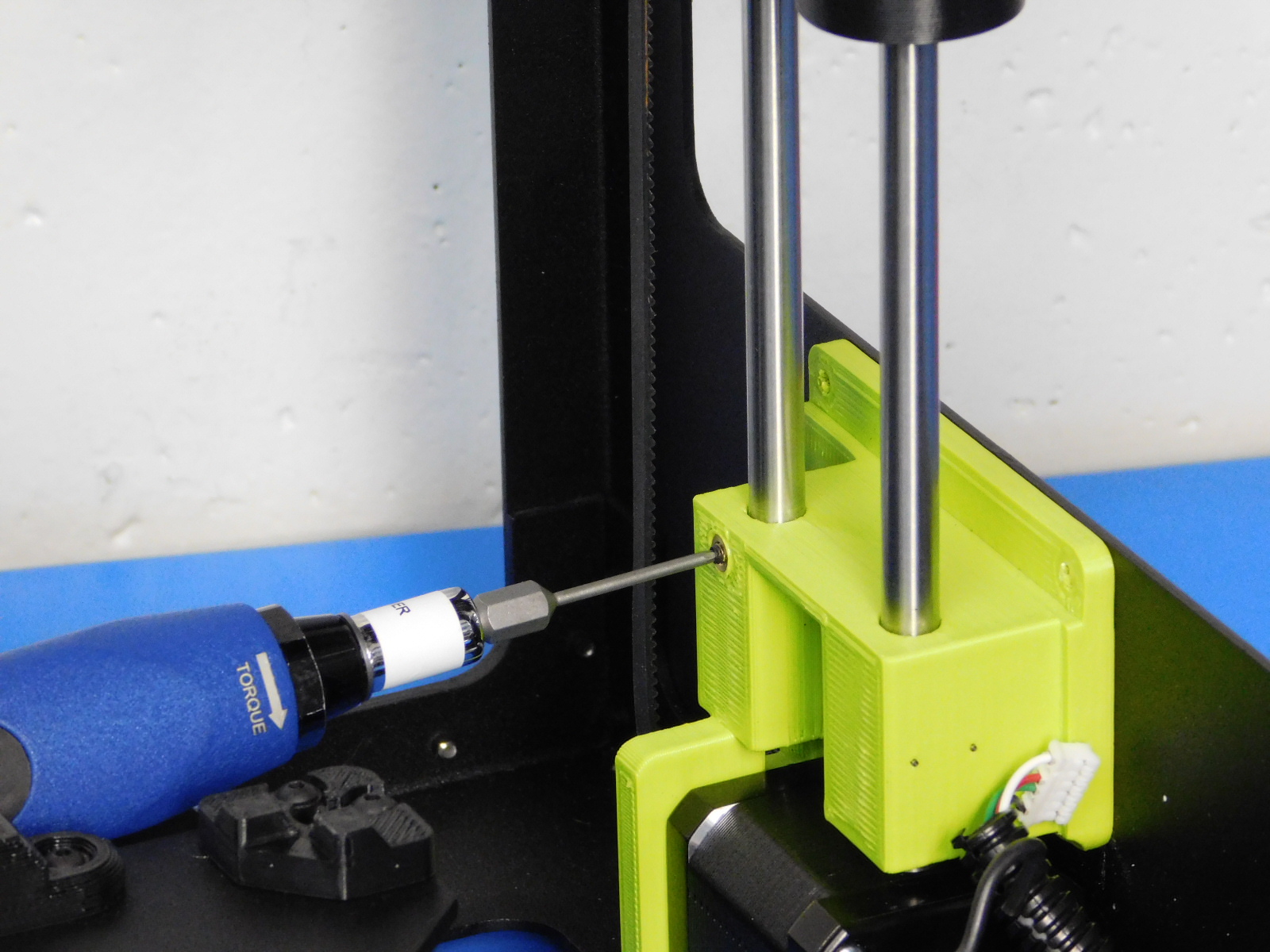
Torque the lower smooth rod set screw to 3in*lbs as pictured.
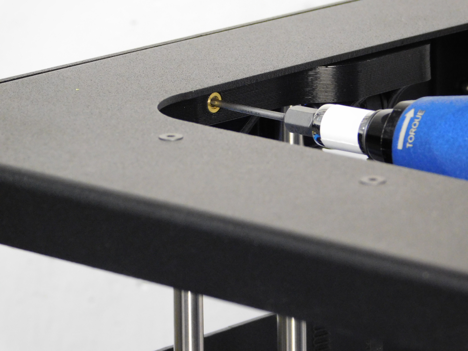
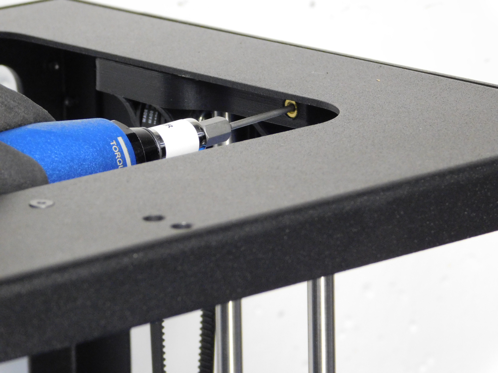
Torque the upper smooth rod set screw to 3in*lbs as pictured.
Place the Z Axis right assembly into the frame assembly
Secure the Z Lower right of the Z Axis right assembly to the frame assembly with four M3 x 6 mm flat-head socket cap screws using a 2.0 mm hex driver, torque to 5 in*lbs
Secure the Z Upper right of the Z Axis right assembly to the frame assembly with six M3 x 6 mm flat-head socket cap screws using a 2.0 mm hex driver, torque to 5 in*lbs
Ensure the Z-Axis Smooth Rods are not making contact with the Z-Motor, this can cause unwanted noise/vibration, there should be a 2-3mm gap between the motor housing and the bottom of the smooth rods.
Torque the lower smooth rod set screw on the Z-Lower to 3in*lbs as pictured
Torque the upper smooth rod set screw on the Z-Upper to 3in*lbs as pictured.
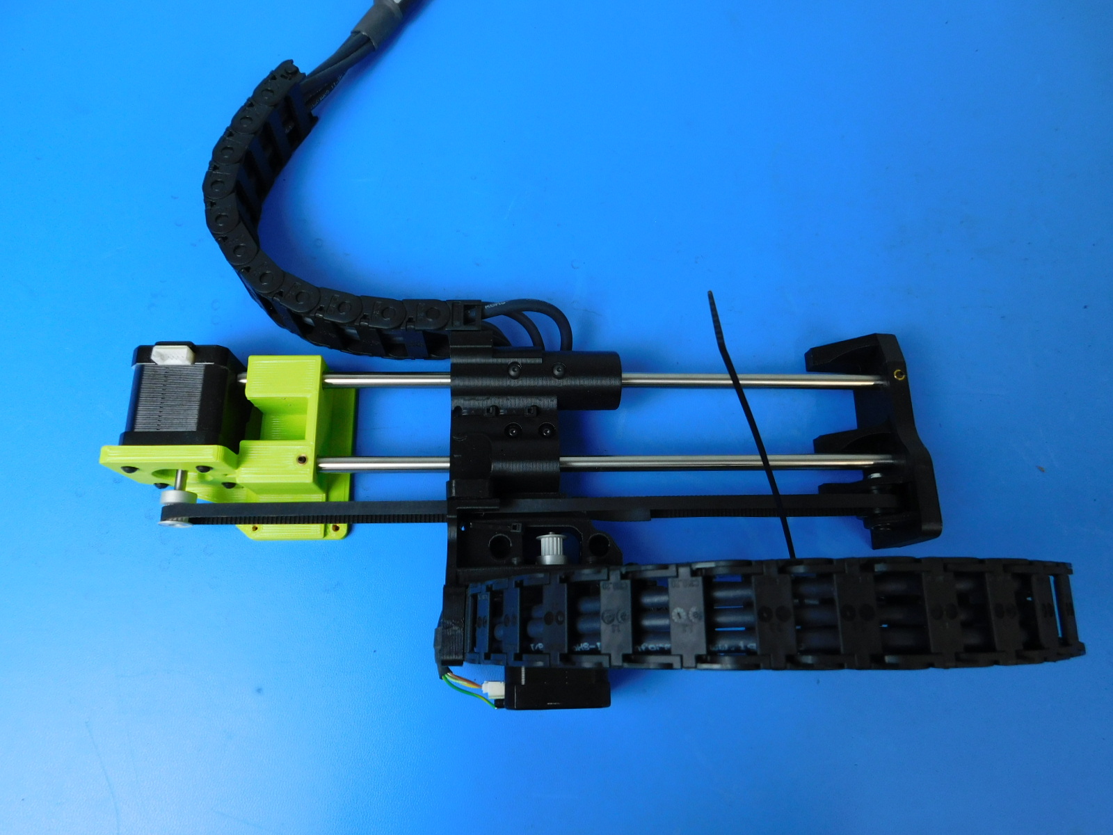
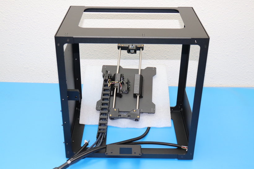
Verify that what you've assembled matches the picture at right.