Open HardwareAssembly Instructions
Guides for installation and assembly of the LulzBot line of products made by Aleph Objects, Inc.
Guides for installation and assembly of the LulzBot line of products made by Aleph Objects, Inc.
a.)
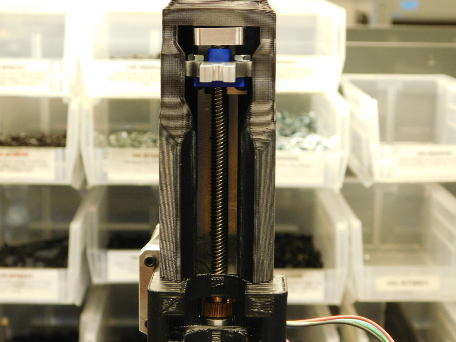
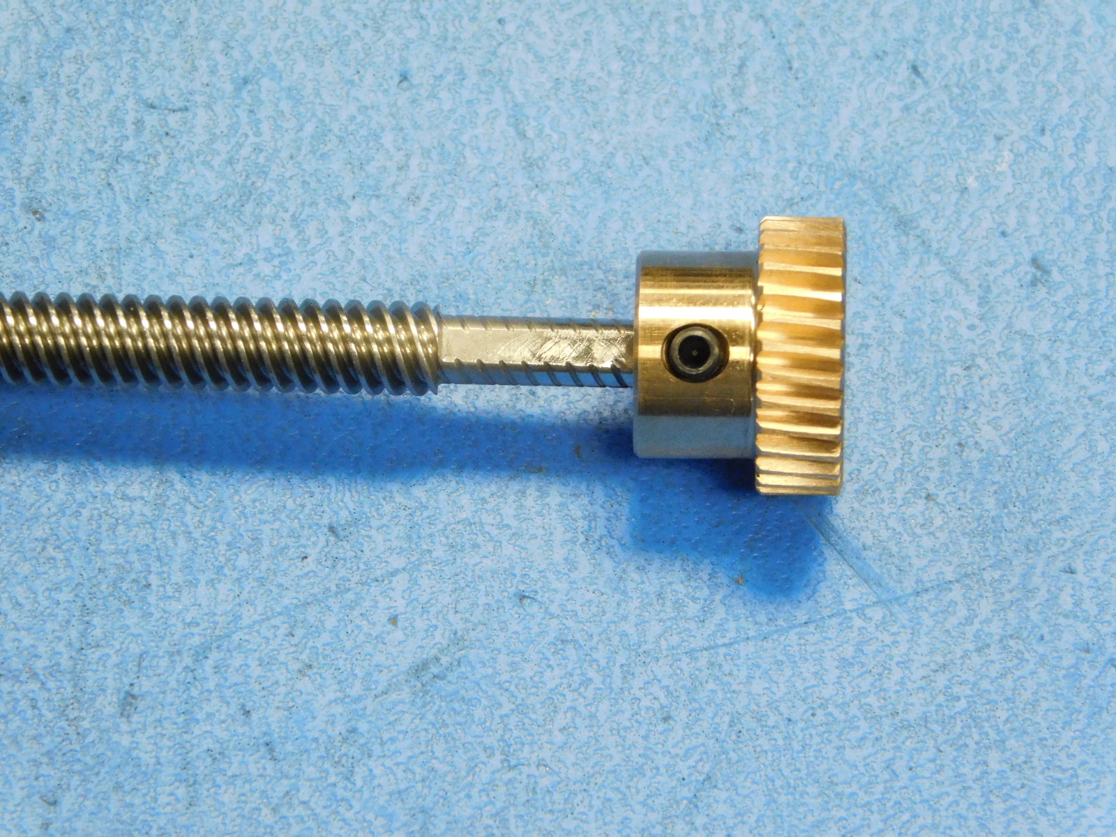
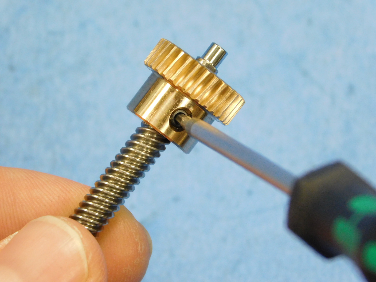
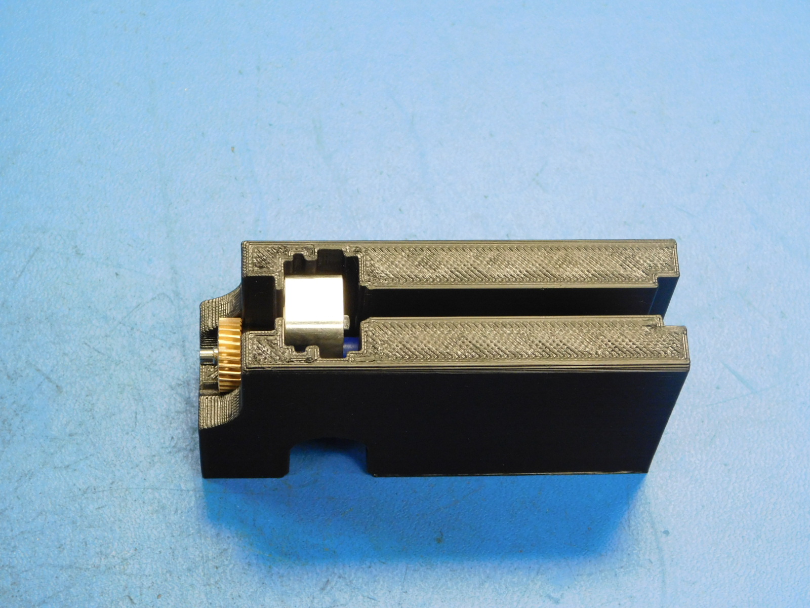
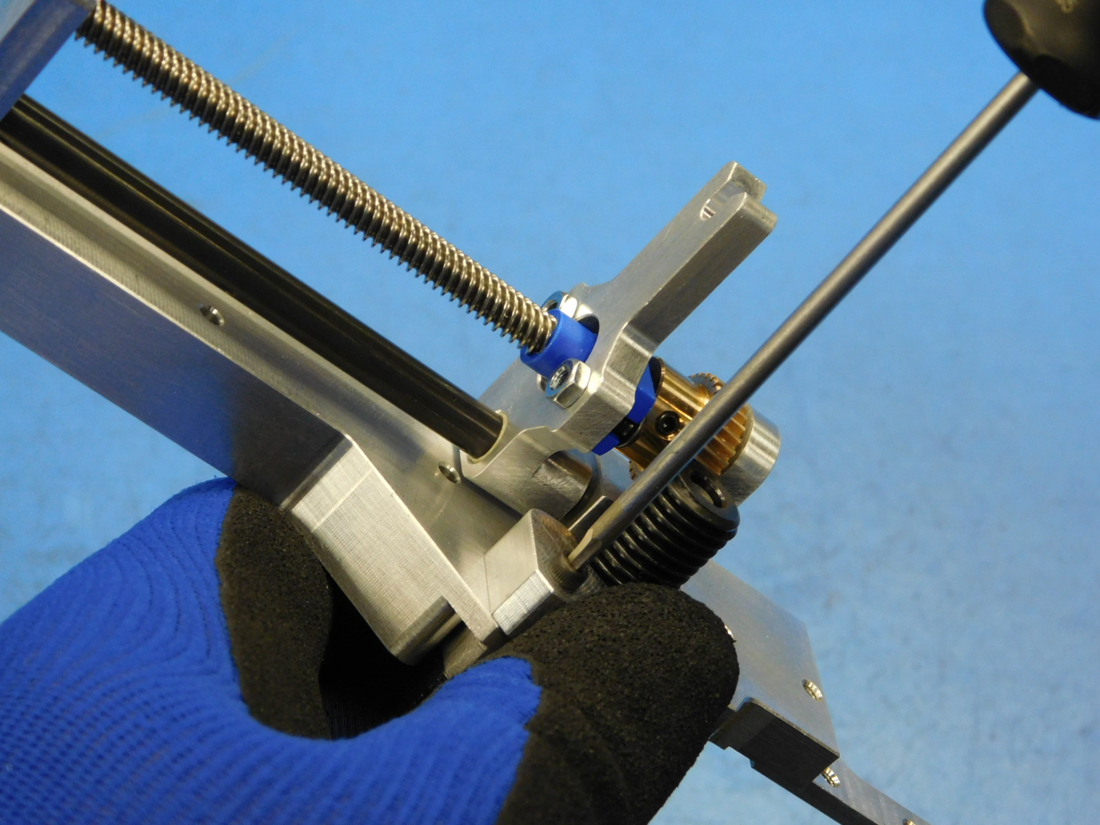
Slide the Bronze Worm Wheel [PP-MP0253] to the unthreaded portion of the Leadscrew [HD-RD0076] with the geared side towards the end of the Leadscrew.
Ensure the Worm Wheel is on the Leadscrew as fas as it will go; the top of the Worm Wheel should mate against the start of the Leadscrew threads. See photo
b.)
Torque the set screw of the Worm Wheel to the flat side of the Leadscrew to 2 in*lbs.
a)
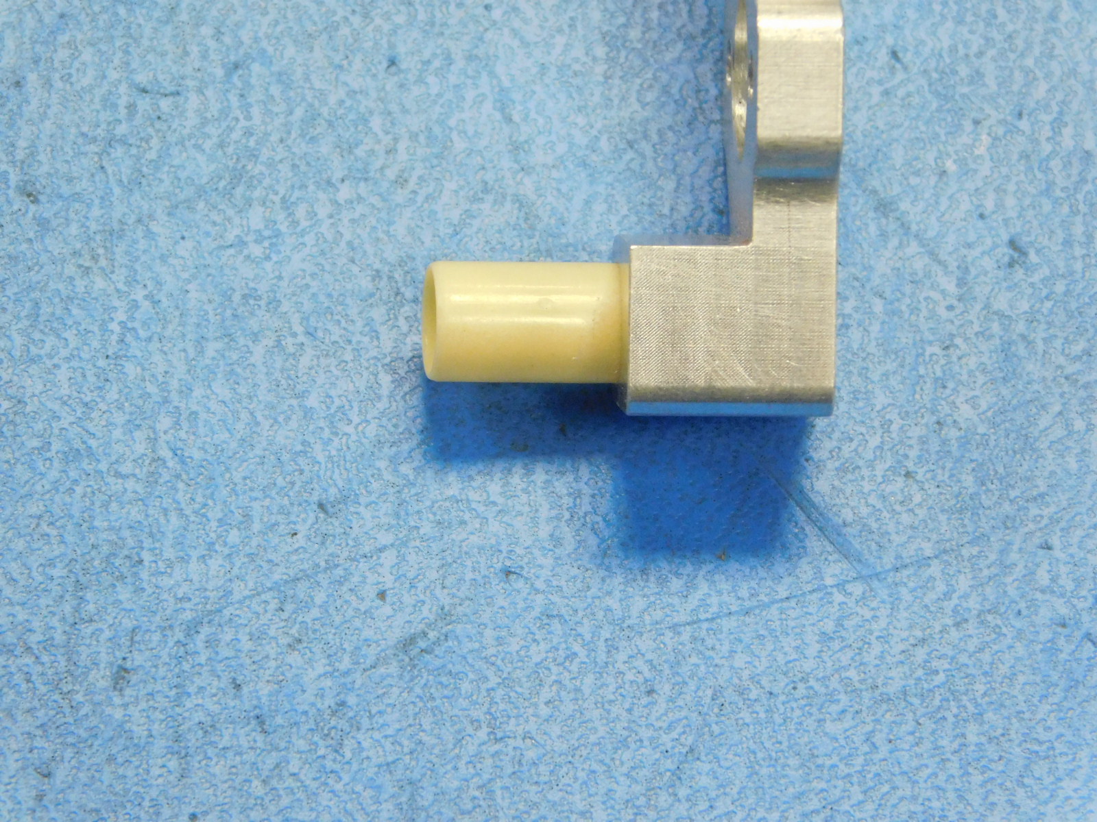
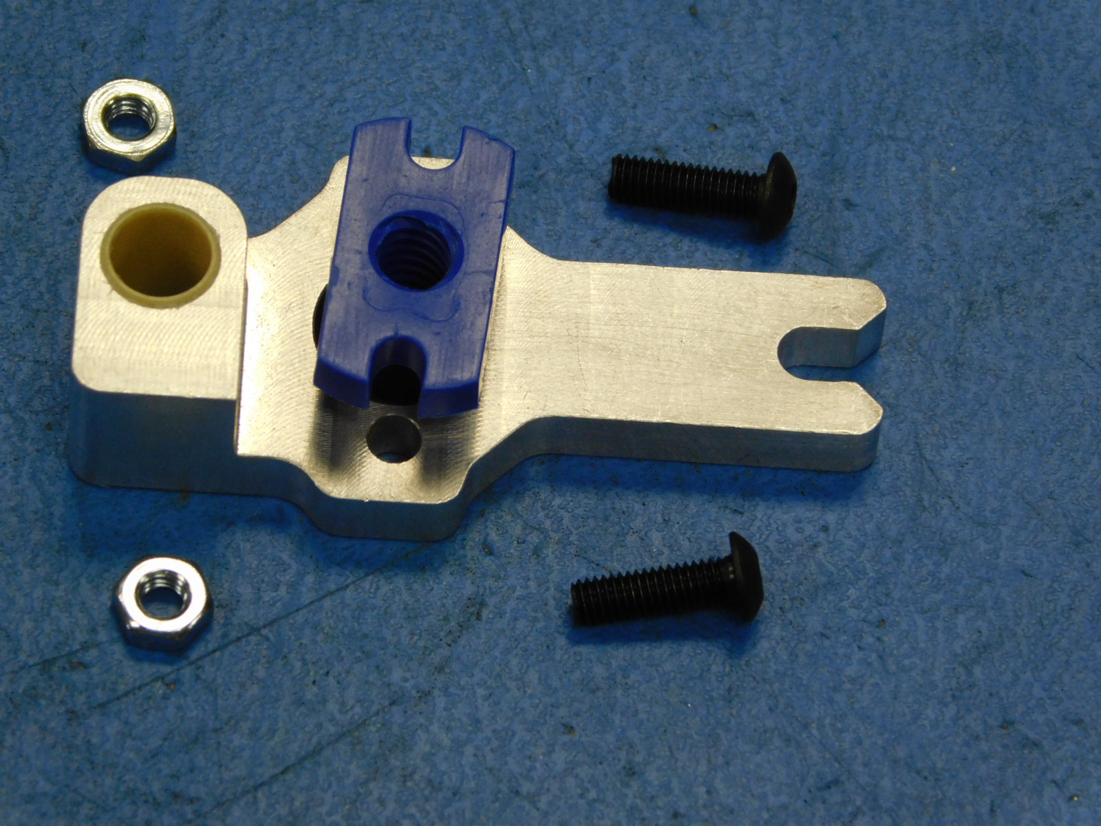
Start one Sleeve Bearing [HD-BU0051] in the hole of the Carriage [PP-MP0281] in the orientation shown.
b)
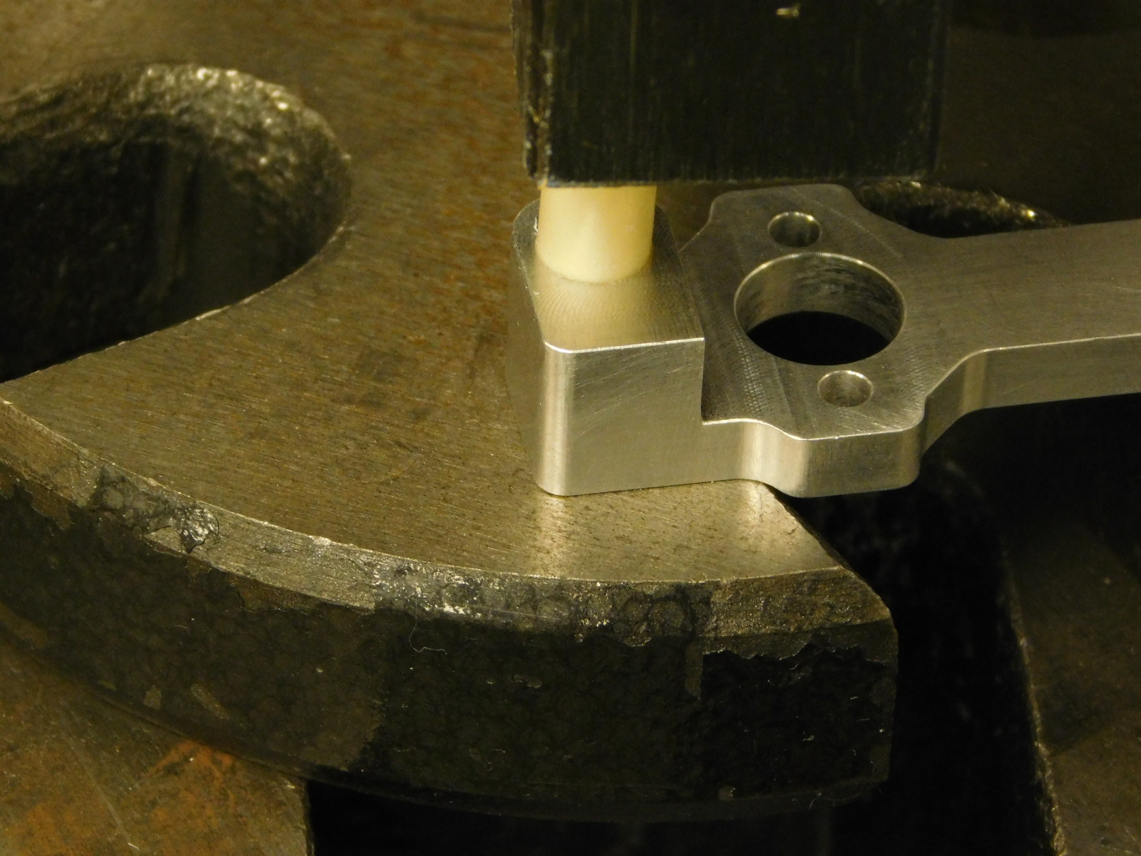
Place the Carriage [PP-MP0281] flat side down on a flat portion of the arbor press working area.
c)
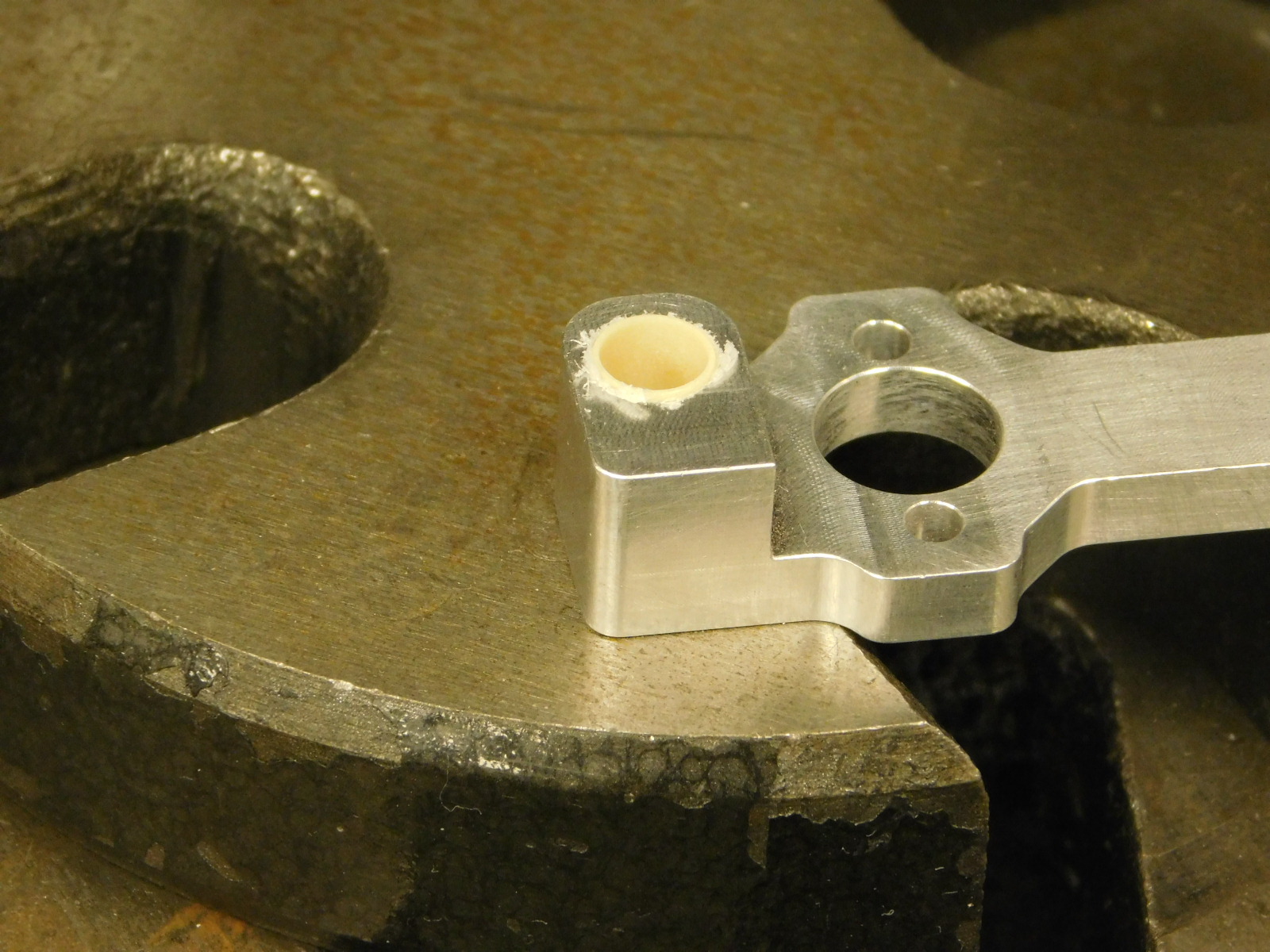
Use the arbor press to slowly push the Sleeve Bearing into the Carriage until it bottoms on the arbor press plate. Do not compress the sleeve bearing further as it will mushroom the end and could cause additional drag.
d)
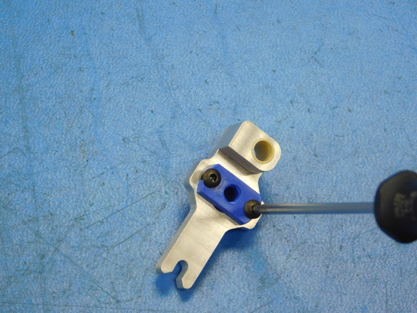
Using two M3x8 BHCS [HD-BT0137], secure the Helix - Lead Nut [HD-NT0359] to the Carriage as shown.
Early builds use M3x10 BHCS HD-BT0148 with M3 Nuts HD-NT0004, production parts should have these holes threaded
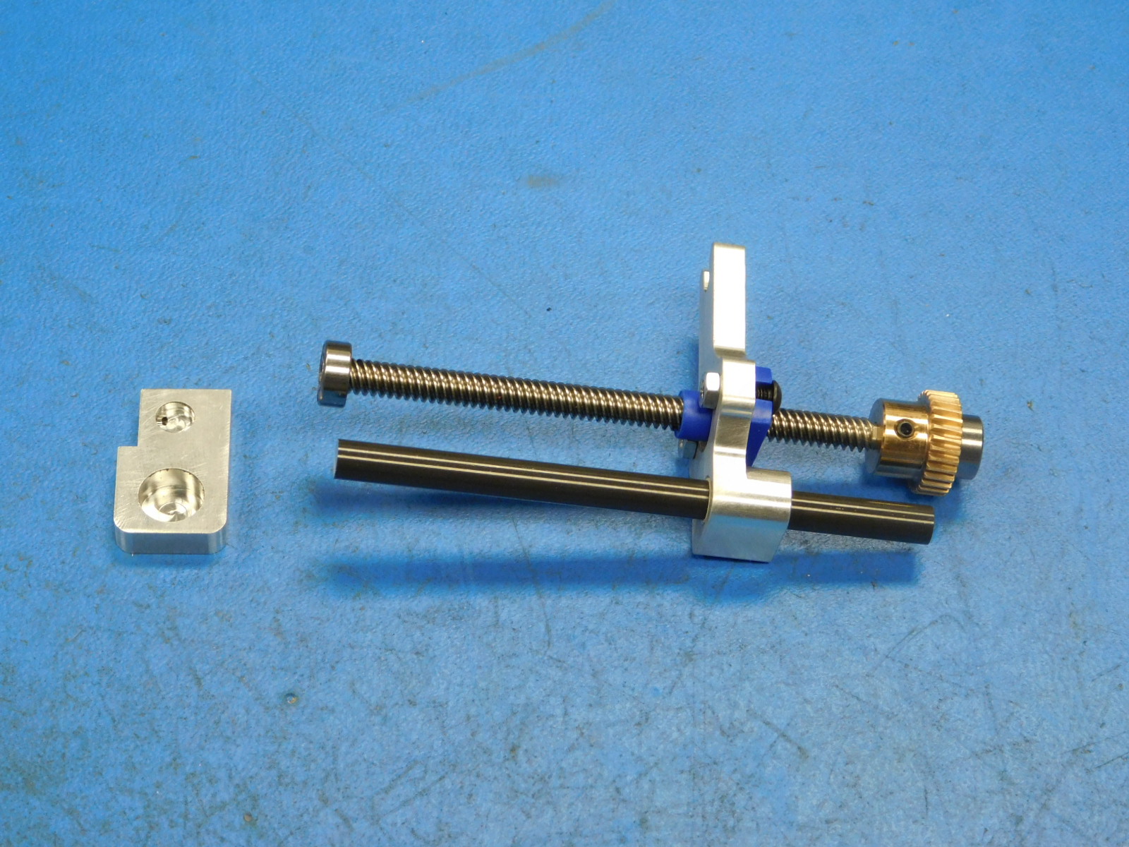
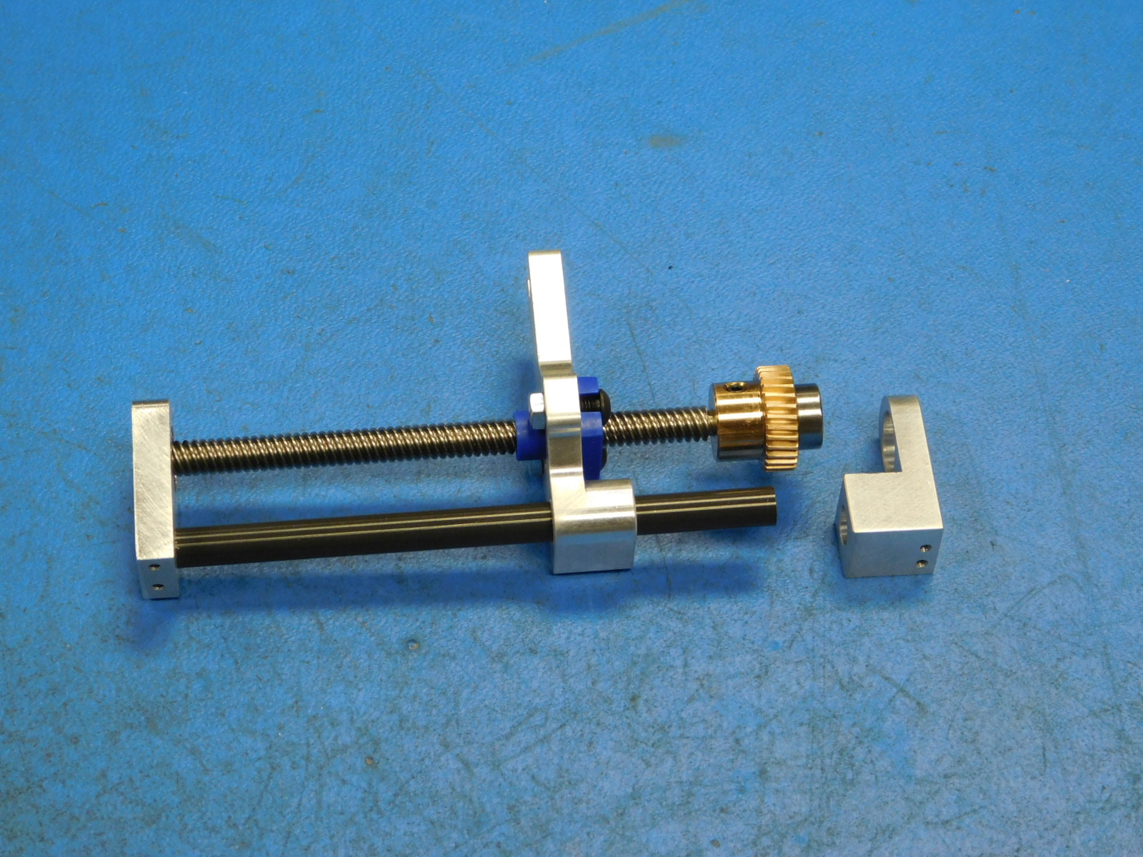
a)
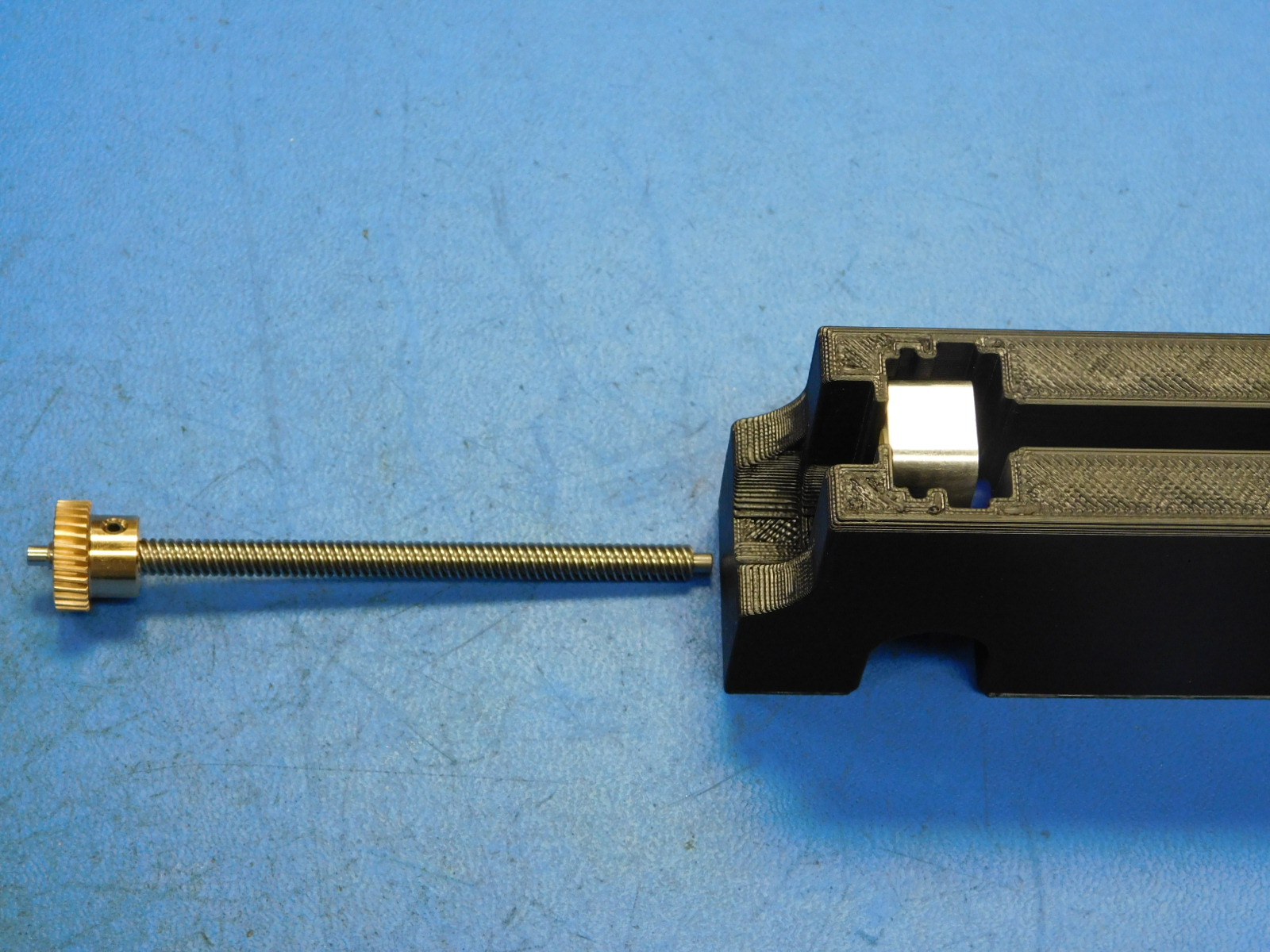
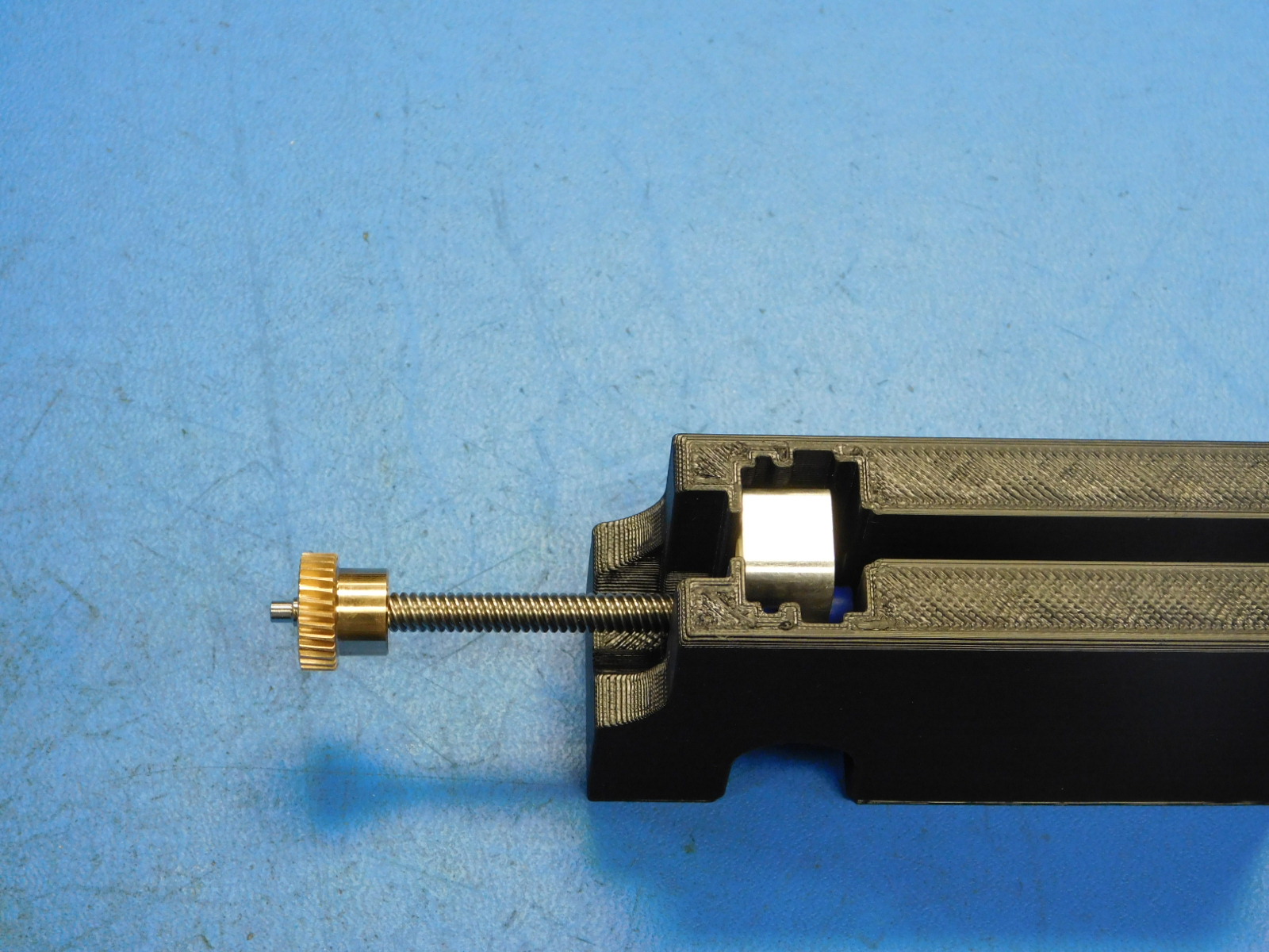
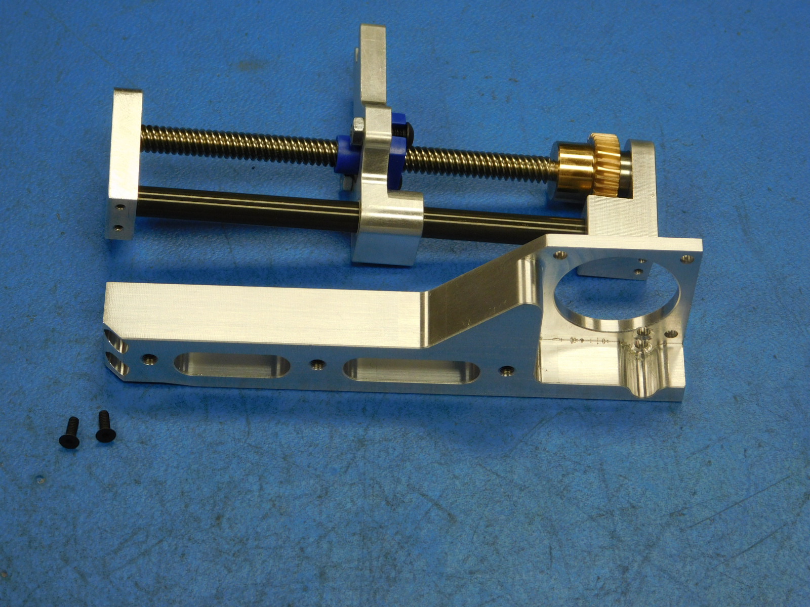
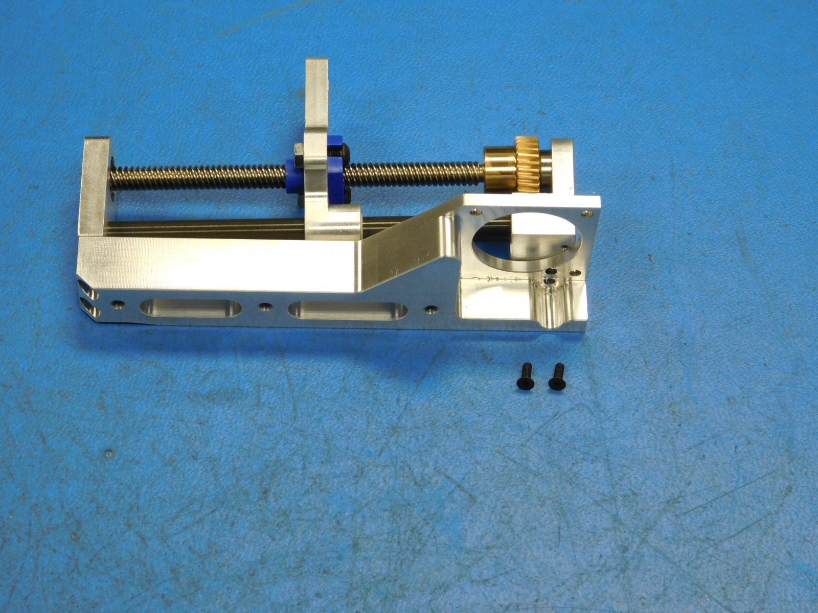
Place the assembled carriage into the assembly jig as shown (only fits in one orientation).
b)
Thread the end of the Leadscrew opposite the Worm Wheel into the Lead Nut of the Carriage until the Worm Wheel bottoms out in the jig.
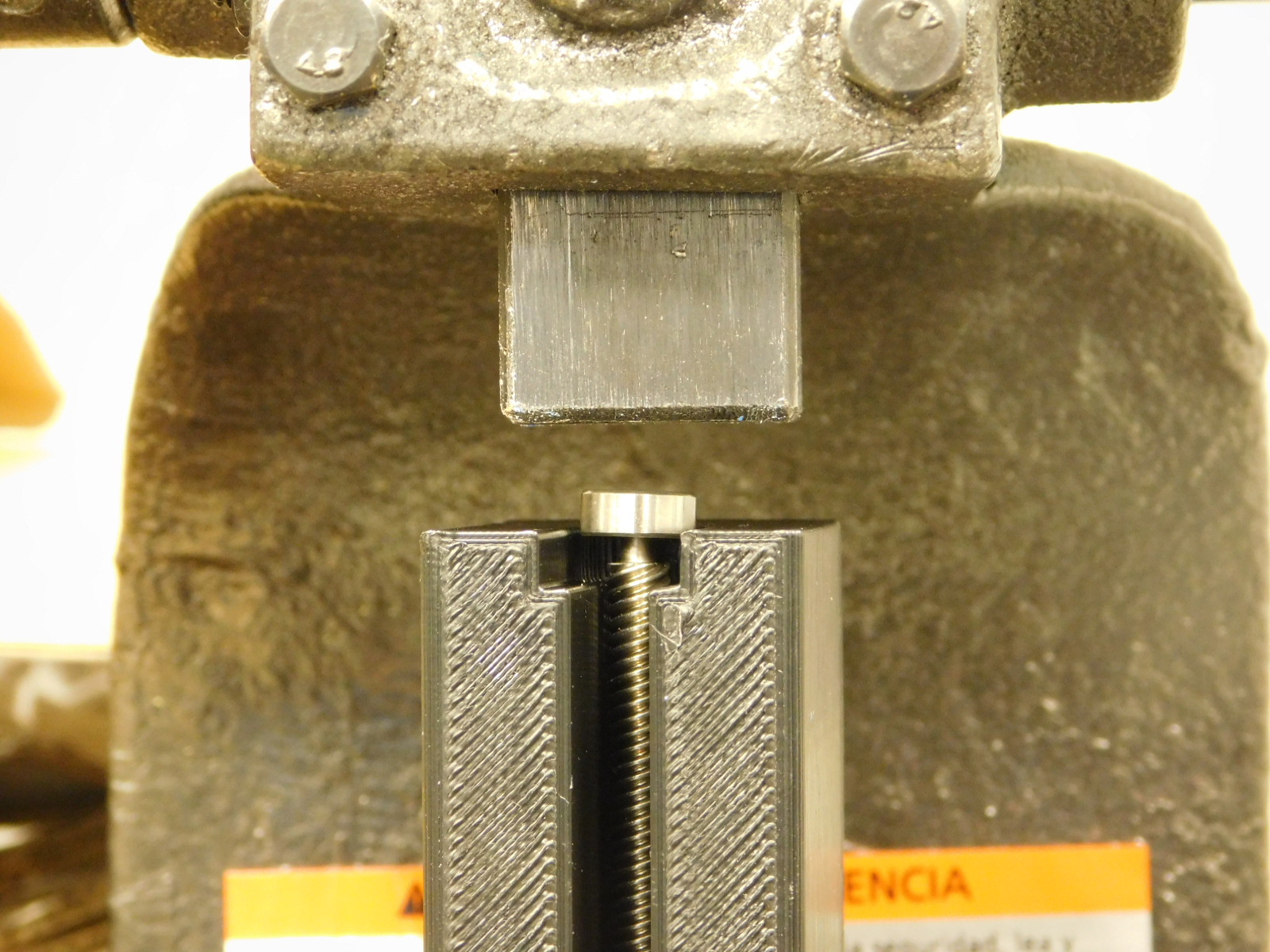
a)
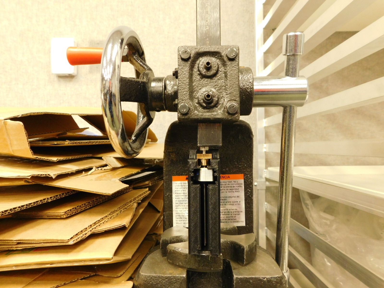
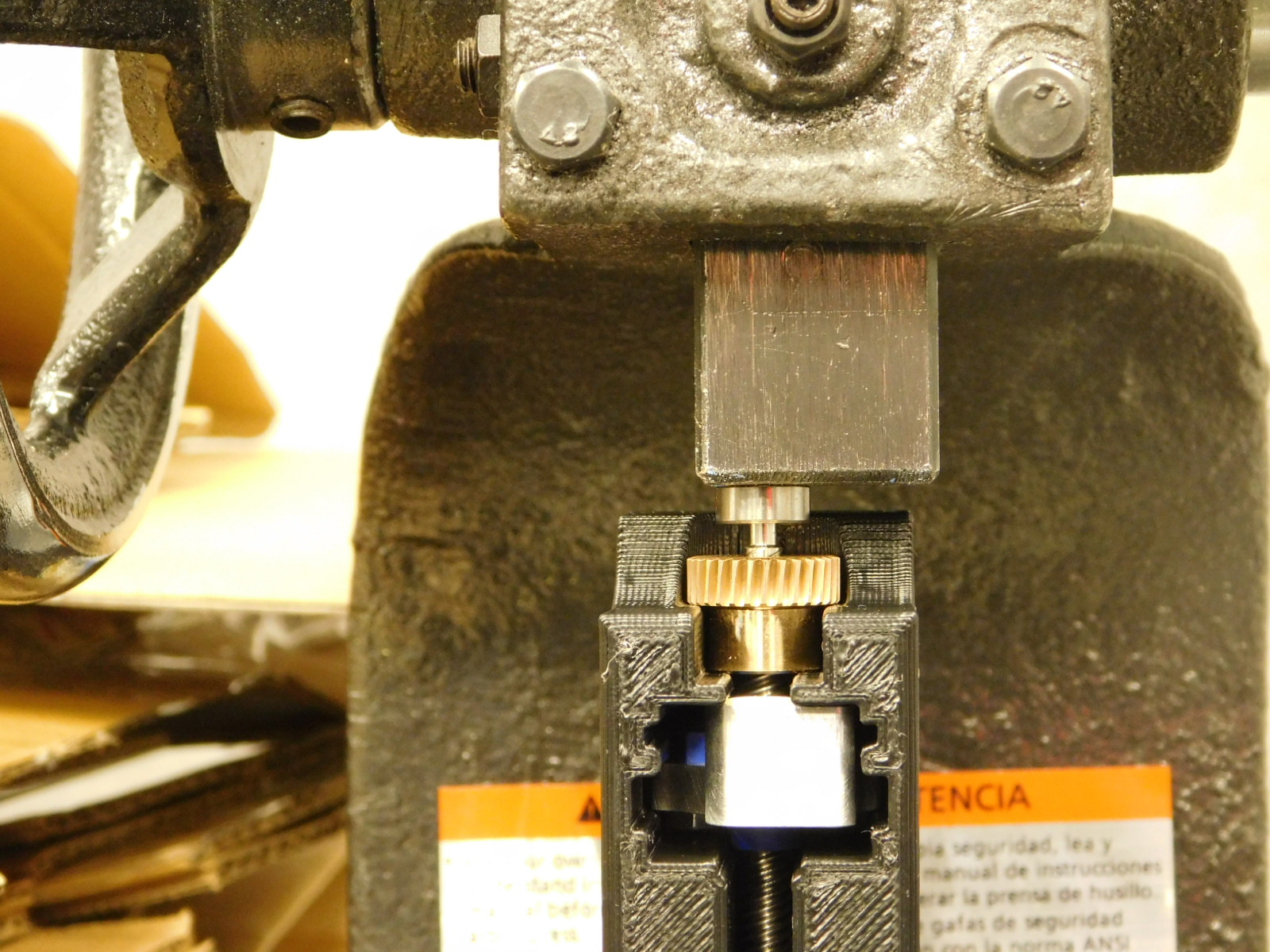
At the arbor press, place the part/jig from the previous step into the working area of the arbor press with the bronze Worm Wheel facing up.
Ensure the Worm Wheel end is tightened into the jig by spinning it, before pressing bearings into place.
b)
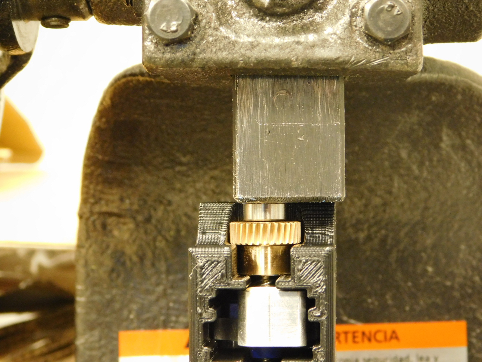
Place one bearing [HD-MS0470] on the end of the Leadscrew and use the arbor press to press it into place.
Visually inspect to ensure the bearing is fully seated on the end of the Leadscrew.
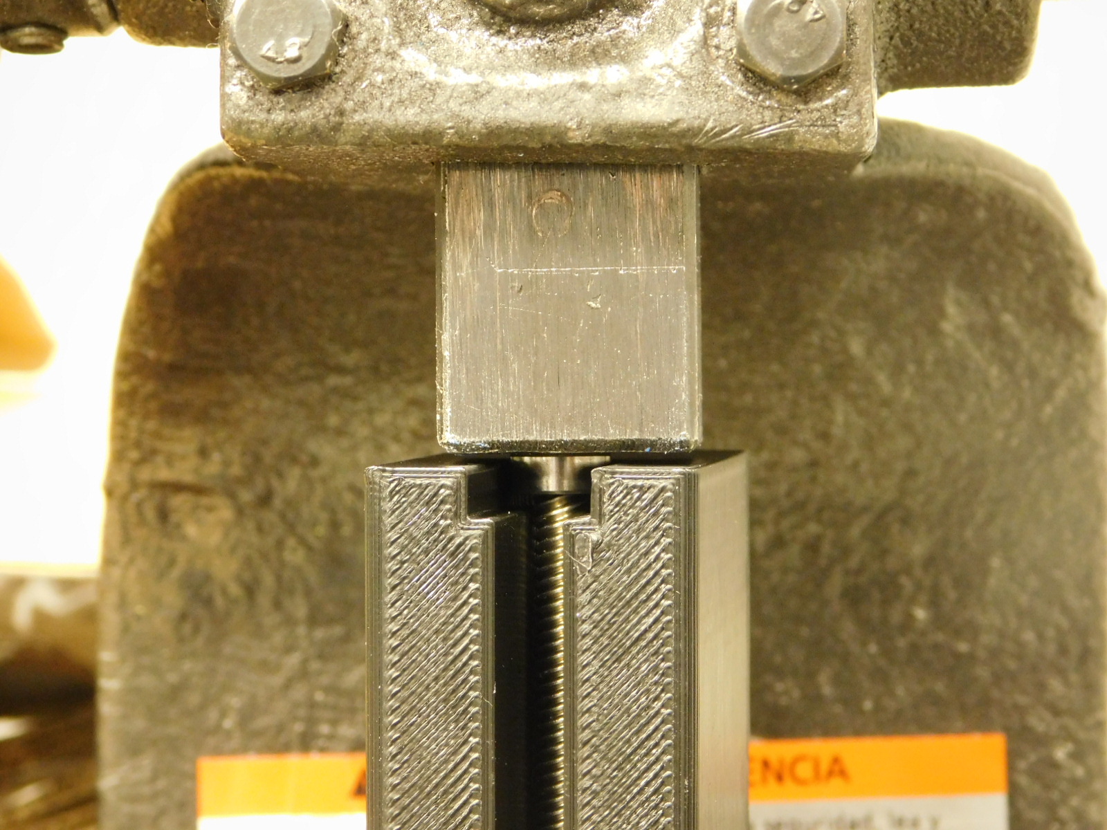
c)
Rotate the jig in the arbor press working area so that the opposite end of the Leadscrew faces up.
d)
Place one bearing [HD-MS0470] on the end of the Leadscrew and use the arbor press to press it into place.
Visually inspect to ensure the bearing is fully seated on the end of the Leadscrew.
e)
Use the finger notch on the rear/bottom of the jig to eject the completed Leadscrew assembly.
a)
Obtain one Upper Bearing Holder [PP-MP0277] and press it onto the bearing at the opposite end of the bronze Worm Wheel.
b)
Slide one Smooth Rod [HD-RD0077] through the sleeve bearing of the Carriage and into the hole in the Upper Bearing Holder.
c)
Obtain one Lower Bearing Holder [PP-MP0278] and press it onto the bearing at the Leadscrew end with the bronze Worm Wheel. Ensure the end of the smooth rod enters the hole in the lower bearing holder.
a)
Obtain one Motor Mount [PP-MP0279]
b)
Using two M2x6 FHCS [HD-BT0244], attach the Upper Bearing Holder to the Motor Mount.
Before tightening, ensure the edges of the Upper Bearing Holder and Motor Mount mate flush and square.
c)
Using two more M2x6 FHCS [HD-BT0244], attach the Lower Bearing Holder to the Motor Mount.
d)
Torque all four fasteners to 2in\lbs
a) Obtain one Steel Worm Gear [PP-MP0252] and one NEMA 11 Motor [EL-MT0063]
b)
Using the pulley spacer jig, attach the Steel Worm Gear to the shaft of the NEMA 11 Motor with the set screw towards the motor.
c)
Torque the set screw against the flat side of the motor shaft to 2in*lbs
d)
Place the Motor (w/ Worm Gear) on top of a paper towel.
Give a quick shot of White Lithium spray to one side of the Worm Gear and then rotate and apply another quick shot to the other side of the Worm Gear.
a)
Obtain one Collar Mount Flange [PP-MP0280] and 3 M2.5x14 SHCS [HD-BT0255]
b)
Orient the parts as shown
The motor's connector is facing down in the photo
c)
Thread the M2x5x14 SHCS through the Collar Mount Flange and the Motor Mount, and into the threaded holes on the motor.
d)
Apply pressure to the motor so that the Steel Worm Gear is pressed as close to the bronze Worm Wheel as possible and tighten the fasteners.
e)
Torque all 3 fasteners to 3in*lbs

a)
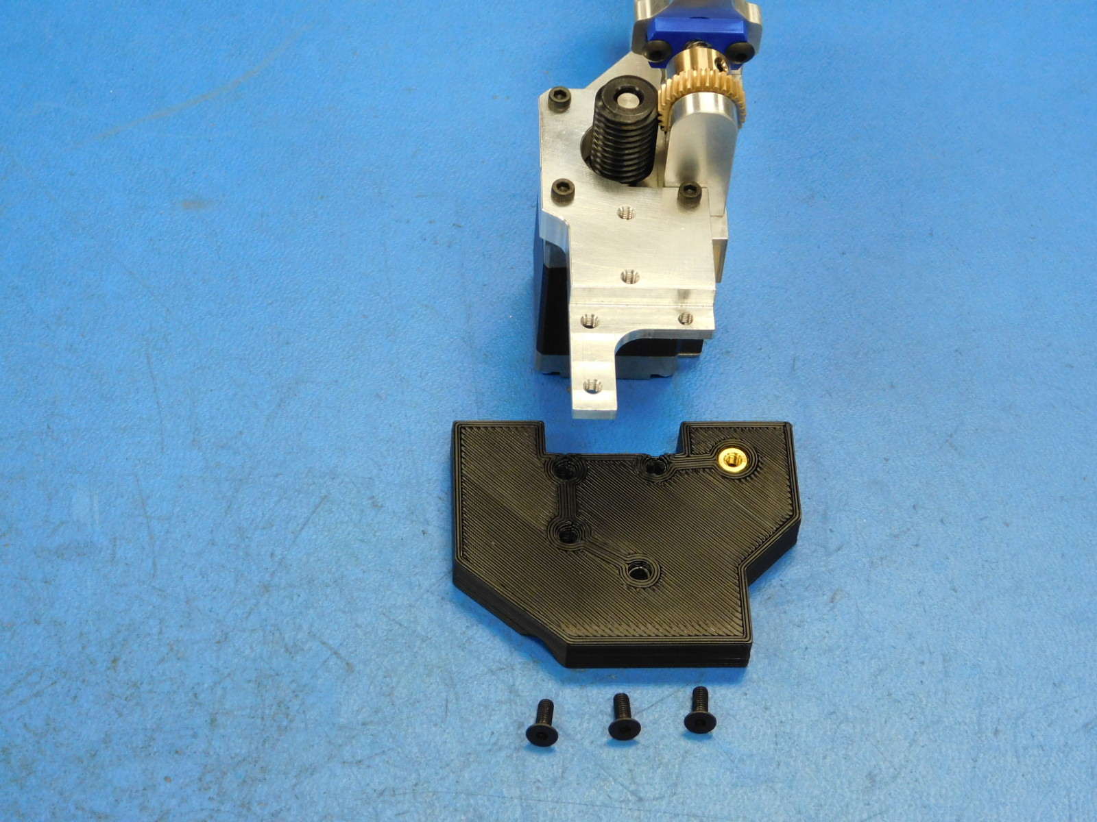
Obtain one Syringe Pump Mount w/ Inserts [PP-IS0120] and 3 M3x8 FHCS [HD-BT0119]
b)
Place the Syringe Pump Mount w/ Inserts onto the bottom of the Collar Mount Flange as pictured.
c)
Secure using the 3 M3x8 FHCS, torqued to 5in*lbs
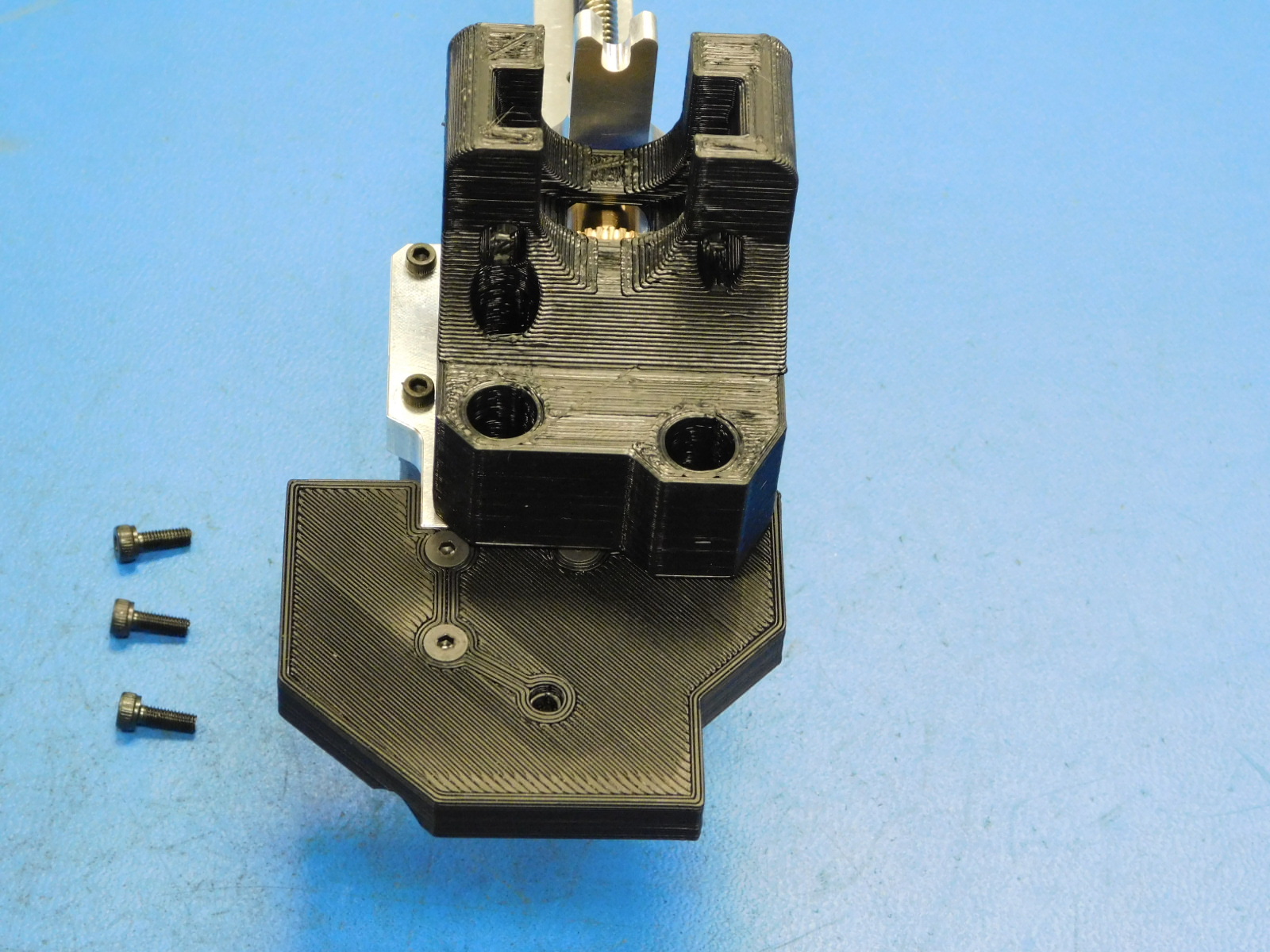
a)
Obtain one Syringe Collar Mount and 3 M3x10 SHCS [HD-BT0005]
b)
Place the Syringe Collar Mount on the Collar Mount Flange as pictured.
c)
Secure using the 3 M3x10 SHCS, torqued to 5in*lbs
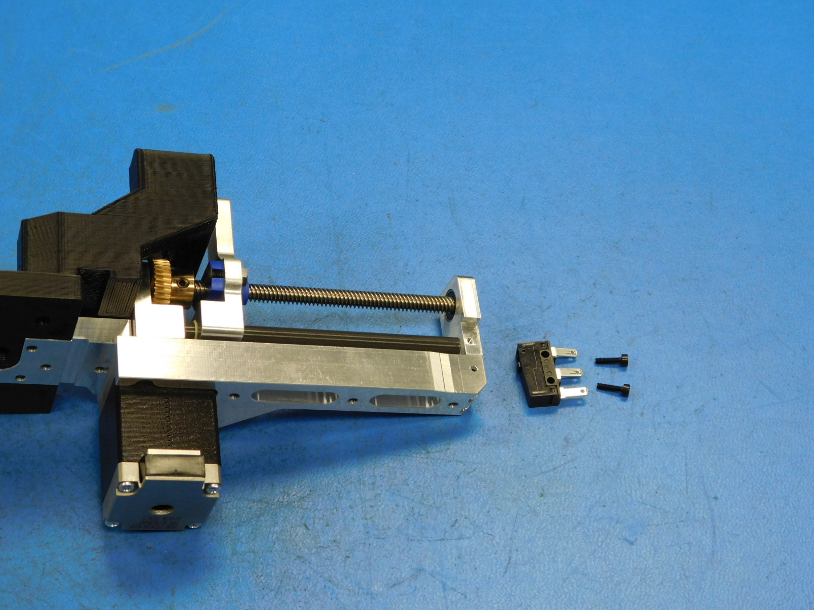
a)
Obtain one Endstop Switch [EL-SW0022], two M2x8 [HD-BT0259], and 1 Syringe Pump Harness [EL-HR0190]
b)
Attach the Endstop Switch [EL-SW0022] to the assembly with the tab facing down and forward, using two M2x8 [HD-BT0259]
Torque to 2in*lbs
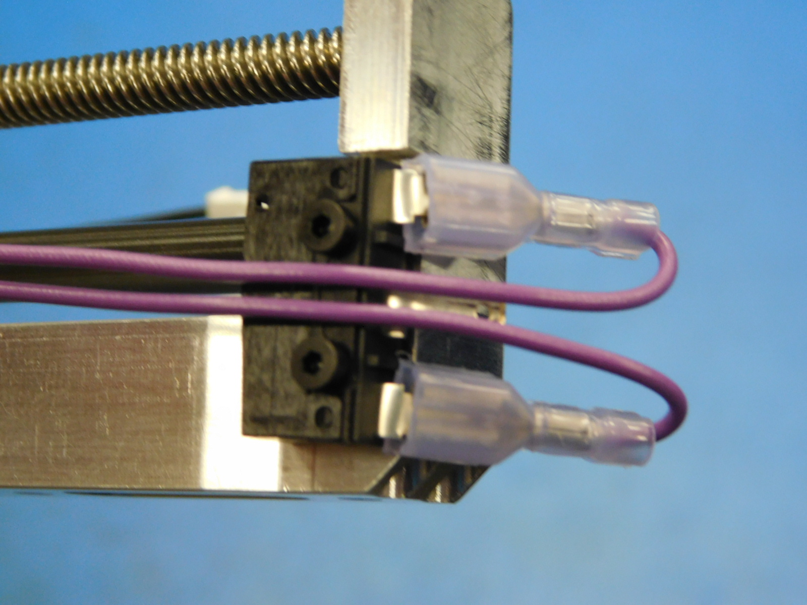
c)
Attach the Syringe Pump Harness [EL-HR0190] to the Endstop Switch outer tabs.
Bend the Endstop Switch tabs in towards the Motor Mount.

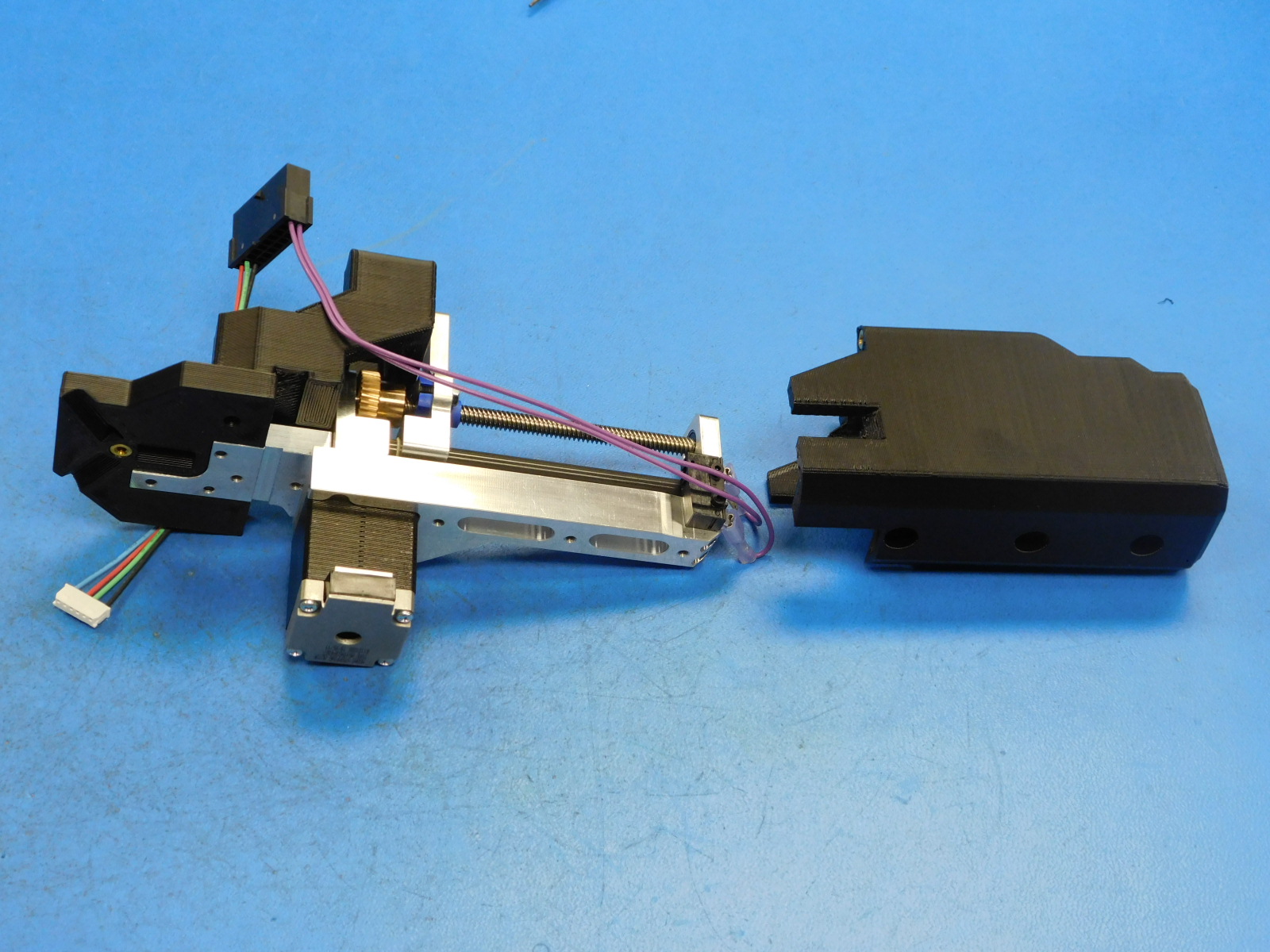
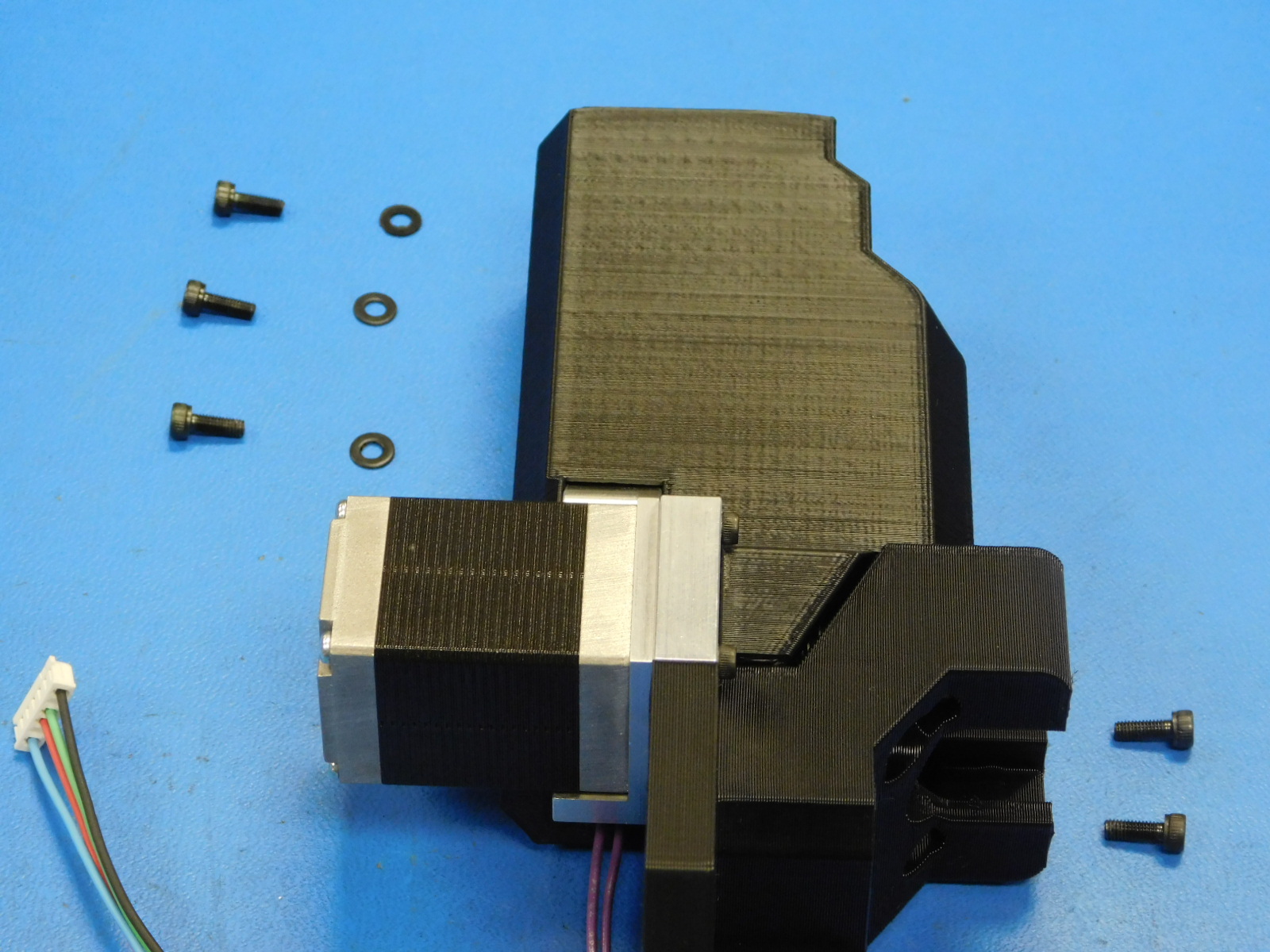
a)
Obtain one Syringe Pump Cover w/ Inserts [PP-IS0121], five M3x8 SHCS [HD-BT0157], and three M3 Black Washers [HD-WA0038]
b)
Route the Endstop Switch leads (purple wires) down between the two outer tabs of the switch and down the side of the motor mount, as shown in the photos.
c)
Slide the Syringe Pump Cover onto the assembly
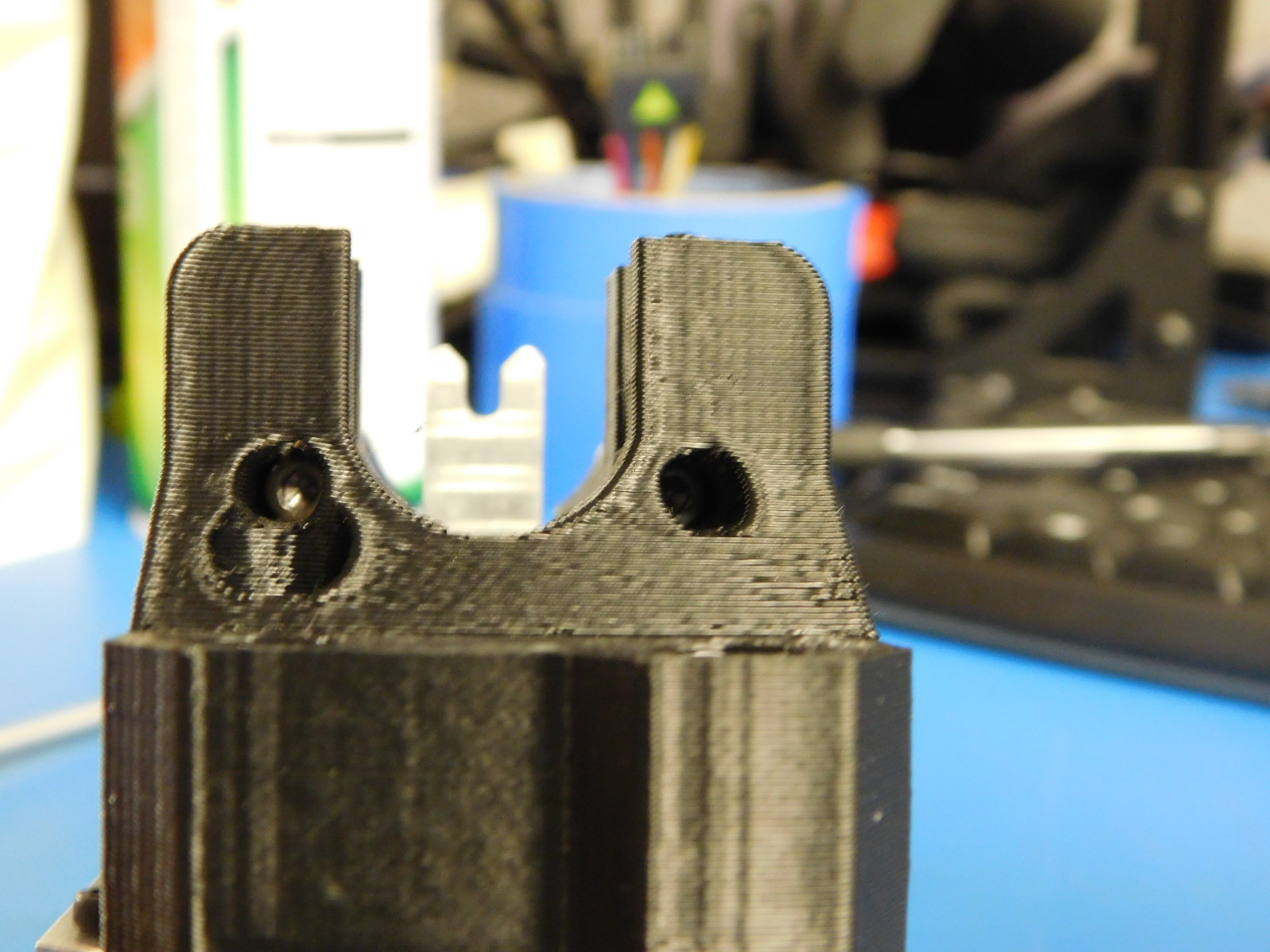
d)
Secure the cover from below the collar mount using 2 M3x8 SHCS
Secure from the rear using 3 M3x8 SHCS with washers
Torque all 5 fasteners to 3in*lbs
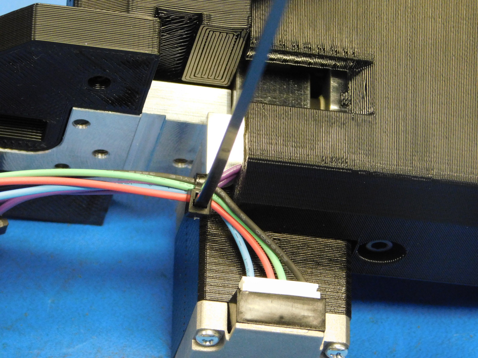
a)
Obtain one Zip-tie [HD-MS0058]
b)
Connect the small white connector of the Syringe Pump Harness to the NEMA 11 Motor.
c)
Pulling the slack from the purple wires, apply one zip-tie around the motor leads and the endstop leads, as close to the corner of the Syringe Pump Cover, as shown.
d)
Cut excess zip-tie flush with the latch.
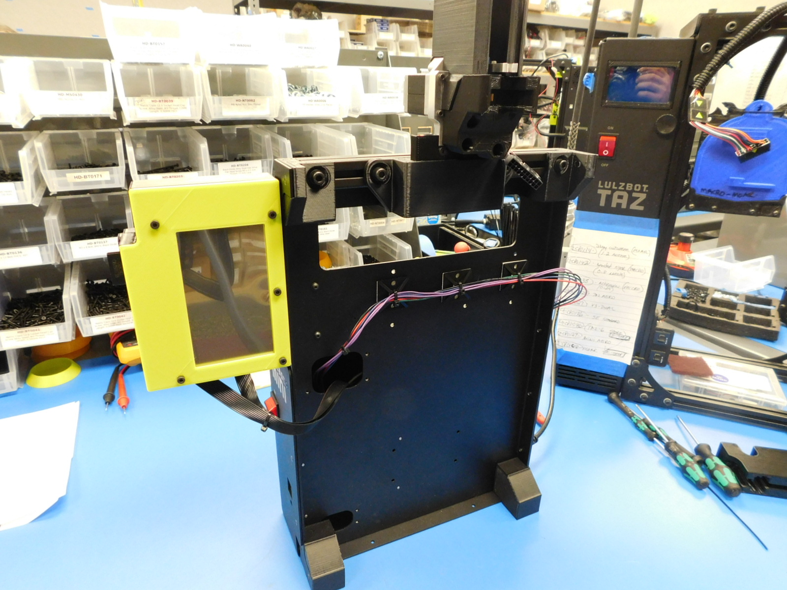
Attach the completed Syringe Pump Assembly [AS-TH0077] to the test stand by sliding the mount into the hanger.
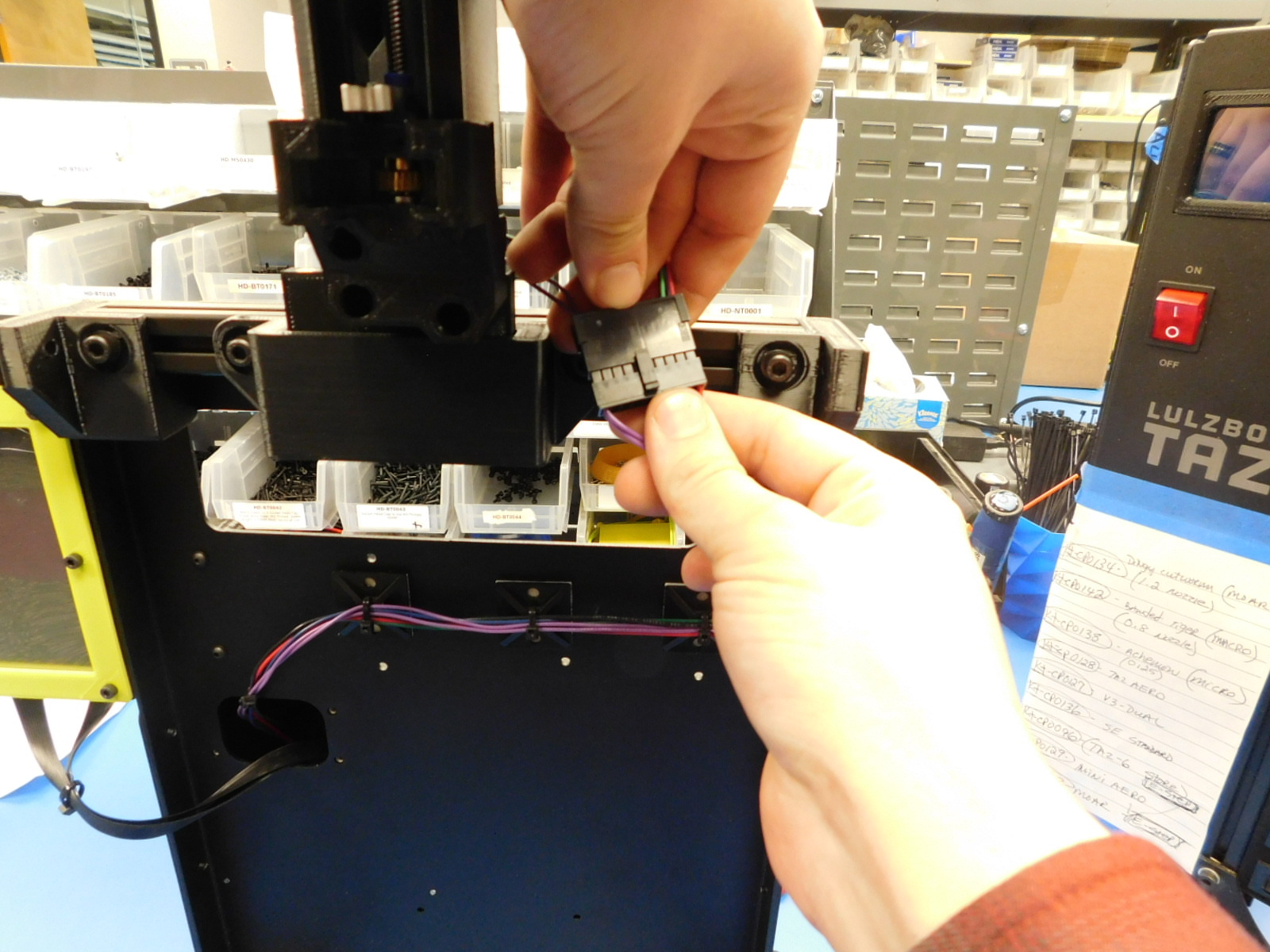
Connect the extruder harness of the test stand to the Syringe Pump Harness of the completed assembly.
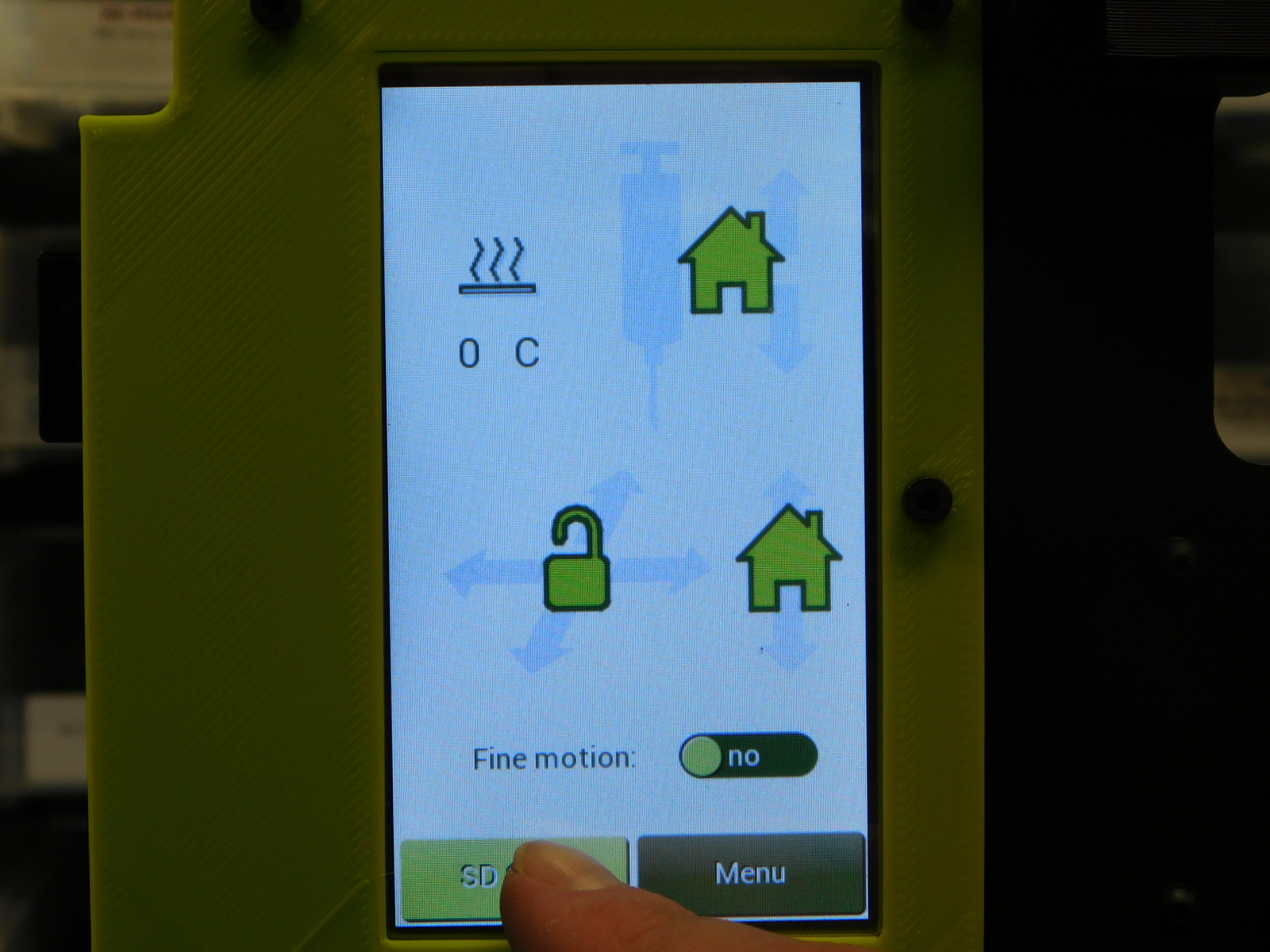
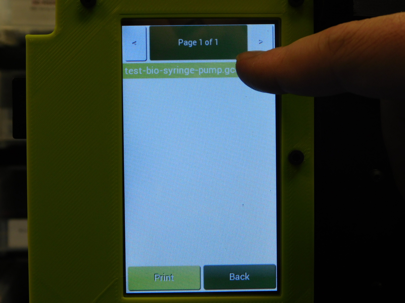
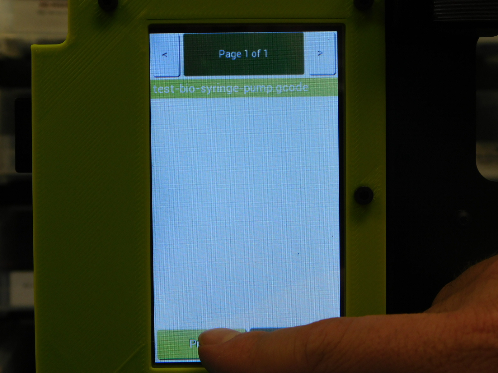
Power on the test stand and wait for it to boot
Once booted, select NO at the first prompt
Select Media and run "test-bio-syringe-pump.gcode"
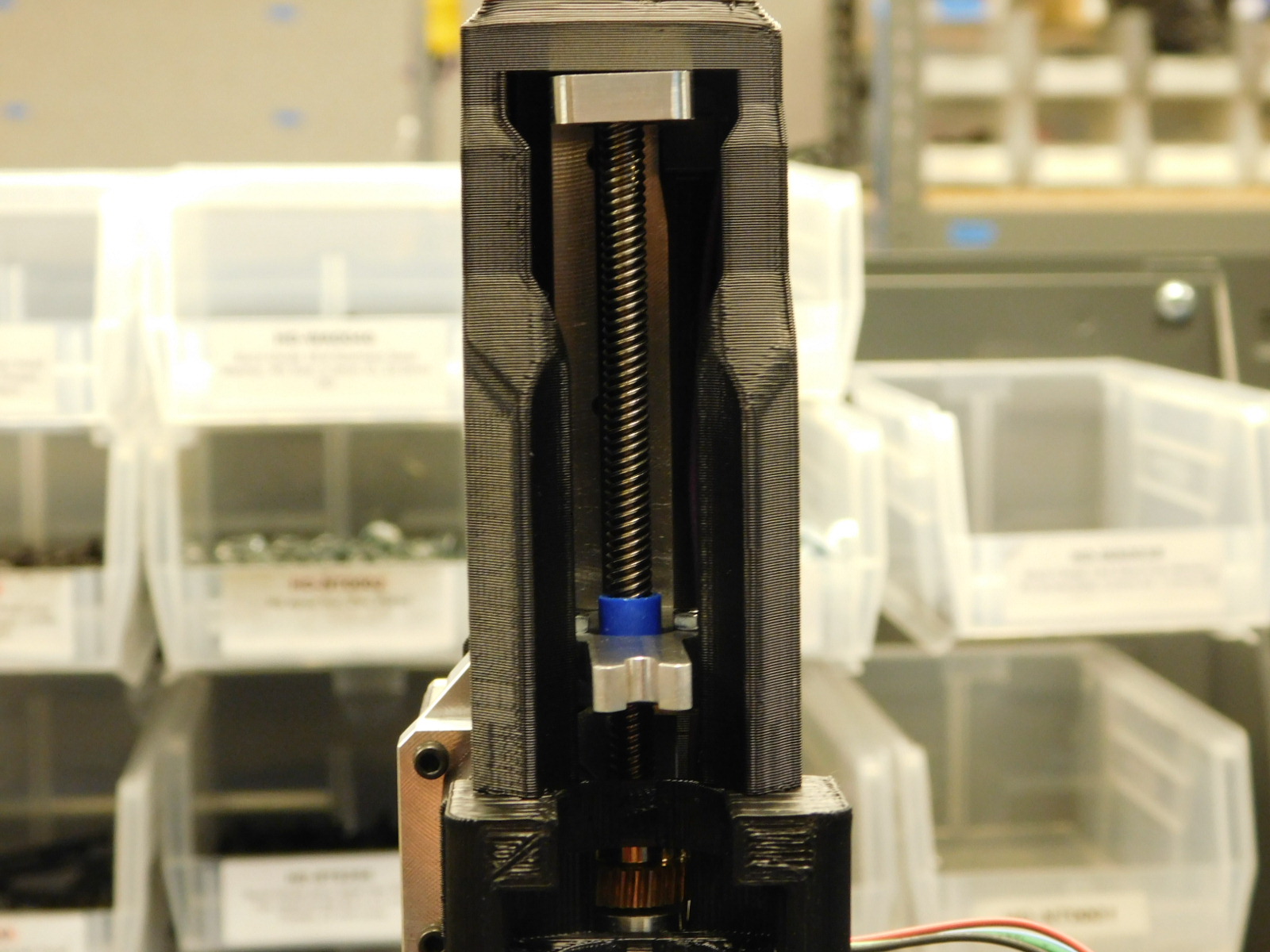
The carriage of the syringe pump will move upwards to the limit switch, back down to the lower travel limit, and then re-home.
Observe the test to ensure both the upper and lower travel limits are reached without binding.
When a Syringe Pump binds, it should make a louder vibration or a sound similar to grinding.
If any high pitched squeaks are heard, ensure the worm gear and worm wheel are sufficiently lubricated.
Some disassembly may be required to apply additional lubricant.