Open HardwareAssembly Instructions
Guides for installation and assembly of the LulzBot line of products made by Aleph Objects, Inc.
Guides for installation and assembly of the LulzBot line of products made by Aleph Objects, Inc.
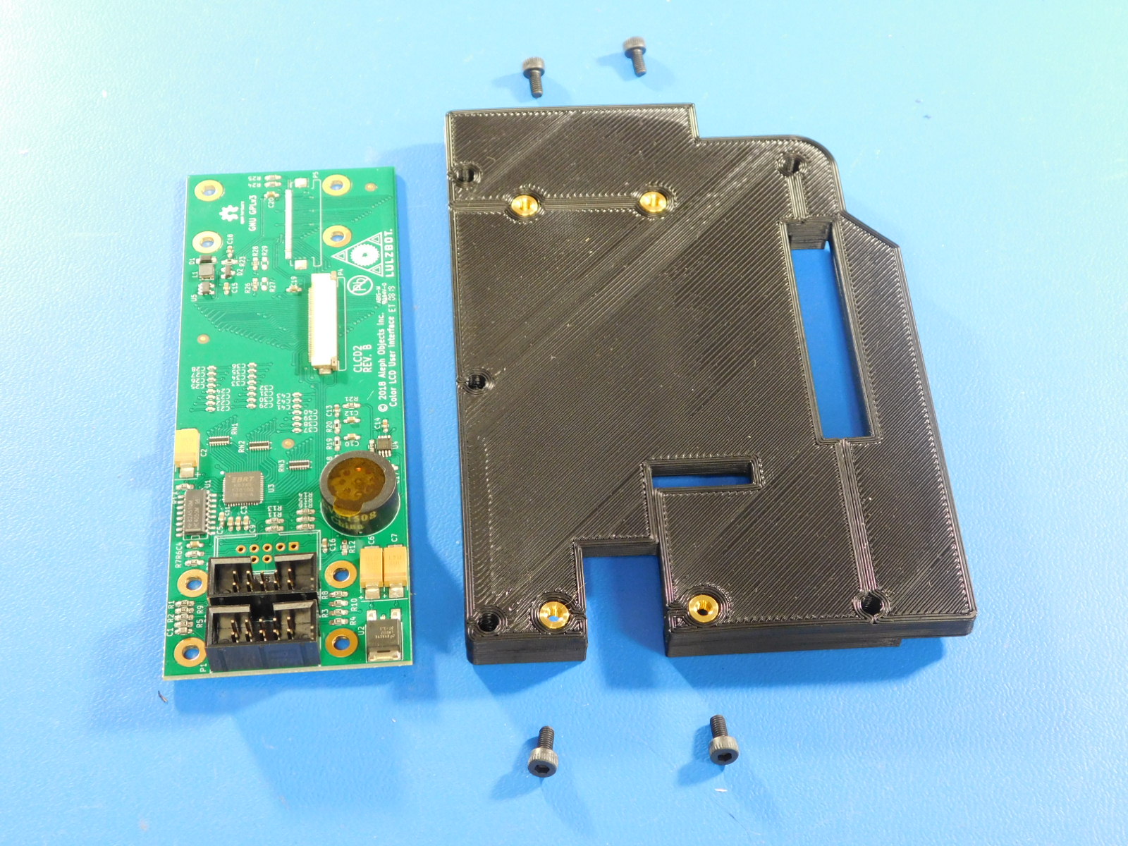
a) Obtain one [PP-IS0123] LCD center, with inserts, a [PC-BD0117] Color_LCD_ Board CLCD2 Rev B, and 4x [HD-BT0260] M3 x 6mm Bolt, SHCS, Stainless Steel and orient as shown.
b) Pull the sticker off of the speaker of the lcd controller.
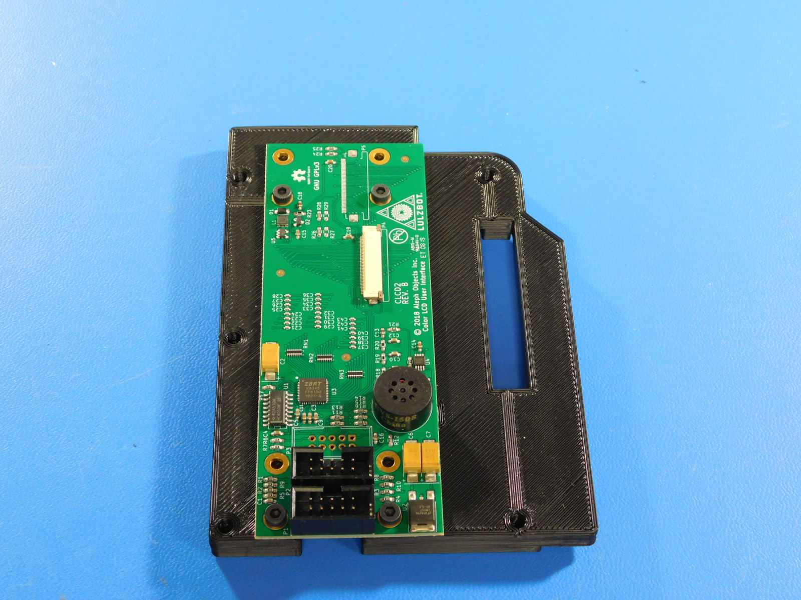
c) Secure the lcd controller to the lcd center using 4x M3x6 SHCS bolts.
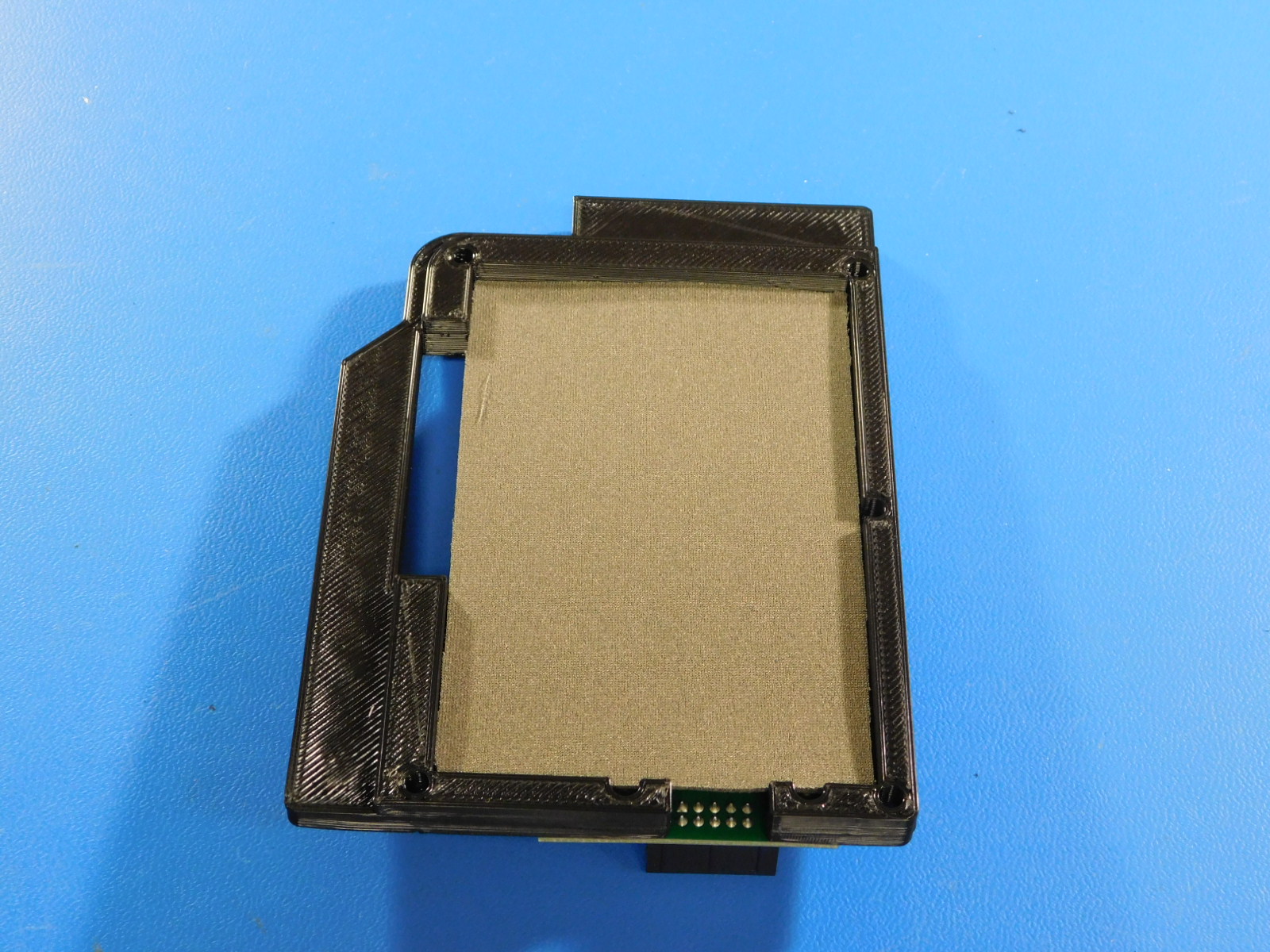
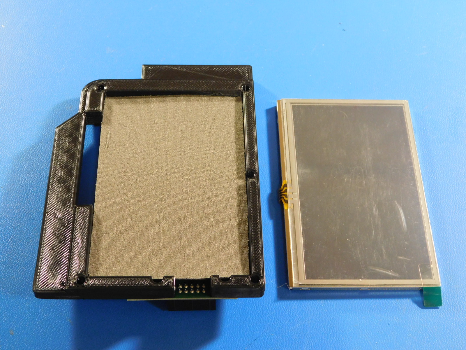
a) Obtain one [PP-FP0175] touch screen pad and place it in the fitted compartment on the other side from the lcd board controller.
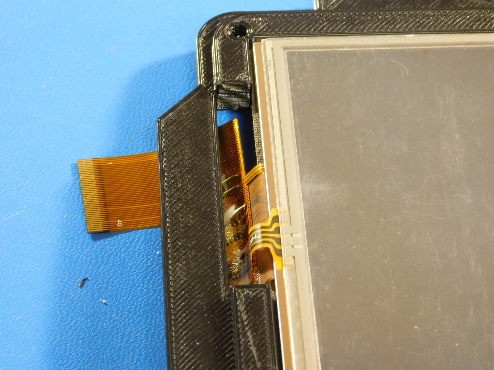
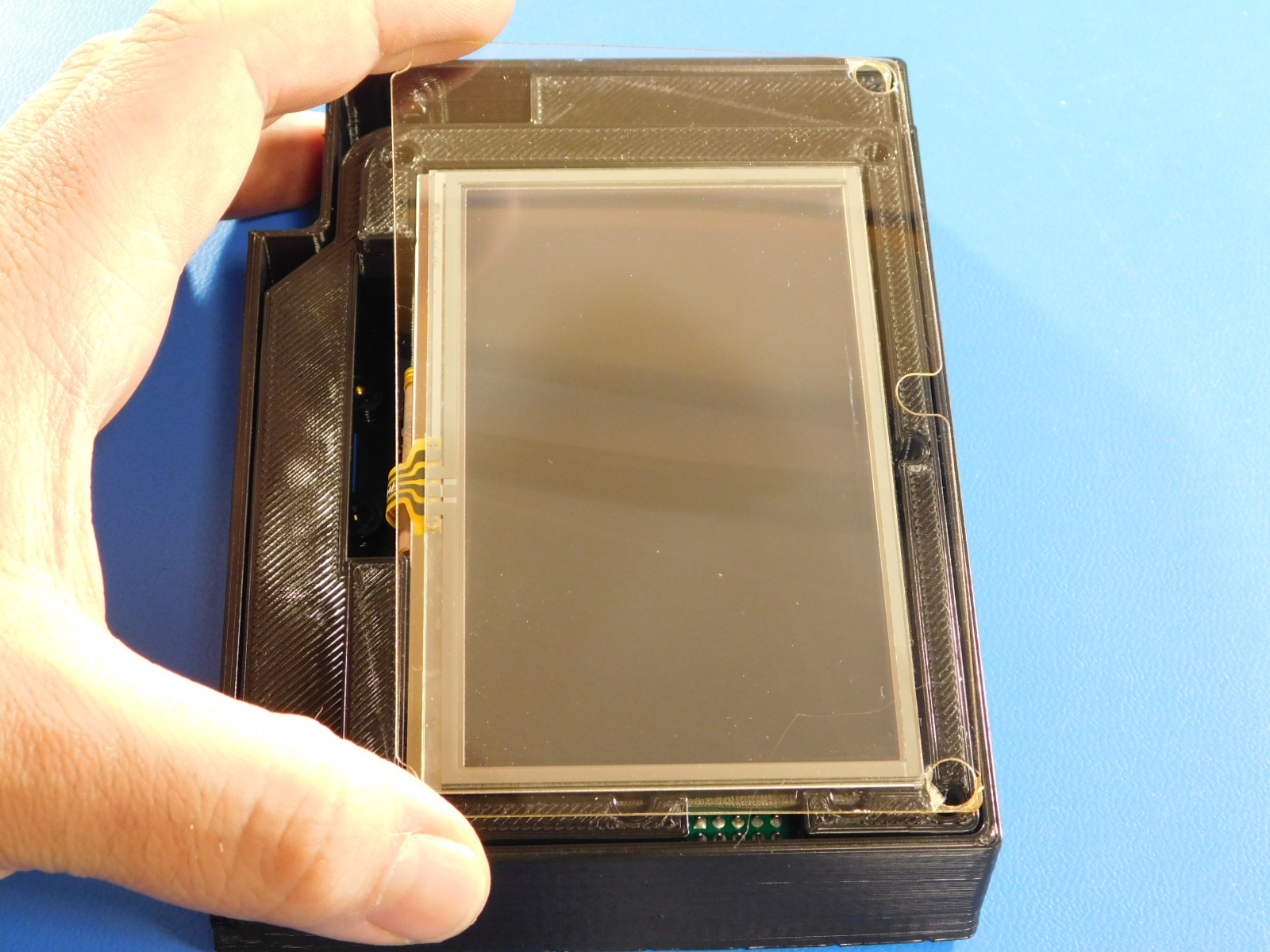
b) Obtain a [EL-MS0559] LCD touchscreen and place it in the slot on top of the touch screen pad. Route the touchscreen ribbon cable through the slot on the left side of the LCD center.
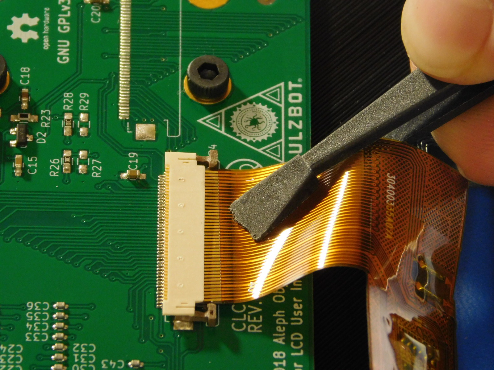
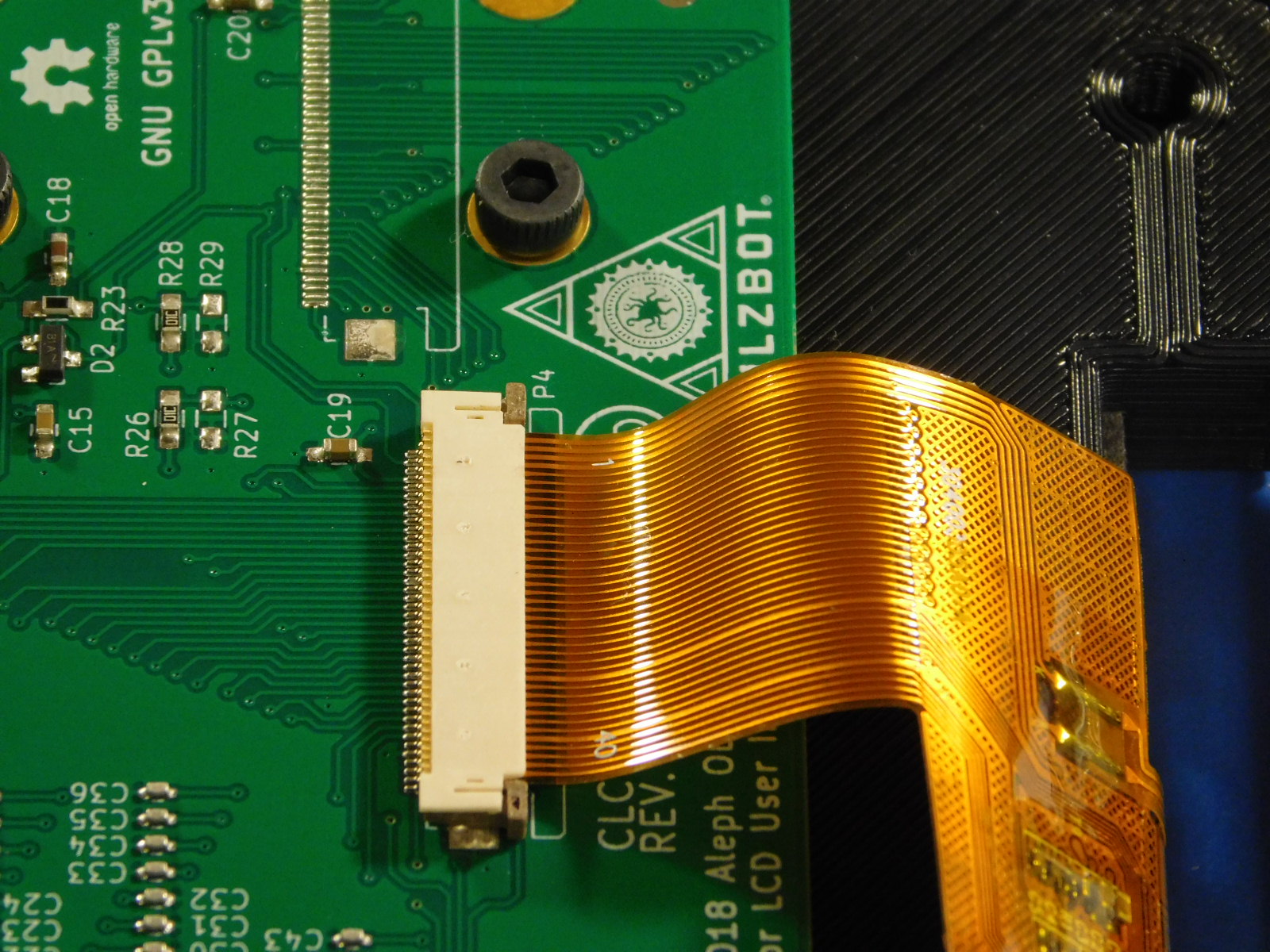
c) Make sure to un-clip the LCD cable connector and carefully slide the ribbon cable into the connector until the brass tips are fully covered. Make sure to use the designated tools.
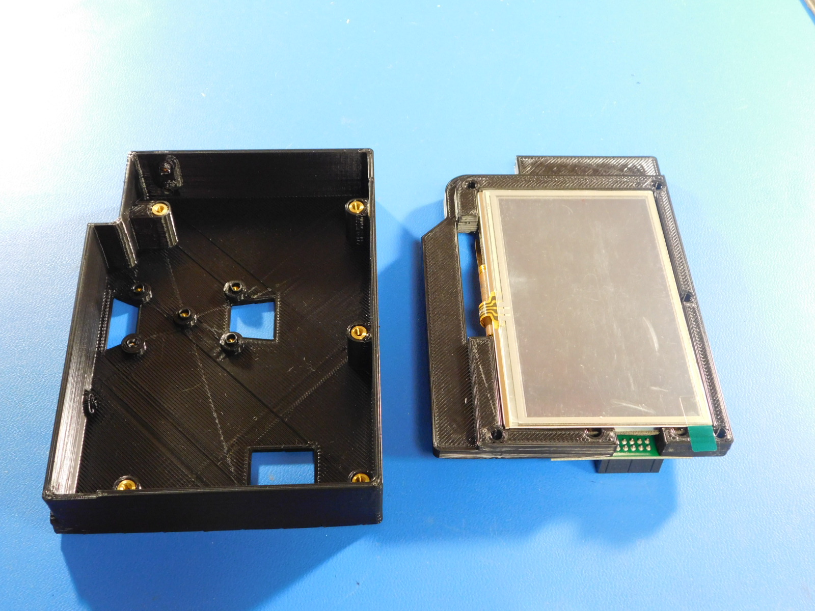
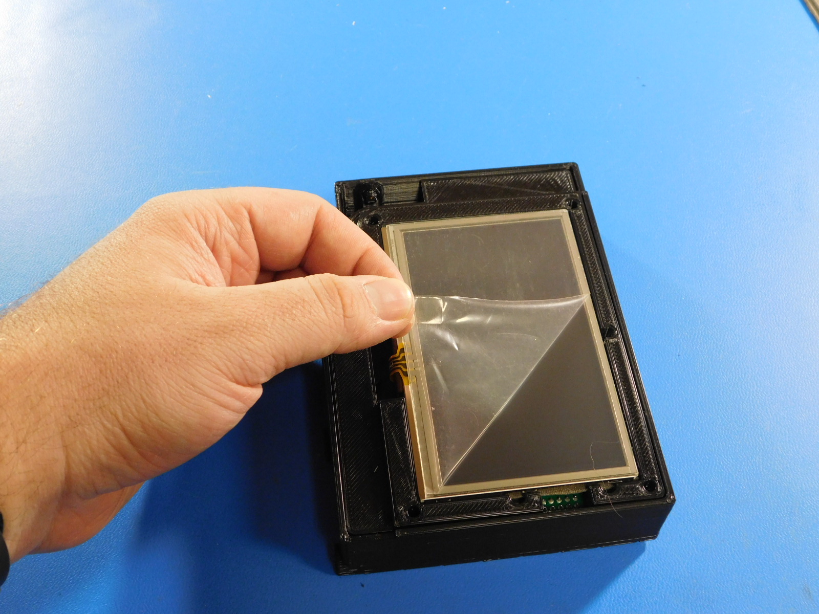
a) Place the LCD assembly in to the [PP-IS0122] LCD case with inserts so that the edges of the case sit flush with the LCD center and remove the plastic protective film that with the LCD screen.
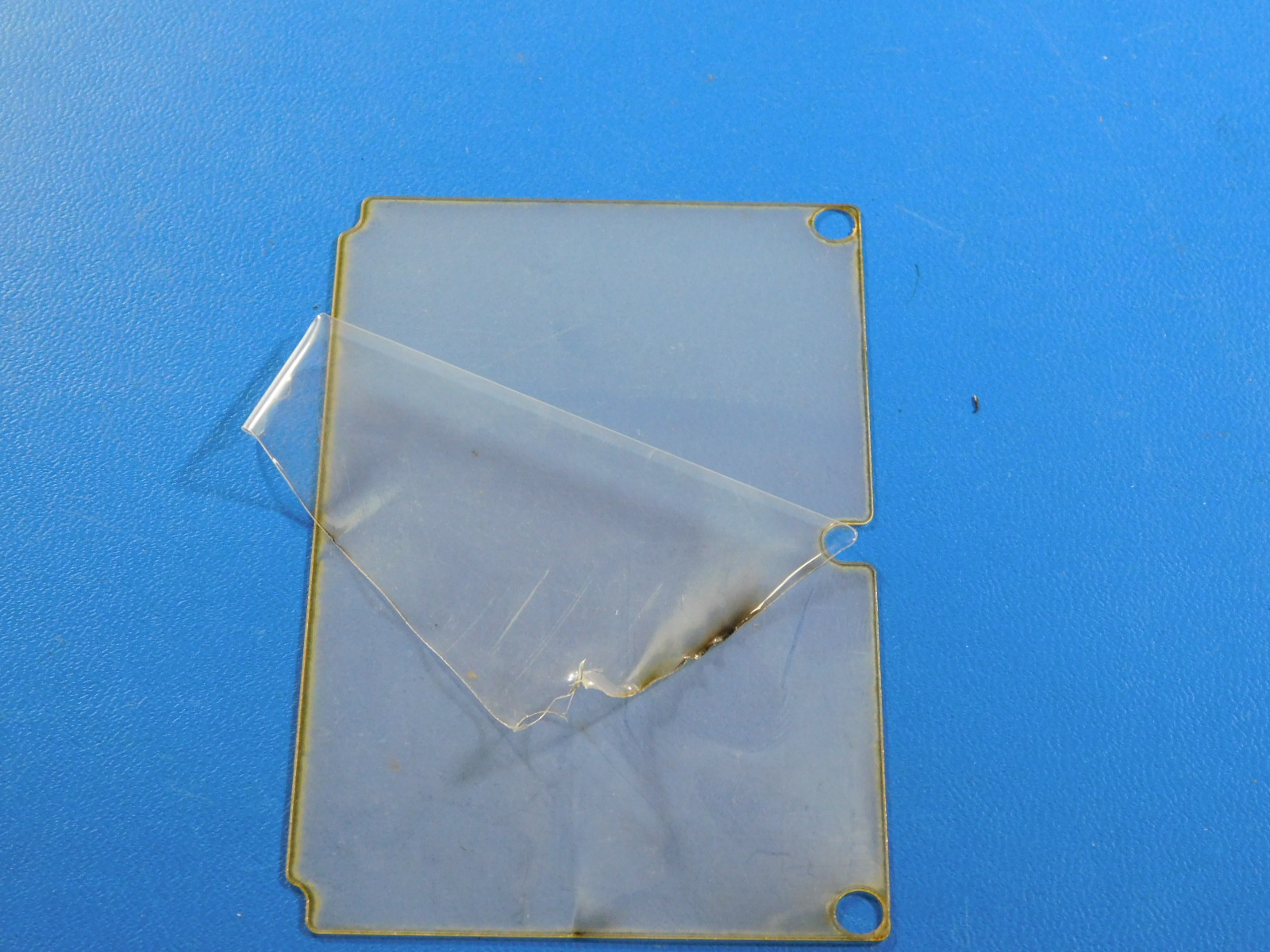
b) Obtain a [PP-FP0183] polycarb LCD cover and carefully remove the film from both sides.
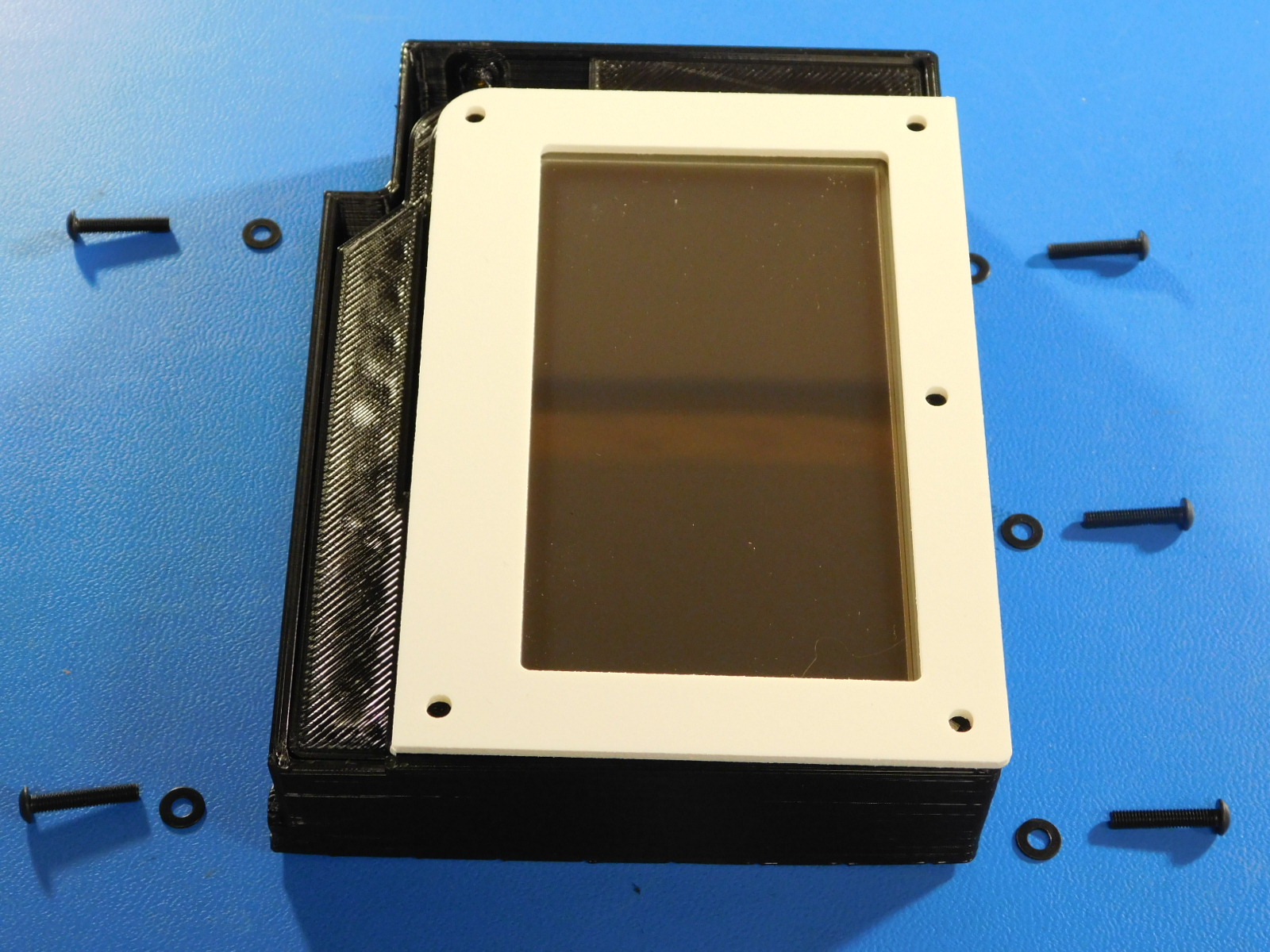
c) Place the polycarb LCD cover on top of the LCD screen so that the side with 3 holes is on the left.
d) Obtain a [PP-FP0174] touchscreen bezel cover and place it over the assembly.
c) Secure with 5x [HD-BT0256] M3x16mm BHCS with washers.
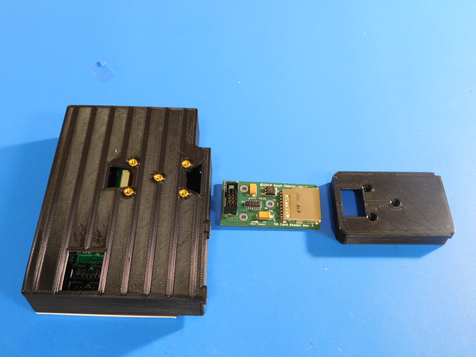
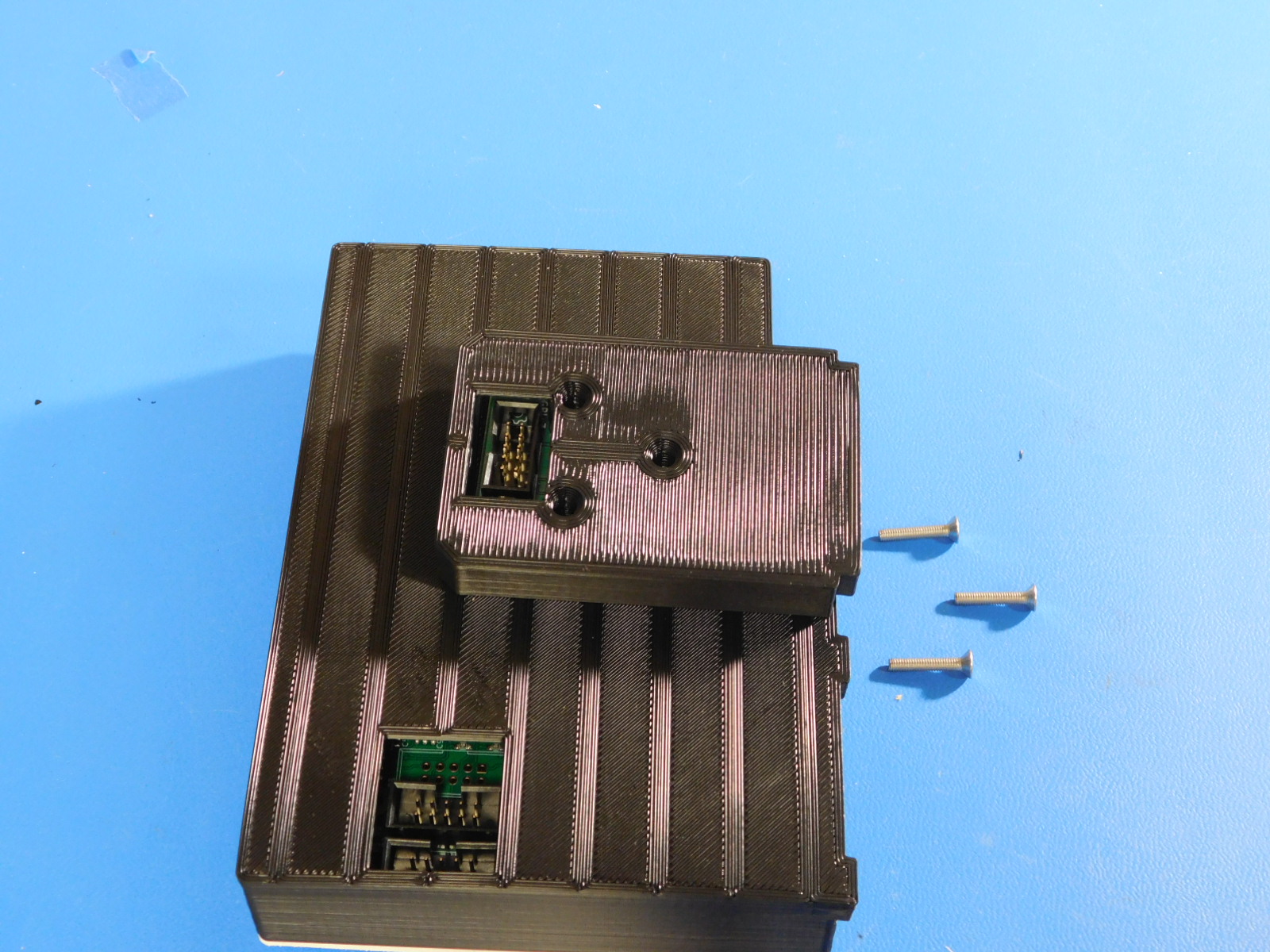
a) Obtain one [PC-BD0124] SC card reader and one [PP-GP0472] SD Mount and orient is as shown.
b) Secure to the back side of the LCD assembly using 3x [HD-BT0082] silver M3x16 FHCS.