Open HardwareAssembly Instructions
Guides for installation and assembly of the LulzBot line of products made by Aleph Objects, Inc.
Guides for installation and assembly of the LulzBot line of products made by Aleph Objects, Inc.
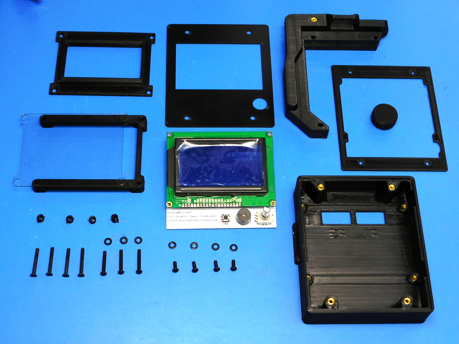
Materials required:
4x- [PP-GP0089] LCD_spacer_v0.4
1x- [PP-GP0324] Mini LCD Bezel
1x- [PP-GP0329] Mini LCD Bezel Spacer
1x- [PP-GP0435] Flexy LCD Knob
1x- [PP-IS0043] Mini LCD Bracket Right V1 with inserts
1x- [PP-IS0056] Mini LCD Case with inserts
4x- [HD-BT0206] M3 x 25 Bolt FHCS, Black-Oxide, Partially Threaded
4x- [HD-BT0137] M3 x 8 Bolt, BHCS, Black-Oxide
3x- [HD-BT0171] Black Oxide Button-Head Socket Cap Screw M3 Size, 20 mm Length, .5 mm Pitch
7x- [HD-WA0038] M3 Black Oxide washer
1x- [PC-AS0056] LCD LB_GLCD
1x- [PC-AS0041] Plastic Laser Cut LCD Cover
1x- [PP-MP0215] LCD Cover, HIPS, Mini 2
1x- [PP-GP0339] LCD cover spacer
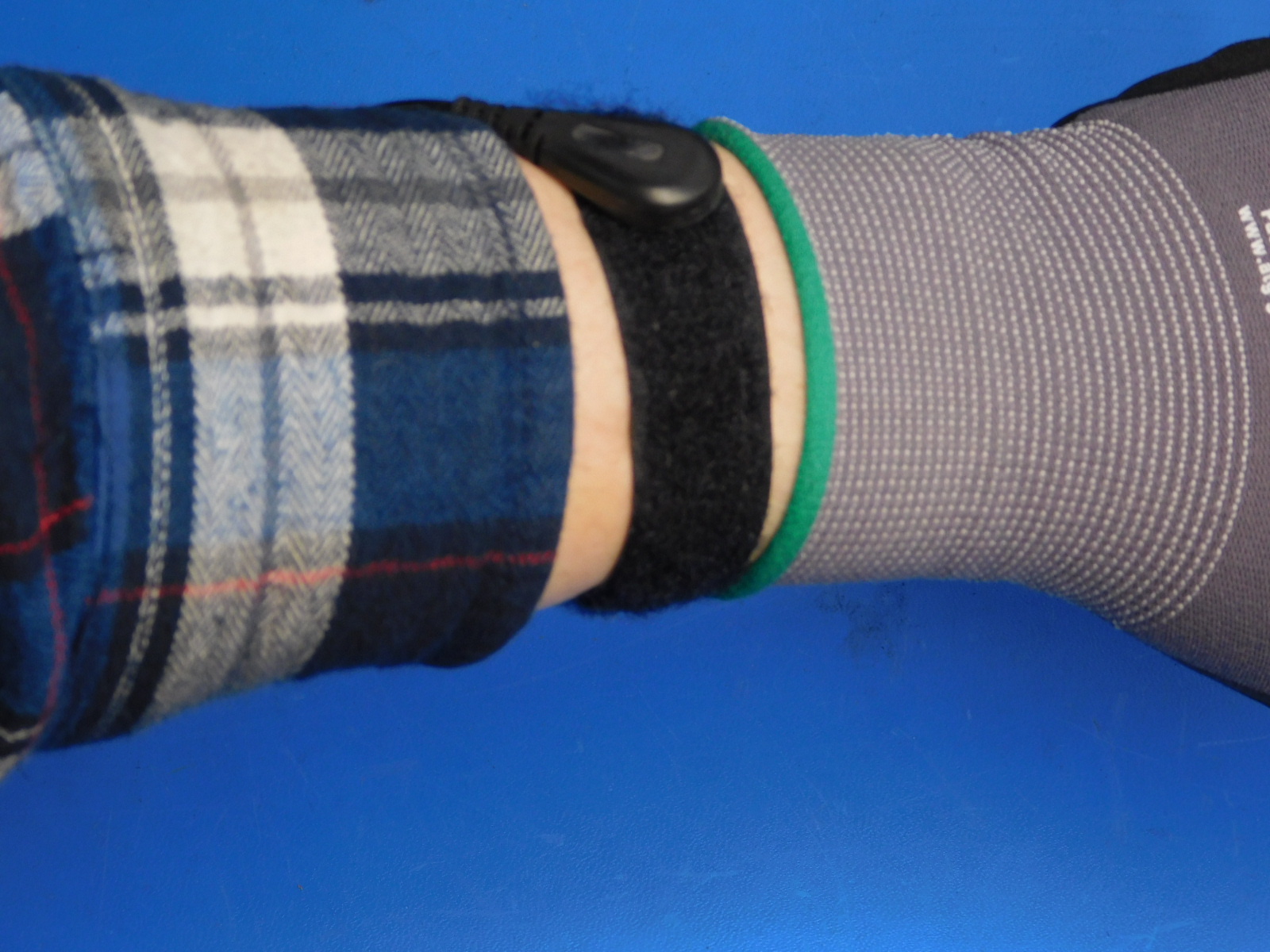
To prevent static damage to the LCD controller, ground yourself with a grounding strap. Ensure the metal button inside the wrist strap makes contact with your bare skin and that the wrist strap lead is connected properly to earth ground.
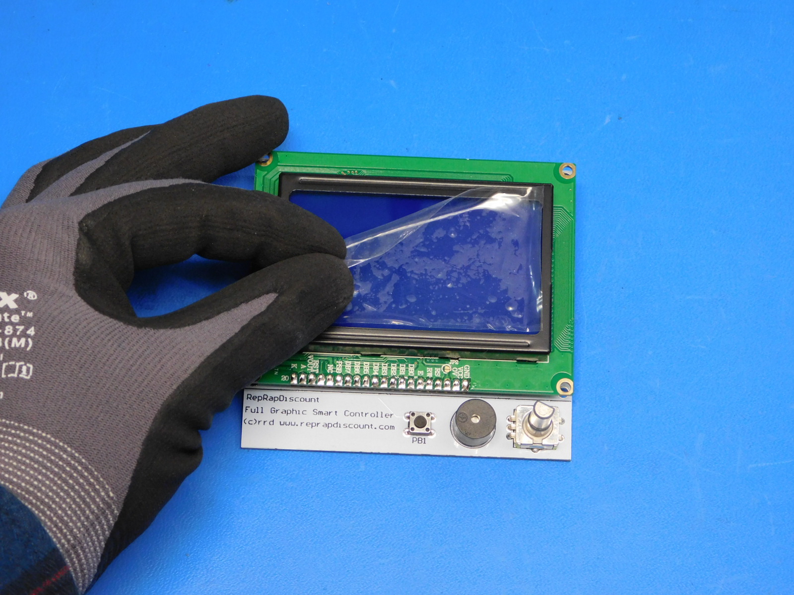
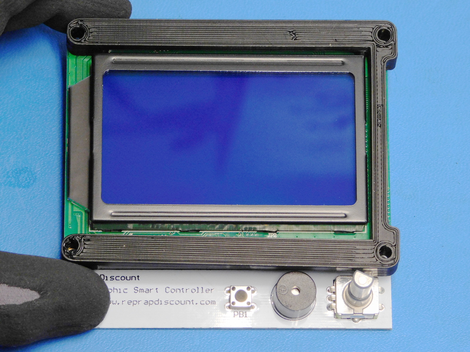
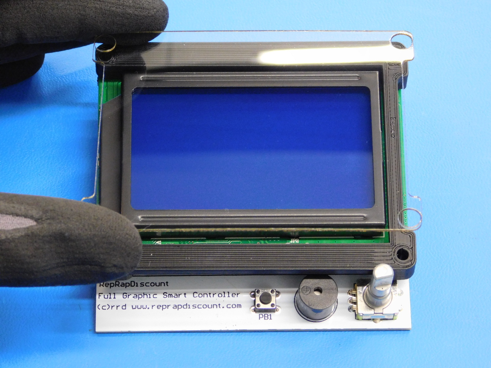
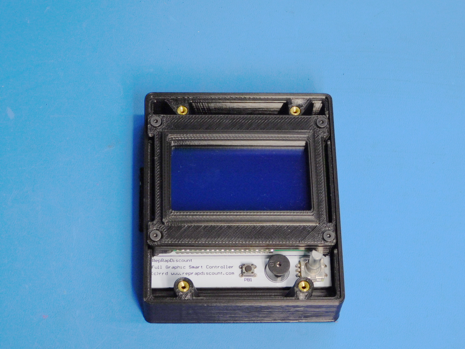
First, remove the plastic protector from the LCD display [PC-AS0056].
This may be set aside for later use (sticks well to the side of your workstation's monitor)
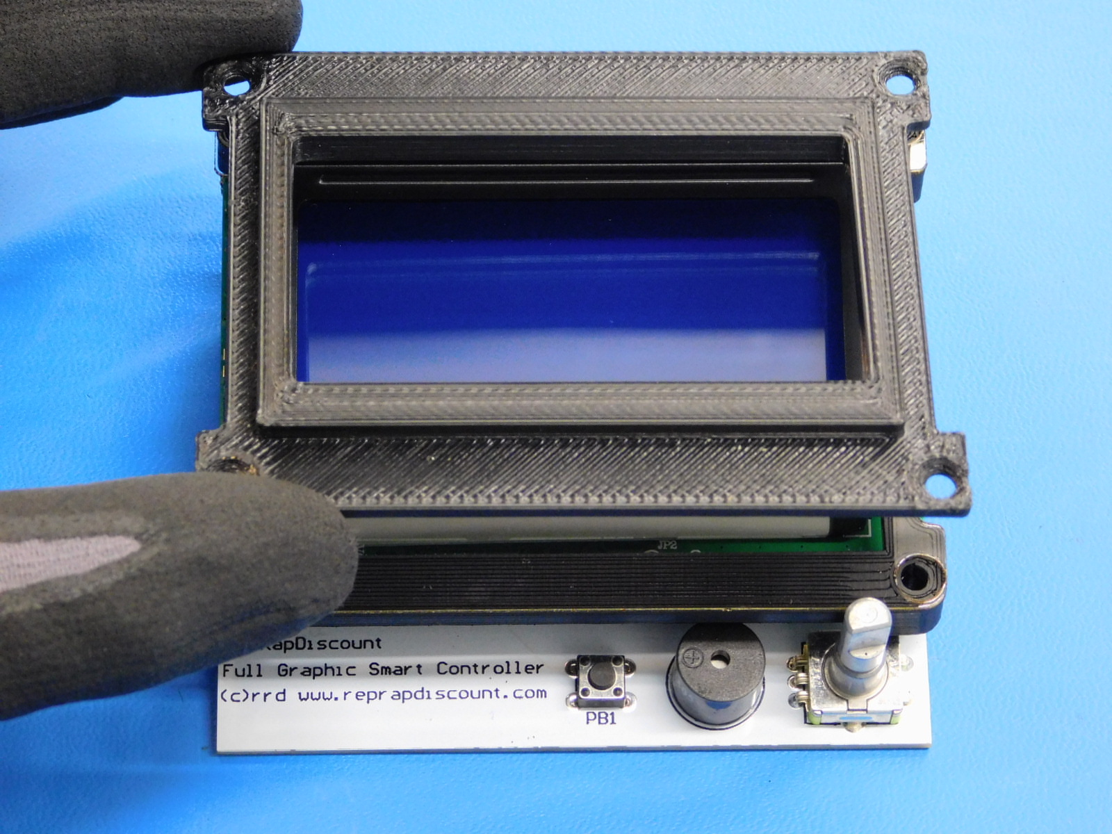
Place the LCD Bezel Spacer [PP-GP0329] over the LCD display as shown.
Remove protective backing from the Plastic Laser Cut LCD Cover [PC-AS0041] and place on top of the LCD Bezel Spacer [PP-GP0329] as shown.
Place the LCD Bezel [PP-GP0324] on top of the Plastic Laser Cut LCD Cover [PC-AS0041], as pictured.
Install four M3x25 FHCS [HD-BT0206] into the holes at each corner of the LCD Bezel [PP-GP0324]
Install an LCD Spacer [PP-GP0089] into each corner of the LCD Display [PC-BD0057] as shown;
Lift the M3x25 FHCS in that corner, insert the LCD Spacer [PP-GP0089] in between the boards as pictured, and push the flat head screw through it to hold it in place.
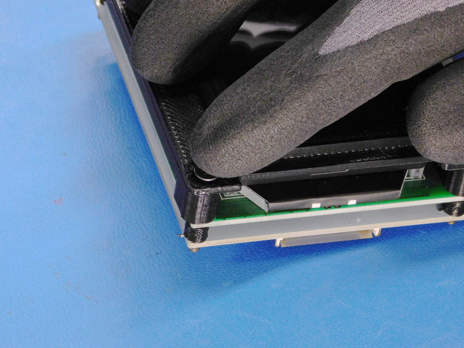
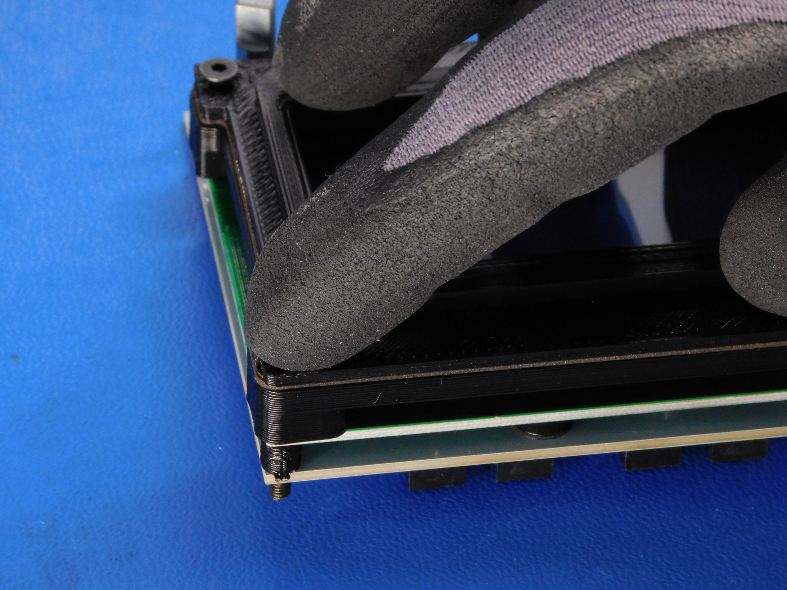
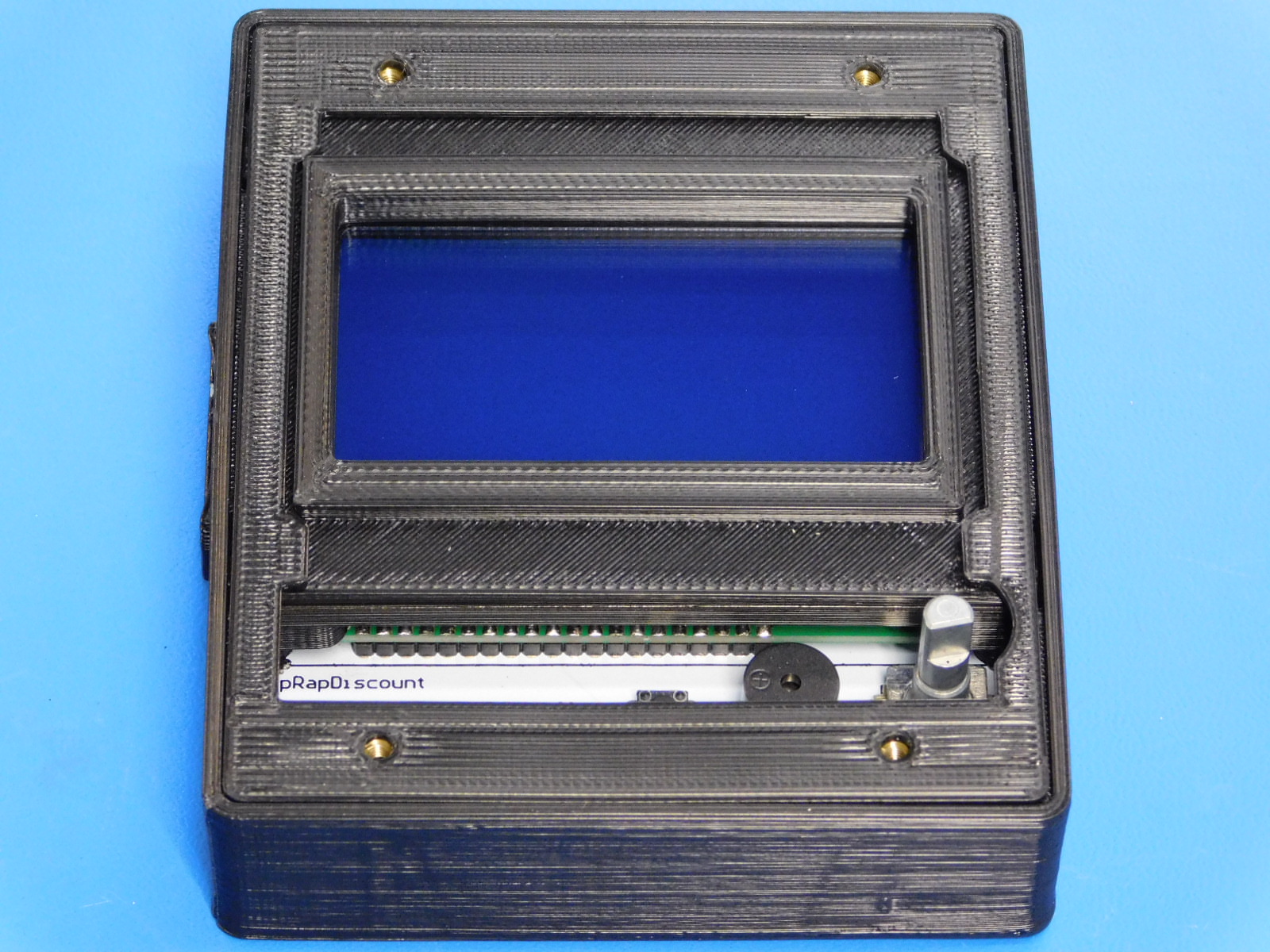
Grasp the LCD Display (assembled with spacers, and fasteners in place) and carefully work it into the LCD Case [PP-IS0056]
It is helpful to lead with the left side as pictured and then carefully fit the right side around the lip inside the case.
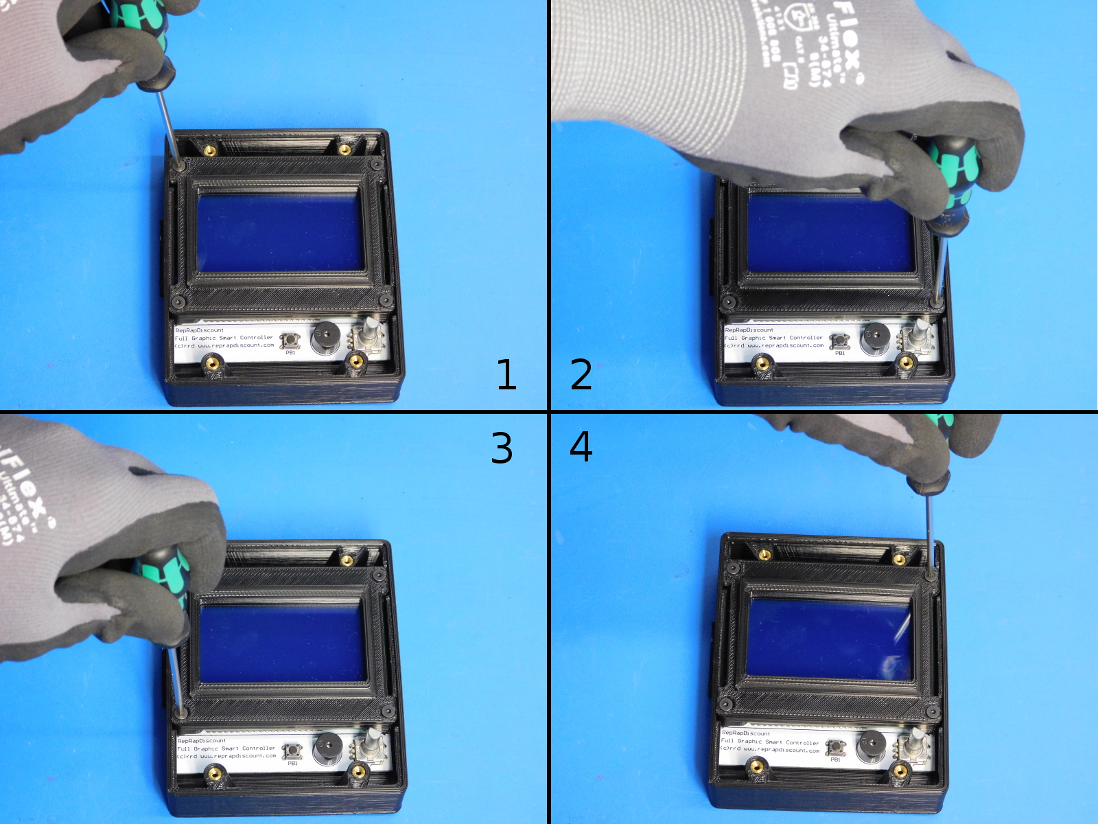
Using a crisscross pattern, thread each flat head screw into the inserts on the bottom of the case.
Ensure all four screws have started properly before beginning to tighten.
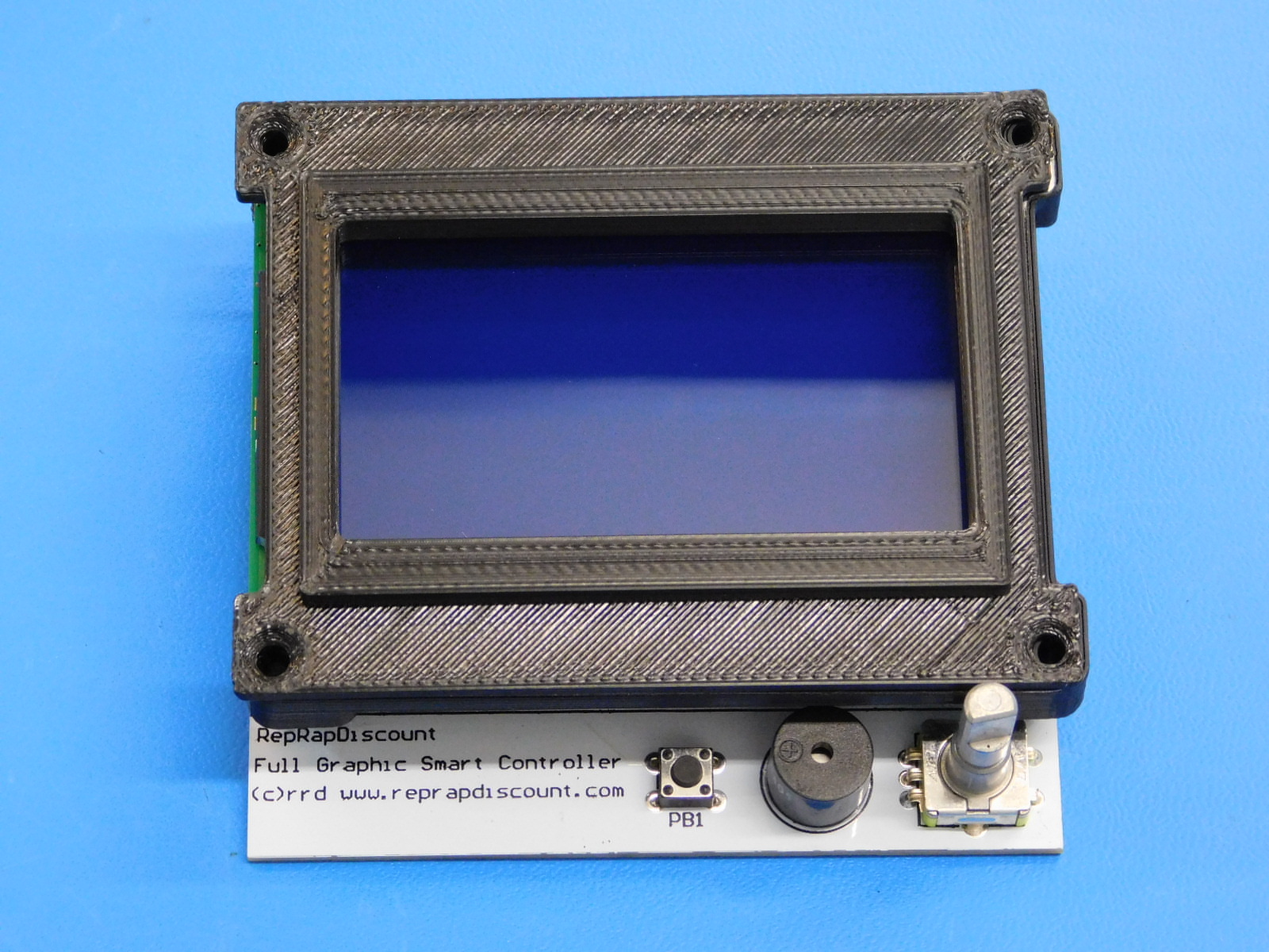
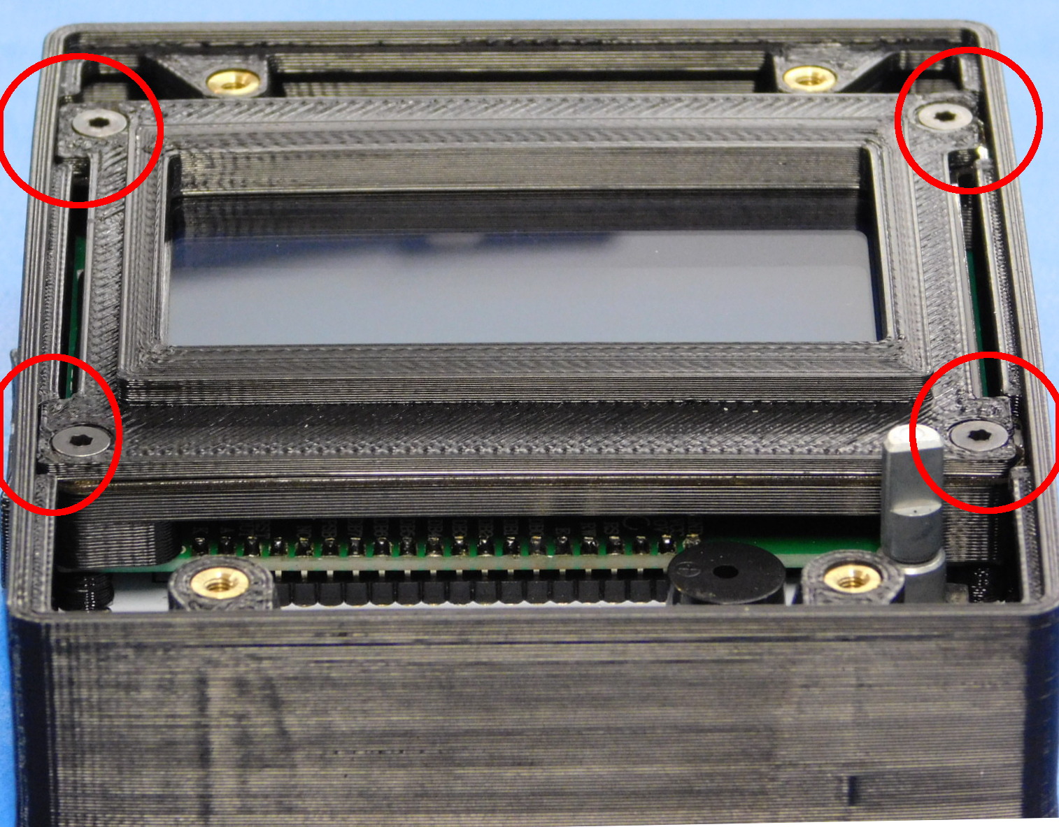
Continue to tighten using a crisscross pattern until the edges of the LCD Bezel are at level with the lip inside the case; see [reference#1]
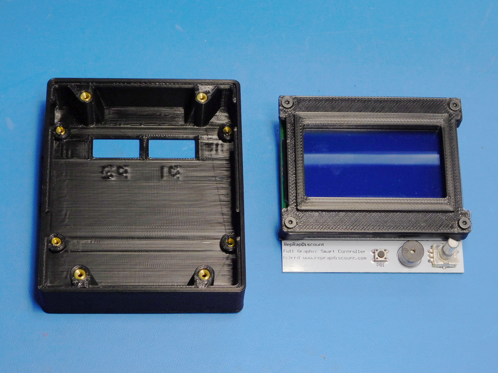
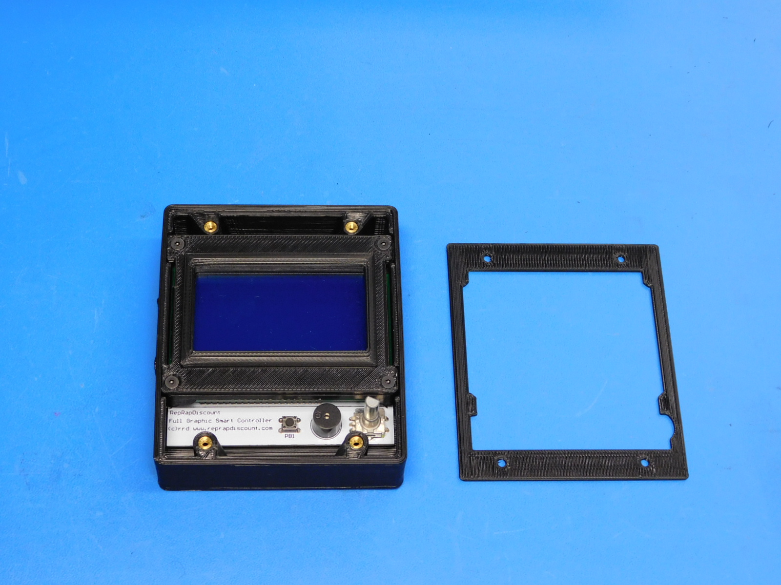
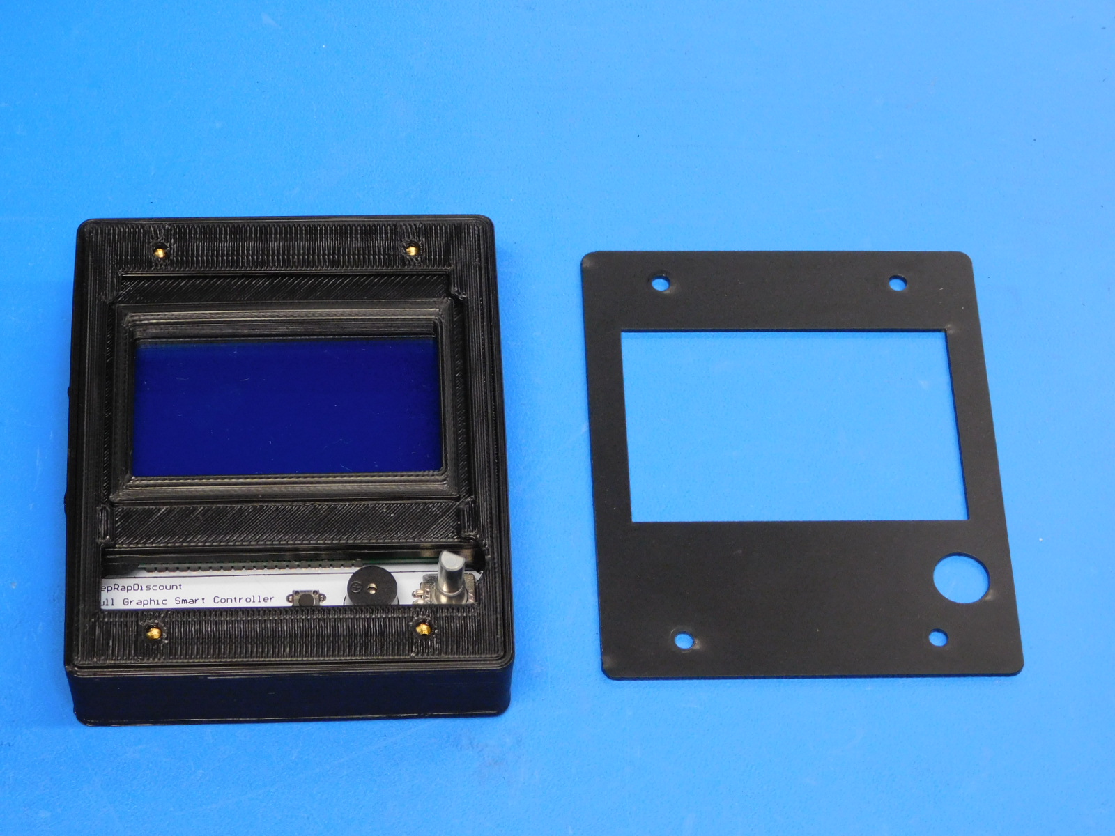
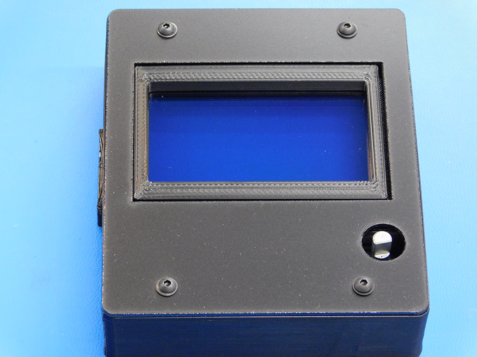
Place the LCD Cover Spacer [PP-GP0339] on top of the assembly, oriented as pictured.
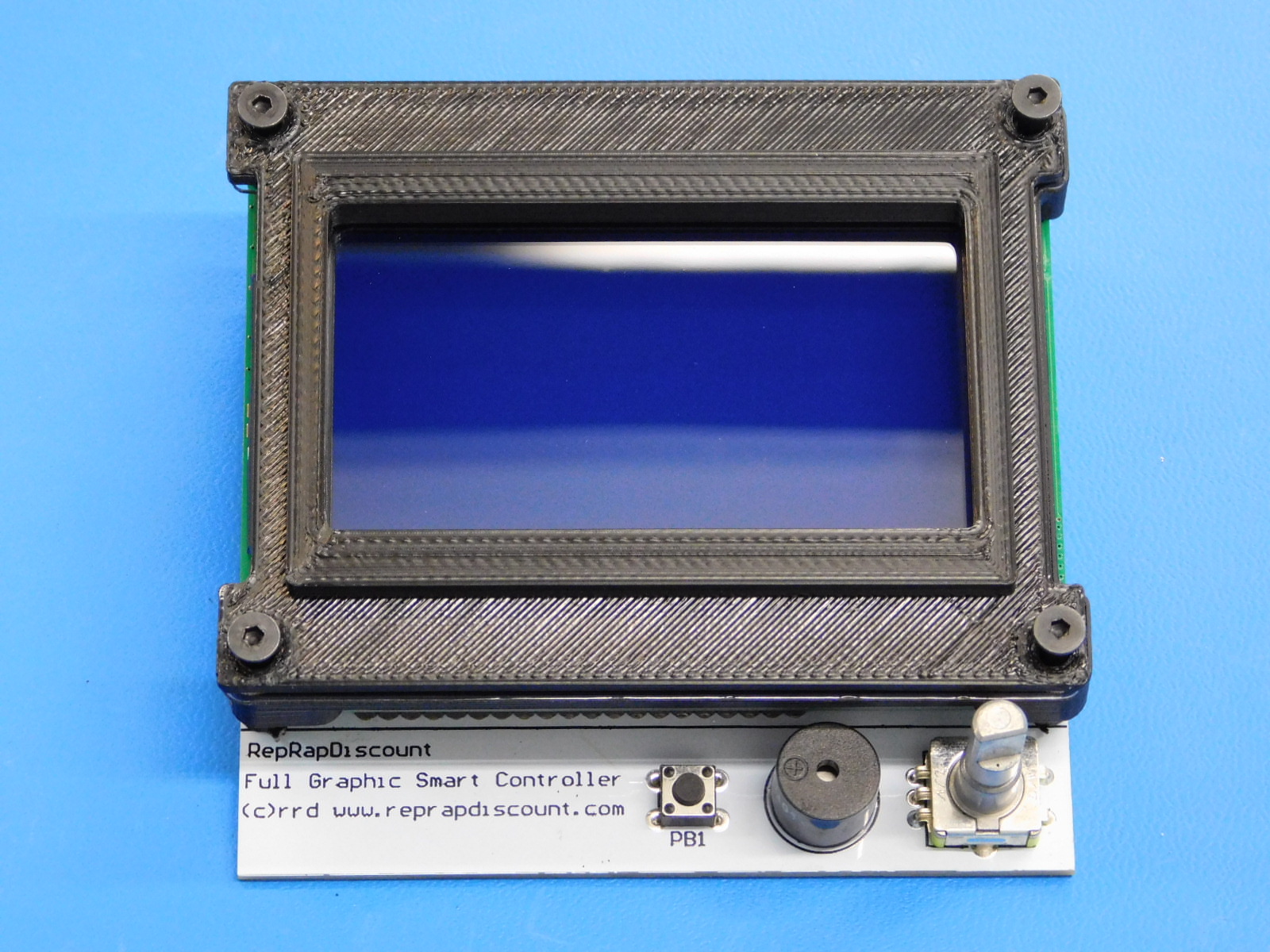
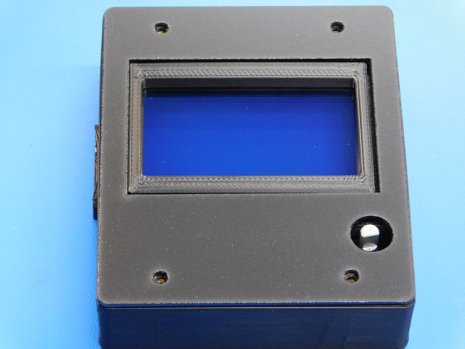
Place the LCD Cover [PP-MP0215] over the assembly as pictured.
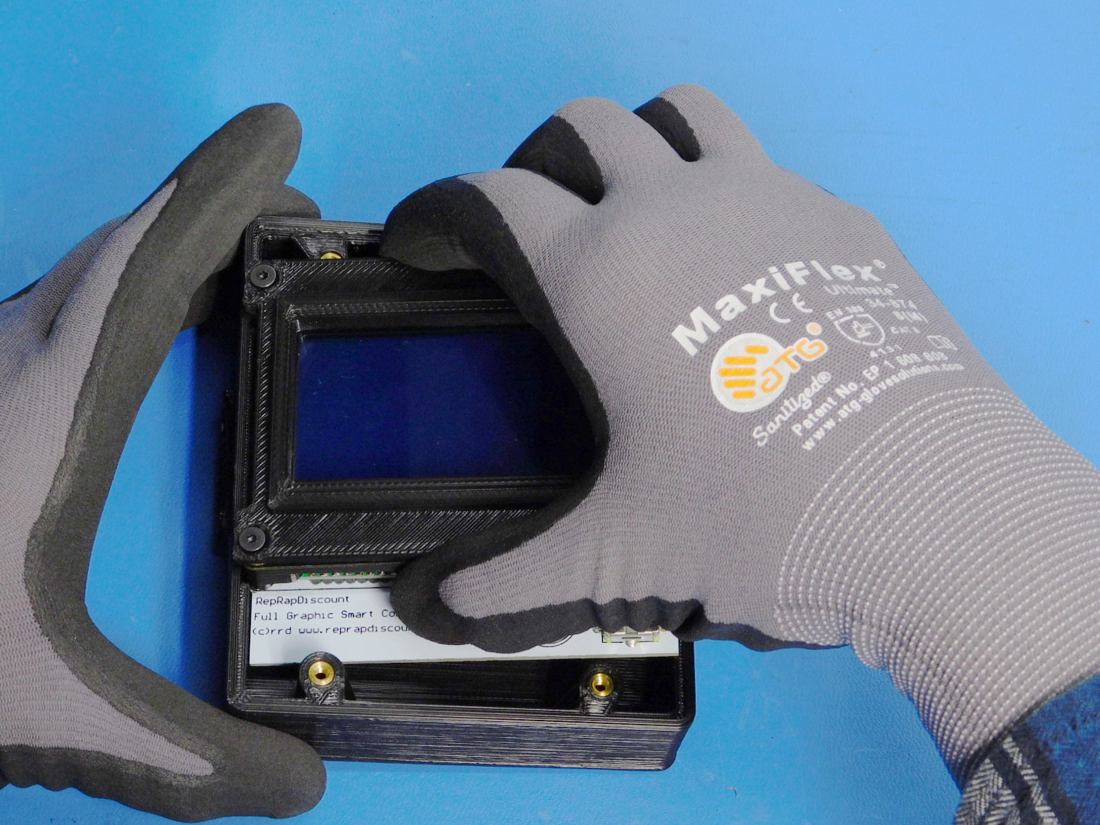
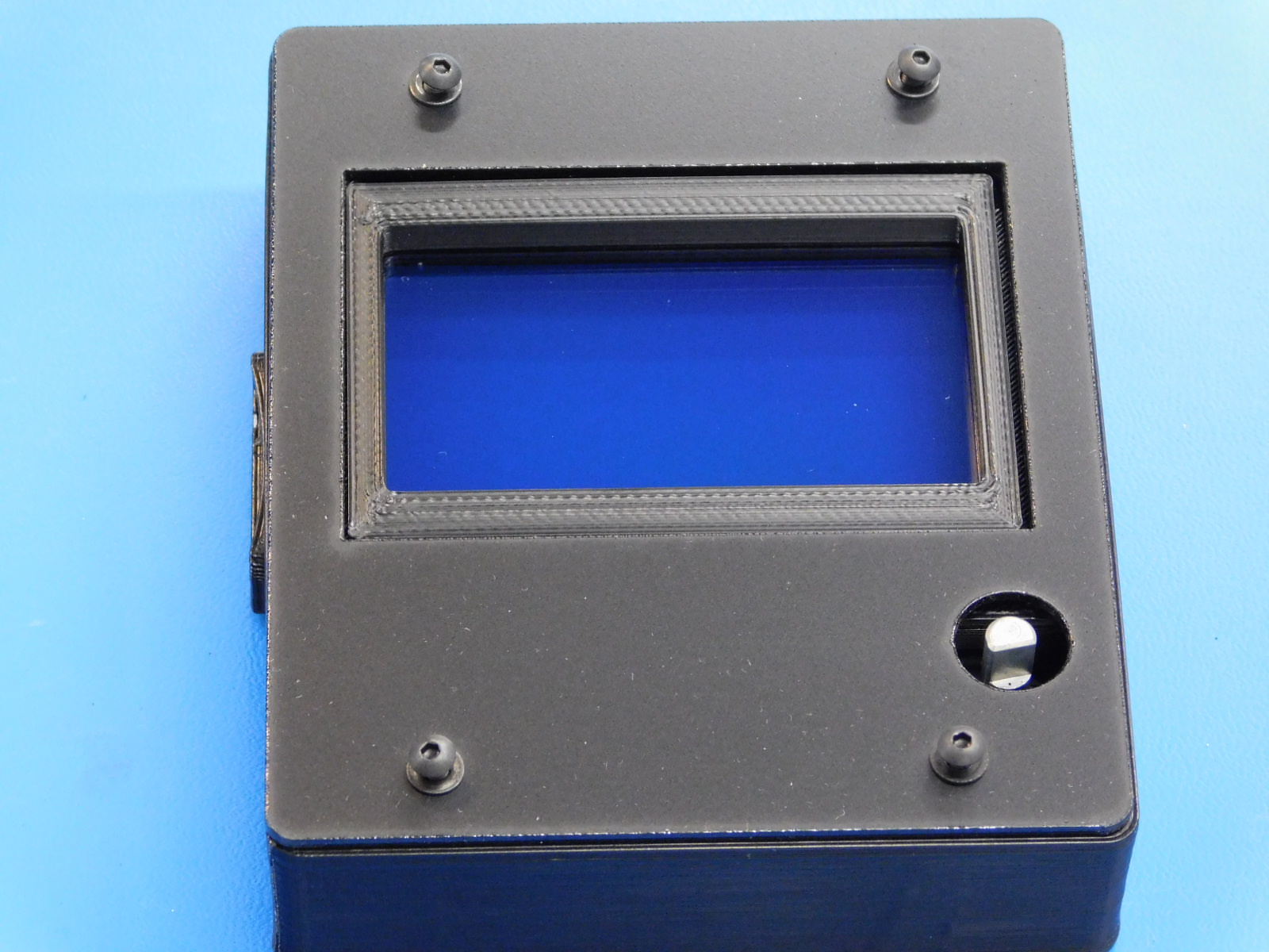
Install four M3x8 BHCS [HD-BT0137] with washers [HD-WA0038] into the four M3 holes on the LCD Cover [PP-MP0215]
Before tightening, center the LCD cover within the outer four edges of the LCD case for best appearance. Make sure there is enough clearance for the LCD knob and that the LCD knob post is centered in the hole in the cover. Tighten until the LCD Cover lays flat around the edges of the case.
Do not over tighten, this will cause the cover to bow inwards near the screw heads.
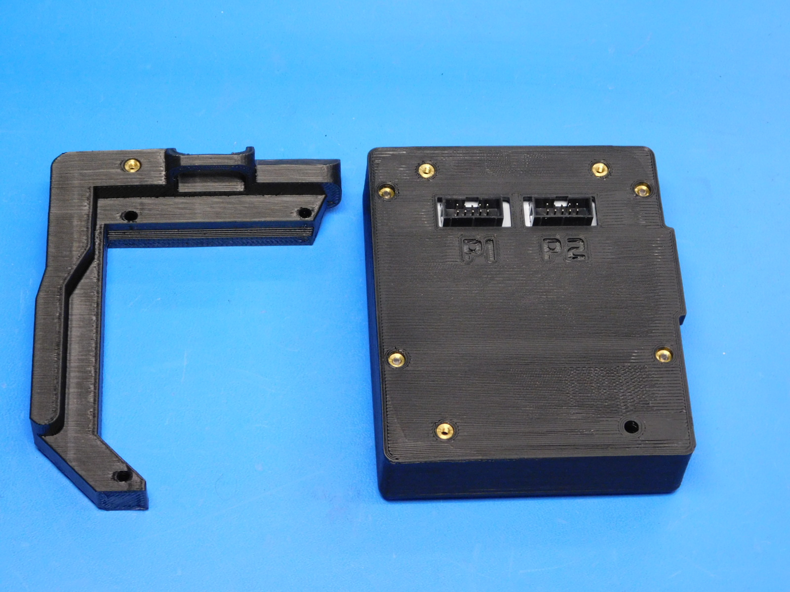
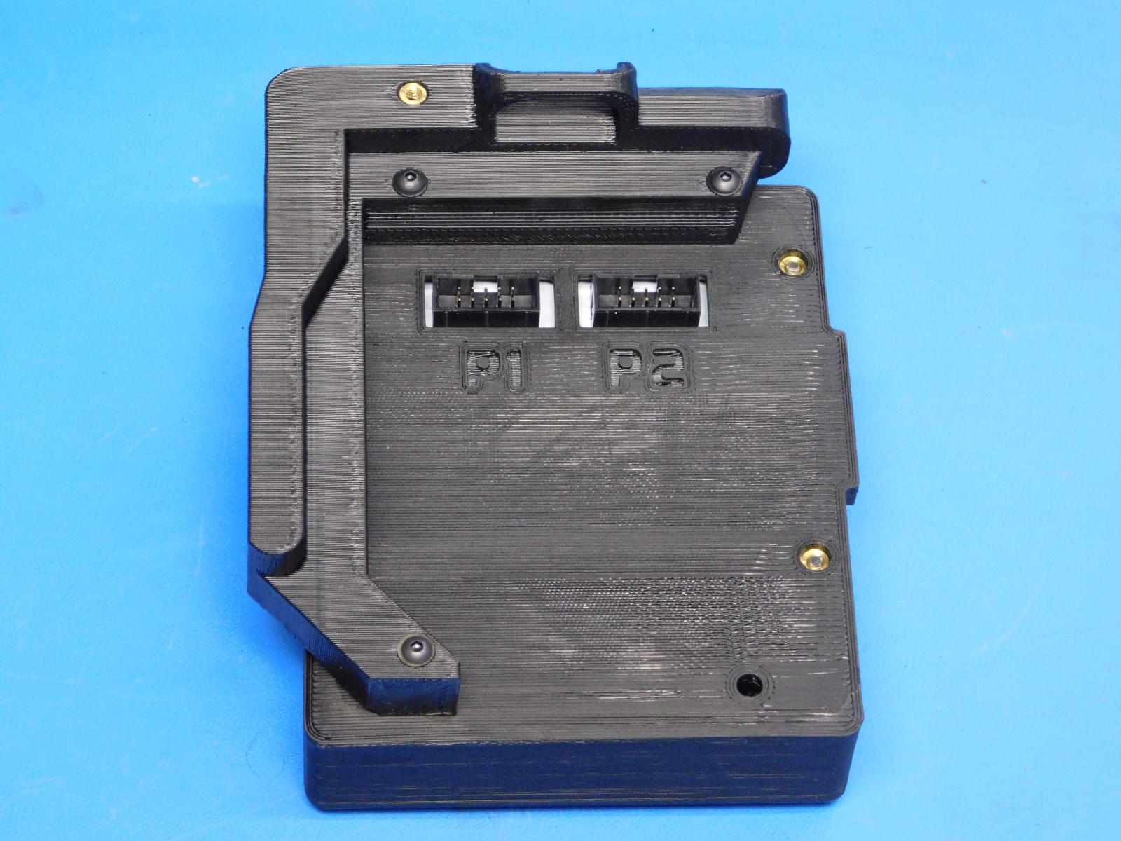
To install the LCD Bracket [PP-IS0043] flip the LCD Case over so that it lays face down on the workbench
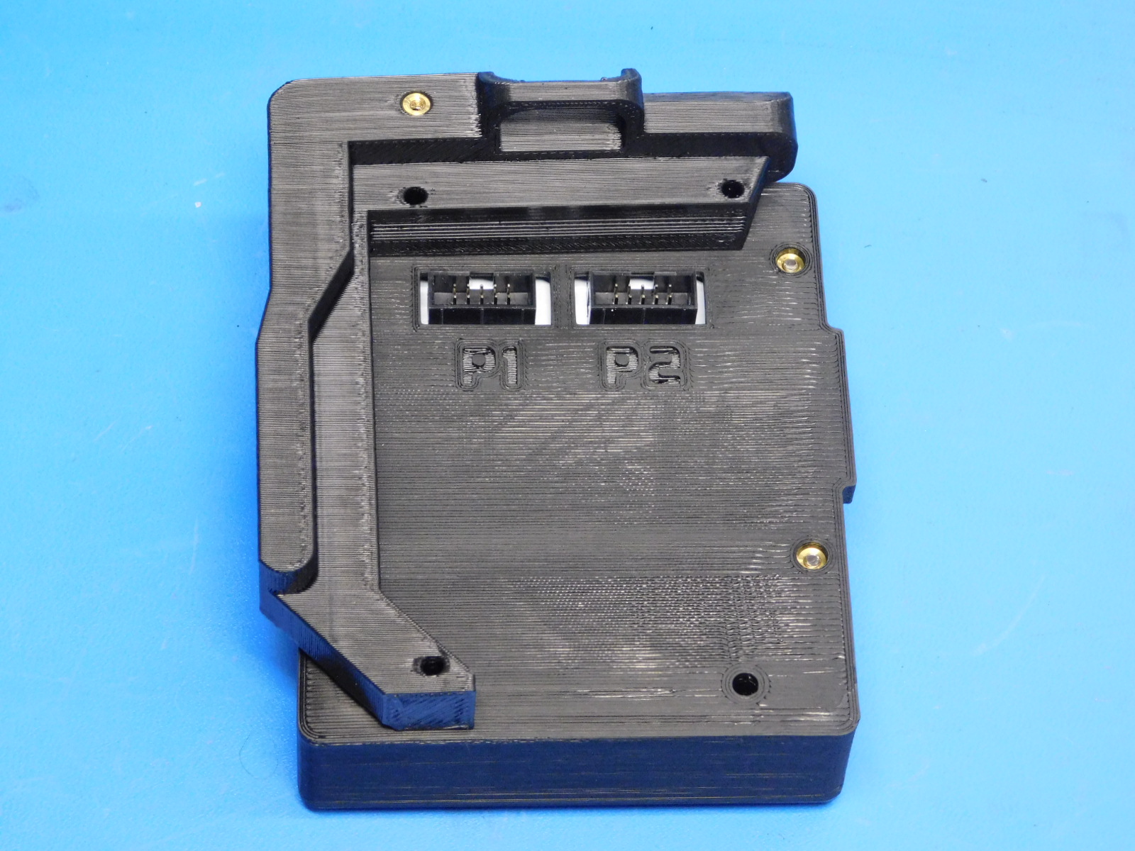
Line up the holes in the bracket with the inserts on the back of the case as shown.
Secure using 3 M3x20 BHCS [HD-BT0171] with washers [HD-WA0038]
Torque to 5in*lbs
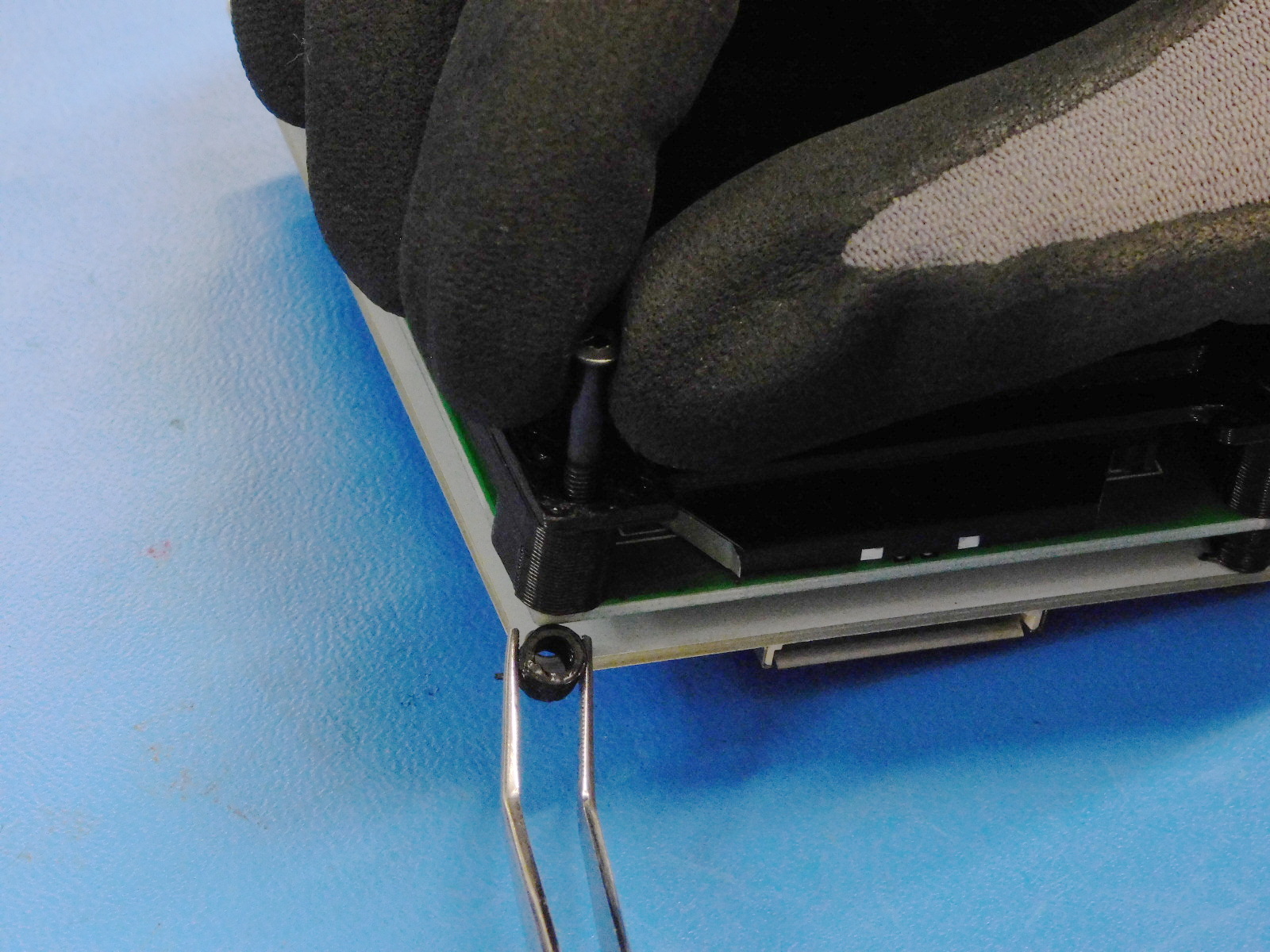
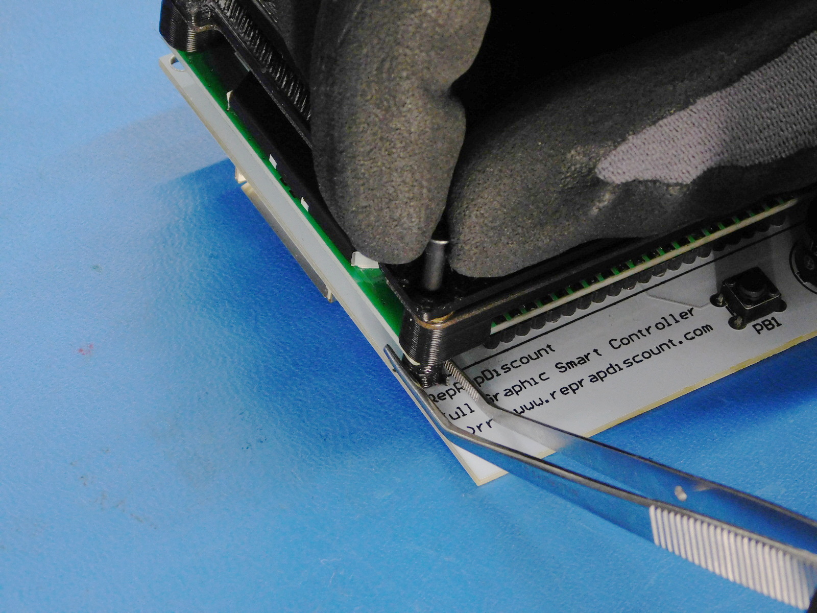
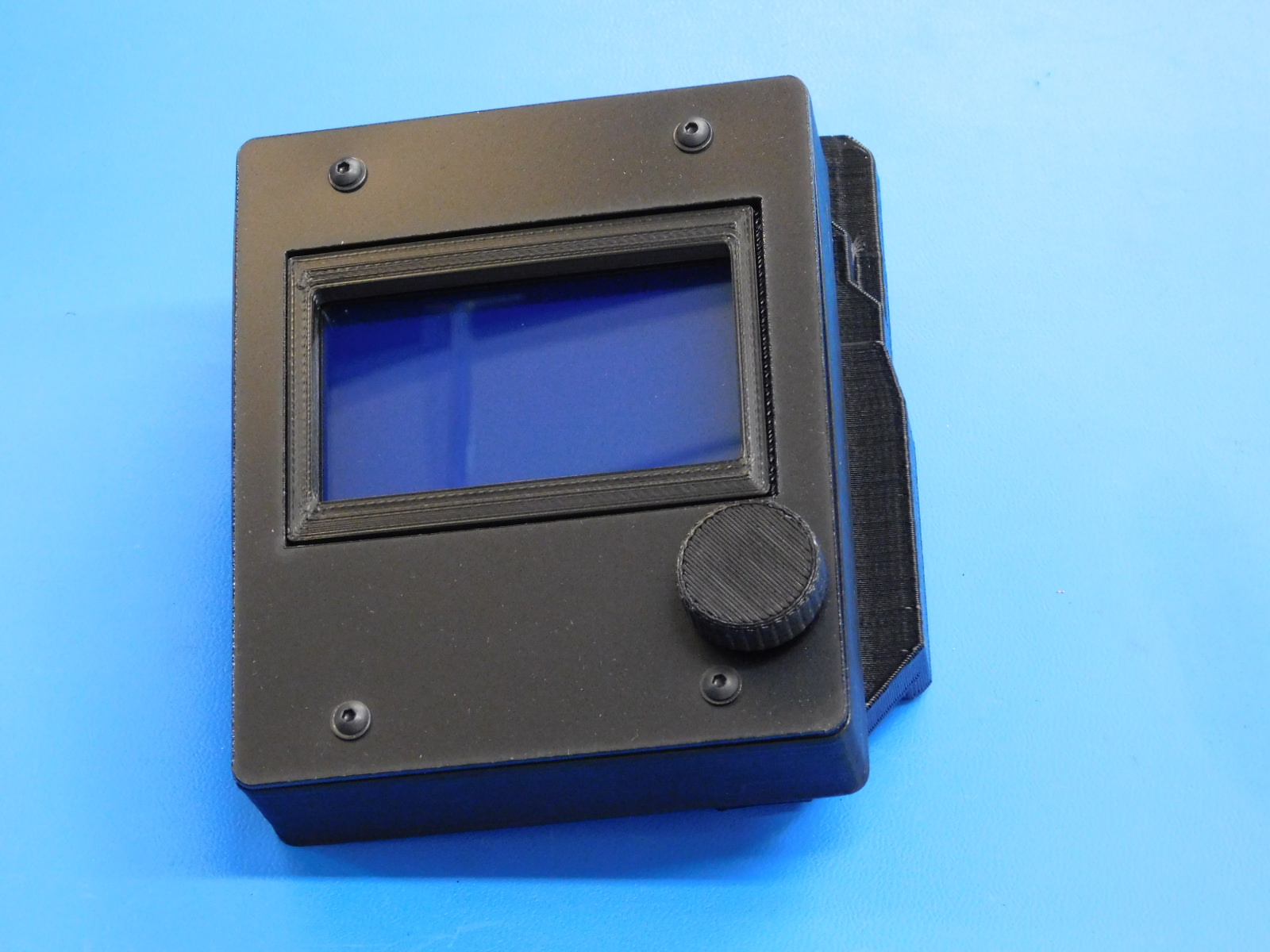
Install the Flexy LCD Knob [PP-GP0435]
Ensure the Knob fits properly and is able to be pressed and clicked repeatedly.
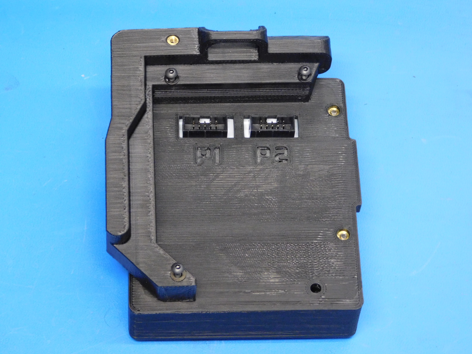
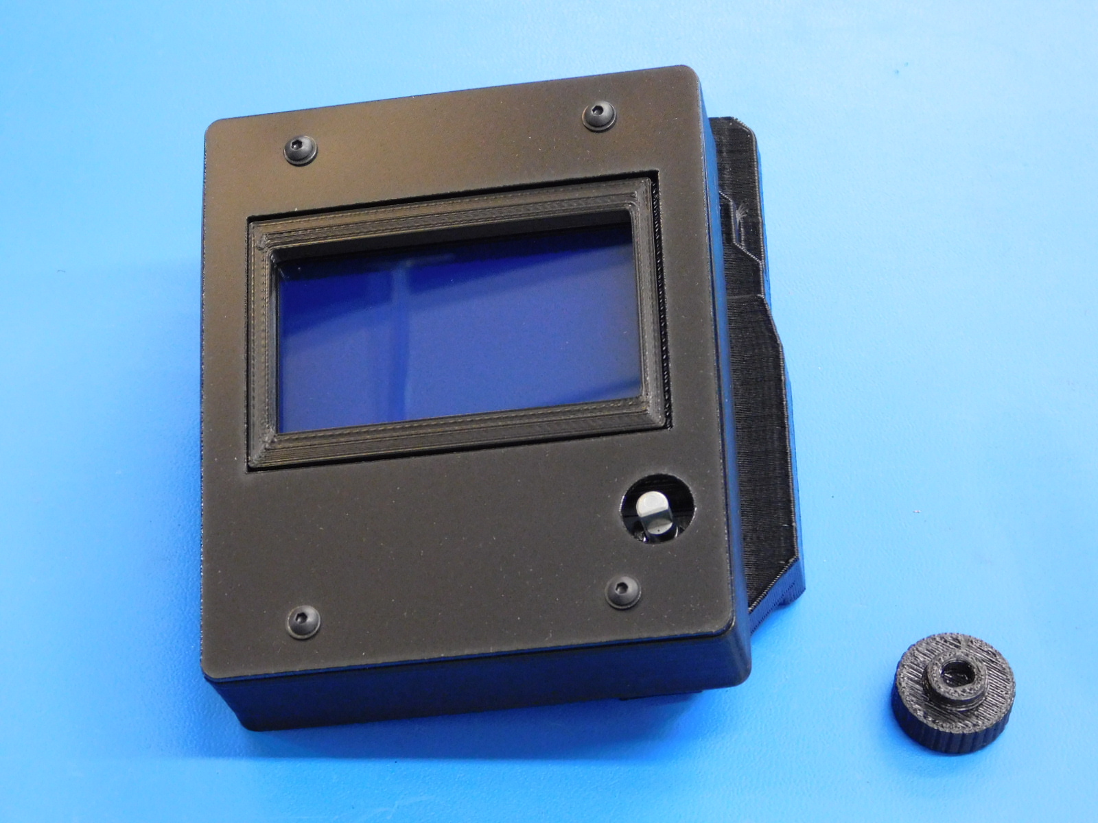
If available, place the screen protector removed in step 3 over the LCD Display to protect it during assembly.
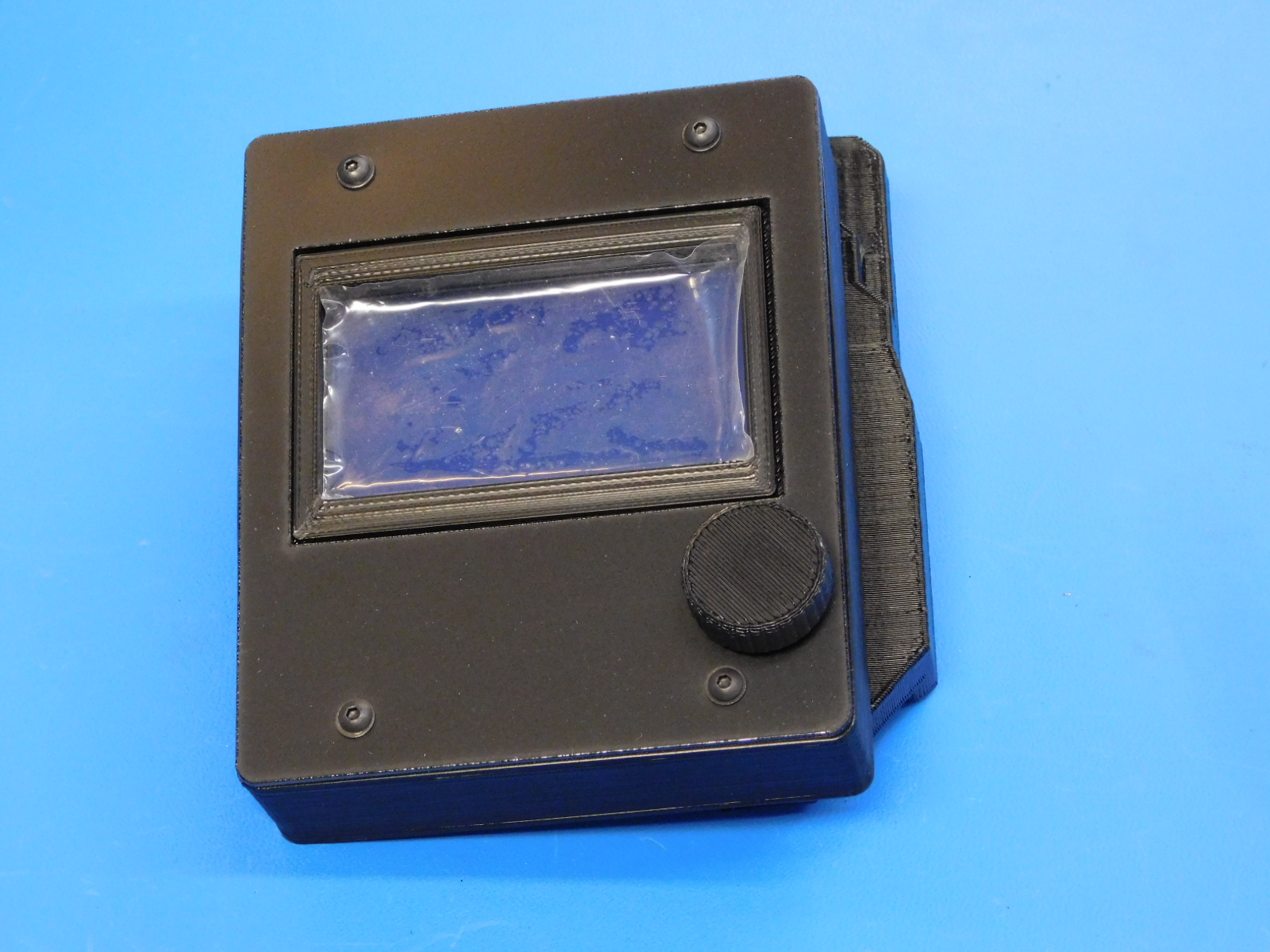
Inspect your work and verify it matches the picture show at right.