Open HardwareAssembly Instructions
Guides for installation and assembly of the LulzBot line of products made by Aleph Objects, Inc.
Guides for installation and assembly of the LulzBot line of products made by Aleph Objects, Inc.
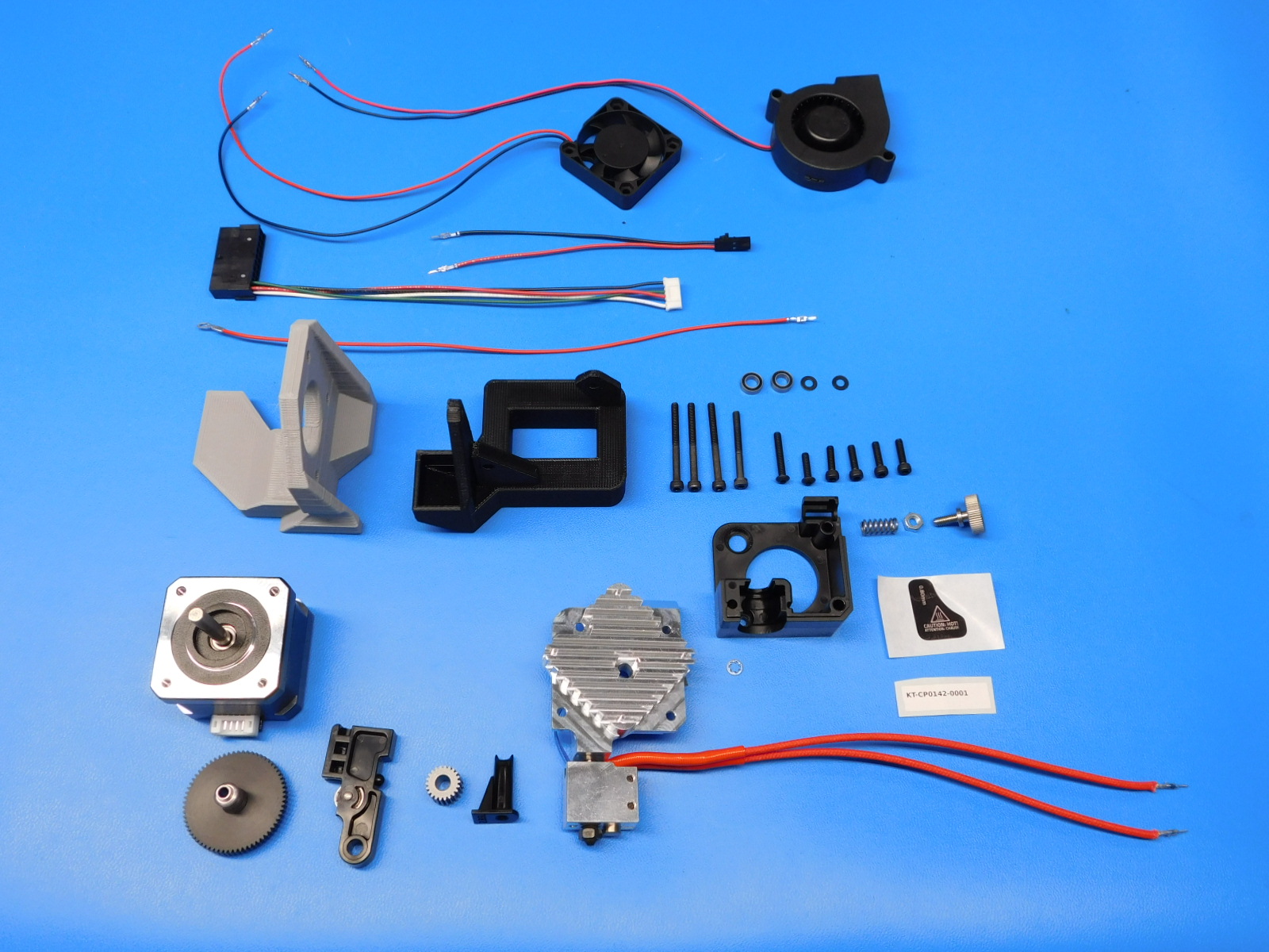
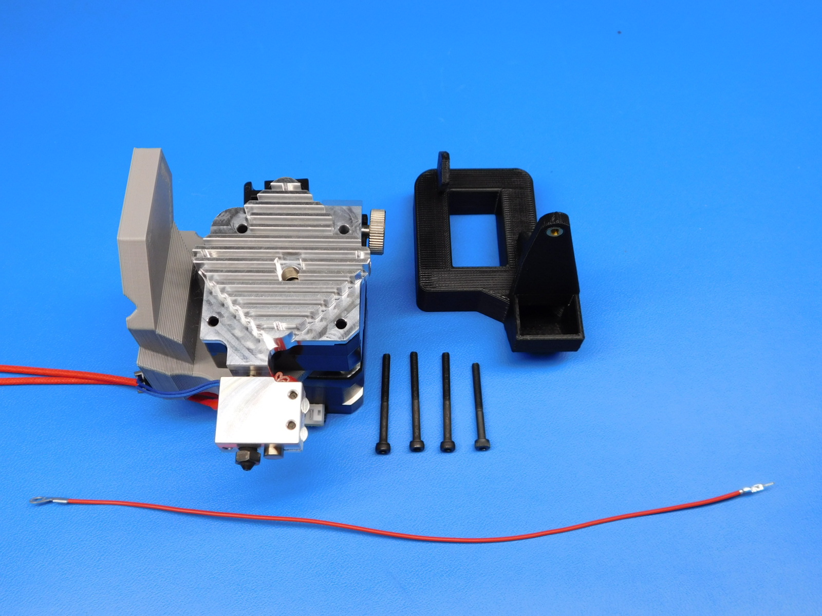
Gather the required materials:
1x- [AS-HE0034] v2 Aero HS Hotend Assembly
1x- [AS-CB0063] 220mm HotEnd Ground Wire
1x- [AS-CB0062] Blower fan Harness, 250mm
1x- [AS-CB0061] Extruder Motor Harness, Mini2
1x- [AS-CB0064] Heatsink fan Harness, 220mm
1x- [AS-CB0066] Thermistor Harness, 120mm
1x- [DC-LB0167] Caution Hot Symbol Size, 0.80mm
1x- [PP-IS0070] Extruder Mount with Inserts, v2 Aero Micro
1x- [EL-MT0029] NEMA 17 Full Height Stepper Motor, Moons
4x- [HD-BT0039] Socket Head Cap Screw, Alloy Steel, M3 Thread, 12MM Length, 0.50MM Pitch
1x- [HD-BT0042] Socket Head Cap Screw, Alloy Steel, M3 Thread, 30MM Length, 0.50MM Pitch
3x- [HD-BT0043] Socket Head Cap Screw, Alloy Steel, M3 Thread, 35MM Length, 0.50MM Pitch
1x- [HD-BT0146] M3 x 12 BHCS, Black Oxide, Class 10.9 Steel
1x- [HD-BT0171] Black Oxide Steel Button-Head Screw M3 Size, 20 mm Length, .5 mm Pitch
1x- [HD-BT0197] M4 Thumb Screw for Aero
1x- [HD-MS0430] Idler Spring for Aero
2x- [HD-MS0446] MR95-2RS Radial Ball Bearing Double Sealed Bore Dia. 5mm OD 9mm Width 3mm
1x- [HD-NT0011] M4 Nut, Steel, Zinc Plated
1x- [HD-WA0027] Stainless Steel Internal-Tooth Lock Washer, M3 Screw Size, 6MM OD, .4MM Min Thick
1x- [HD-WA0038] Black-Oxide 18-8 Steel Flat Washer, M3 Screw Size, 3.2mm ID, 7.0mm OD
1x- [PP-FP0135] E3D Aero Idler Lever
1x- [PP-FP0136] E3D Mirrored Aero 2.85mm Filament Guide
1x- [PP-FP0154] Titan Extruder Hobb (Hardened Stainless Steel)
1x- [PP-MP0204] Aero Mirrored Body w/ Threaded Insert
1x- [PP-MP0282] E3D Aero Steel Pinion Gear w/ set screw
1x- [PP-GP0334] Blower Shroud
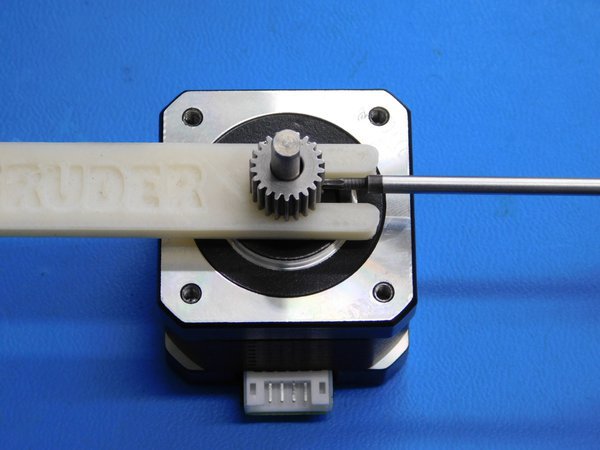
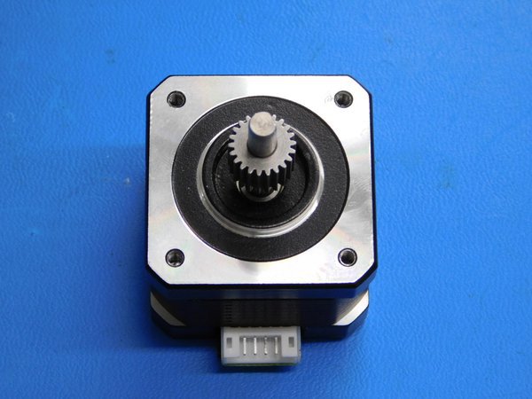
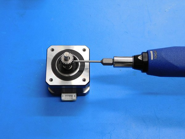
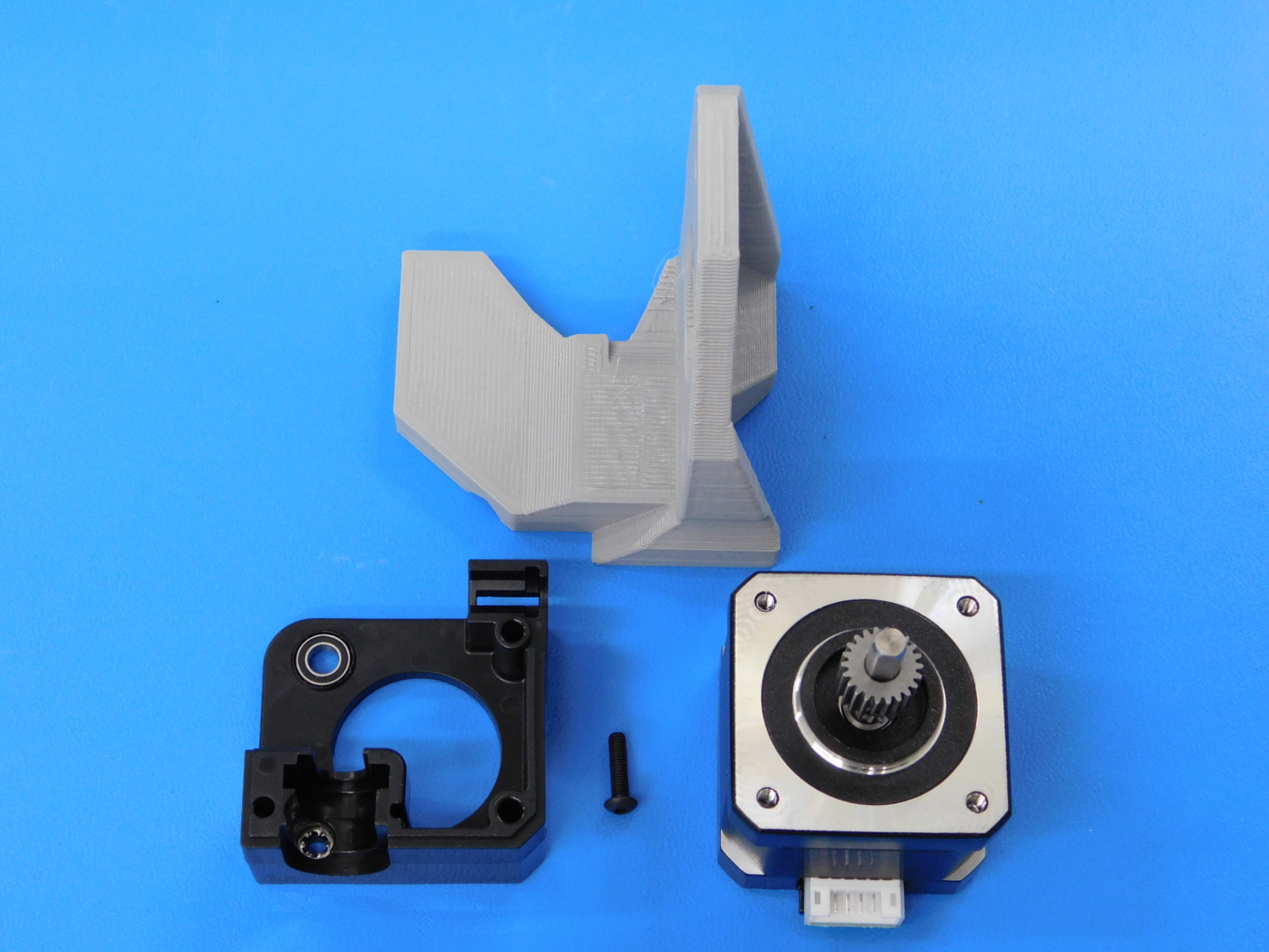
Install the drive gear [PP-MP0282] onto the flat side of the motor shaft [EL-MT0029] using the printed drive gear spacer jig as shown. Torque the set screw to 5 in * lbs.
A set screw should come pre-installed in the gear, if not, ensure an M3x3 set screw is used. Set screws of any greater length will interfere with the larger gear during operation.
Thickness of the printed spacer is 5mm
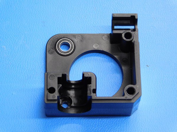
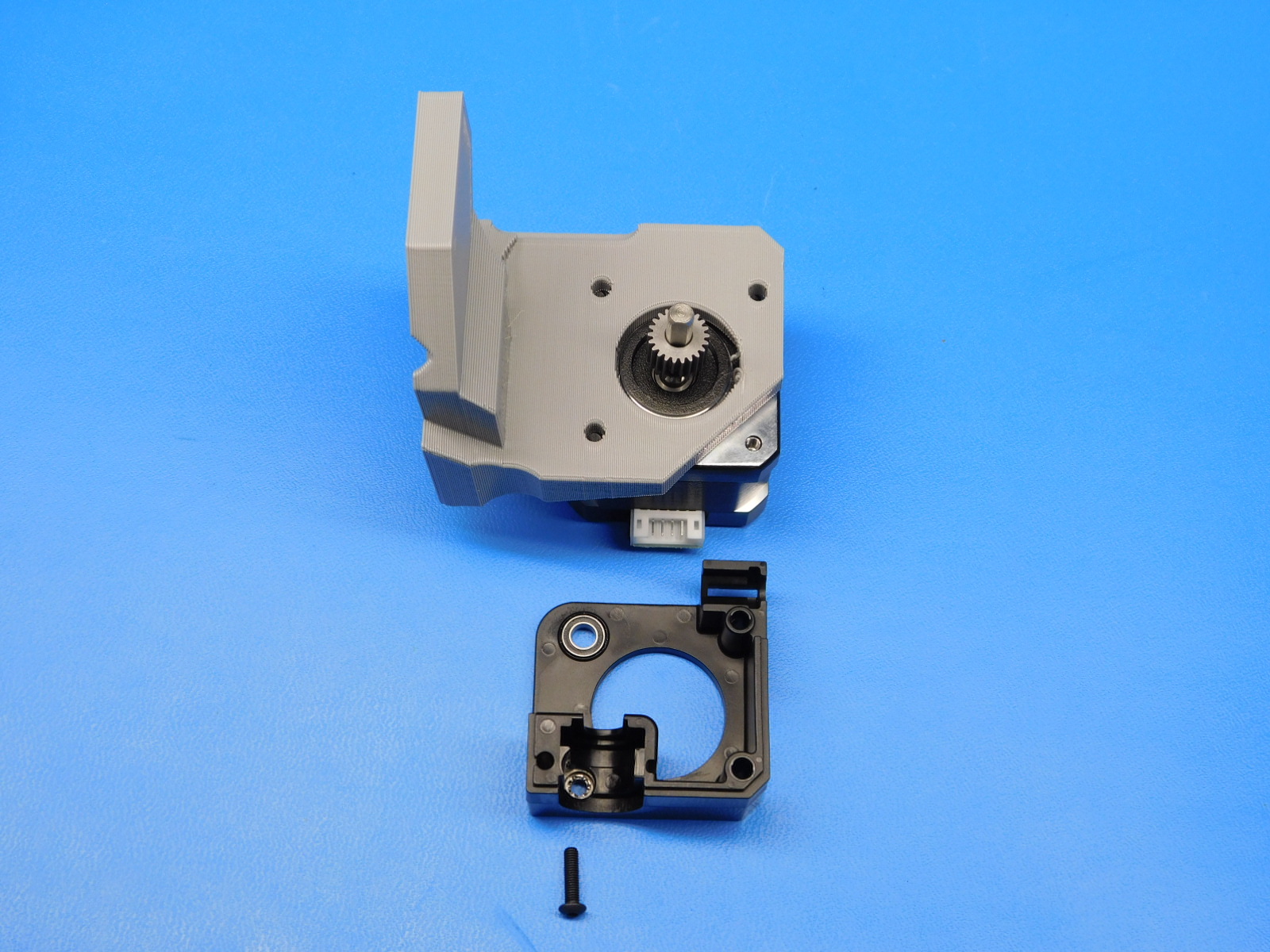
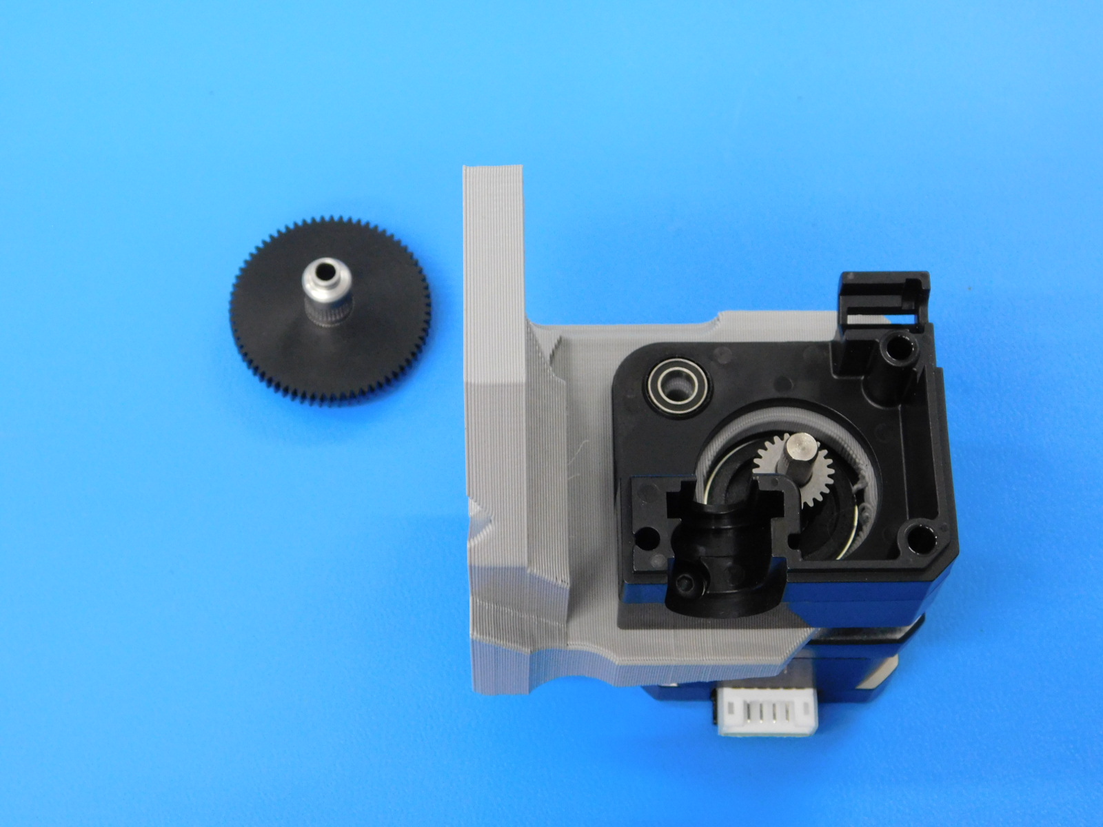
Install one sealed MR95ZZ bearing [HD-MS0446] into the extruder body [PP-MP0204] as shown.
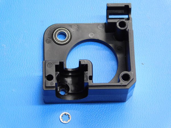
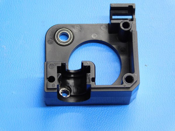
Install the internal lock washer [HD-WA0027] as shown.
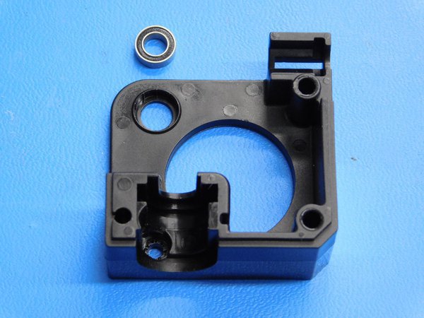
Using one M3 x 12 BHCS [HD-BT0146], fasten the extruder body [PP-MP0204] to the motor through the printed mount [PP-IS0070].
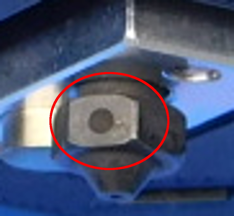
To verify the correct E3D Volcano nozzle size is being used check to make sure there are dot markings around the nozzle.
4--0.40mm
0--0.60mm
1--0.80mm
2--1.00mm
3--1.20mm
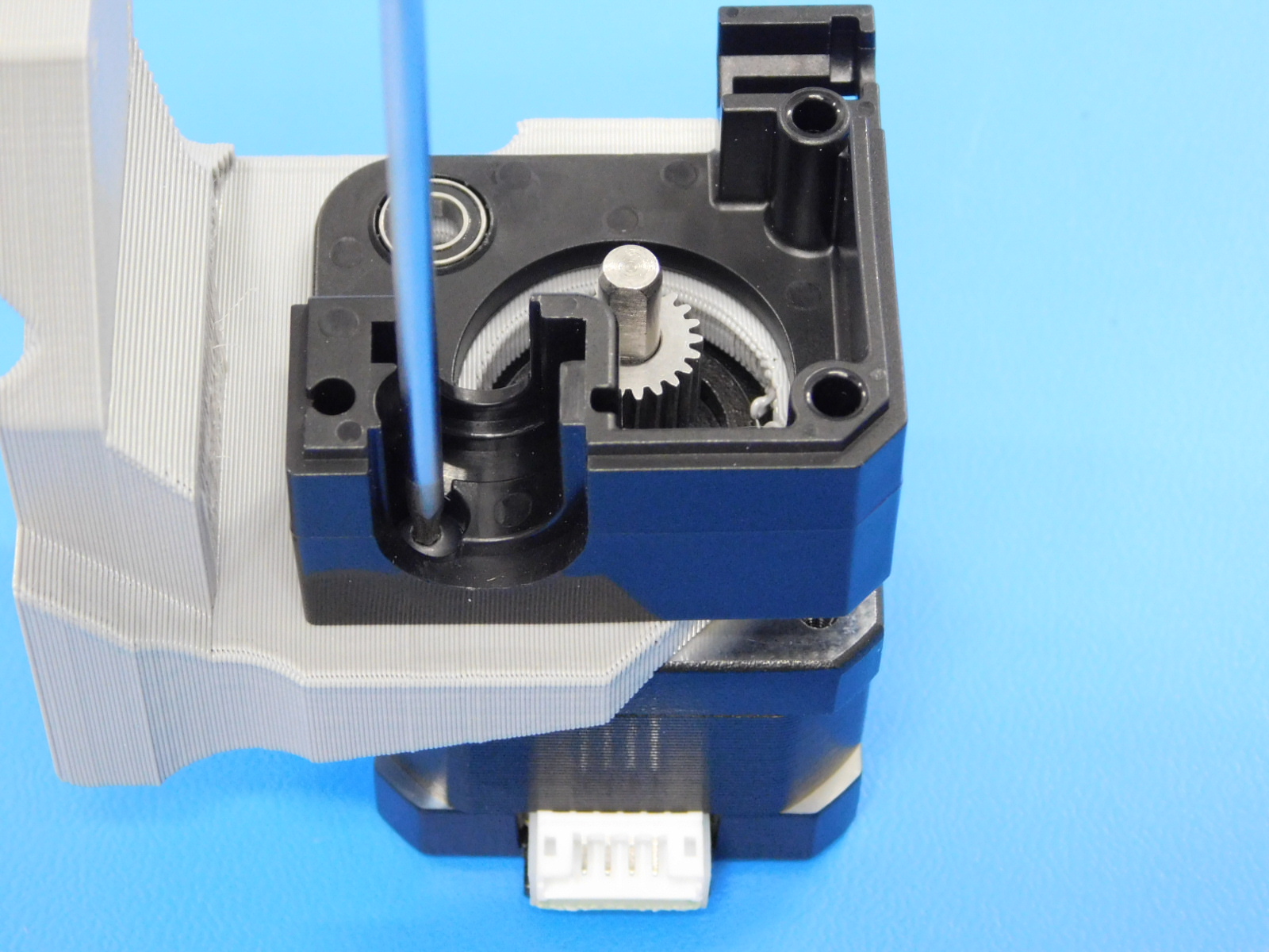
Install the bearing [HD-MS0446] into the heatsink [AS-HE0034] as shown.
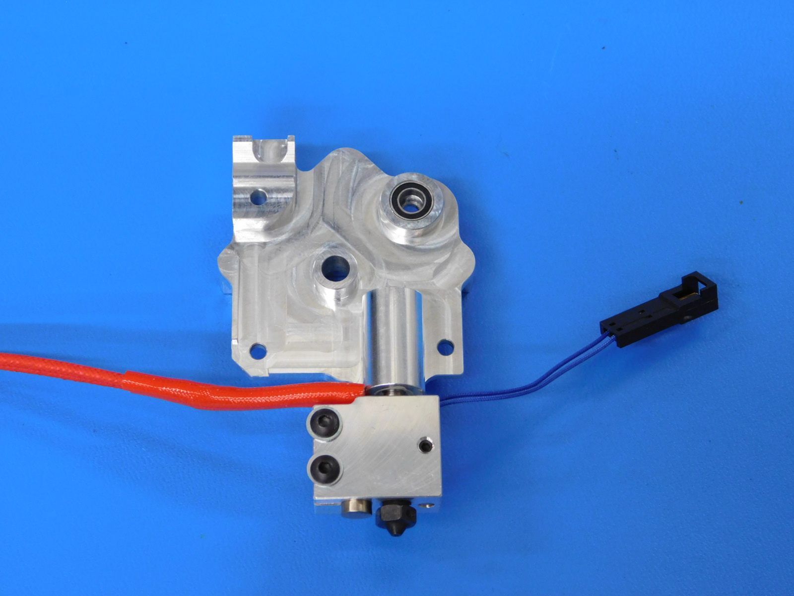
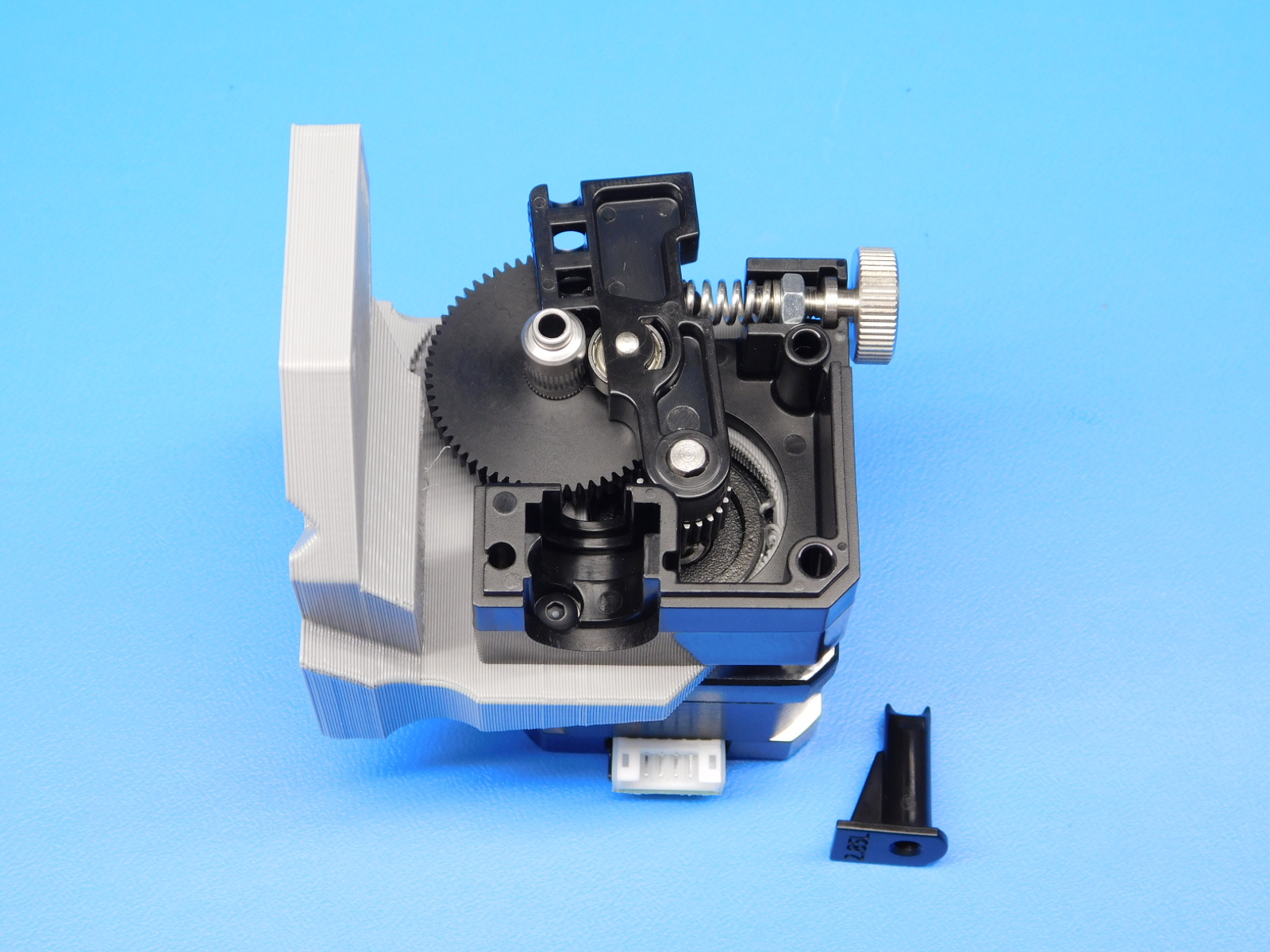
Install the large drive gear [PP-FP0154]. Make sure the faces of the two gears are flush with each other. Adjust the pinion gear as necessary. If adjustments are required, make sure to re-torque the pinon gear set screw.


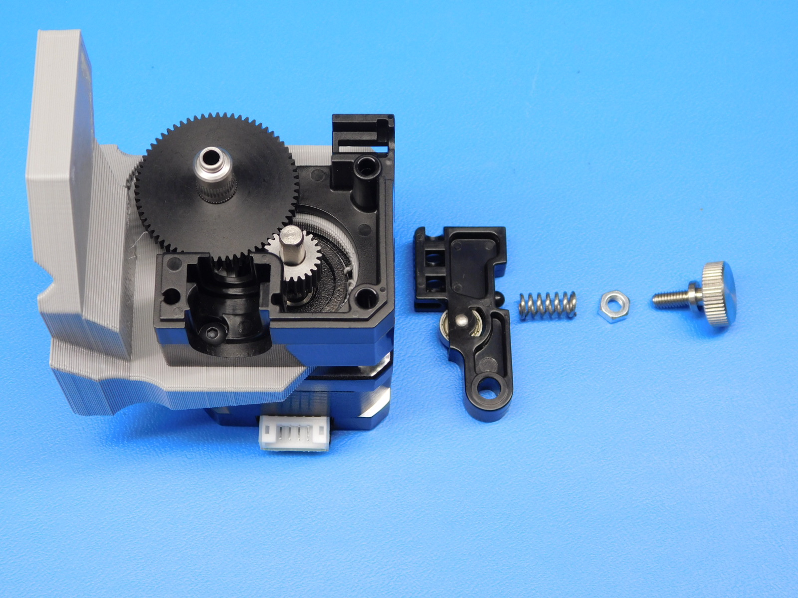
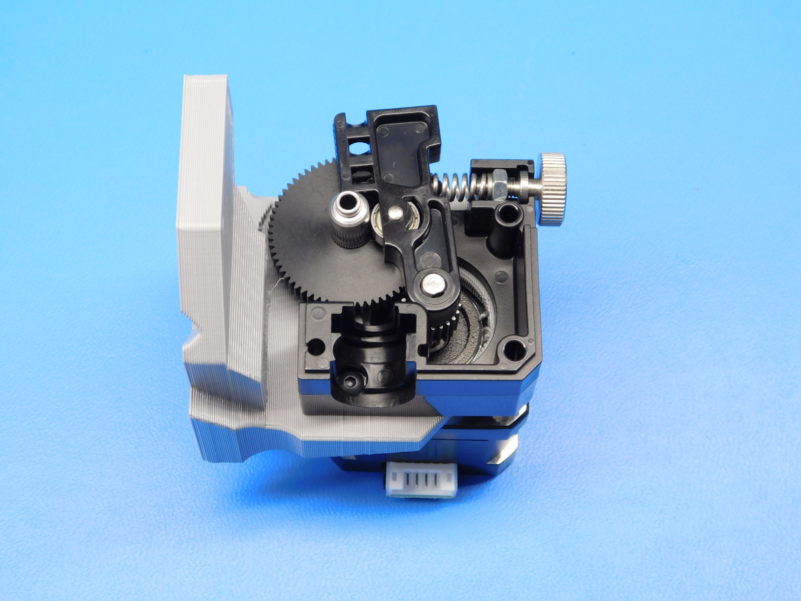
8 Install idler and spring assembly Install the idler [PP-FP0135] and the idler spring assembly [HD-NT0011], [HD-MS0430], and [HD-BT0197].
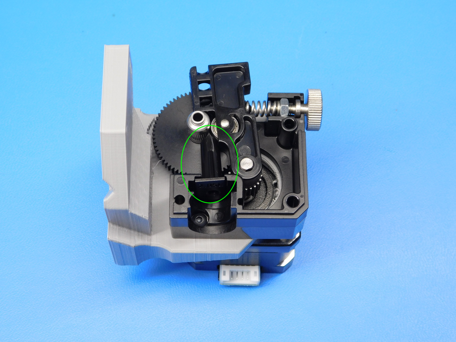
Install the filament guide path [PP-FP0136] as shown.
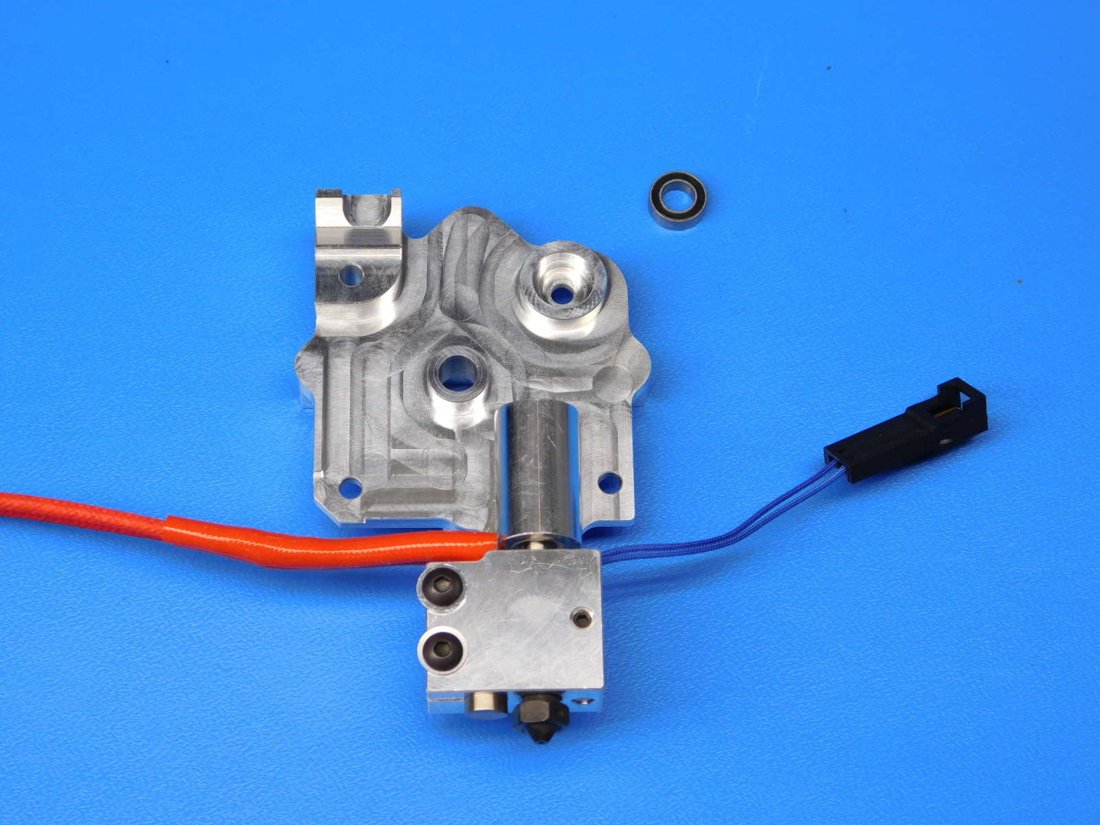
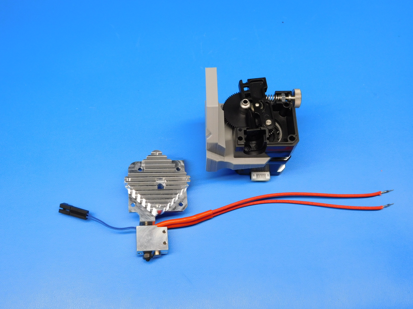
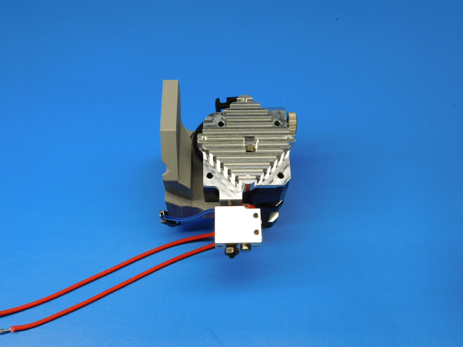
Install the heatsink assembly [AS-HE0034] onto the Extruder Body as shown.
Route the heater cartridge wires and the thermistor wires as shown.
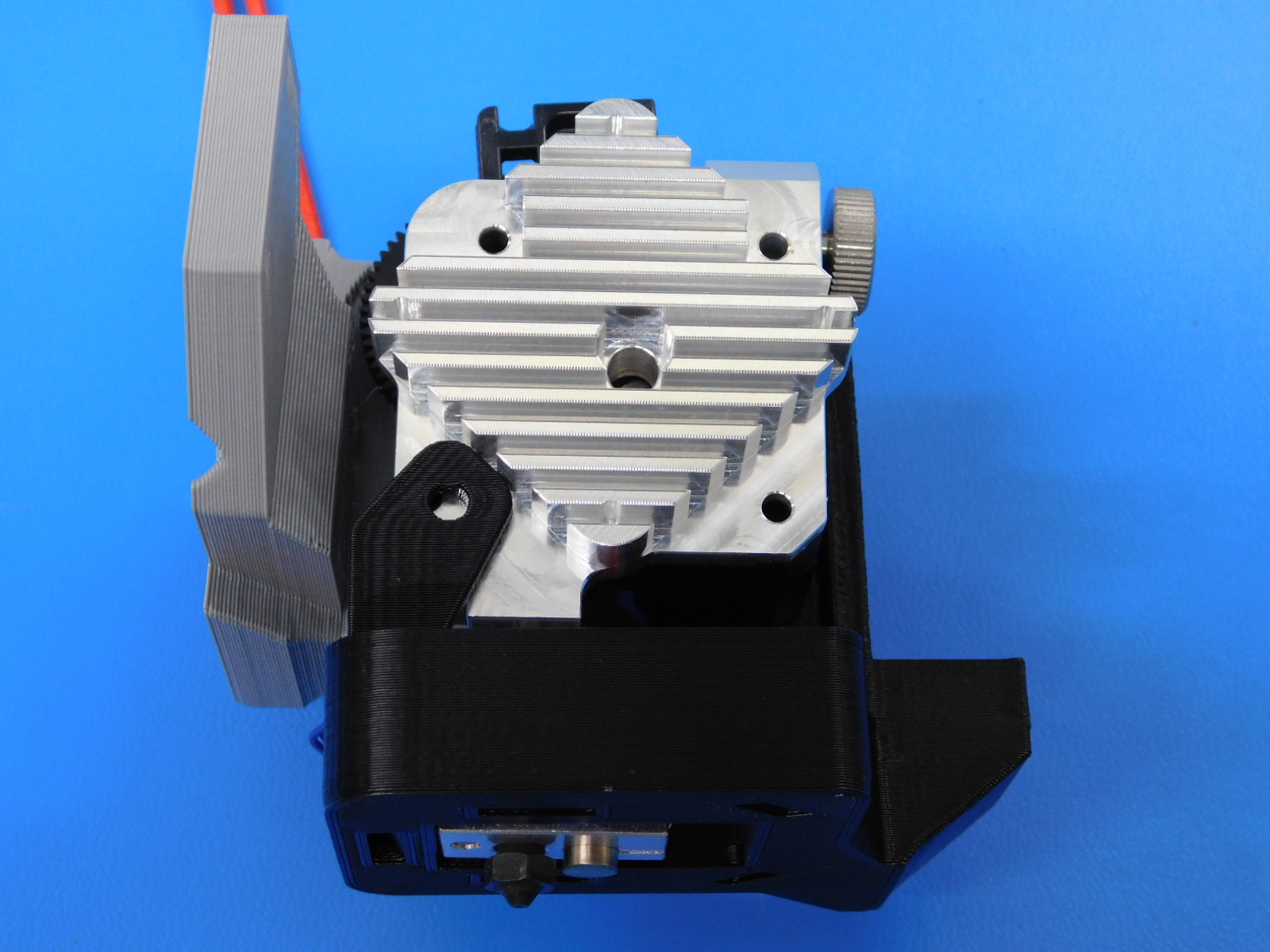
Slide the blower shroud [PP-IS0069] over the hotend.
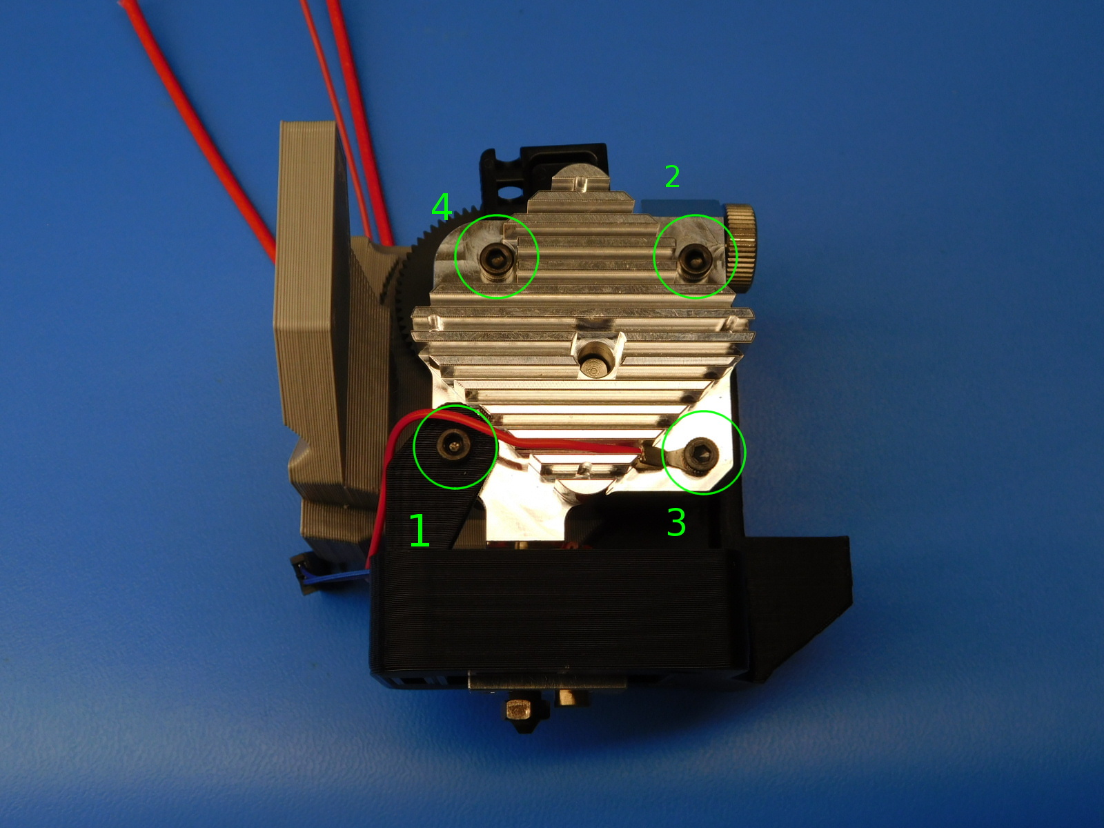
Put the zero sense line [AS-CB0063] onto one of the M3x35 SHCS [HD-BT0043], then put it into the lower right mounting hole as shown.
Put in the other two M3x35 SHCS [HD-BT0043] into the top two mounting holes, and put the M3x30 SHCS [HD-BT0042] into the lower left mounting hole.
Make sure not to pinch the zero sense line.
Torque the fasteners to 3 in * lbs in the sequence shown in the photo.
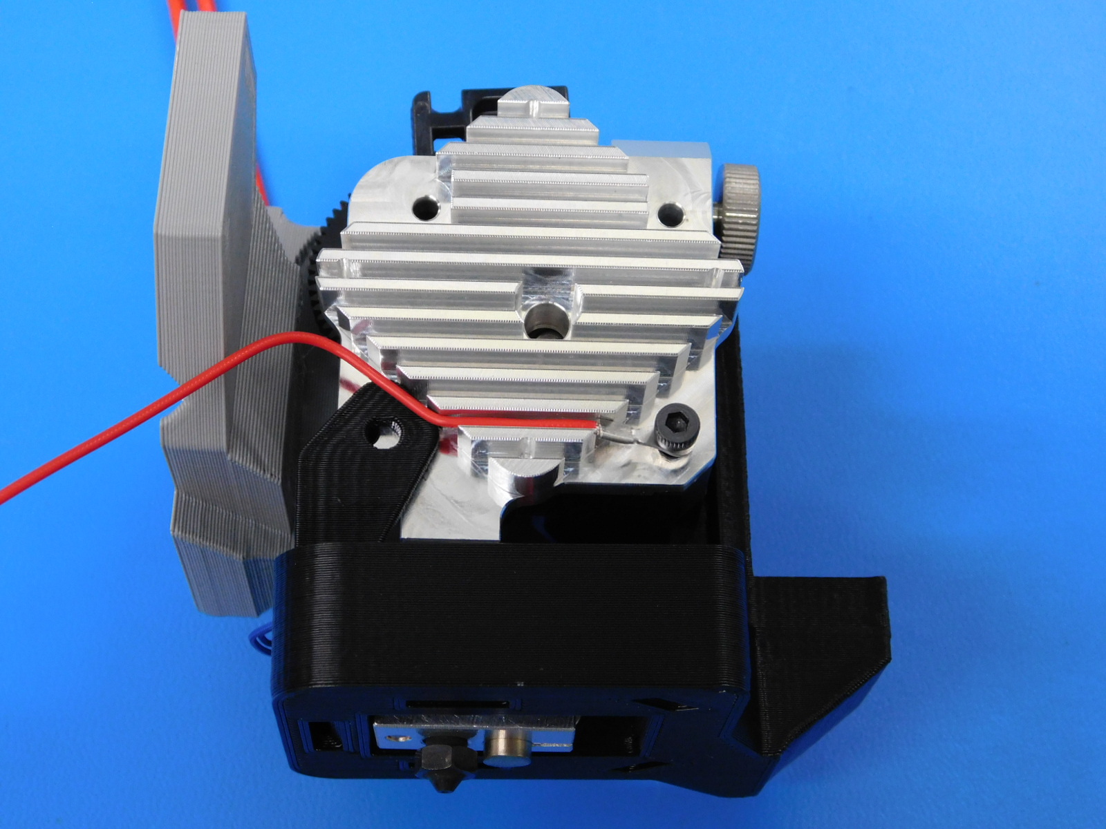
Route the Hotend Ground wire as pictured.
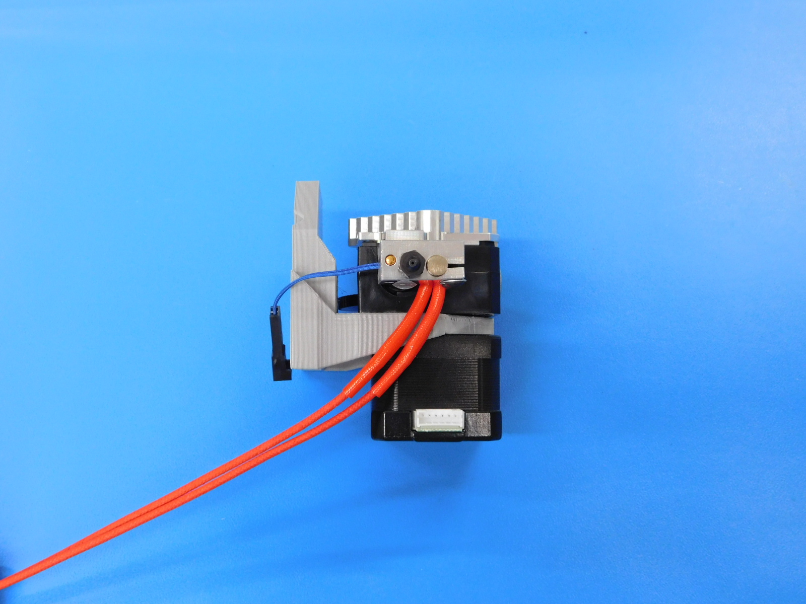
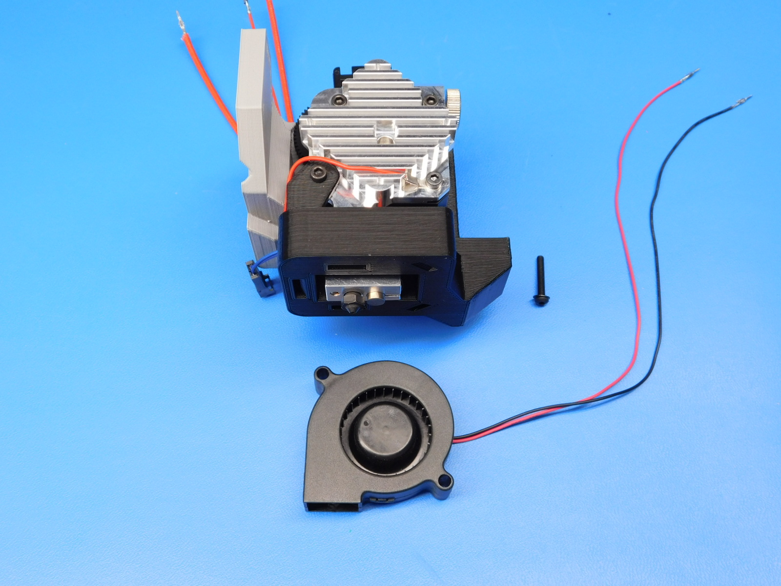
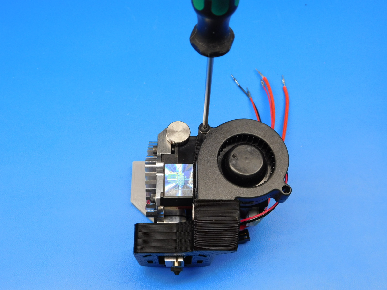
Using one M3 x 20 BHCS [HD-BT0171] with a washer [HD-WA0038], install the blower fan [AS-CB0062] as shown.
Route the wires around back by the motor connector.
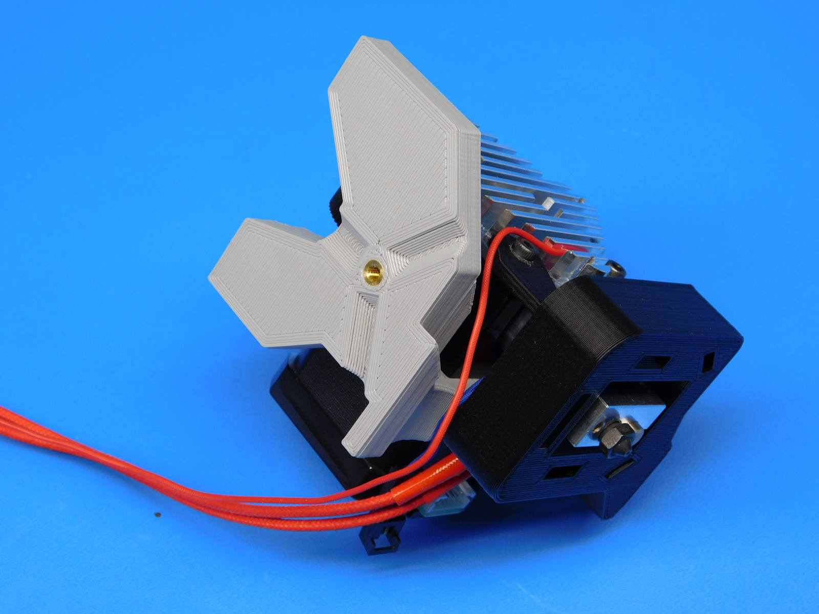
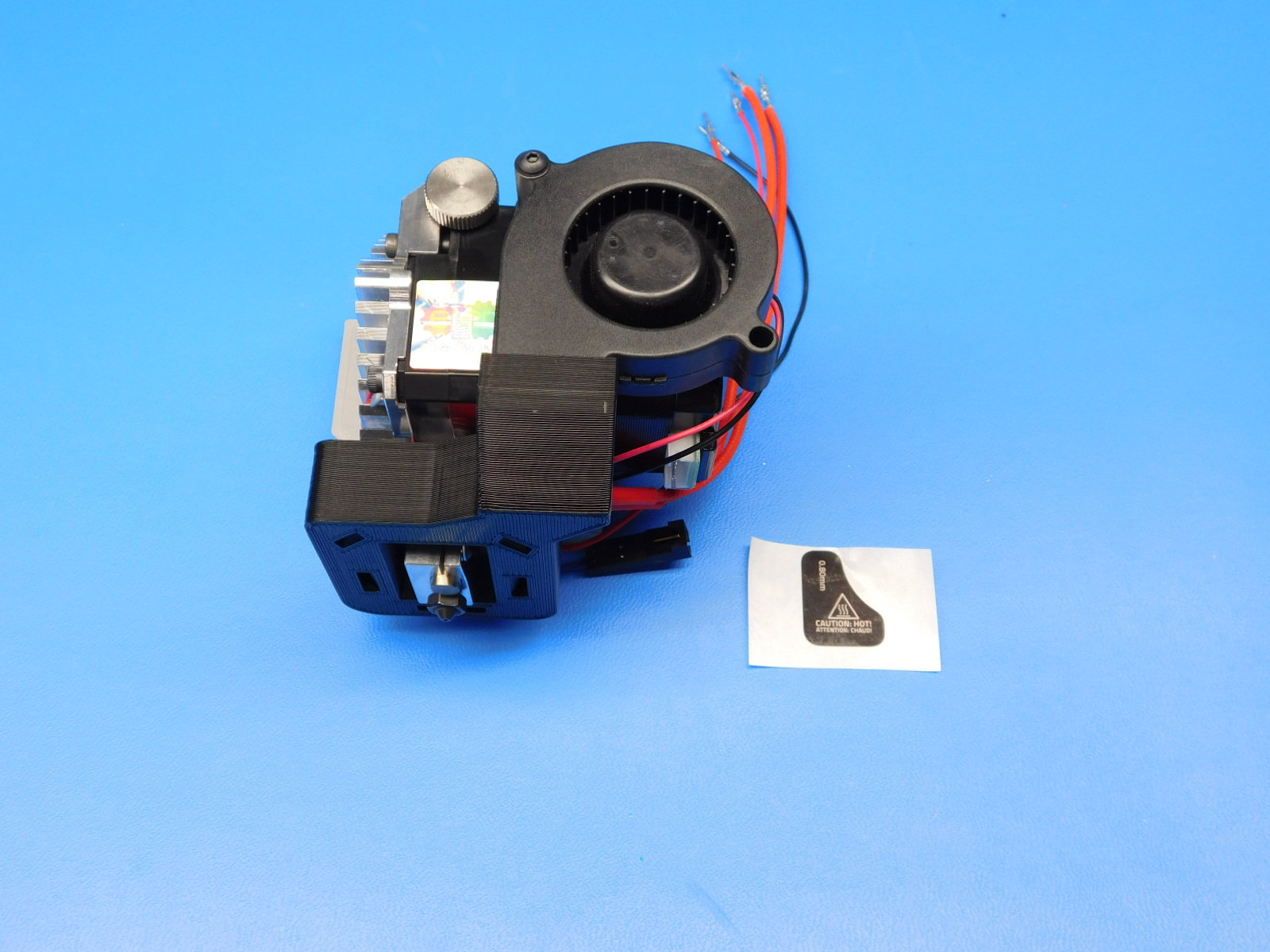
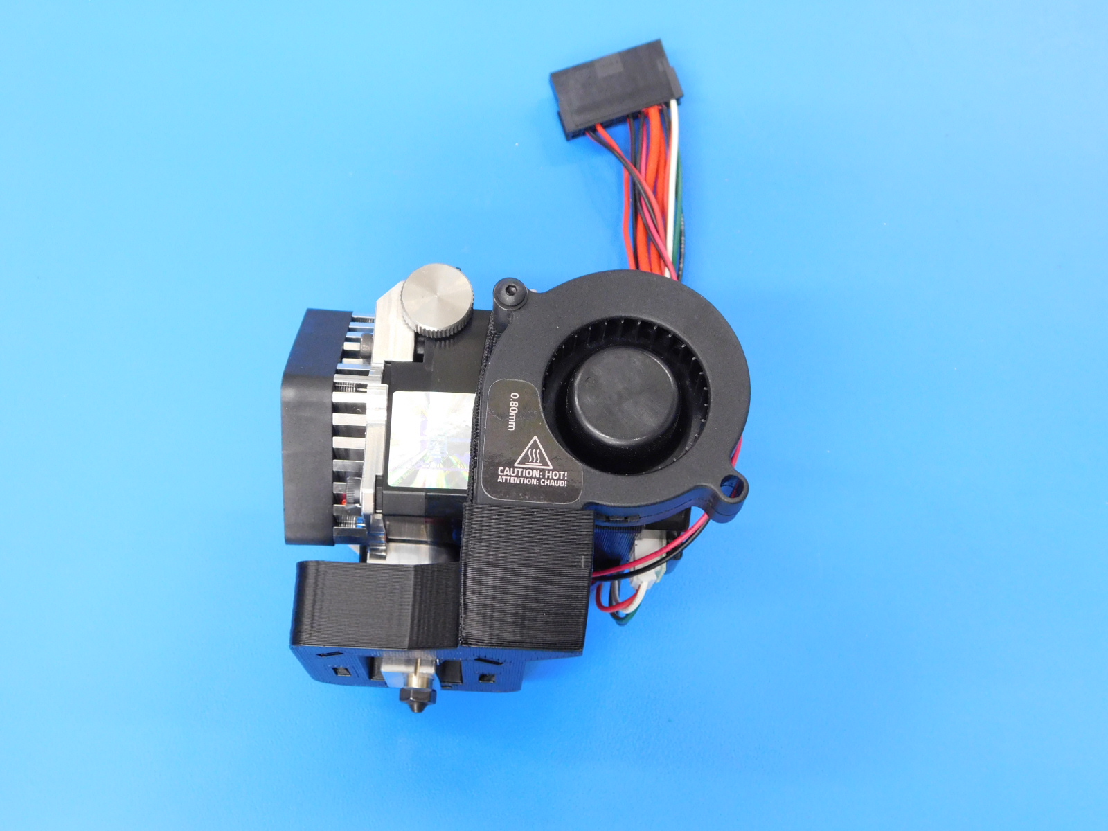
Apply 1x- 0.80mm "Hot" Warning Sticker [DC-LB0167] to the part cooling fan, exactly as pictured.
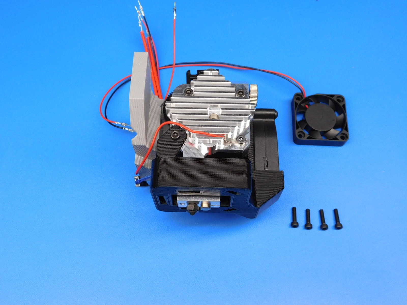
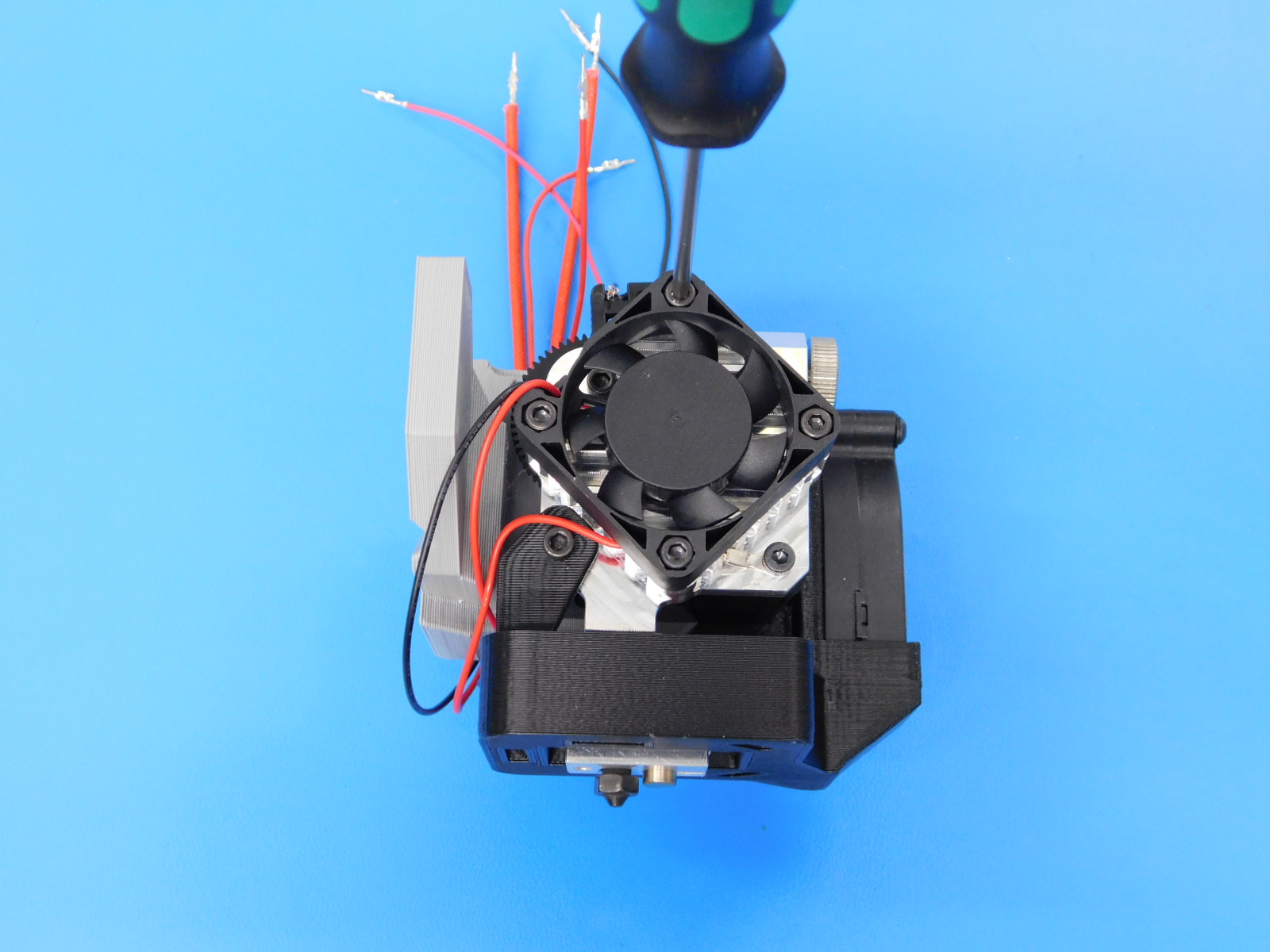
Using four M3 x 12 SHCS [HD-BT0039]. install heatsink fan [AS-CB0064] as shown.
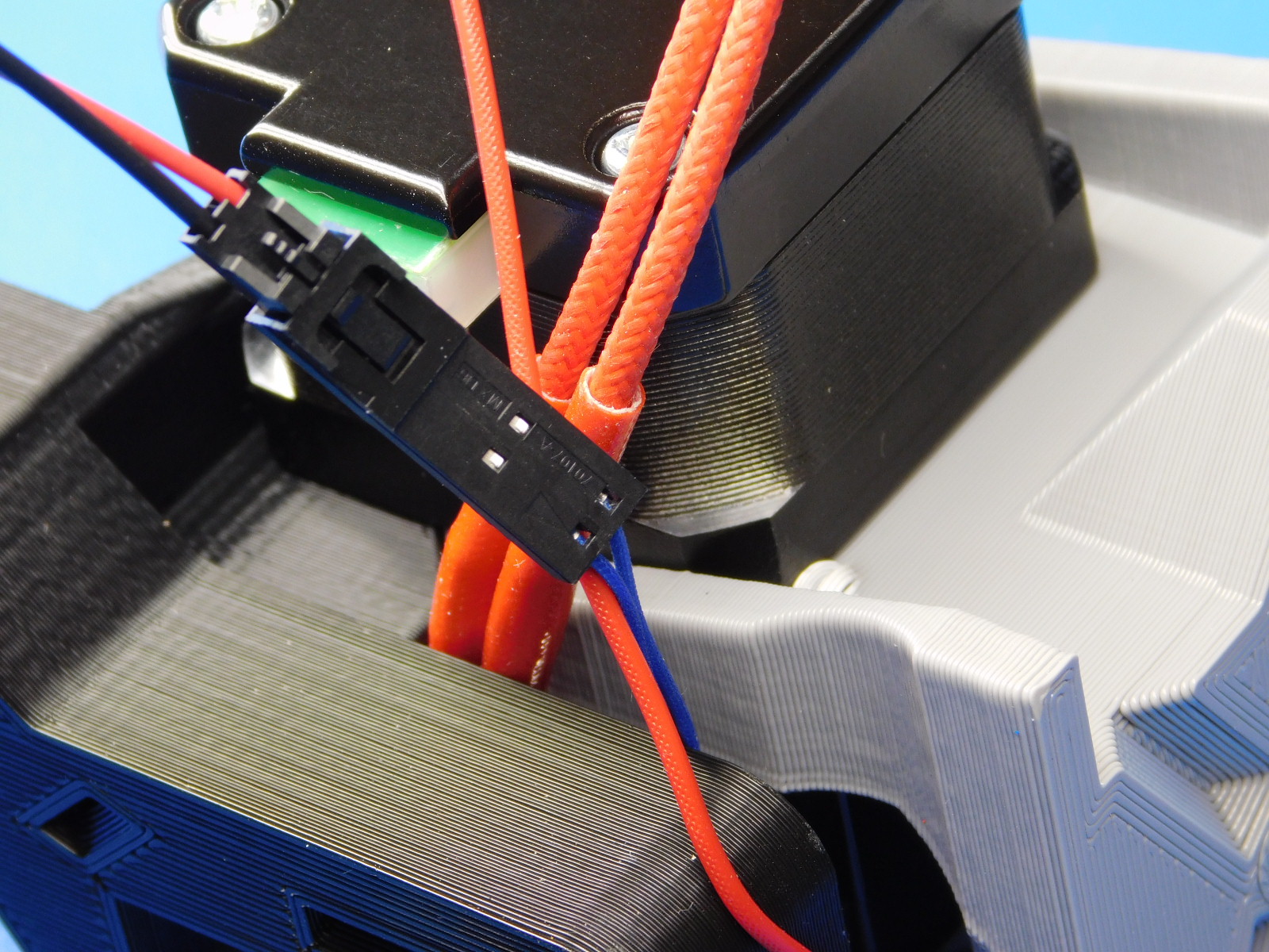
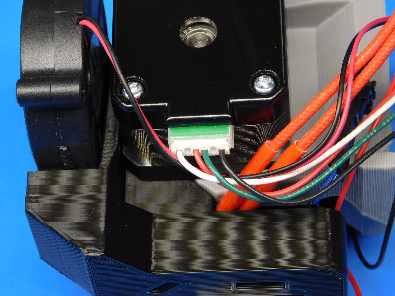
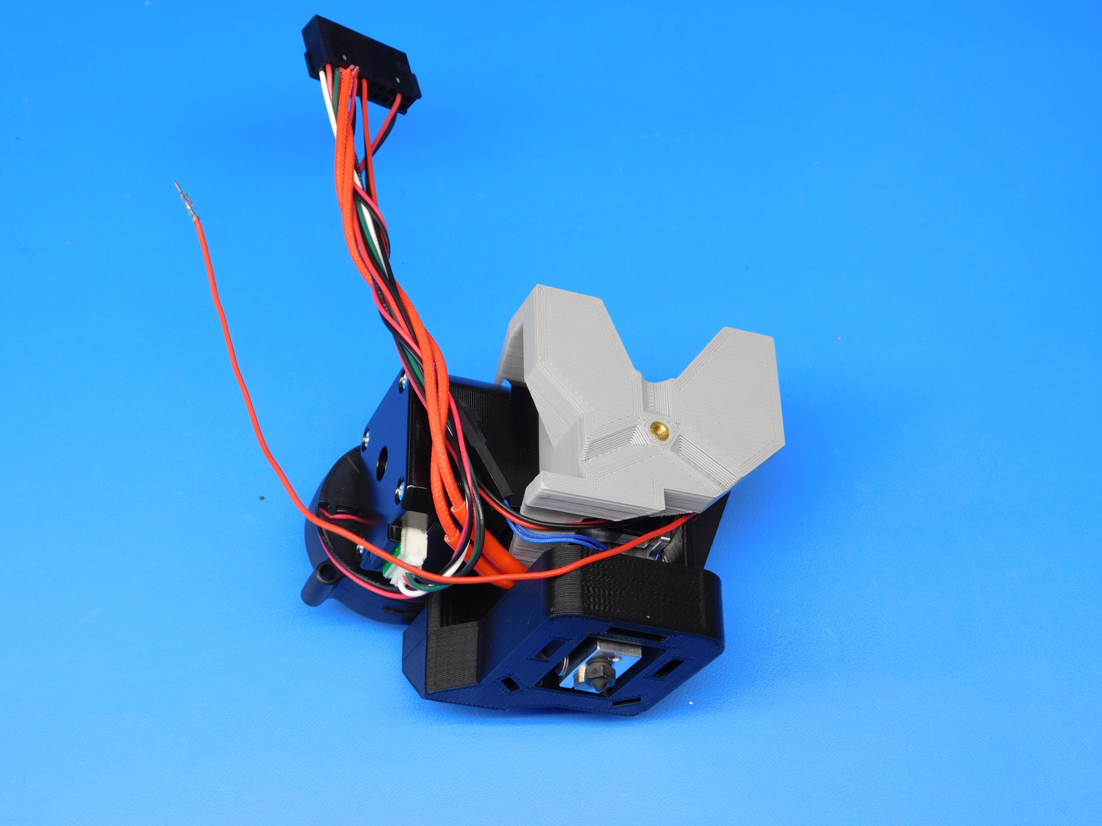
Connect motor harness [AS-CB0061] and thermistor extension harness [AS-CB0066] as pictured
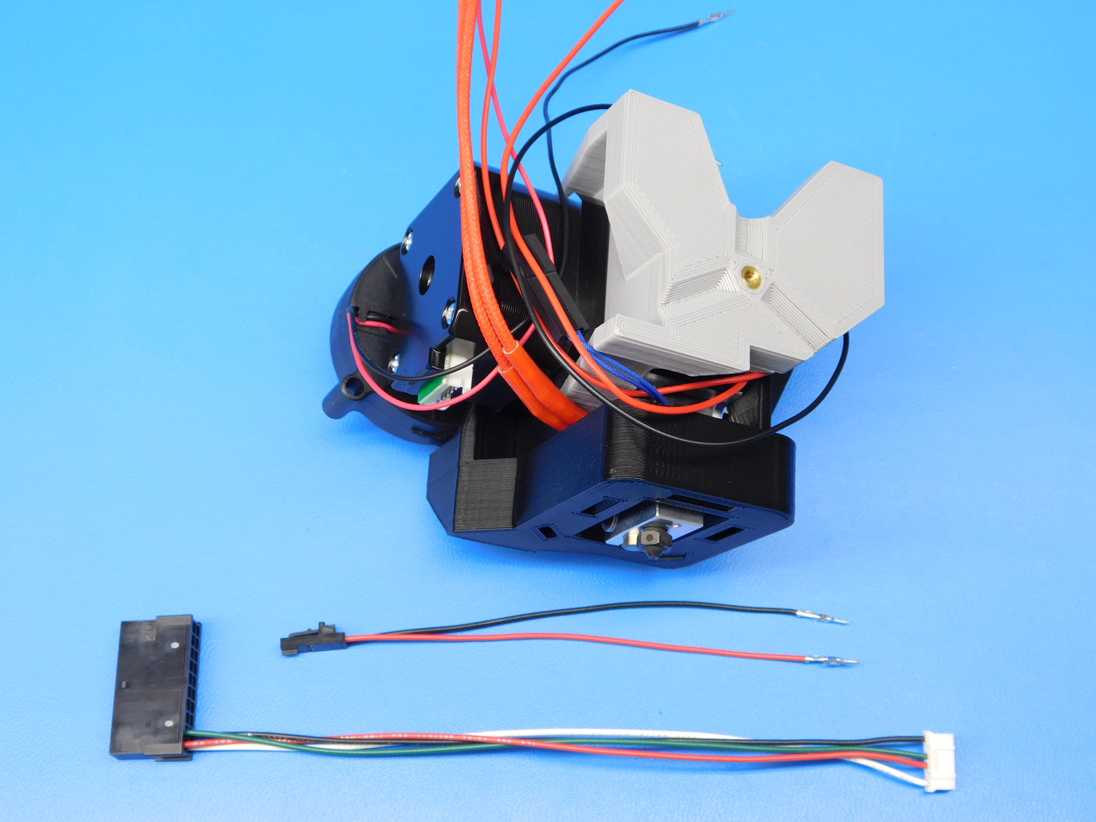
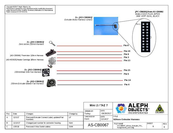
Pin all harnesses to the connector according to the diagram, excluding the hotend ground wire until the next step.

While pinning the hotend ground wire last, wrap around the bundle of wires once or twice as pictured before pinning.
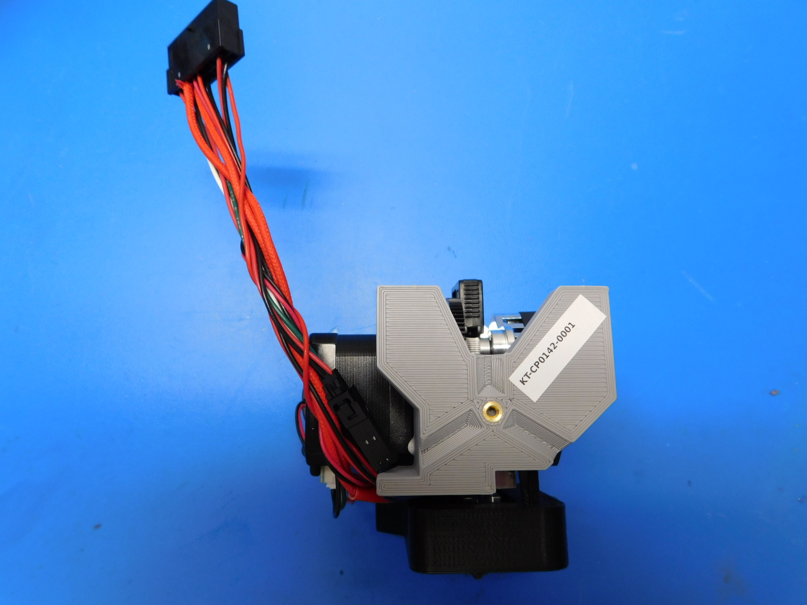
After the ground pin is set. Place a label on the back of the extruder mount [PP-IS0070] to the right side at a 60 degree angle as shown.
After assembly of the Lulzbot HS tool Head is complete, it is necessary to verify the electrical properties of the toolhead, namely the heater cartridge and thermistor.
Refer to the pin-out diagram above for pin locations
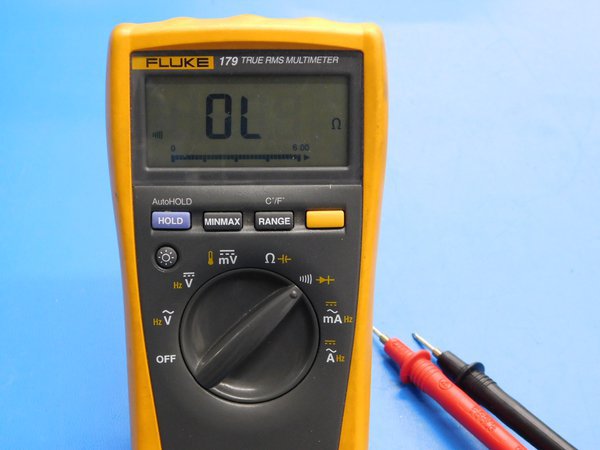
First we will test the resistance value of the heater cartridge; To do so, first set your multimeter to Ohms which is signified by the capital Greek letter Omega. Now touch the probes of your multimeter to pins 3 & 13 individually. Note: Positive or negative probe positions are irrelevant to this test. The display on the multimeter should now show a value around 19 Ohms. Any value between 12.8 and 14.4 Ohms is acceptable, values outside of that range are cause for rejection of the heater cartridge and it should be replaced.
Next we will verify that the heater cartridge DOES NOT have continuity to the ground circuit. To do so, the multimeter may remain in Ohms mode or be switched to an audible continuity test mode by moving the switch to the symbol representing sound waves. Now touch one probe to the heater block, and the other to pins 3 and then 13, individually. Note: Positive or negative probe positions are irrelevant to this test. Whether probing pin 3 or 13, the multimeter display should remain at 0 and no audible alarm should sound. This indicates that there is no continuity between either lead of the heater cartridge and the toolheads ground circuit. If the multimeter display reads anything but 0, or an audible alarm is heard during either half of this test, the heater cartridge must be rejected and replaced.
Next we will perform the same tests for the thermistor. To do so, first set your multimeter to Ohms which is signified by the capital Greek letter Omega. Now touch the probes of your multimeter to pins 9 & 19 individually. Note: Positive or negative probe positions are irrelevant to this test. The display on the multimeter should now show a value between 80 and 120 K Ohms. Pay close attention to the units displayed on the multimeter's display; the letter 'K' should be displayed to the right of the value. If a reading is given in Ohms or Mega Ohms (indicated by the letter 'M' to the right of the value displayed) or the kOhms reading is too low (values displayed as 1.xx or similar) or otherwise outside of the range stated above, the thermistor must be rejected and replaced.
Next we will verify that the thermistor DOES NOT have continuity to the ground circuit. To do so, the multimeter may remain in Ohms mode or be switched to an audible continuity test mode by moving the switch to the symbol representing sound waves. Now touch one probe to the heater block, and the other to pins 9 and then 19, individually. Note: Positive or negative probe positions are irrelevant to this test. Whether probing pin 9 or 19, the multimeter display should remain at 0 and no audible alarm should sound. This indicates that there is no continuity between either lead of the thermistor and the toolhead's ground circuit. If the multimeter display reads anything but 0, or an audible alarm is heard during either half of this test, the thermistor must be rejected and replaced.
To finalize this test, verify that the zero sense line (ground circuit) has continuity to the nozzle. This test is best performed in the audible continuity mode. Touch one probe to the nozzle or heater block, and the other to pin 8 on the toolhead's connector. Note: Positive or negative probe positions are irrelevant to this test. An audible alarm should sound indicating that continuity is present. If so, the toolhead has passed electrical testing and may proceed to final extrusion testing. Congratulations!

Put the toolhead onto the test stand and run the test gcode. Make sure:
1) The heatsink fan is on anytime the tool's controller is powered on
2) That the blower fan runs without being too noisy or jittery
3) That the Hotend heats up in a controlled way
4) The stepper motor moves without skipping
Visually verify the extrusion and make sure there is no debris.
Remove the remaining filament from the tool head. Once the tool head is cool, insert a cold piece of filament into the tool head and trim it to approximately 30mm of filament.
1x- [AS-PK0010] 90 mm wiper pad set
1x- [AS-TH0070] Titan Aero Assembly, HS 0.8
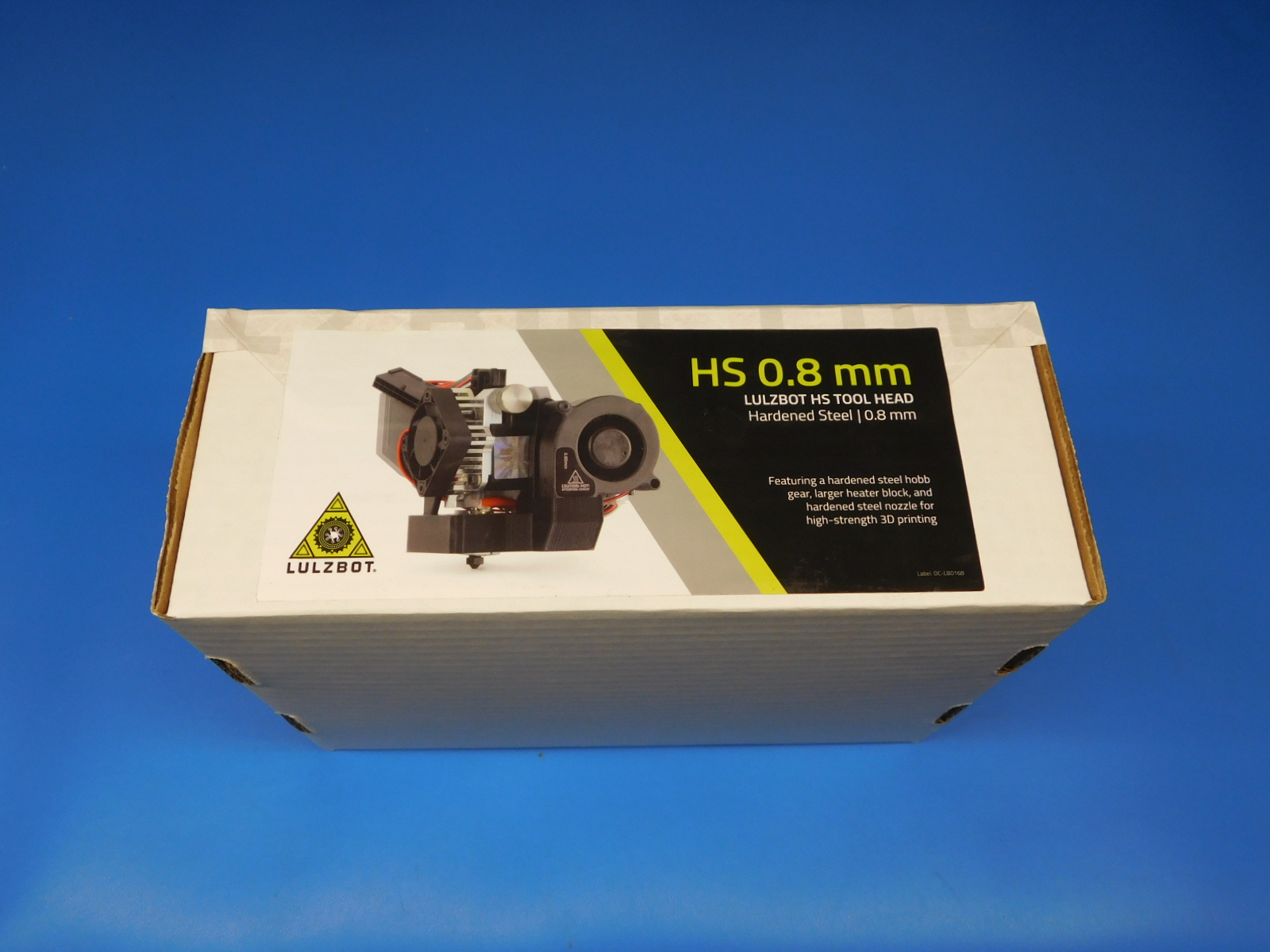
1x- [DC-LB0168] HS 0.8 Tool Head Label, Front
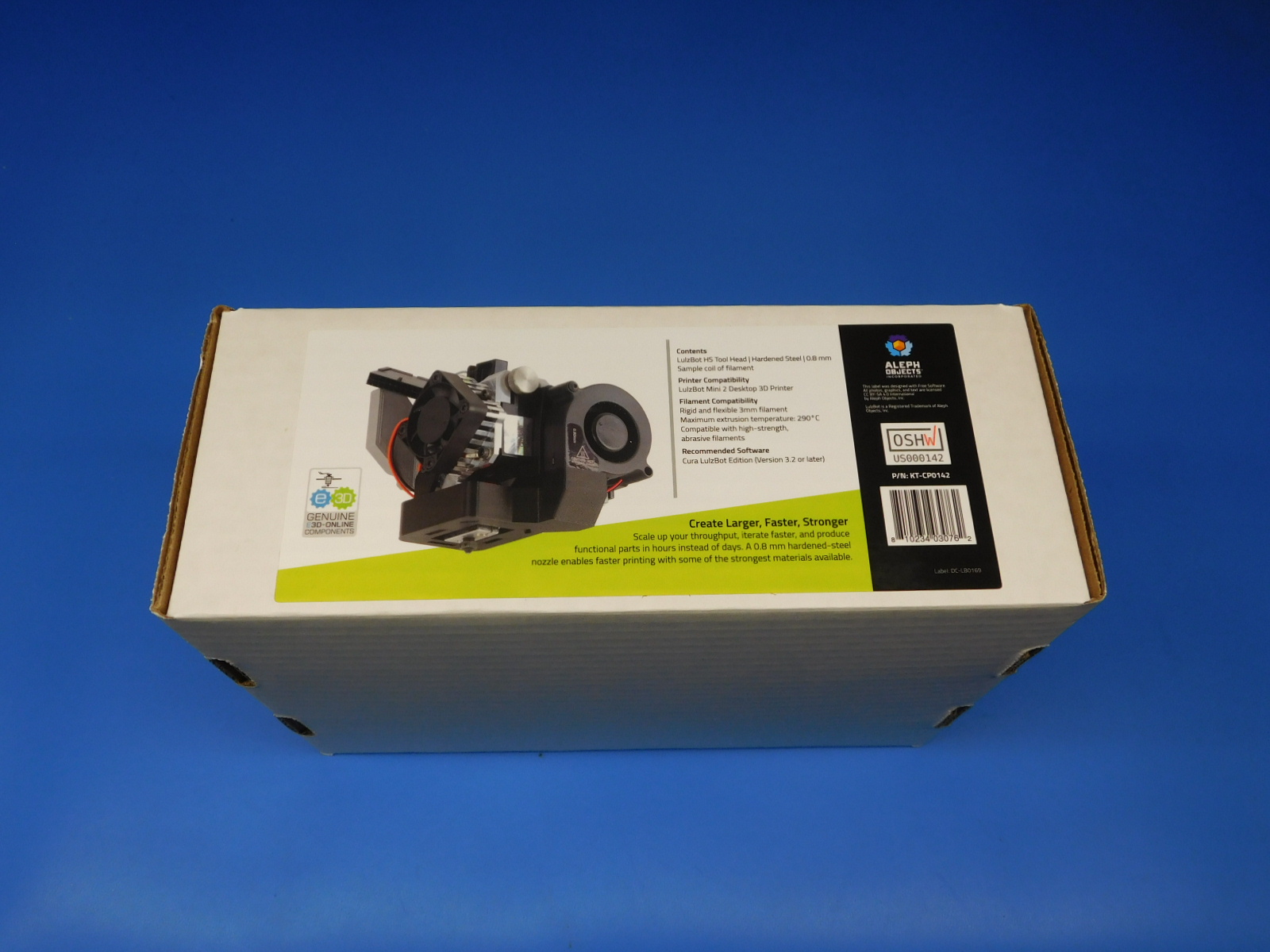
1x- [DC-LB0169] HS 0.8 Tool Head Label, Back
1x- [DC-MS0037] Colorado Made Green Sticker
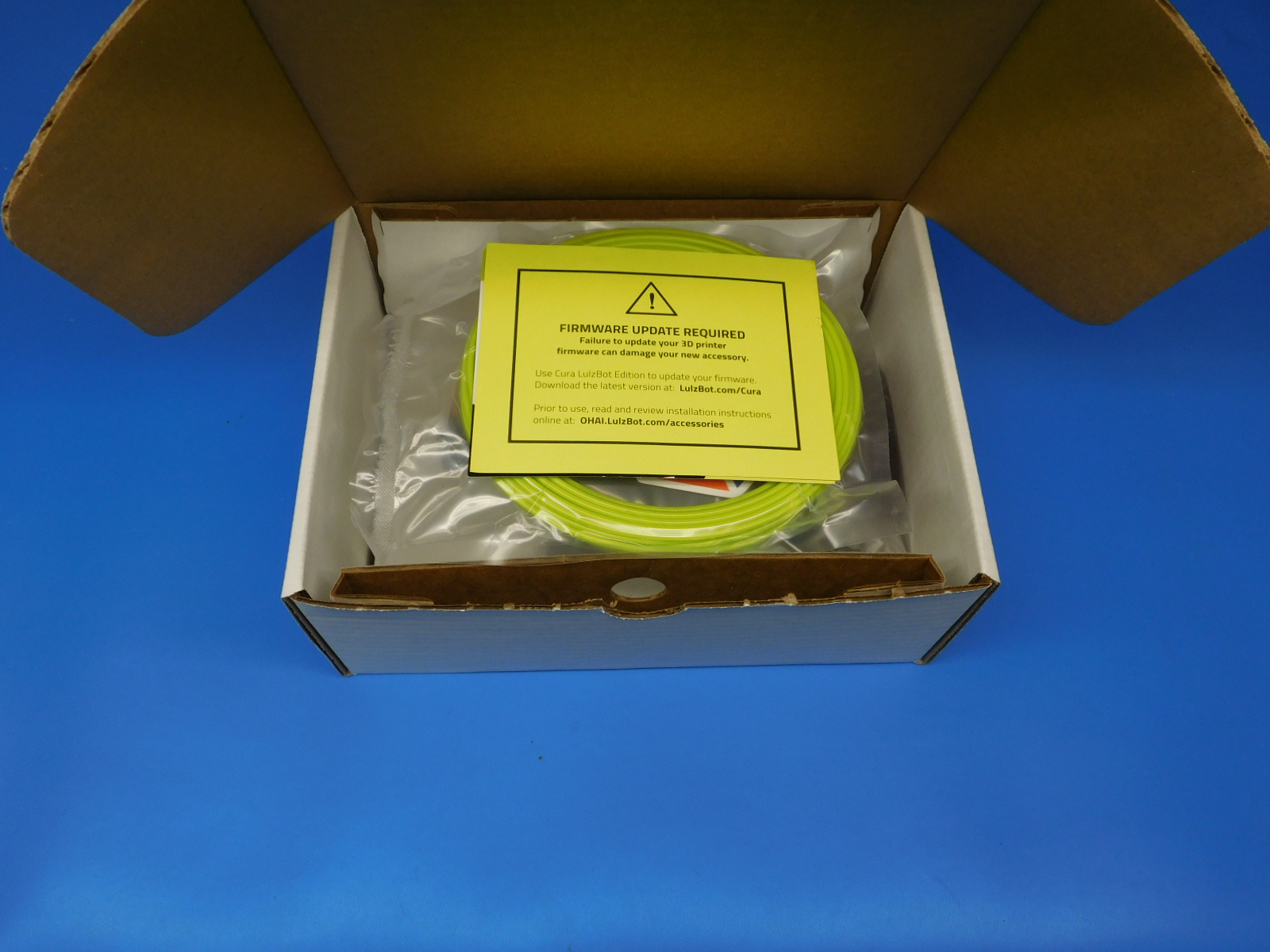
1x- [DC-MS0054] Firmware Update Warning Cards
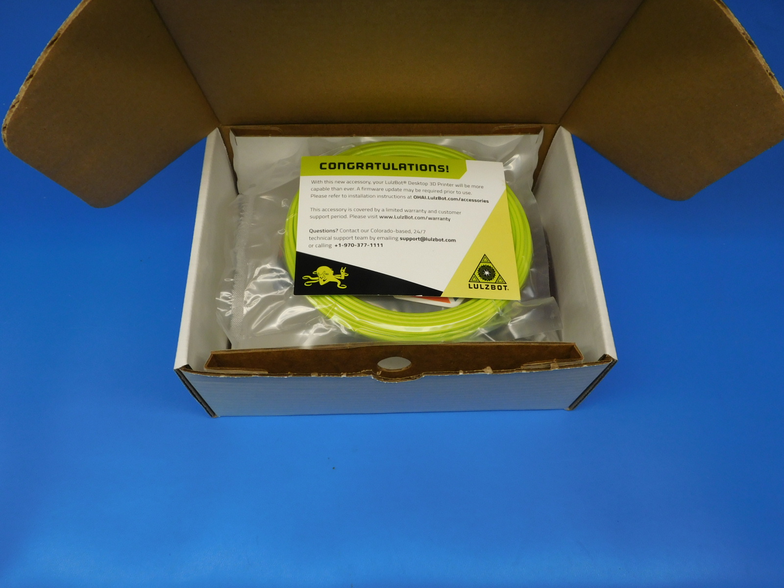
1x- [DC-MS0060] CONGRATULATIONS!- Accessory Instruction Card
1x- [PP-GP0398] HS/HS+ Double Wiper Pad Mount
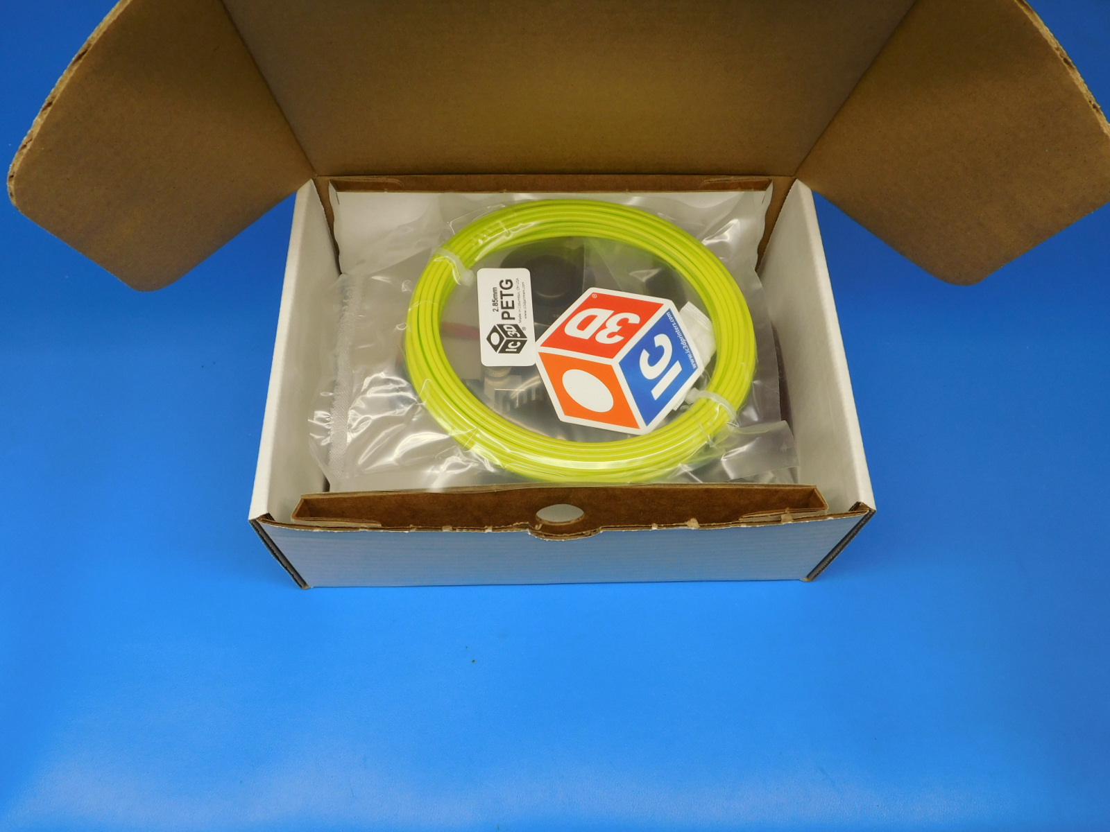
1x- [RM-PE0015] IC3D PETg Sample Pack, 65g
1x- [SH-BX0088] Accessory Tool Head Box: 9-1/2 x 7 x 3-7/8 Die Cut, 32 ECT, B Flute, Kraft, White
1x- [SH-PA0049] Korrvu Medium Retention Pack for Standard Tool Heads
1x- [SH-PG0025] 5 x 8" 2 Mil Reclosable Bag
1x- [SH-PG0131] #260 White Reinforced Gummed Tape with LulzBot Printed Logo
1x- [TL-CS0255] Scotch Brite Maroon Pad, 2"X 3"
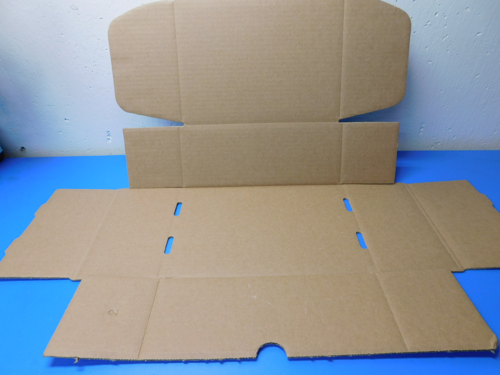
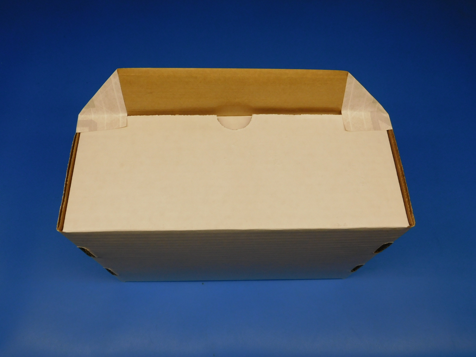
Take your unfolded box [SH-BX0088] placing so that the fold creases are facing you and start by folding up the flaps on the left side of the box as shown.
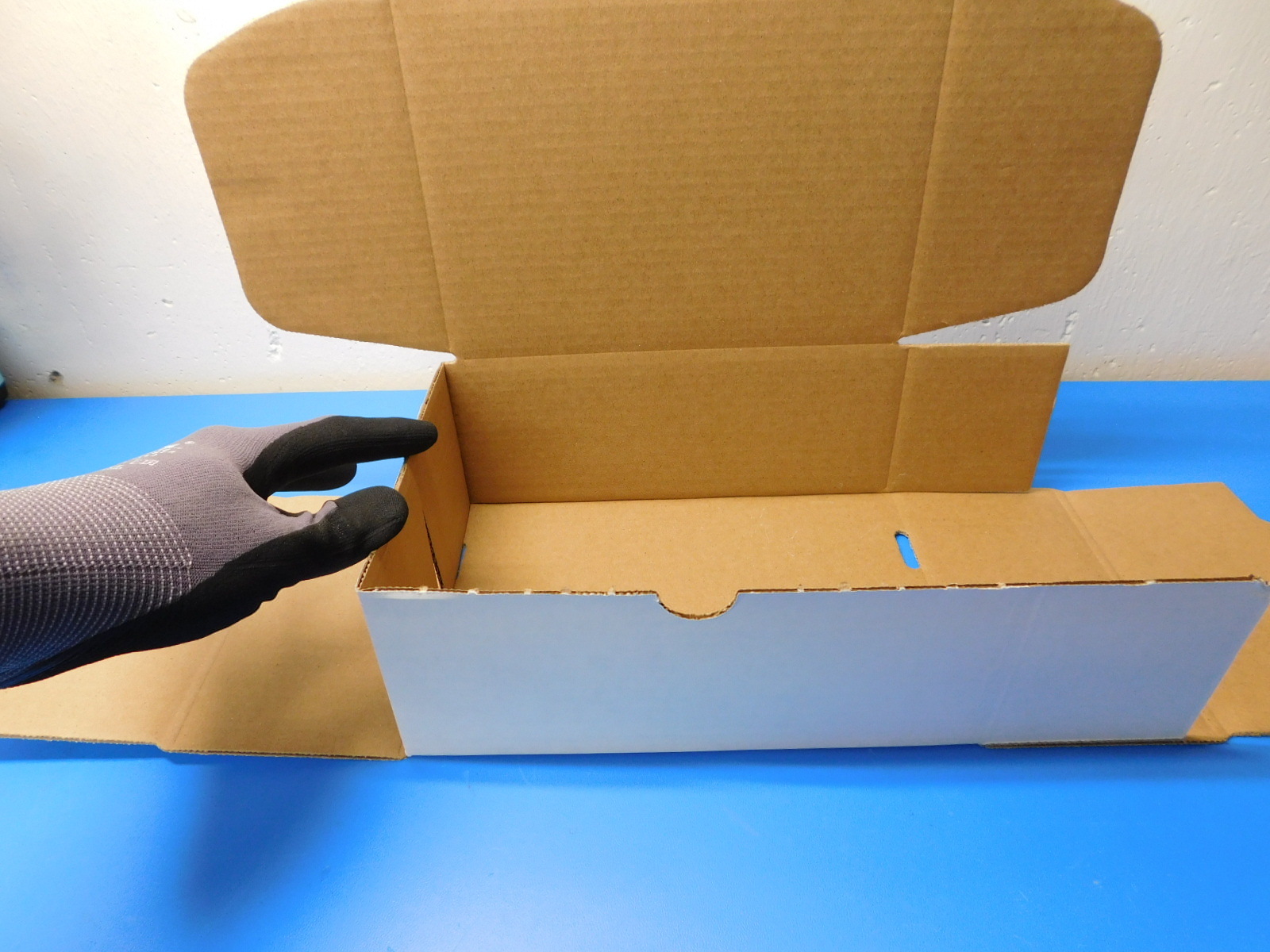
Next fold those side in towards the middle, as shown.
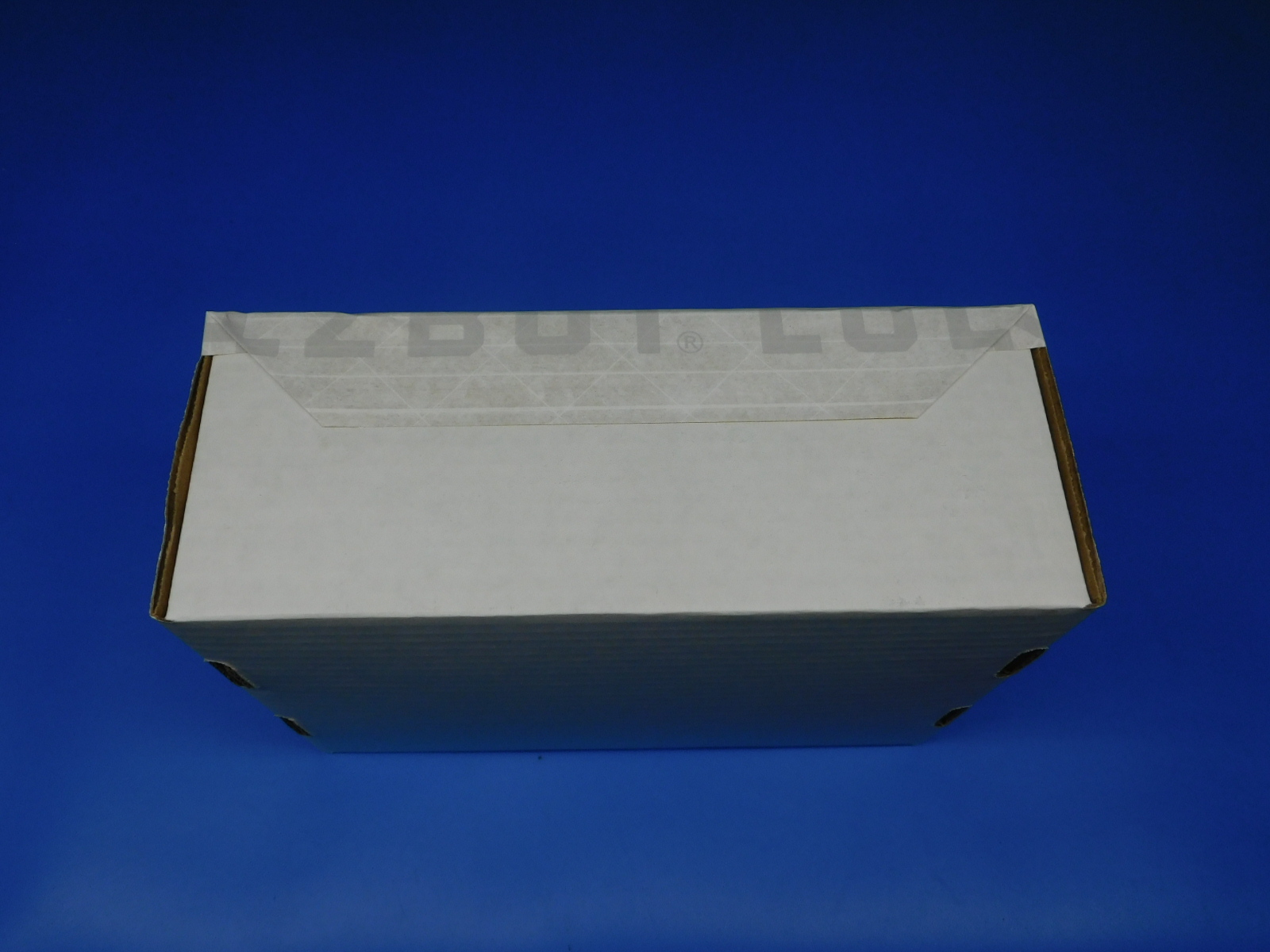
Now take the longer flap and fold it over the two side flaps we brought in towards the middle, as shown.
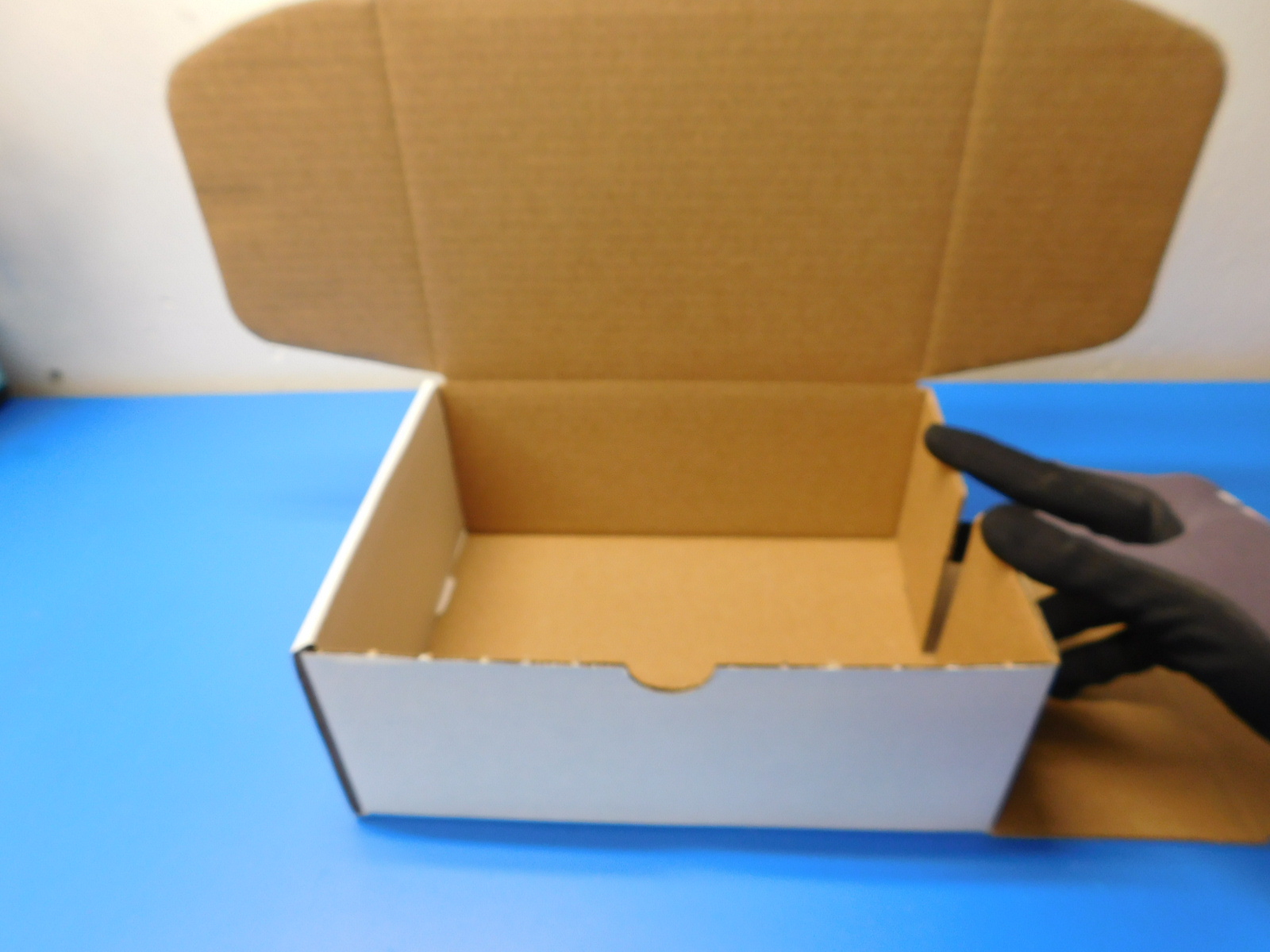
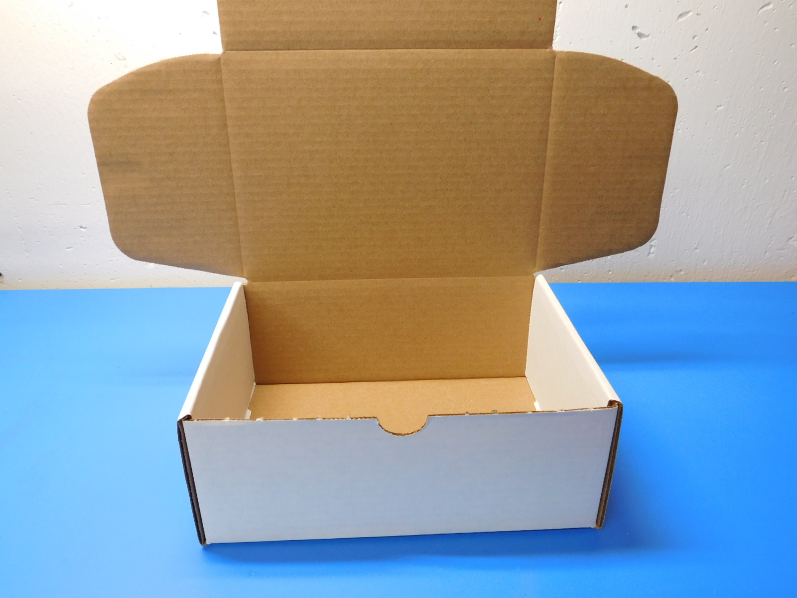
Repeat this process for the right side flaps.
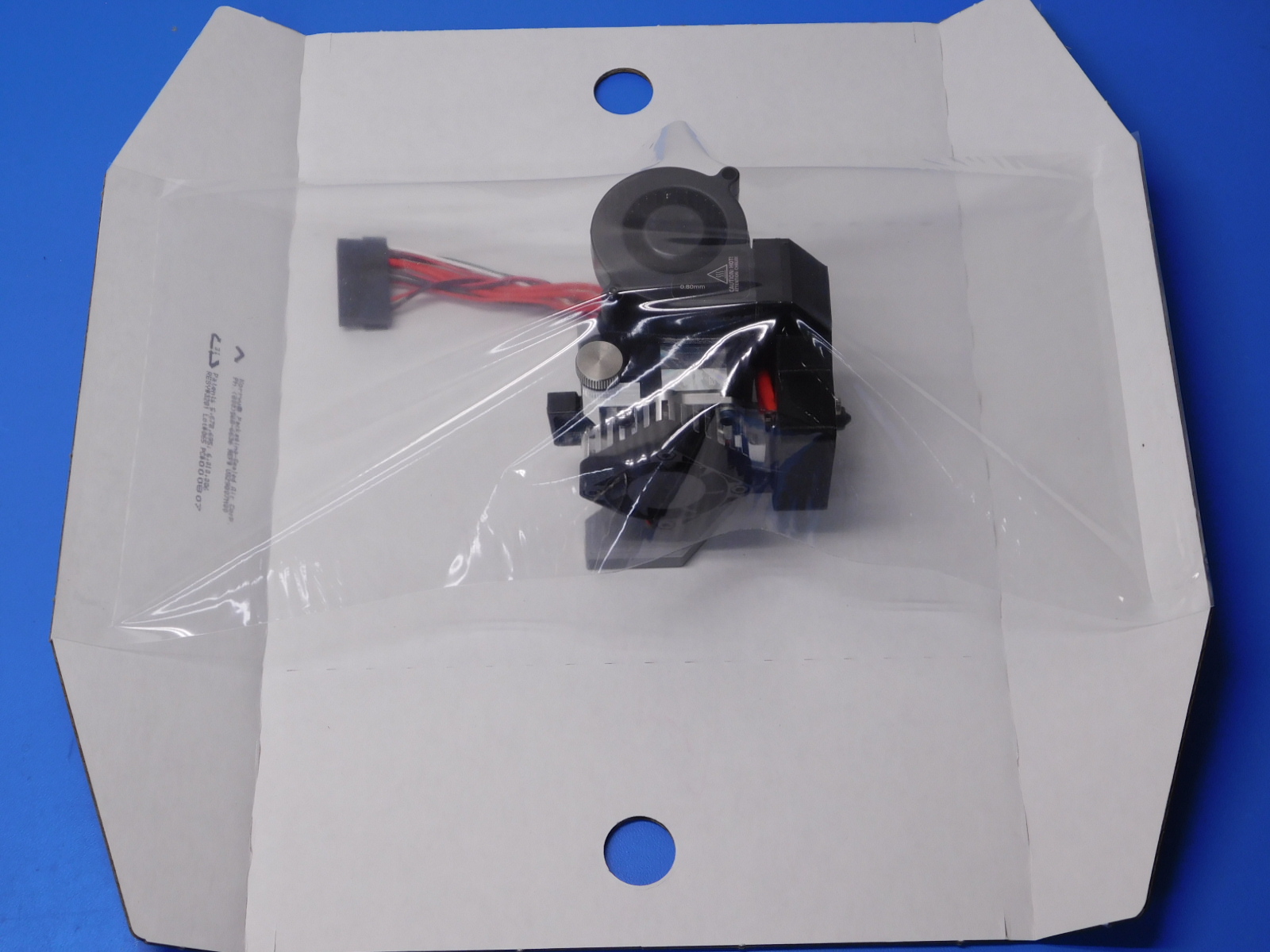
We will now place the Aerostruder tool head into the Korrvu [SH-PA0049].
First take the Korrvu and fold up the flaps without the finger holes. This will loosen the plastic wrap so we can slide the tool head under it.
Now slide the tool head under the plastic wrap. Make sure when you slide the tool head in, the tool head should be lying on the motor with the heat sink fan facing you.
Next, fold the flaps without the finger holes down. This will tighten the plastic of the Korrvu over the tool head.
Now we can fold the flaps with the finger holes up so we can place the tool head into the box.

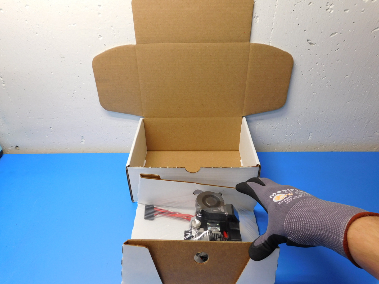
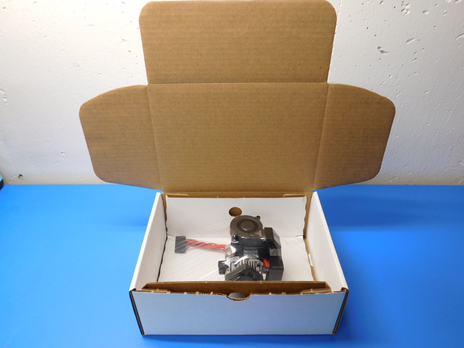
Place the tool head, inside the Korrvu and place it in the box as shown.
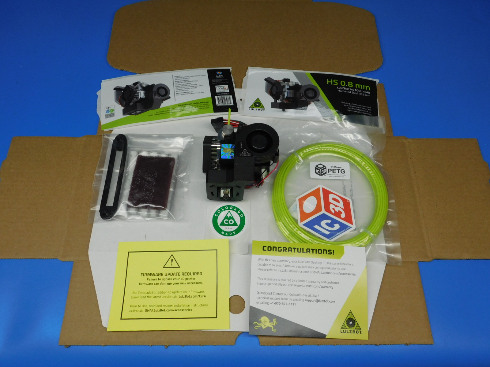
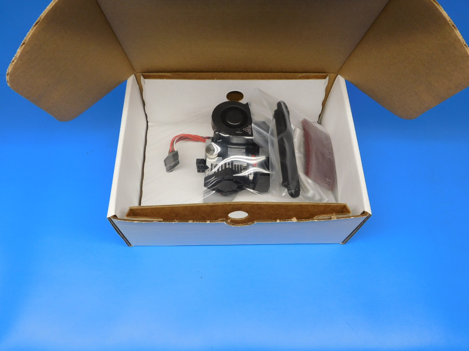
First bag [TL-CS0255] Scotch Brite Maroon Pad, [PP-GP0398] HS/HS+ Double Wiper Pad Mount, and [AS-PK0010] 90 mm wiper pad set into the [SH-PG0025] 5 x 8" 2 Mil Reclosable Bag, seal close then place on the right side of the box. Continue to place the [RM-PE0015] IC3D PETg Sample Pack, 65g on top of the toolhead. Next, place the Congratulations card [DC-MS0060] in the box second. Lastly, add the Firmware Update card [DC-MS0054].
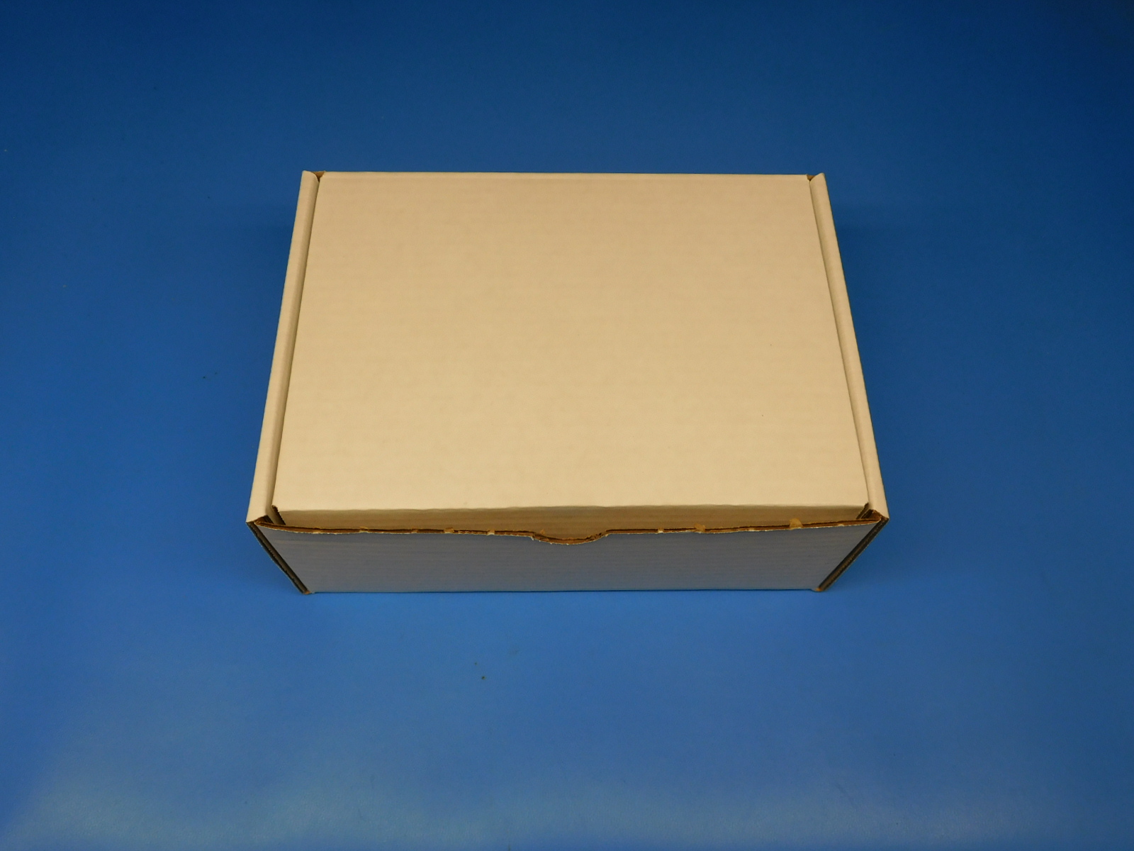
Now close the box and take it to the Uline tape machines.
Use [SH-PG0131] #260 White Reinforced Gummed Tape with LulzBot Printed Logo, 10 Pack.
Select the 12" length on the machine.
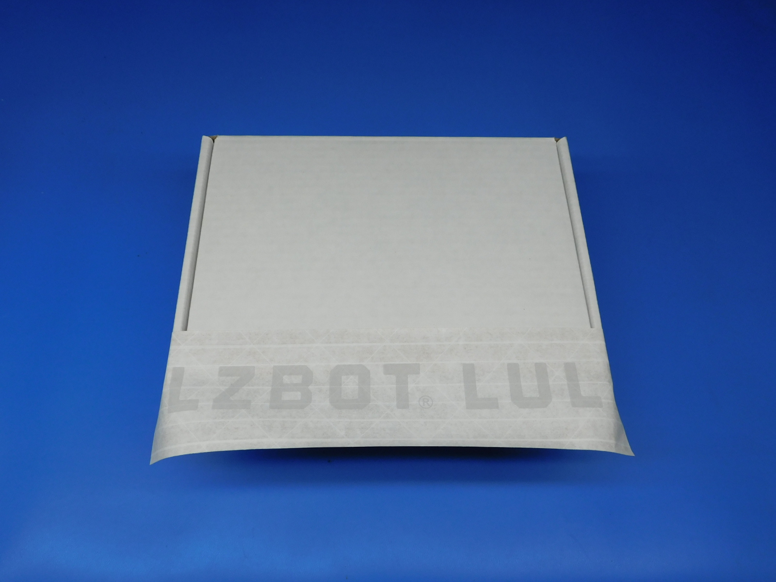
Place the tape with slightly more depth on the top of the box.
Now we will fold the sides inward.
Lastly, fold the tape down securing the lid of the box closed.
First place the Front label [DC-LB0168] to the front of the box. Next place the back label [DC-LB0169] to the back of the box. Then, add the [DC-MS0037] Colorado Made Green Sticker to the right side of the box, positioned in the top right corner. Finally, place the [DC-LB0174] P65 Warning Label on top.