Open HardwareAssembly Instructions
Guides for installation and assembly of the LulzBot line of products made by Aleph Objects, Inc.
Guides for installation and assembly of the LulzBot line of products made by Aleph Objects, Inc.
Materials required for AS-PR0169:
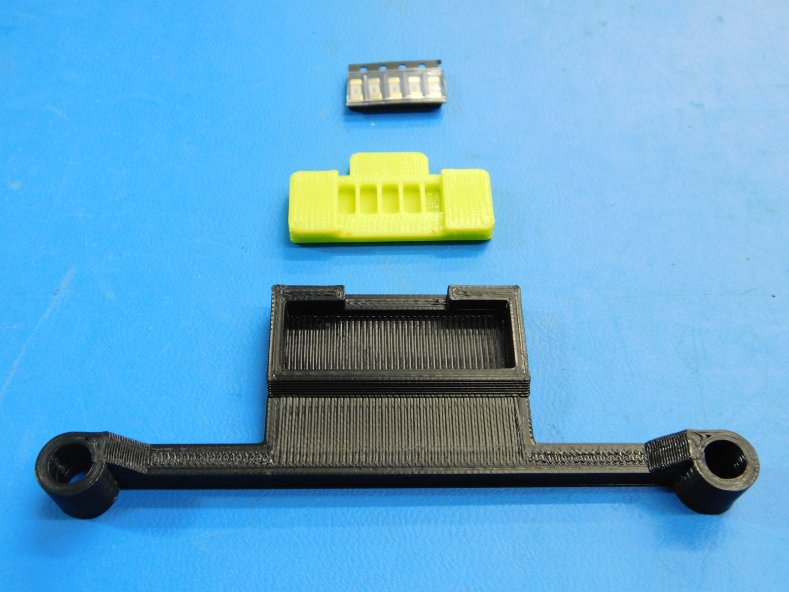
1x- [PP-GP0463] 5A Fuse Sleeve, LulzBot Green, Flexible
1x- [PP-GP0464] 5A Fuse Mount, Black
5x- [EL-MS0235] Surface Mount Fuses 125V V/FA 5A NANO2
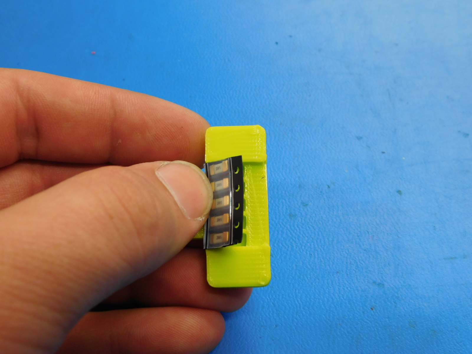
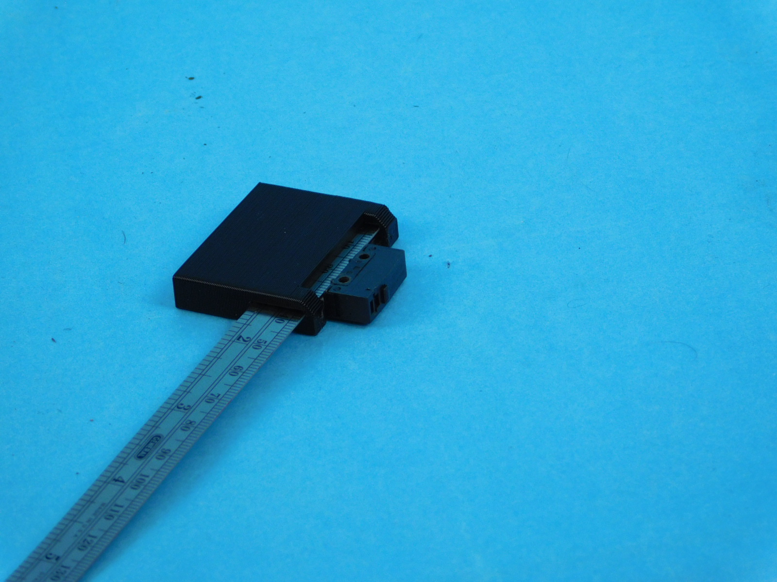
Cut a strip of 5 fuses [EL-MS0235] from the strip of fuses. Do not remove individual fuses from the strip
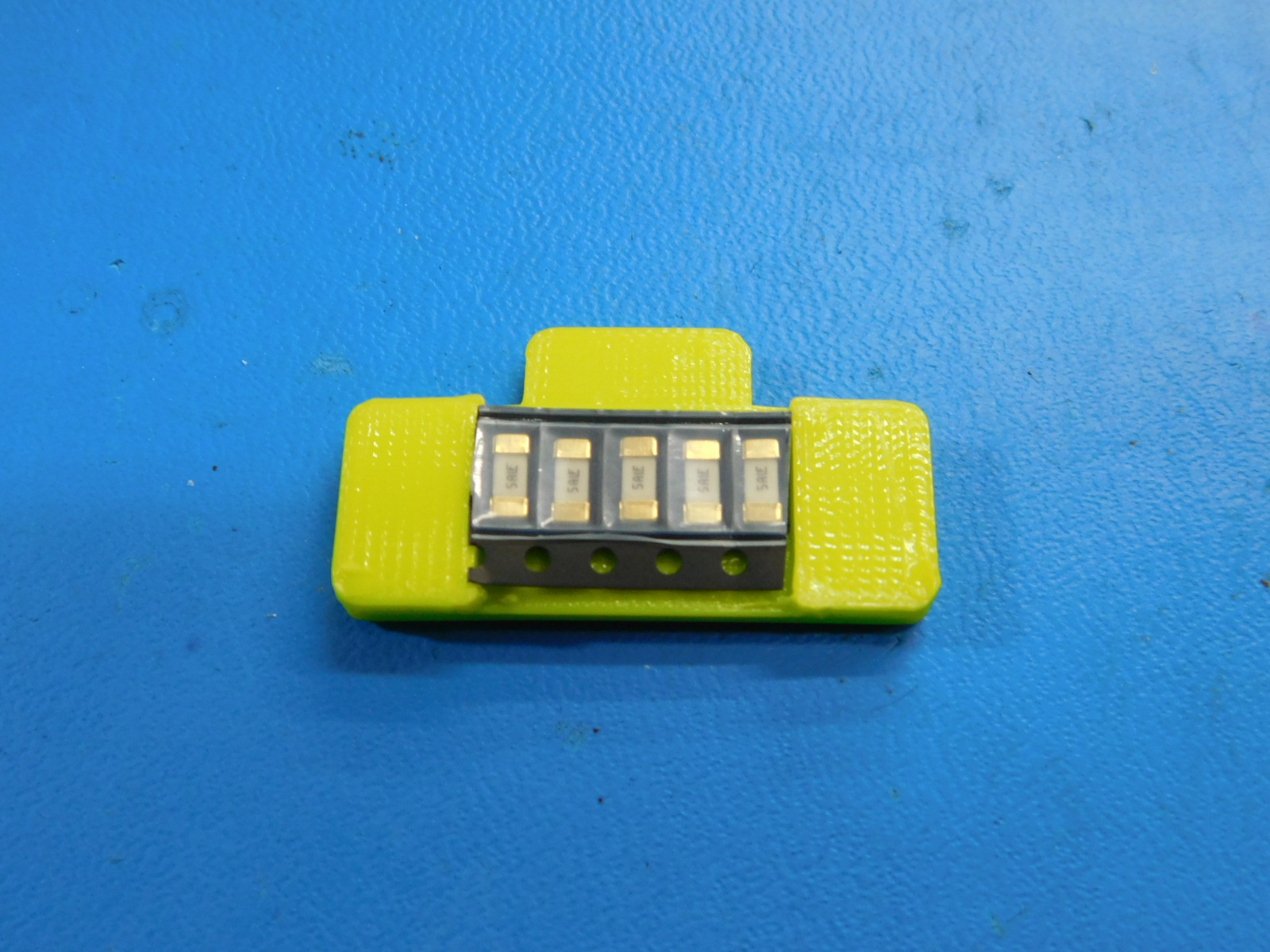
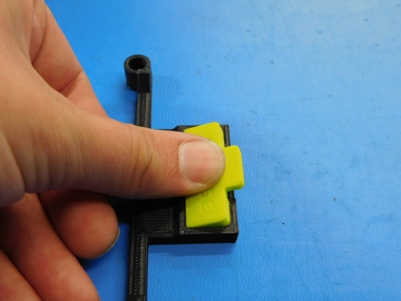
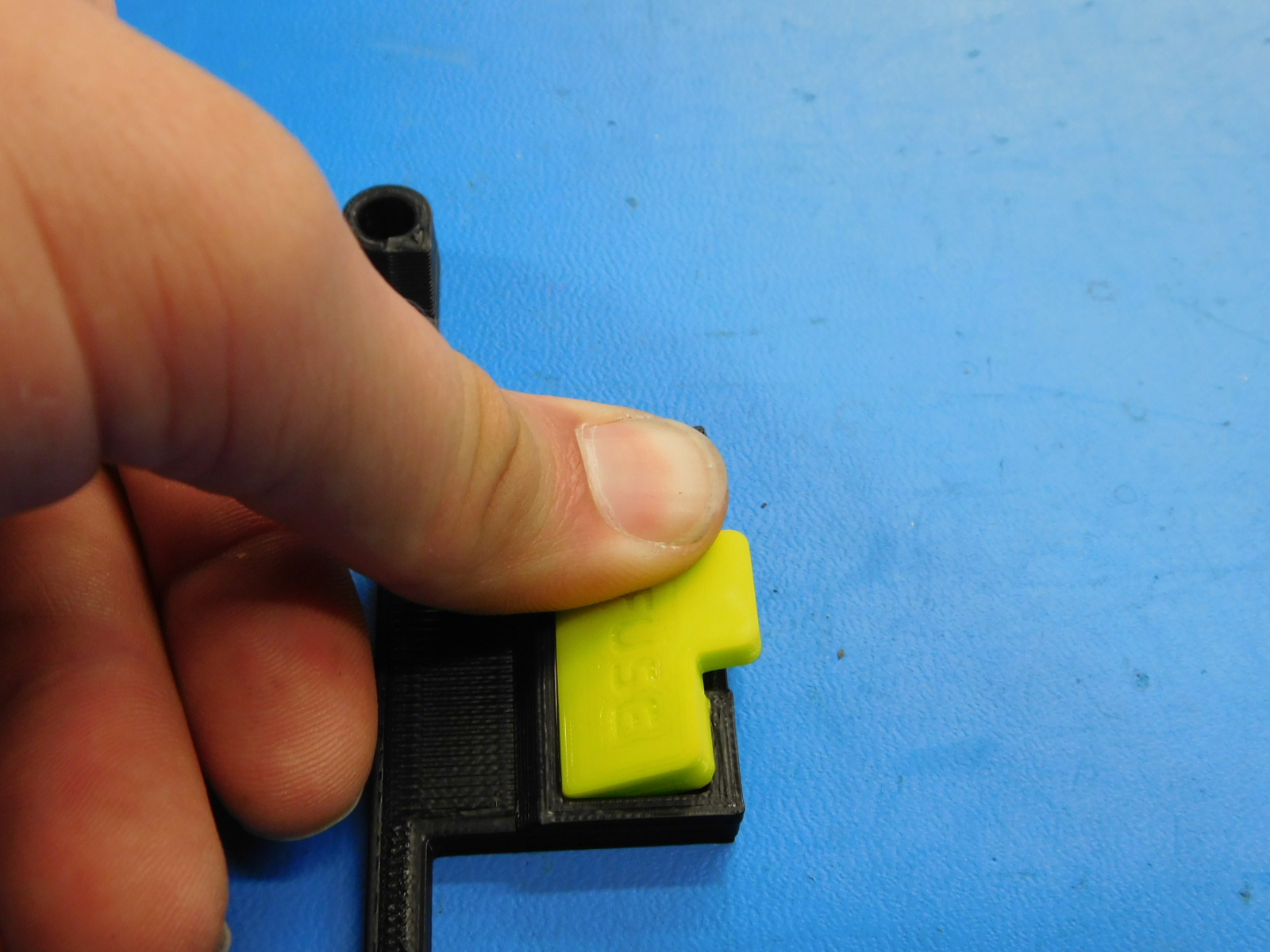
Insert the strip of 5 fuses into the Fuse Sleeve [PP-GP0463] as pictured.
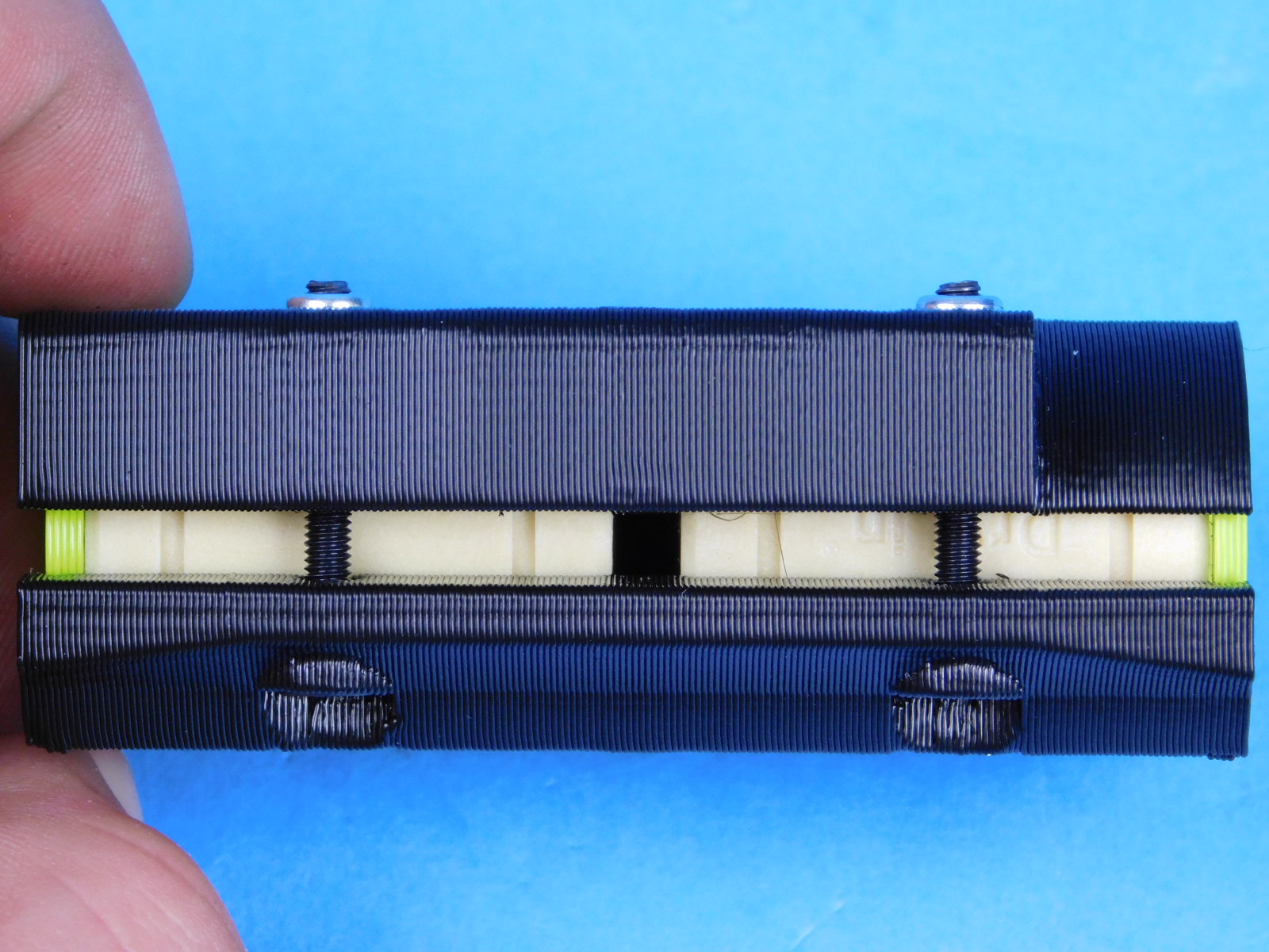
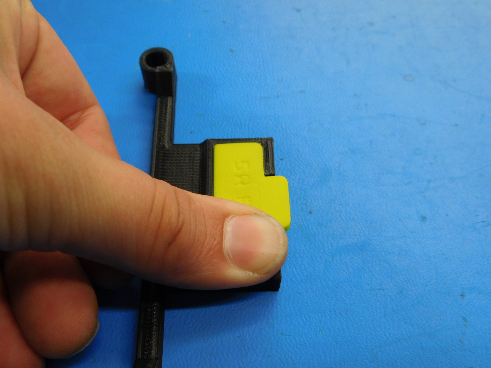
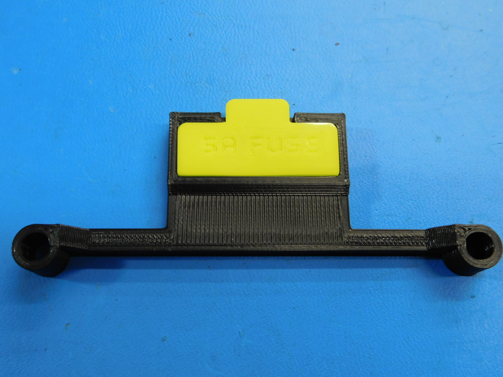
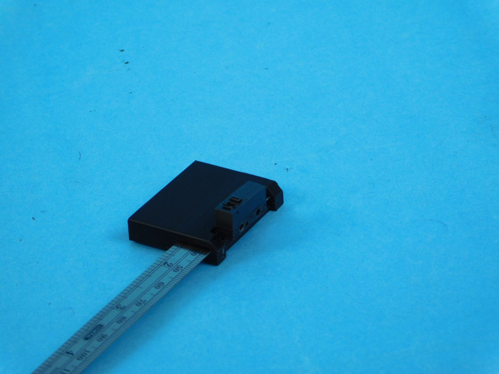
Press the Fuse Sleeve [PP-GP0463] with fuses into the Fuse Mount [PP-GP0464] as pictured.
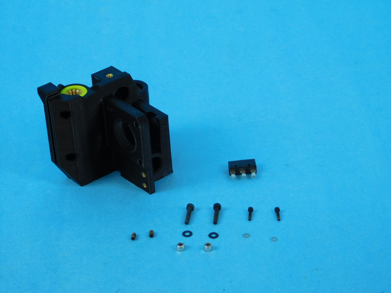
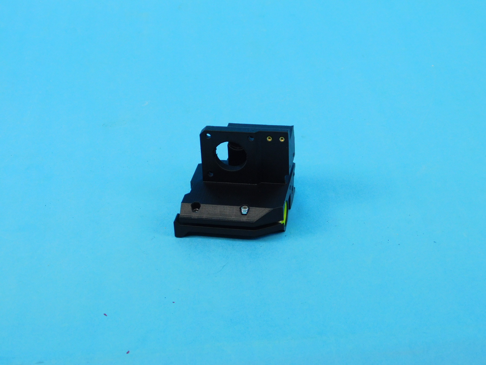
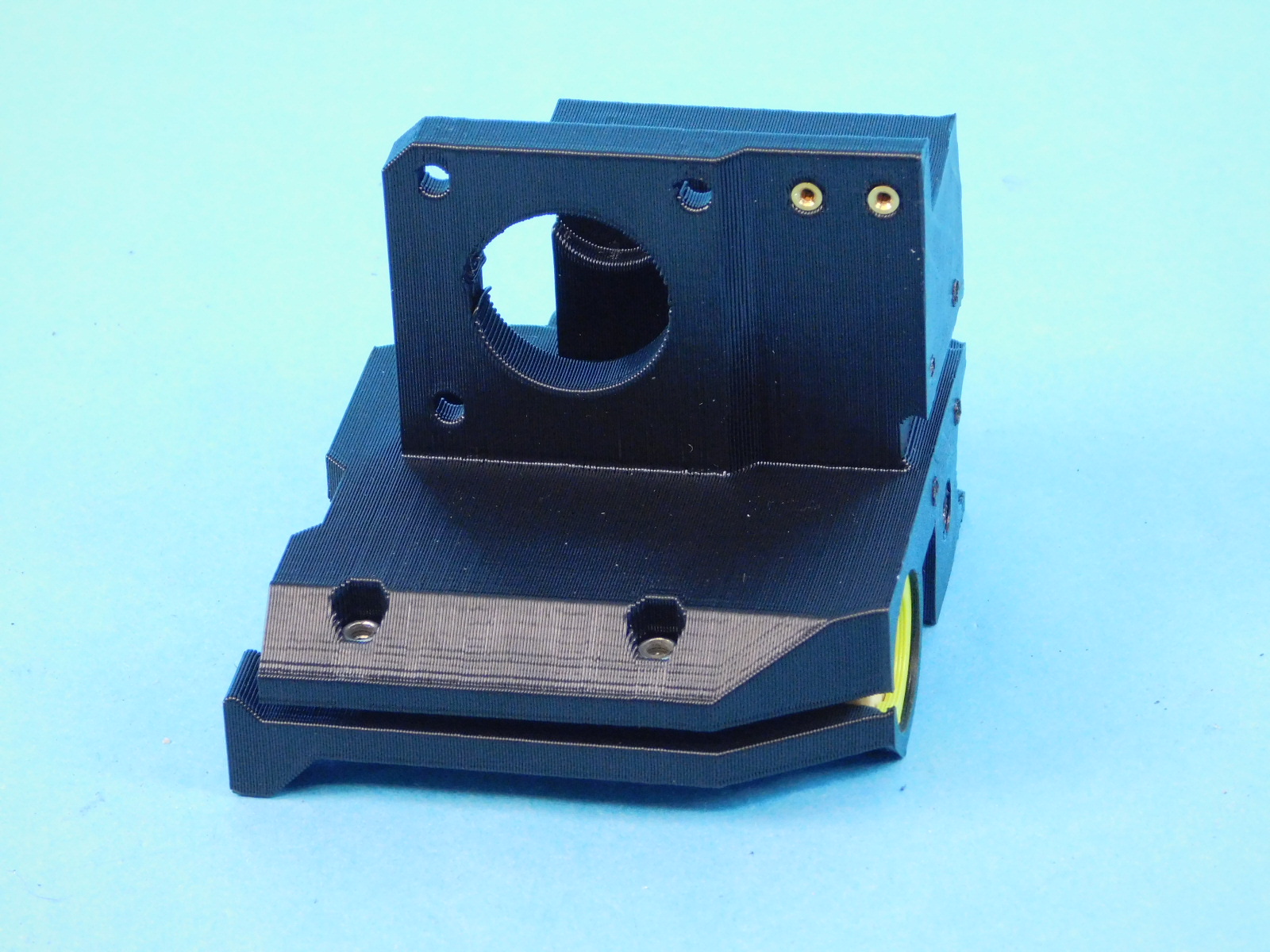
Materials for [AS-PR0160] X-End Motor Sub-Assembly:
Place 2X [HD-NT0001] Locknut into the nut trap of the compression holes of [AS-PR0156] x-motor with bushings.
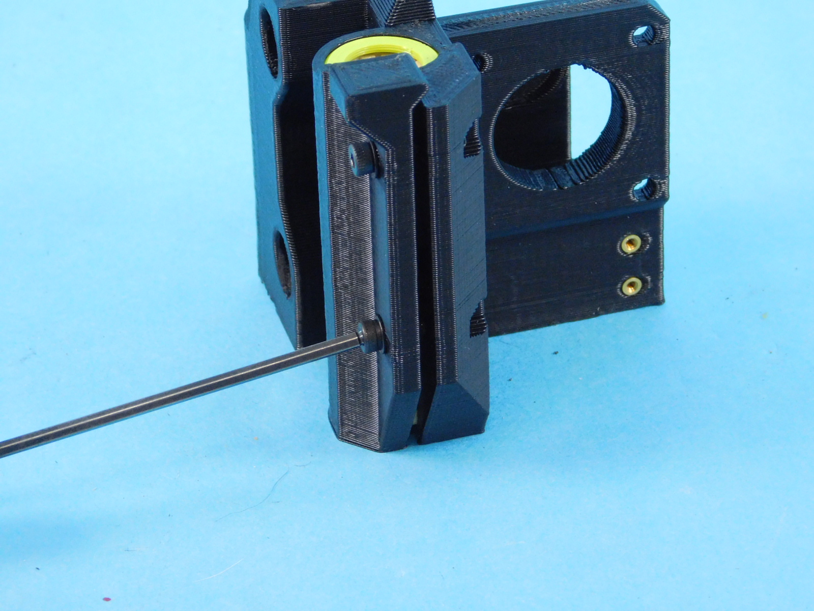
Insert 2X [HD-BT0185] M3X16 SHC fastener with [HD-WA0038] into the compression holes for the double bearing but do not tighten all the way.
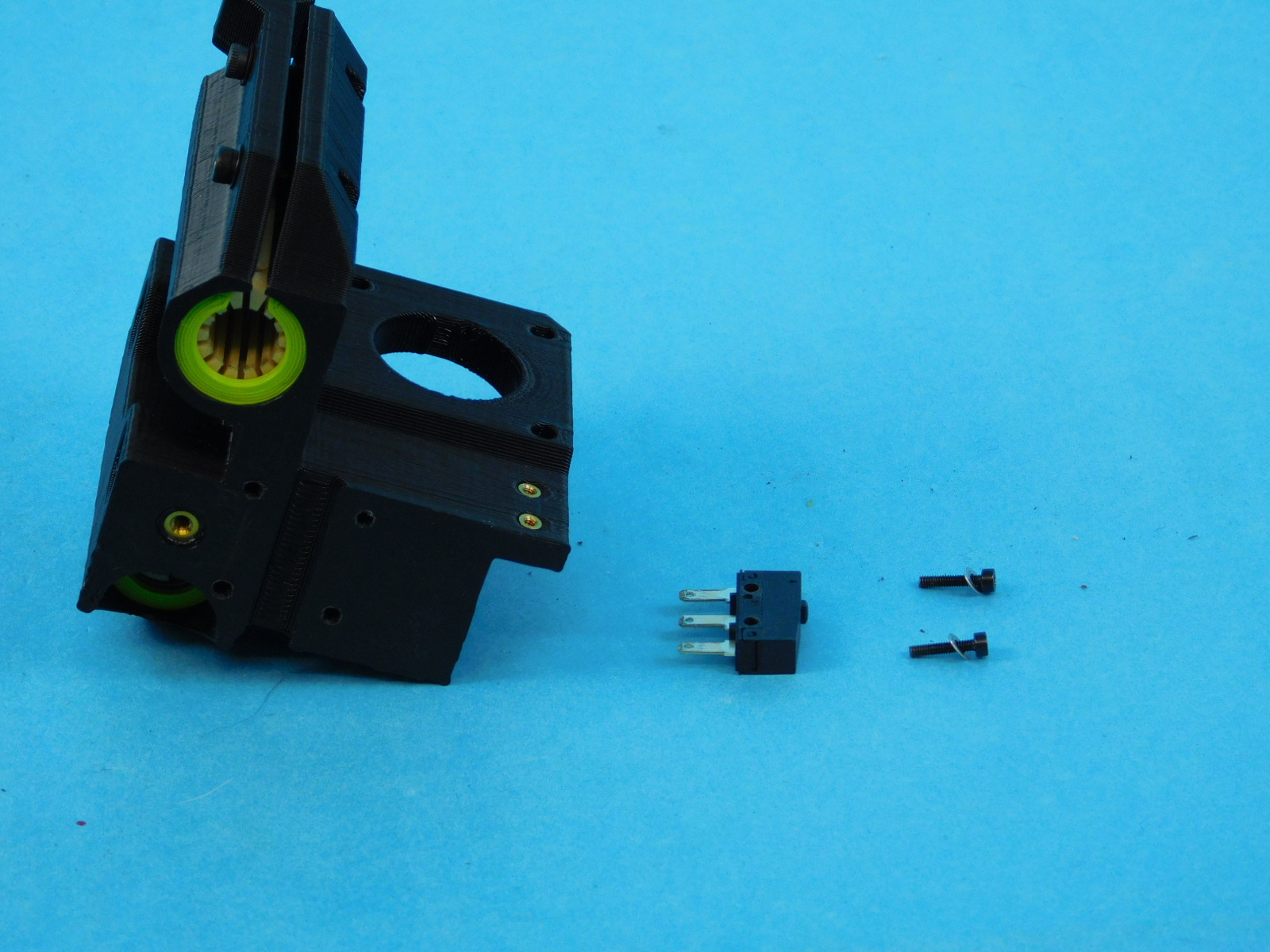
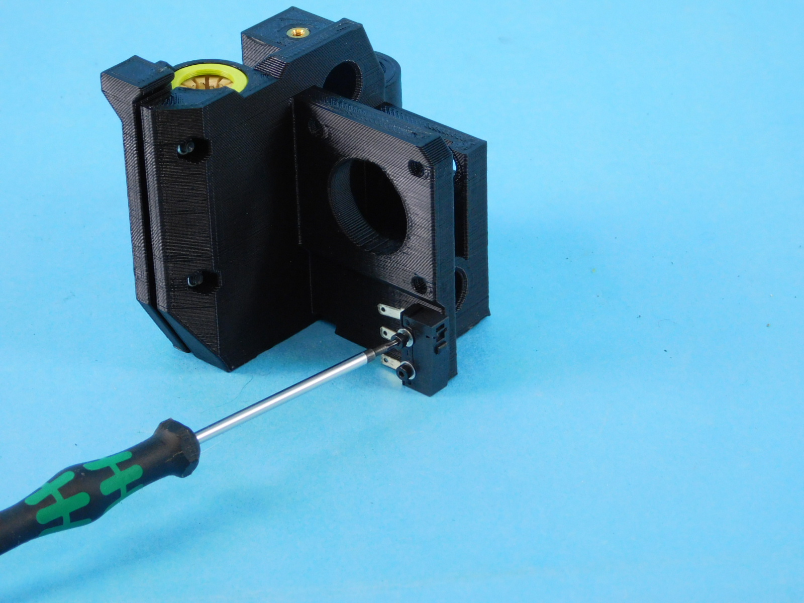
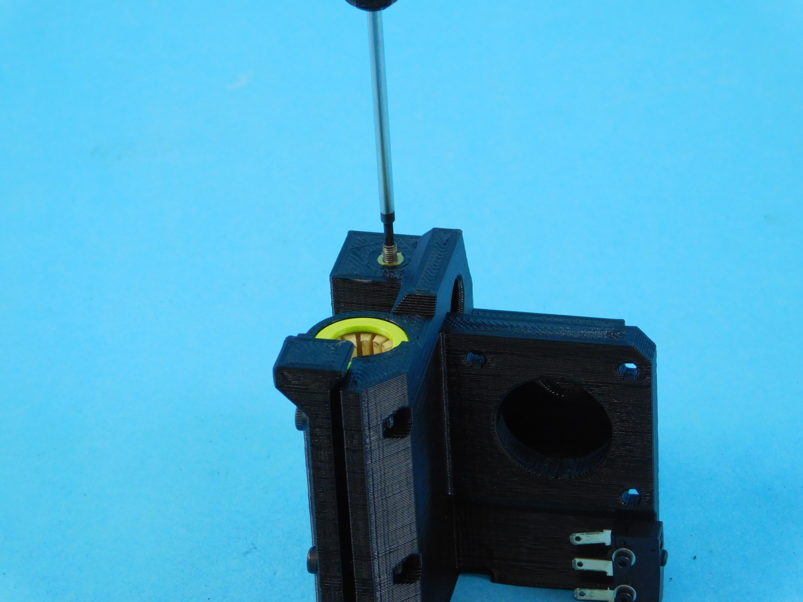
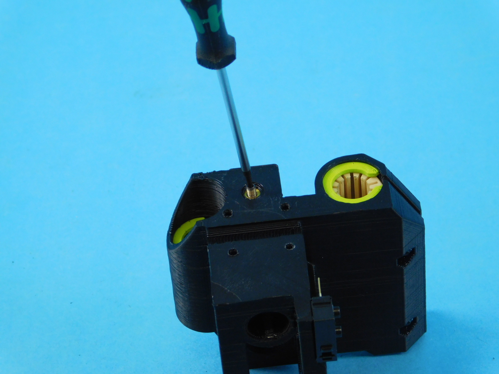
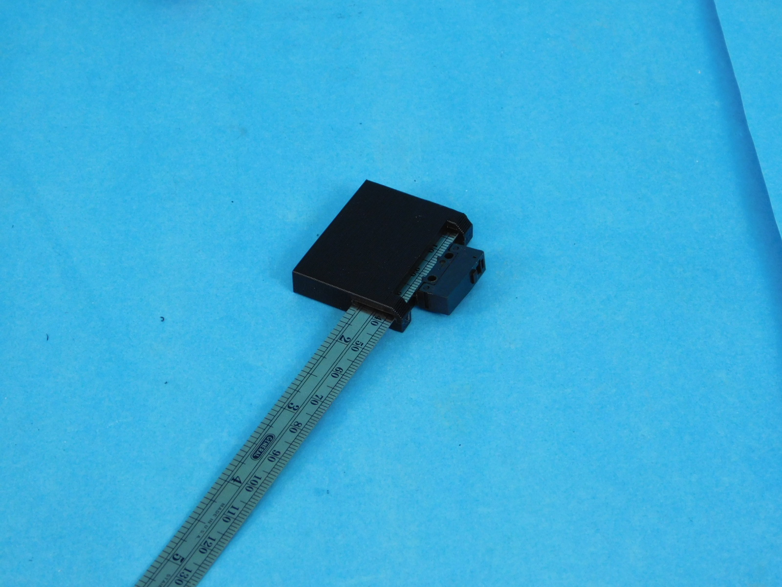
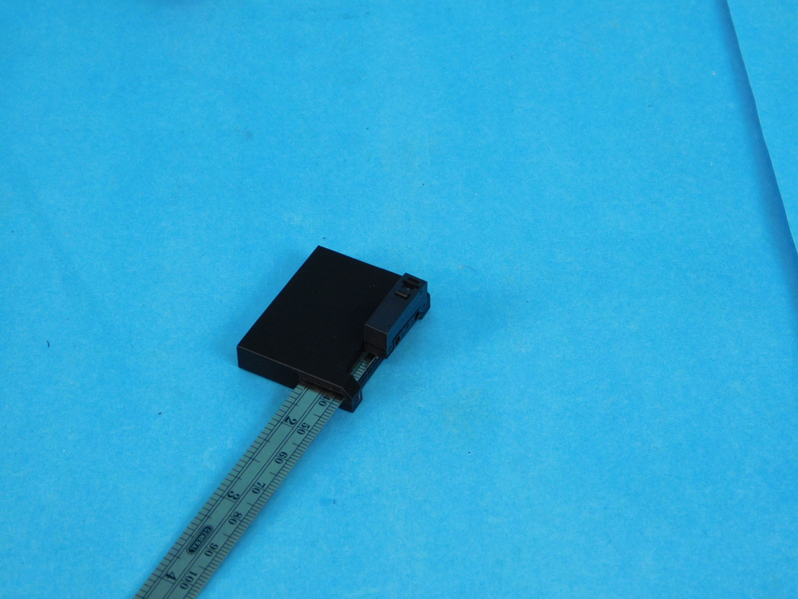
Install one switch [EL-SW0022] to the X Motor End with the tab facing the top of the part using two M2x10 SHCS [HD-BT0107] with washers [HD-WA0012]
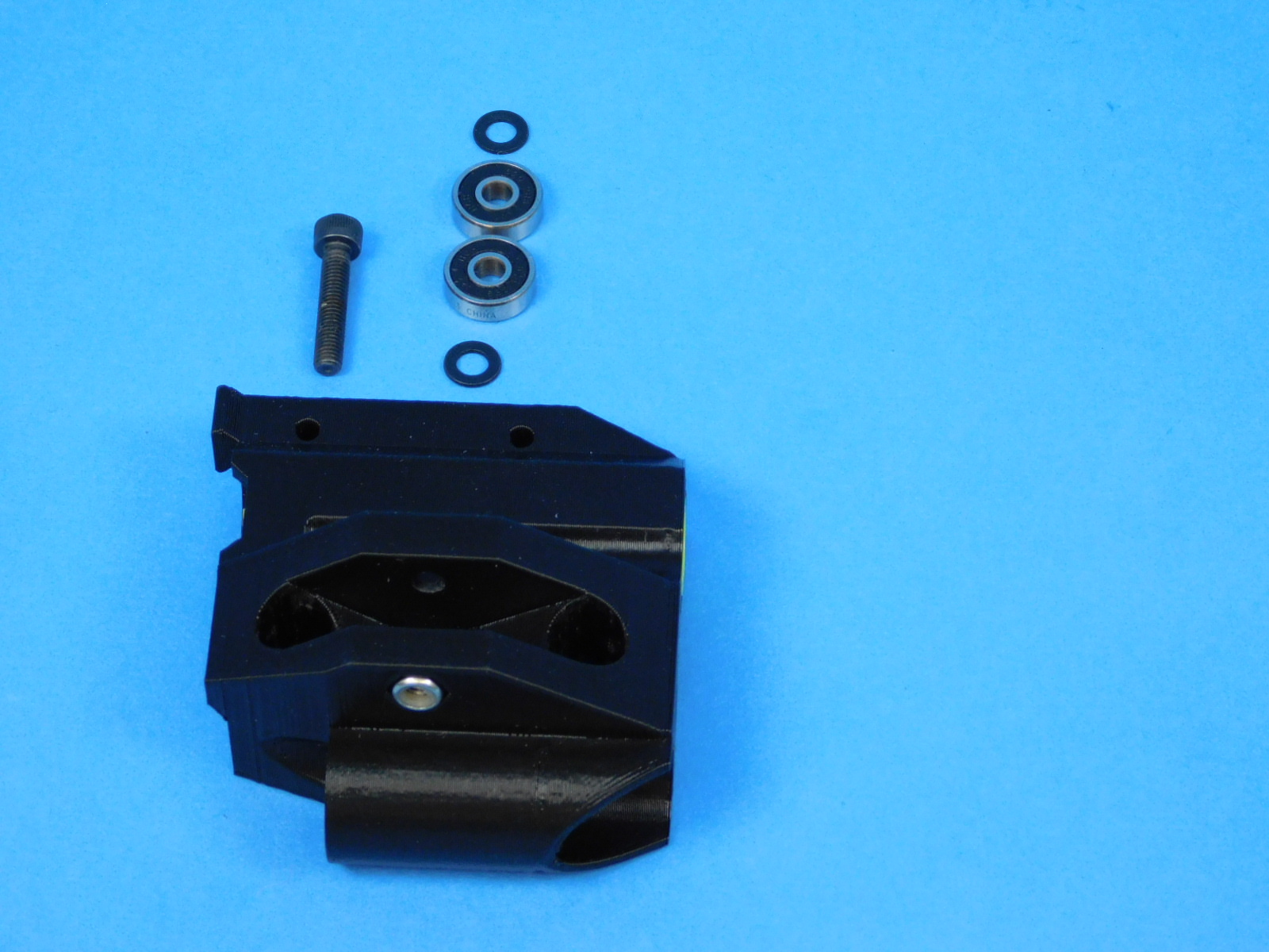
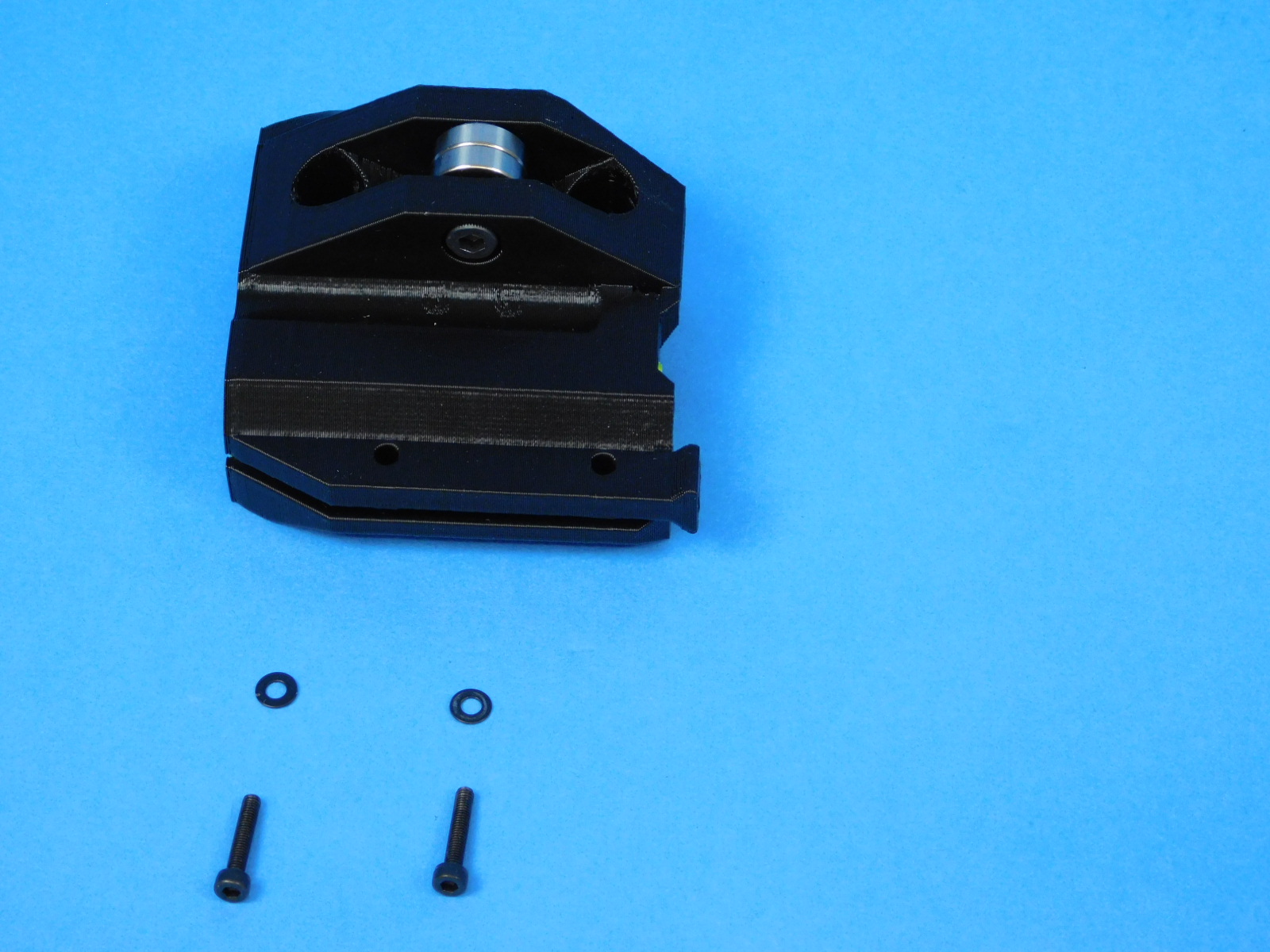
Materials for [AS-PR0127] X-End Idler Assembly:
Place one M5 Nyloc Nut [HD-NT0057] into the nut trap of the X-End Idler with Bushings [AS-PR0126]
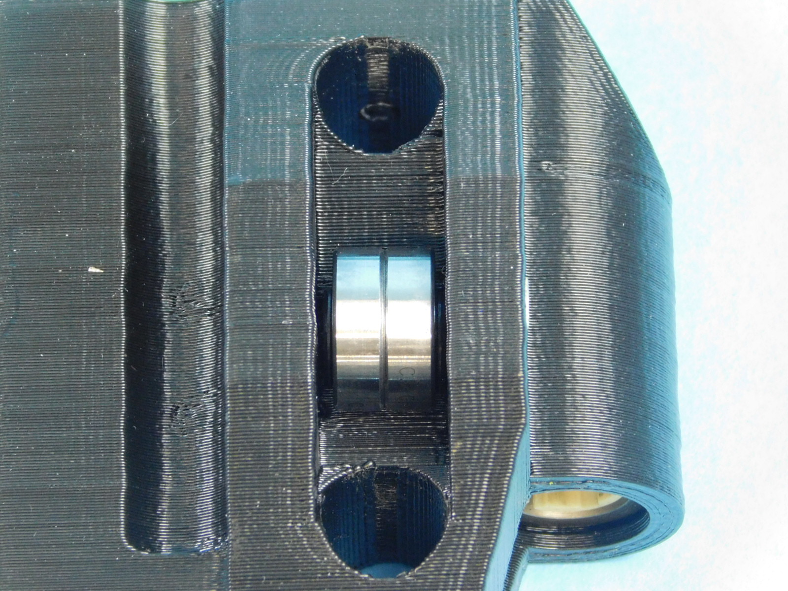
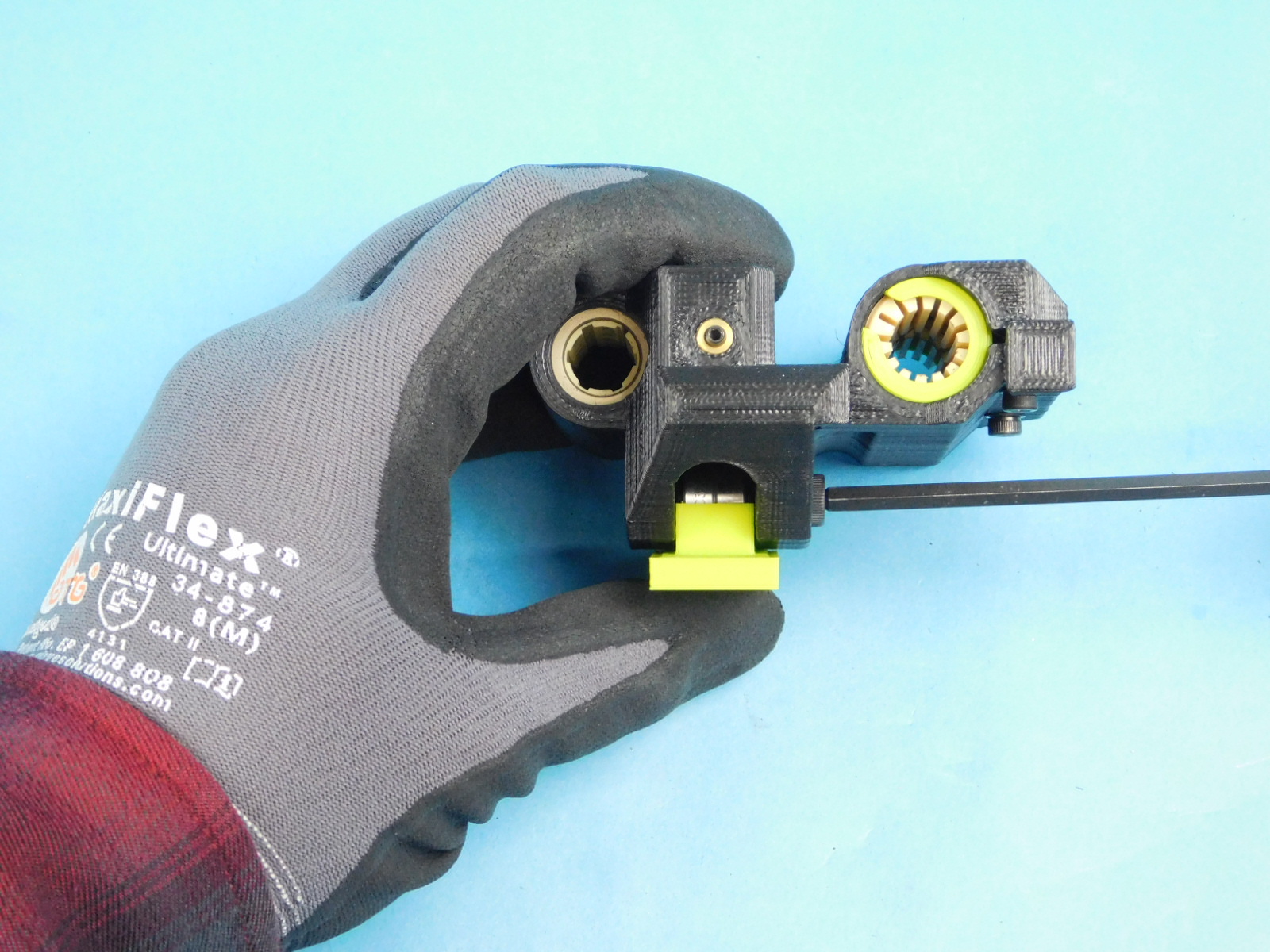
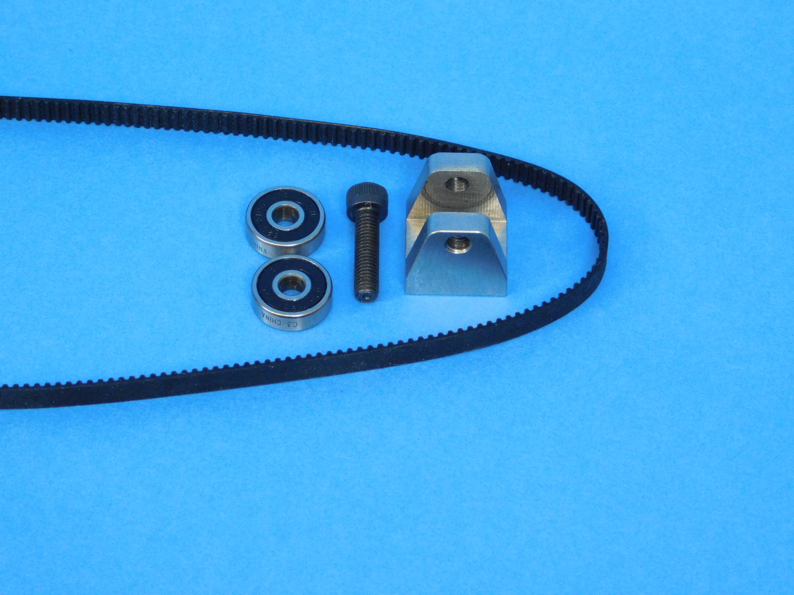
Place 2x [HD-MS0411] sealed bearings and 2x [HD-WA0040] M5 washers into the designated slot as shown.
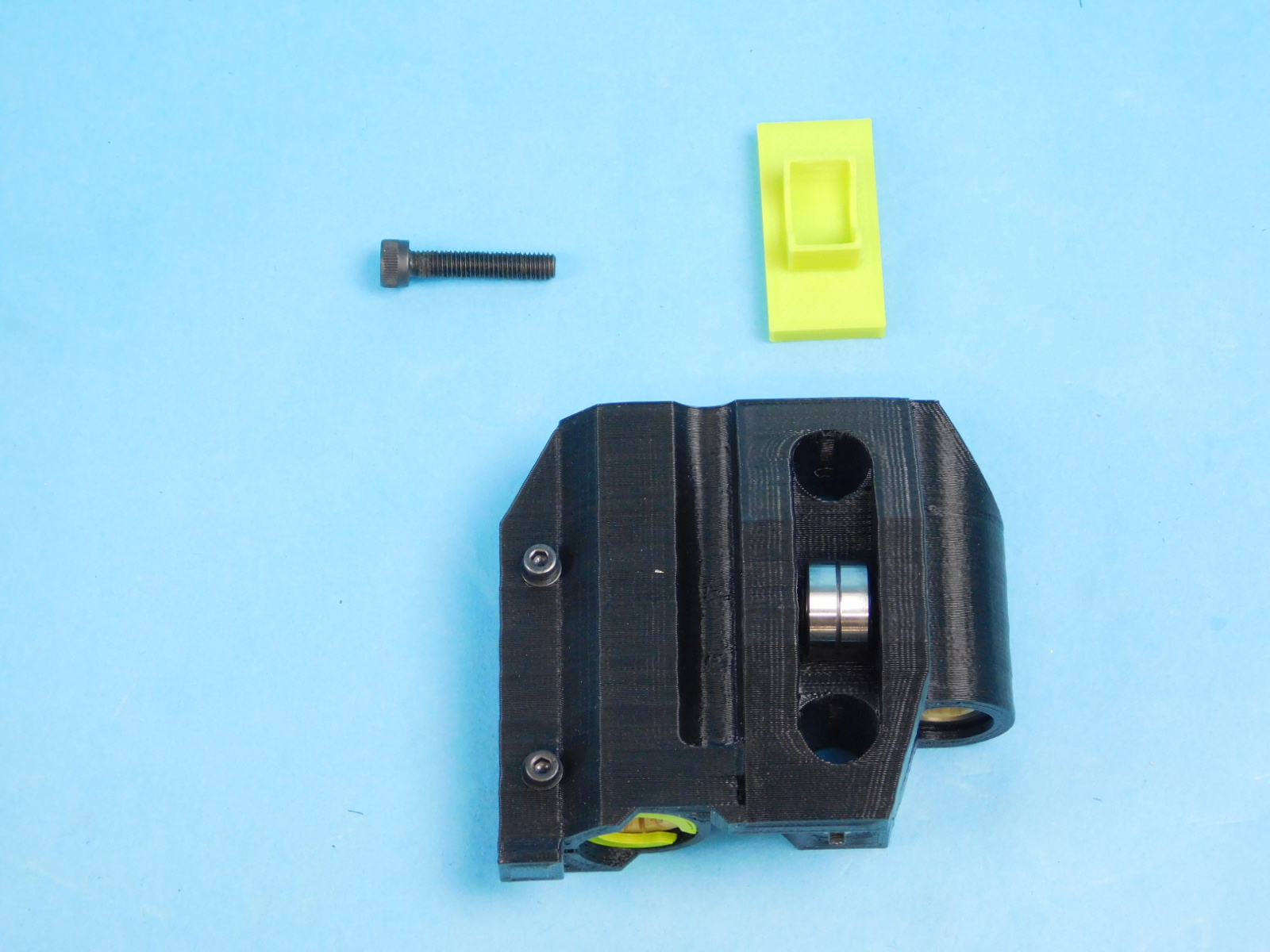
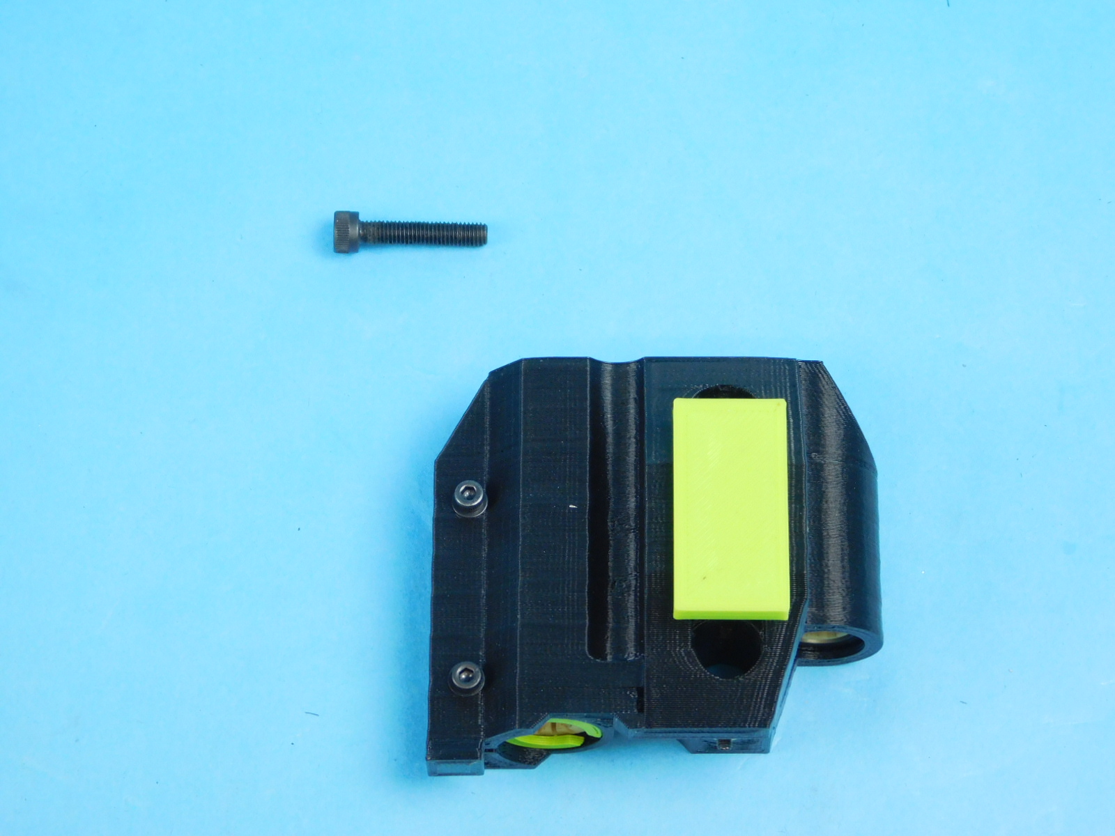
Place the printed bearing placement jig over the stack of bearings and washers.
Turn the part over so that the bearings and washers fall into the printed jig.
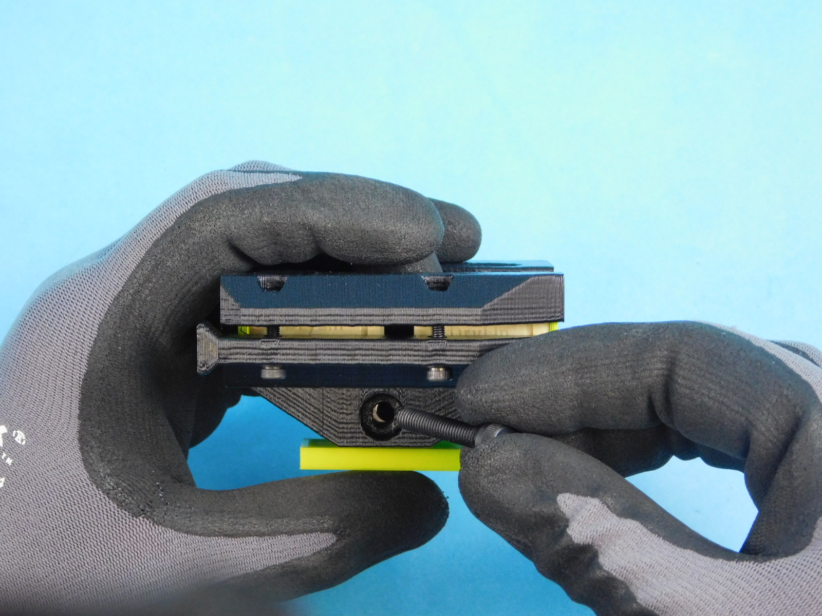
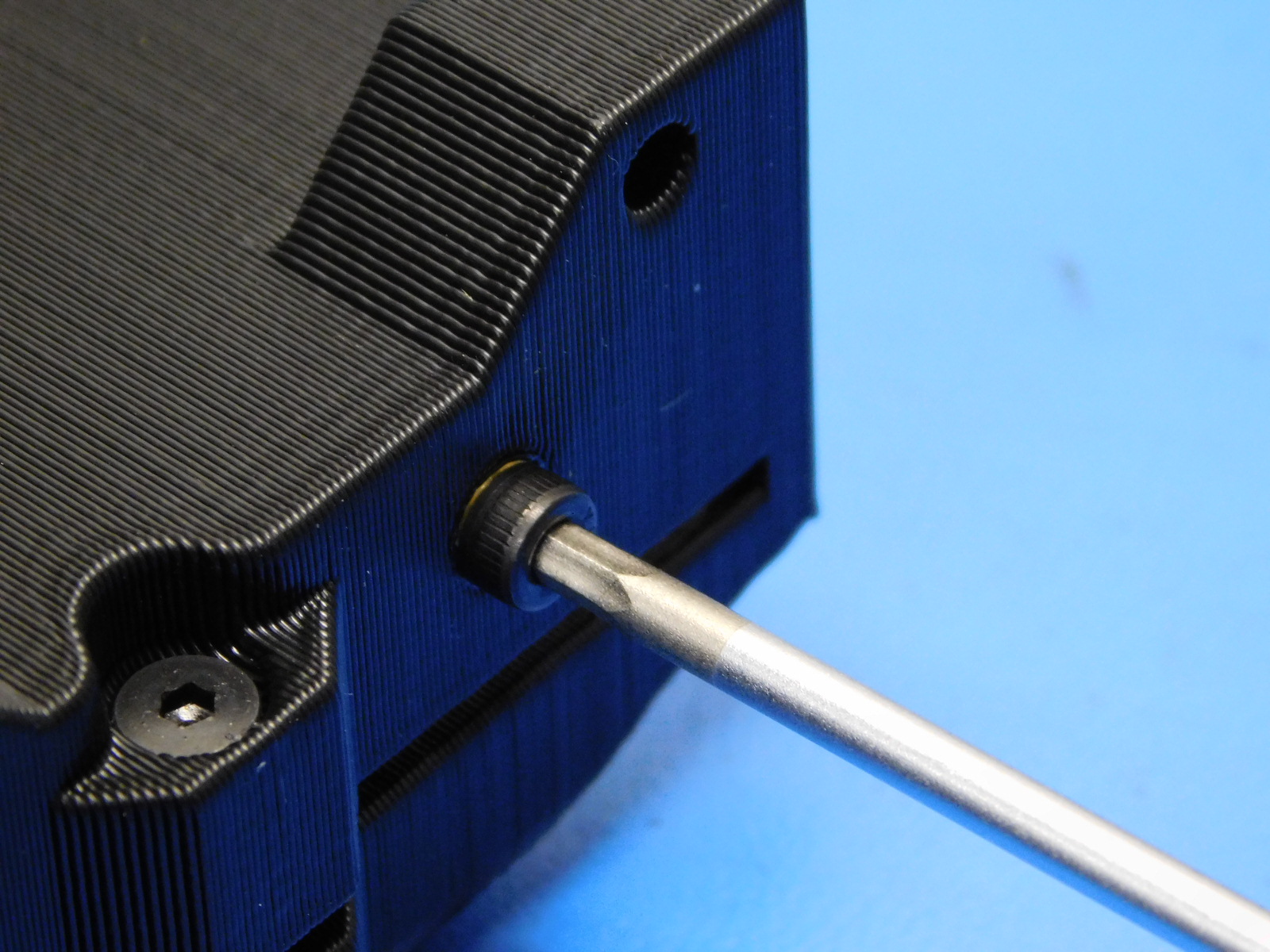
Install 1x [HD-BT0196] M5x25 SHCS until it is flush with the back of the M5 Nyloc Nut
Be careful to not over tighten this part.
Place 2X [HD-NT0001] Locknut into the nut trap of the compression holes of [AS-PR0126] X-End Idler with bushings.
Insert 2X [HD-BT0185] M3X16 SHCS fastener with [HD-WA0038] into the compression holes for the double bearing but do not tighten all the way.
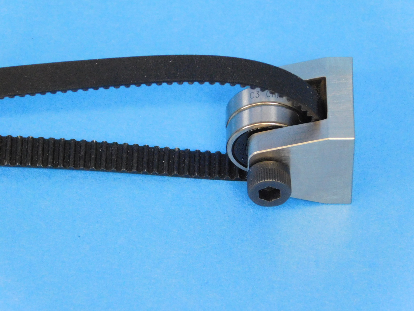
Materials for [AS-PR0129] Z Idler Assembly
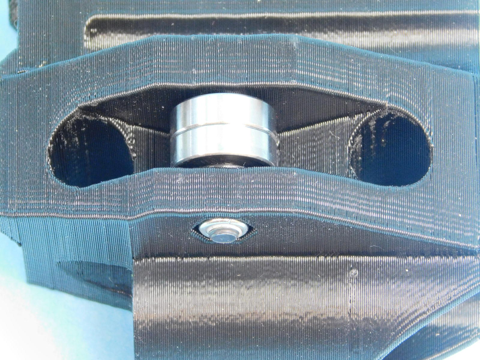
Place the [HD-BL0023] rubber belt's smoothed side against the back of the [PP-MP0225] YZ idler.
Fasten 1X [HD-BT0151] M5X20 SCHS into the YZ idler and through 2X [HD-MS0411] rubber sealed bearing.
Bend the switch tabs at a 90 degree angle using the provided jig.
Note orientation of the switch button in relation to the direction the tabs are bent, these are opposite for Z-Upper Left & Z-Upper Right.
Fasten one Z-max switch [EL-SW0022] to the Z-Upper [PP-IS0093] using 2x M2X10 SHCs [HD-BT0107] with washers [HD-WA0012], as pictured.
Ensure the button of the switch is closest to the round smooth rod holes of the printed part.
Fasten the Z-upper top plate [PP-FP0156] to the Z-upper right with inserts [PP-IS0093] using 4x M3X10 FHCS [HD-BT0116]
Torque to 5in*lbs
Install 2x M3 Set Screws [HD-BT0012] on to the top of the z-upper top plate.
Bend the switch tabs at a 90 degree angle using the provided jig.
Note orientation of the switch button in relation to the direction the tabs are bent, these are opposite for Z-Upper Left & Z-Upper Right.
Fasten one Z-max switch [EL-SW0022] to the Z-Upper using 2x M2X10 SHCs [HD-BT0107] with washers [HD-WA0012], as pictured.
Ensure the button of the switch is closest to the round smooth rod holes of the printed part.
Fasten the Z-upper top plate [PP-FP0156] to the Z-upper left with inserts [PP-IS0094] using 4x M3X10 FHCS [HD-BT0116]
Torque to 5in*lbs
Install 2x M3 Set Screws [HD-BT0012] on to the top of the z-upper top plate.
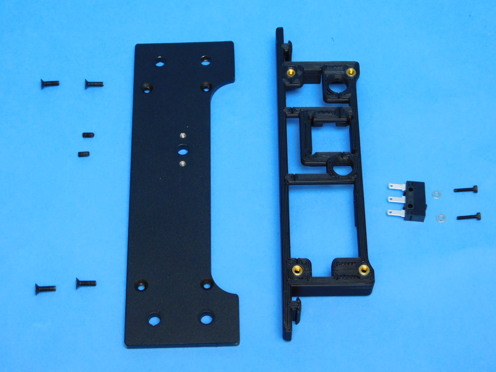

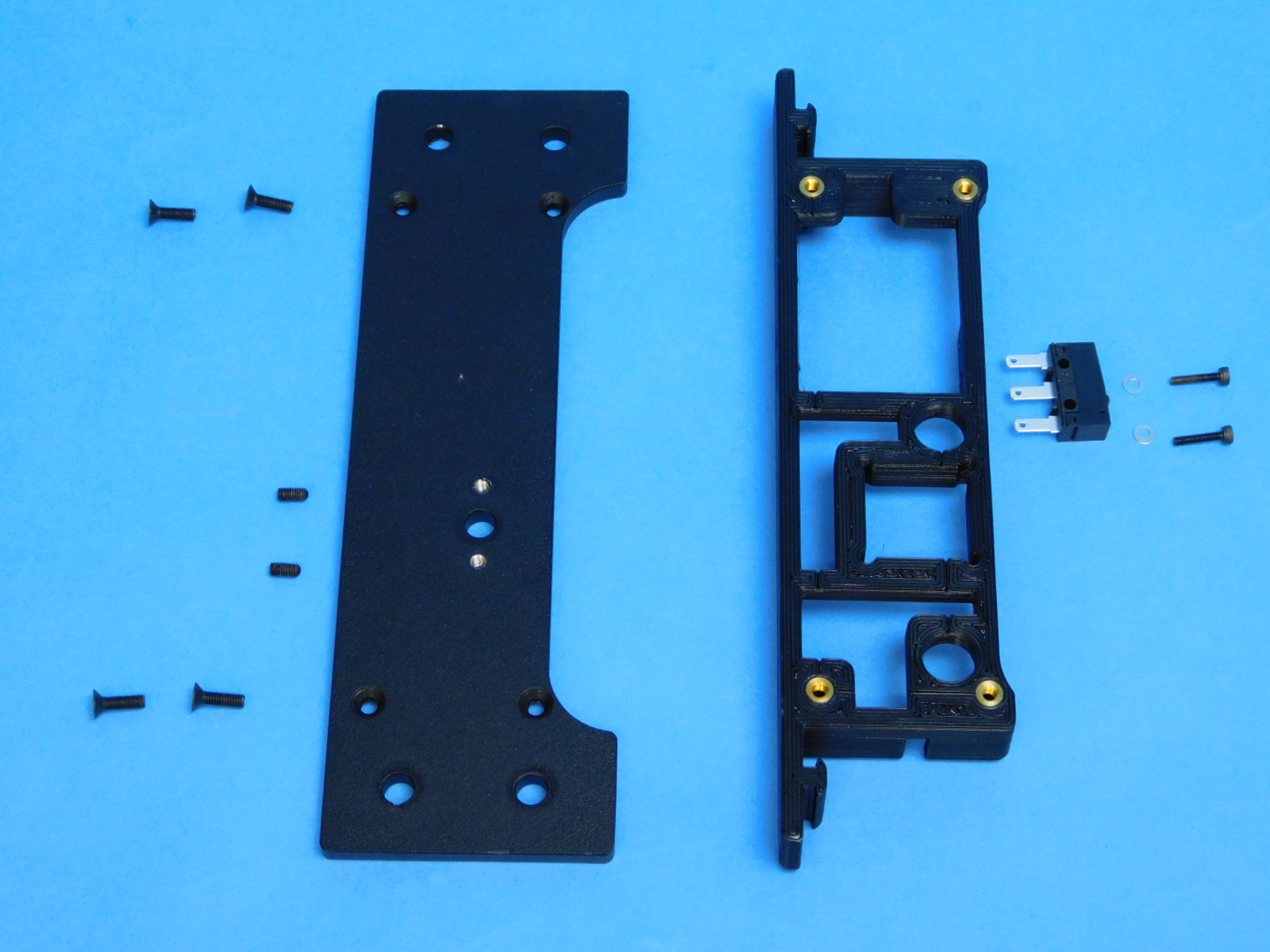
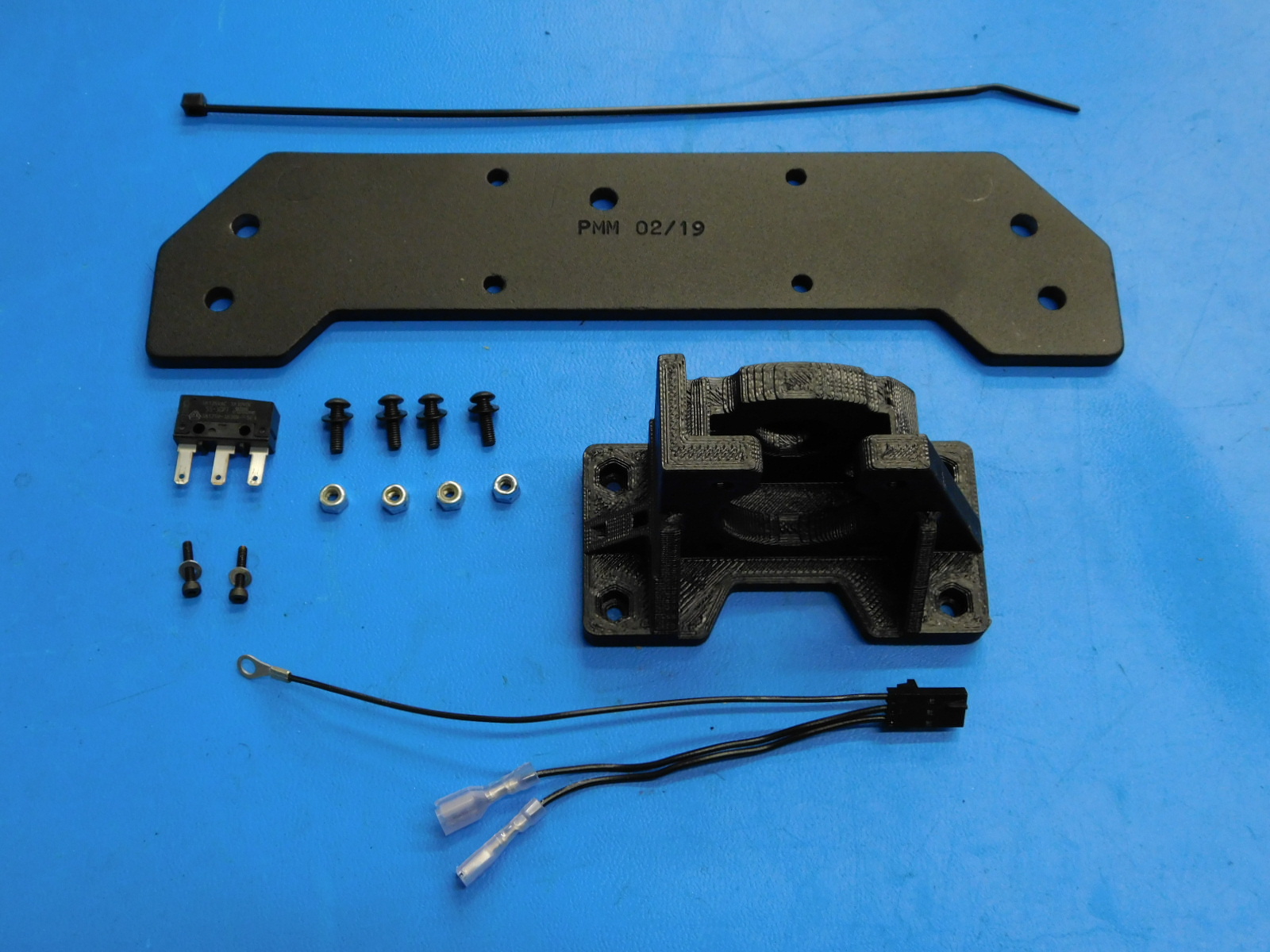
Materials required for [AS-PR0161] Y-Motor Mount Assembly:
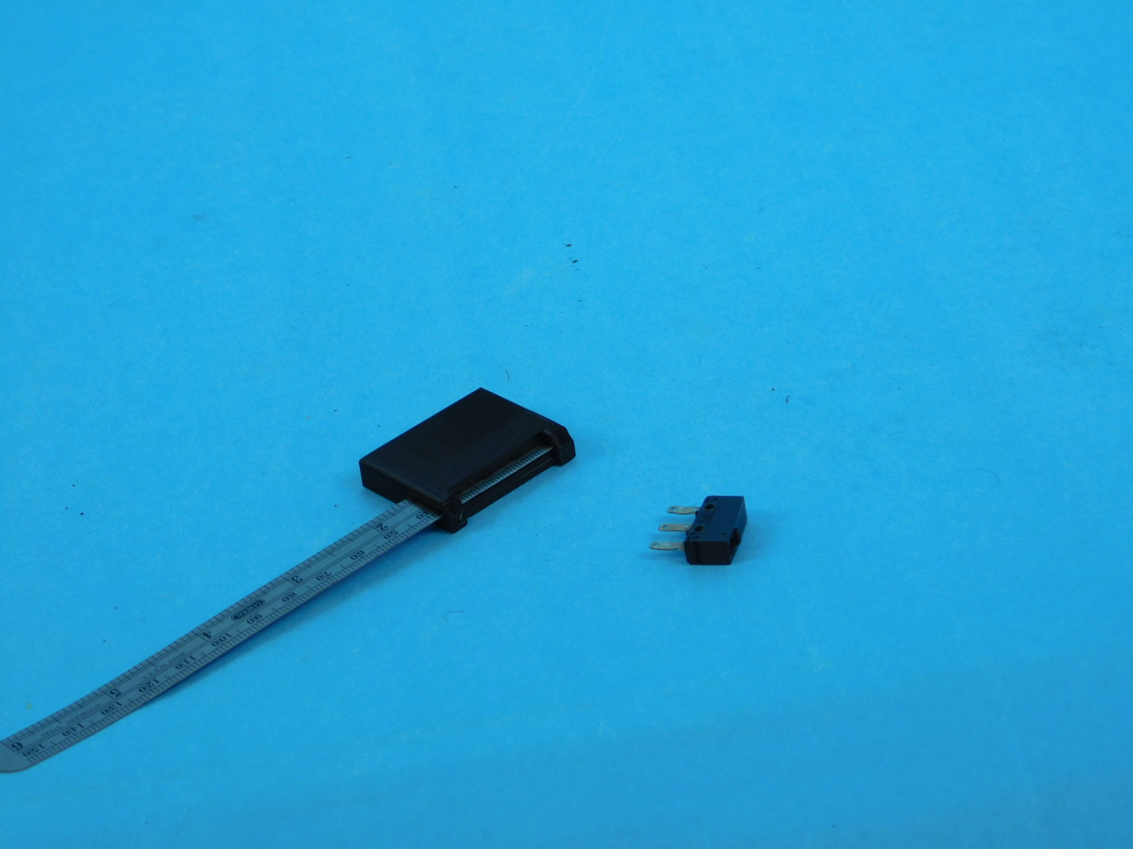
1x- [EL-SW0022] SWITCH BASIC SPDT 3A .110QC 125V
2x- [HD-BT0107] Metric Class 12.9 Socket Head Cap Screw Alloy Steel, Black, M2 Thread, 10mm Length, 0.4mm Pitch
4x- [HD-BT0148] Class 10.9 Steel Button-Head Socket Cap Screw, M3 Size, 10 mm Length, .5 mm Pitch
1x- [HD-MS0058] Wire Tie, 8" Black, pk 1000
4x- [HD-NT0001] Metric Zinc-Plated Steel Nylon-Insert Locknut, Class 8, M3 Screw sz, .5MM pitch, 5.5MM W, 4MM H
2x- [HD-WA0012] Steel Flat Washer, DIN 125 zinc-plated class 4,M2 screw sz, 5mm OD, .25mm-.35mm thick
4x- [HD-WA0038] Black-Oxide 18-8 Steel Flat Washer, M3 Screw Size, 3.2mm ID, 7.0mm OD
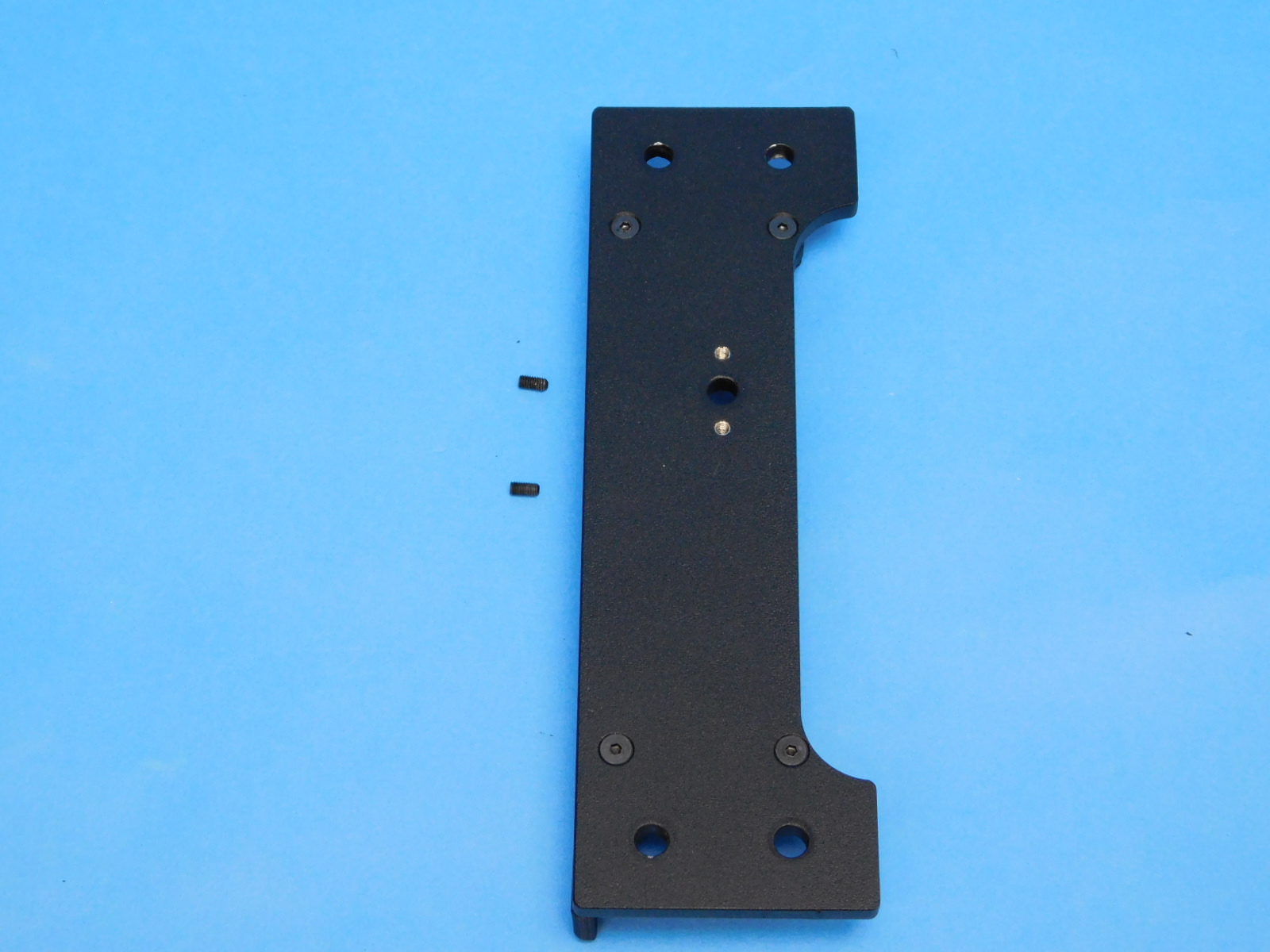
1x- [PP-FP0151] Y Endplate
1x- [EL-HR0182] TAZ Redgum, Y Motor Ground Extension
1x- [PP-IS0115] Y-Motor Mount with inserts
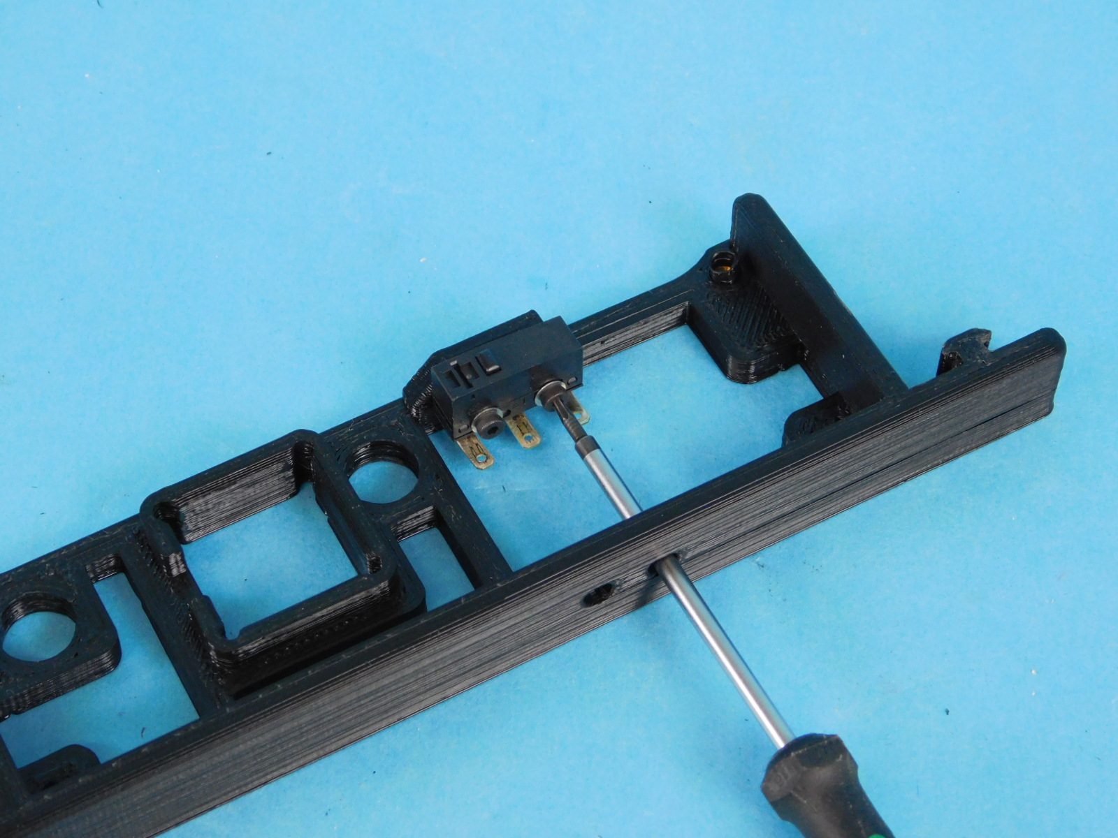
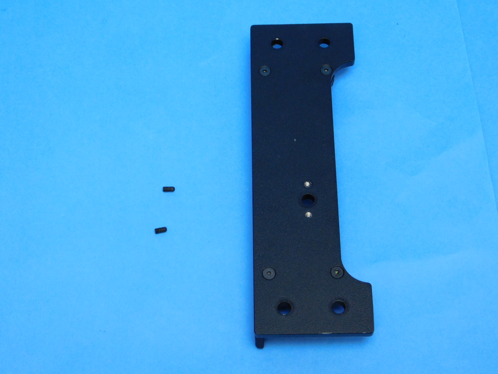
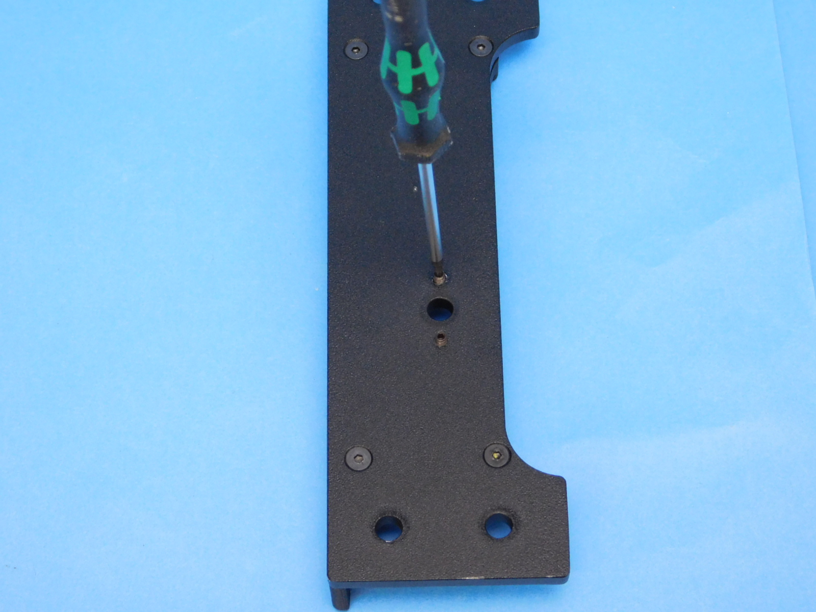
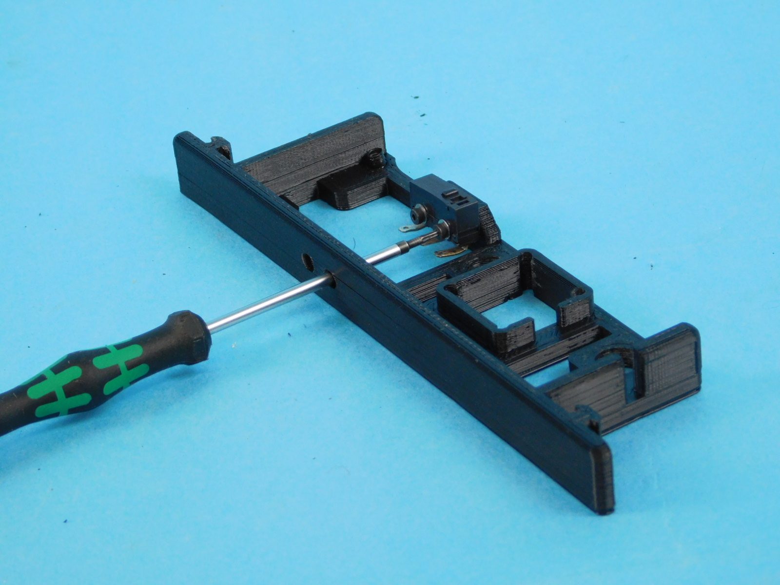
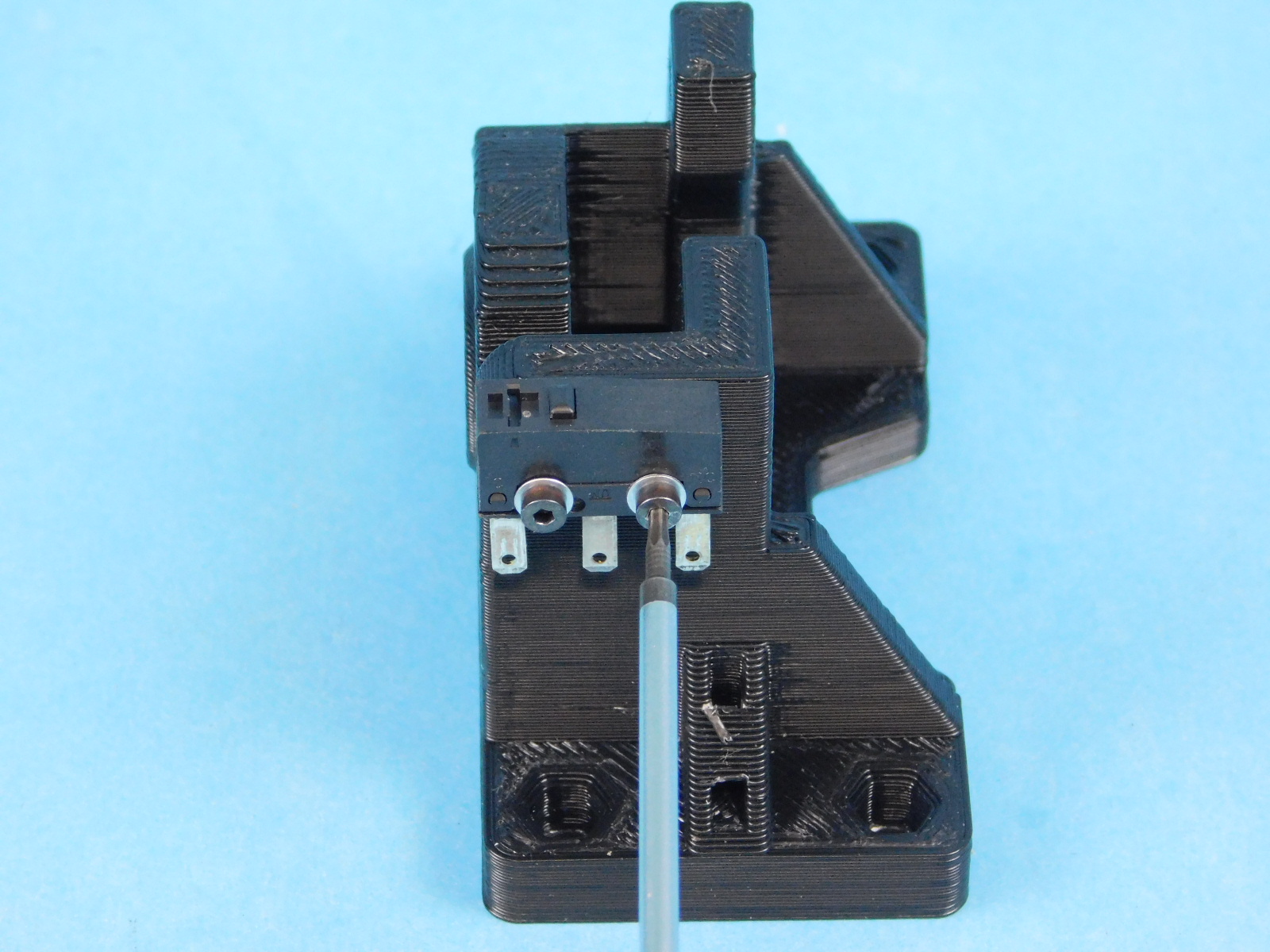
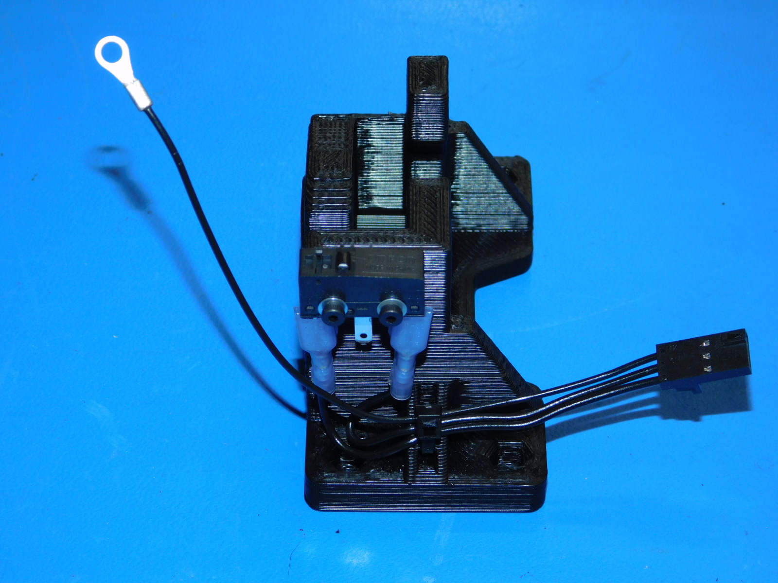
Attach one switch [EL-SW0022] to the Y Motor Mount with Inserts [PP-IS0115] with the switch button facing the top of the part using two M2x10 SHCS [HD-BT0107] with washers [HD-WA0012]
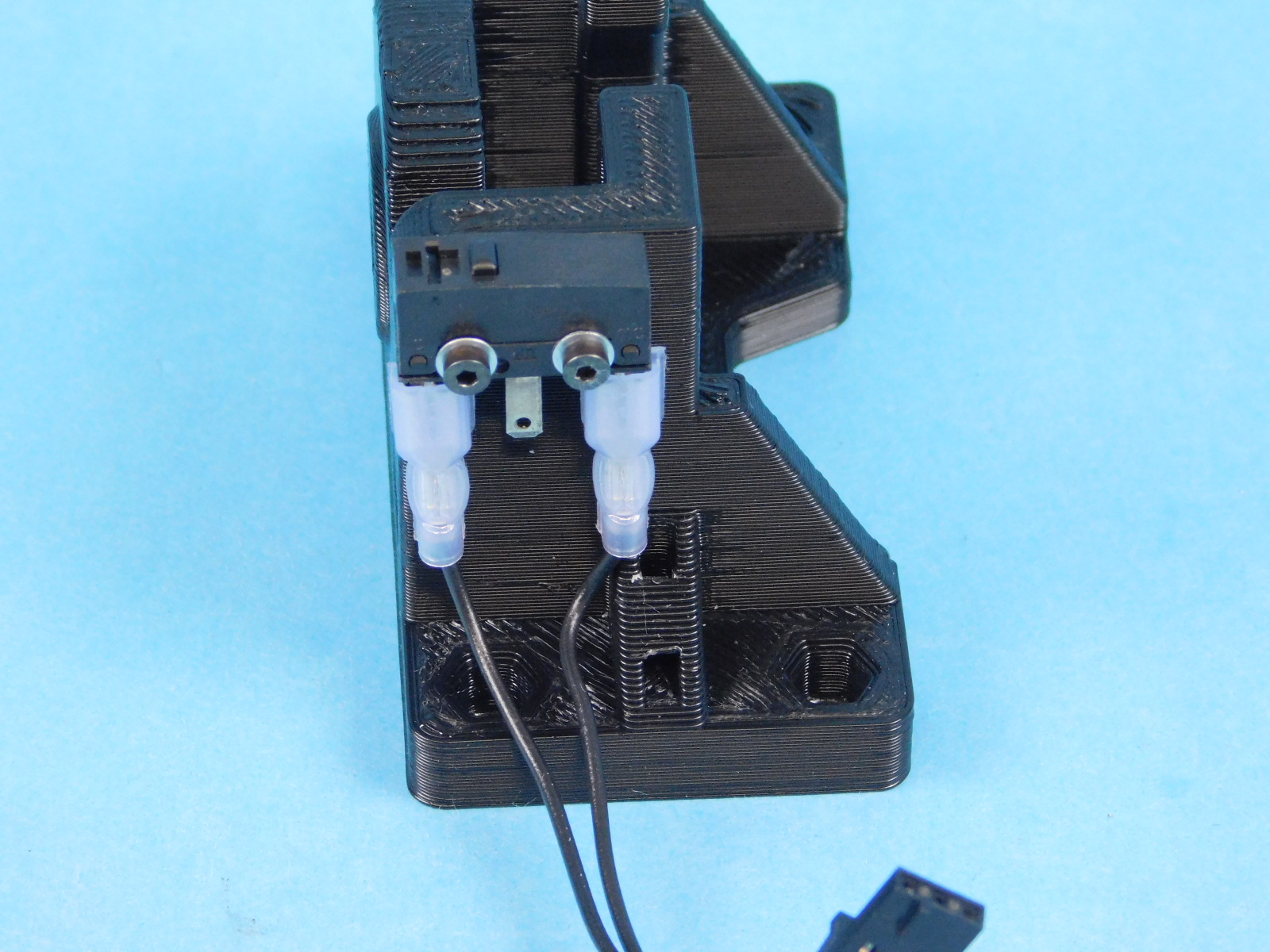
Connect the purple quick connects from the Y Motor Ground Extension [EL-HR0182] to the outer two tabs of the switch.
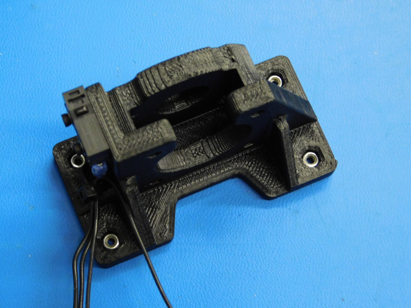
Secure the harness to the Y Motor Mount as pictured using one zip tie [HD-MS0058]
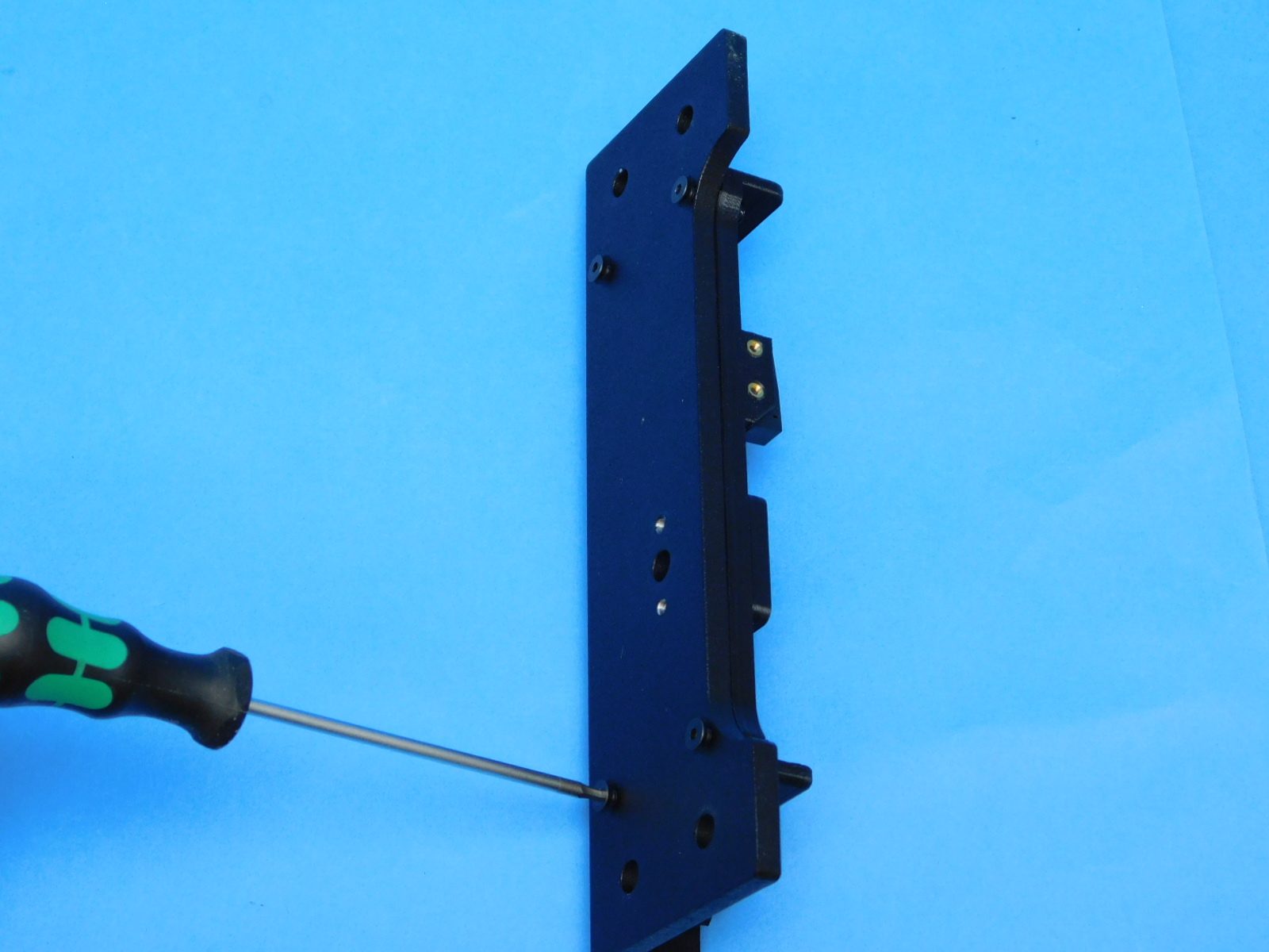
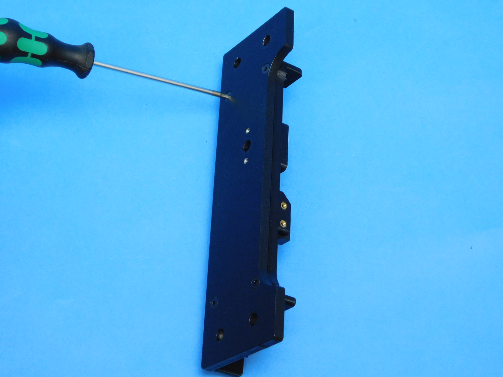
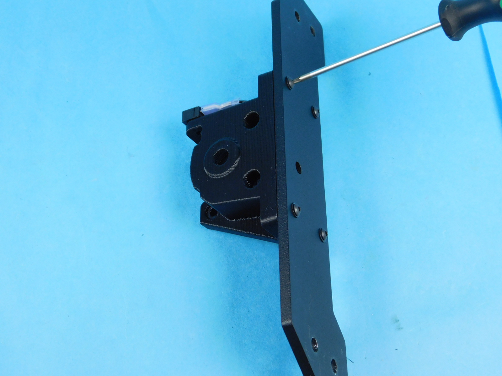
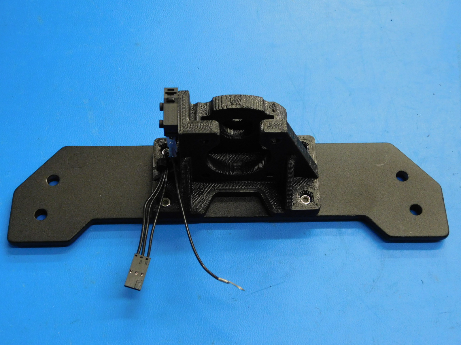
Secure the Y-Motor Mount to the [PP-FP0151] Y-Endplate using 4x [HD-BT0148] M3 x 10 Bolts with 4x [HD-WA0038] M3 Washers, and insert 4x [HD-NT0001]** Nyloc Locknuts into the printed part to attach the Y-Motor Mount to the Y-Endplate. Note the correct part orientation.
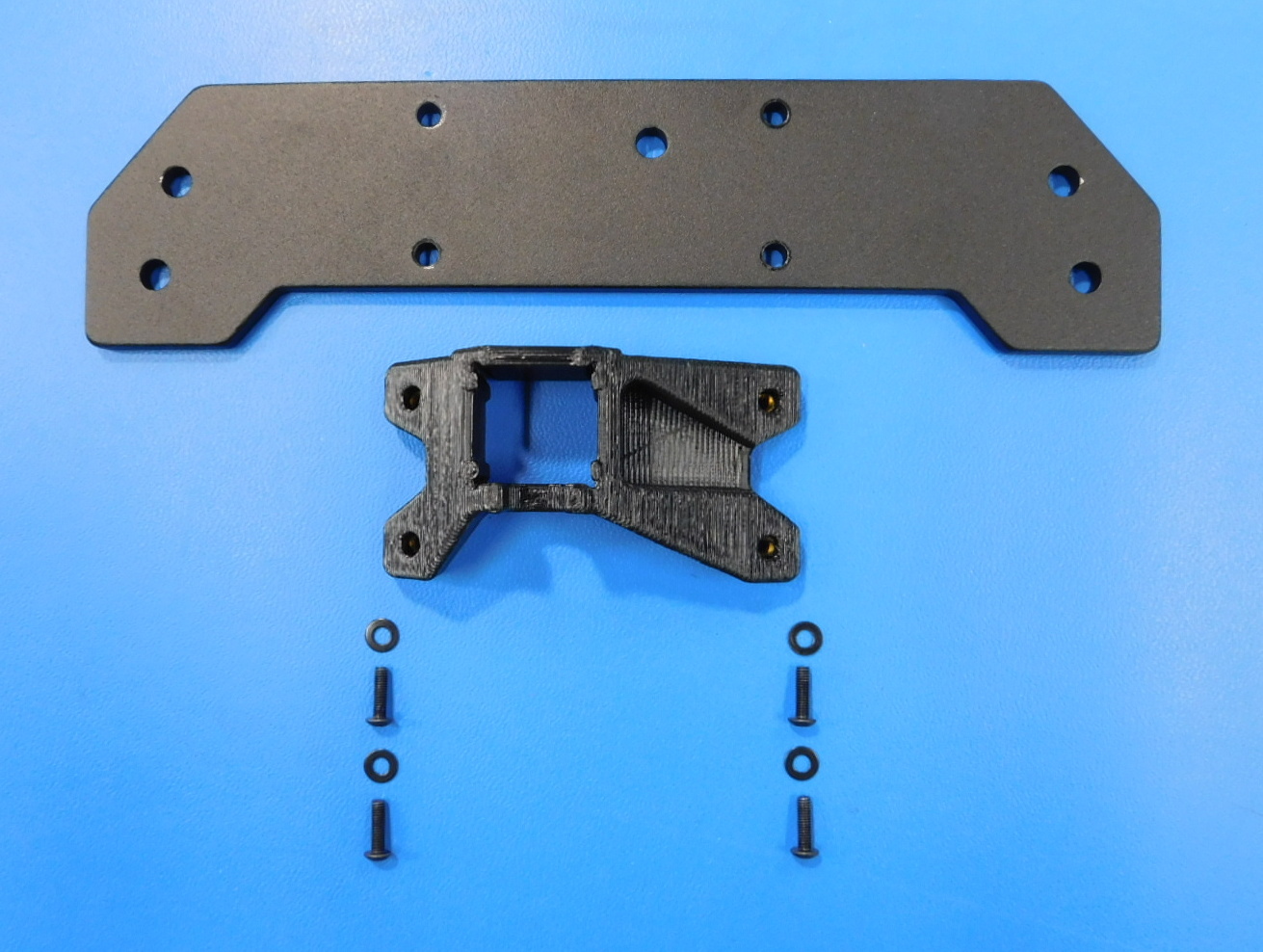
Materials required for [AS-PR0122] Y-Idler Mount Assembly:
1x - [PP-FP0151] Y Endplate
1x - [PP-IS0091] Y-Idler Housing with Inserts
4x - [HD-BT0148] M3 x 10 Button Head Screw
4x - [HD-WA0038] M3 Black-Oxide Flat Washer
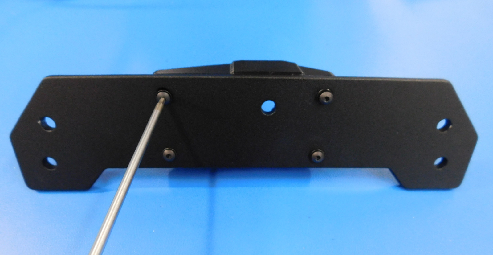
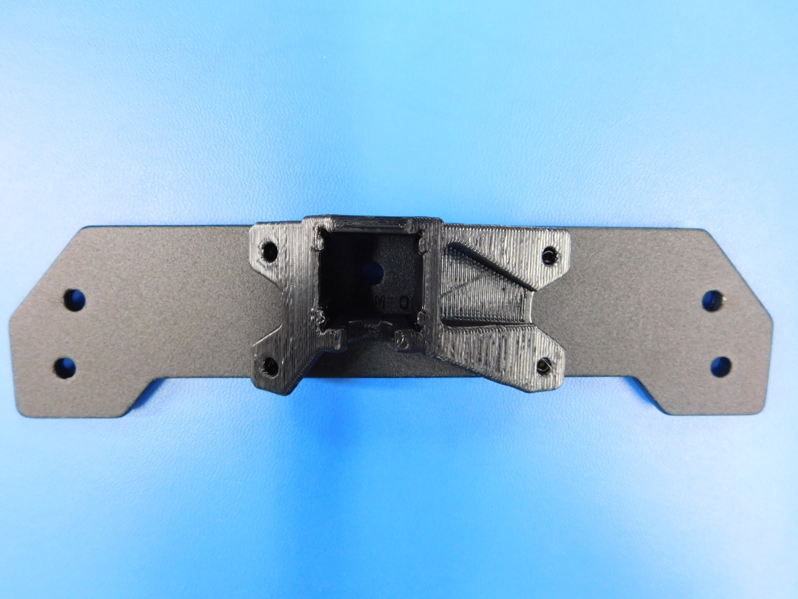
Secure the [PP-IS0091] Y-Idler Housing with Inserts to the [PP-FP0151] Y-Endplate using 4x [HD-BT0148] M3 x 10 Bolts with 4x [HD-WA0038] M3 Washers. Note the correct part orientation.
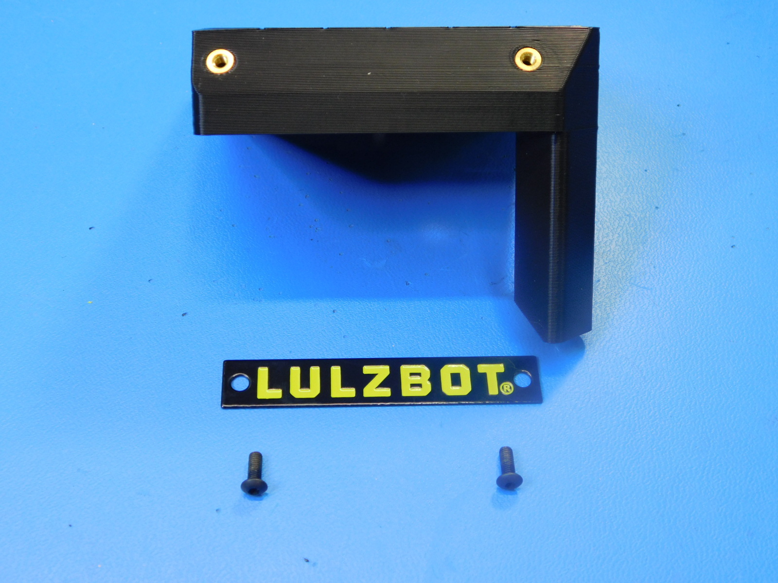
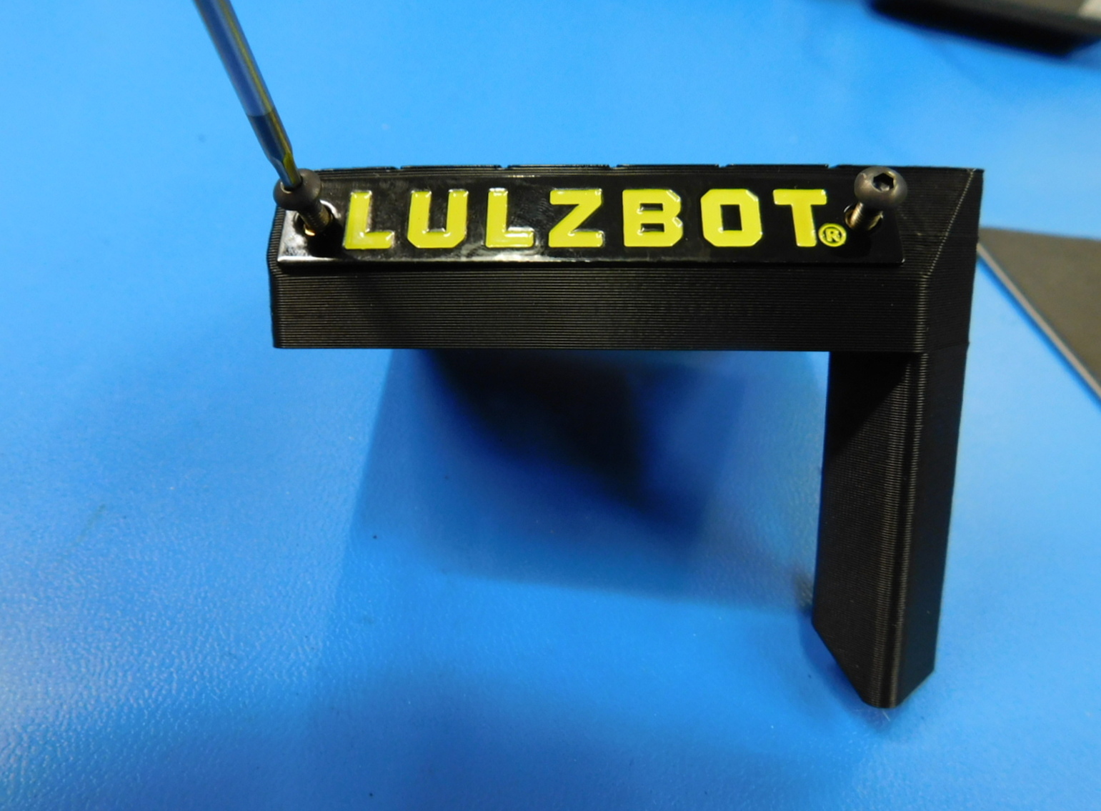
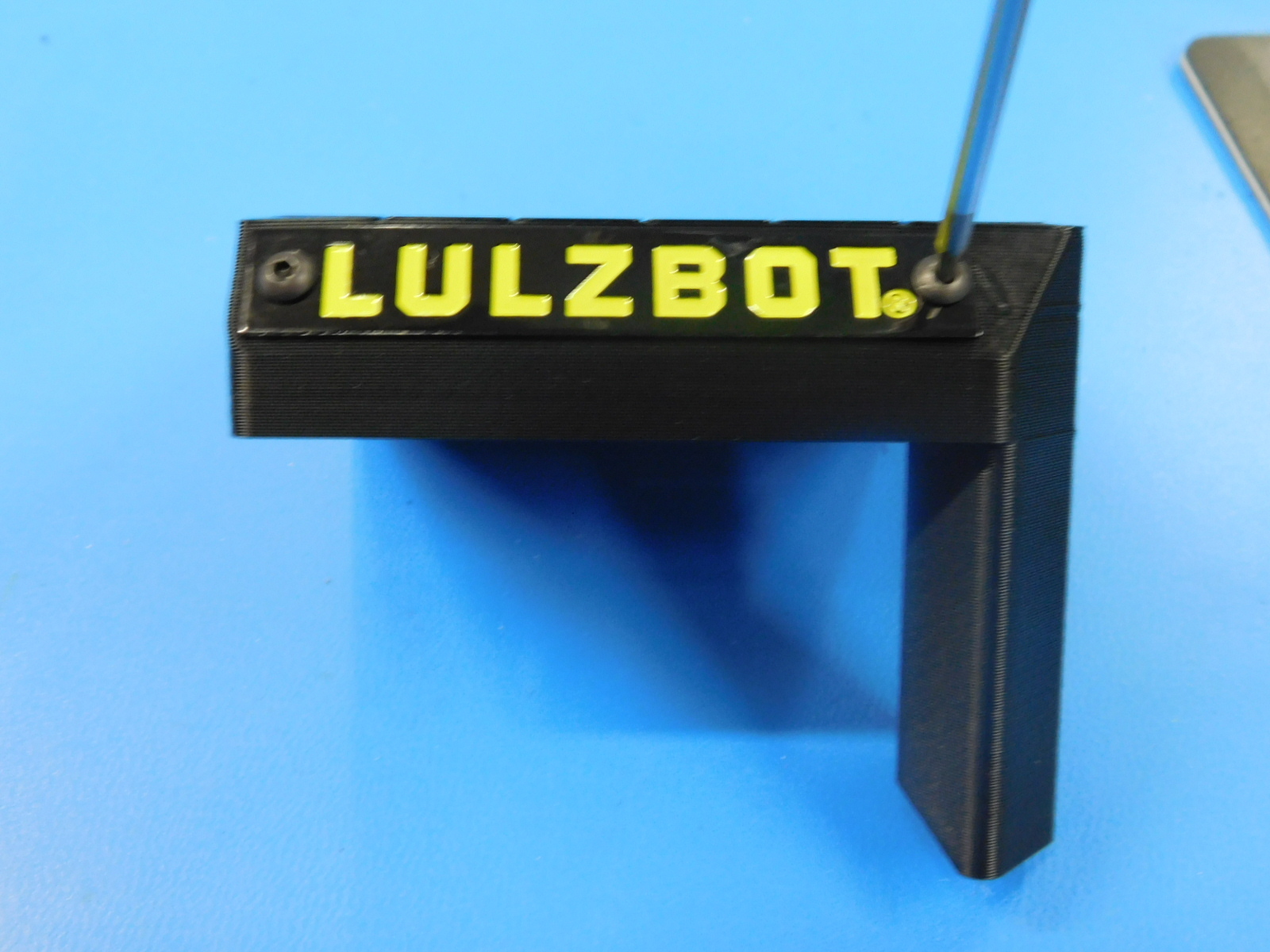
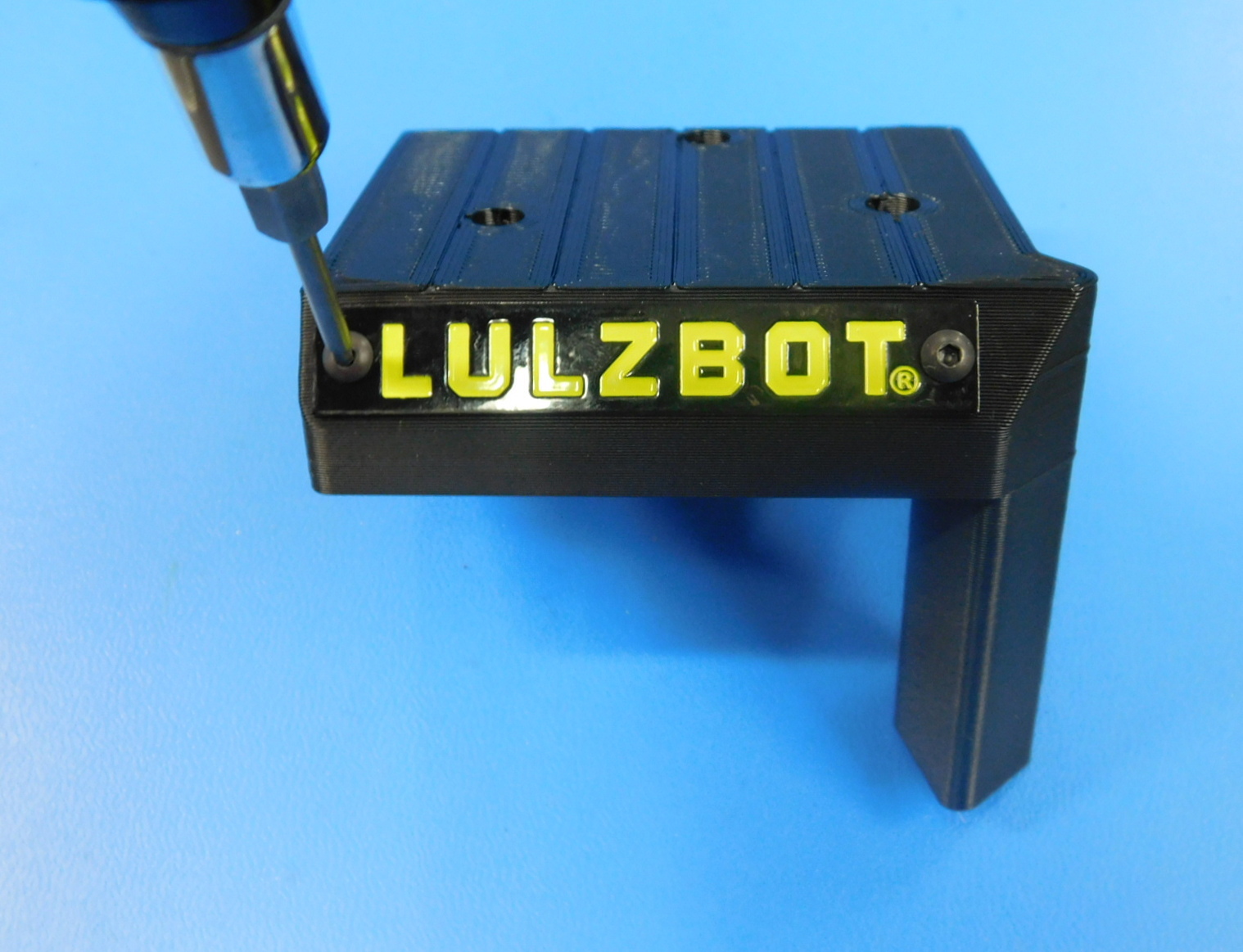
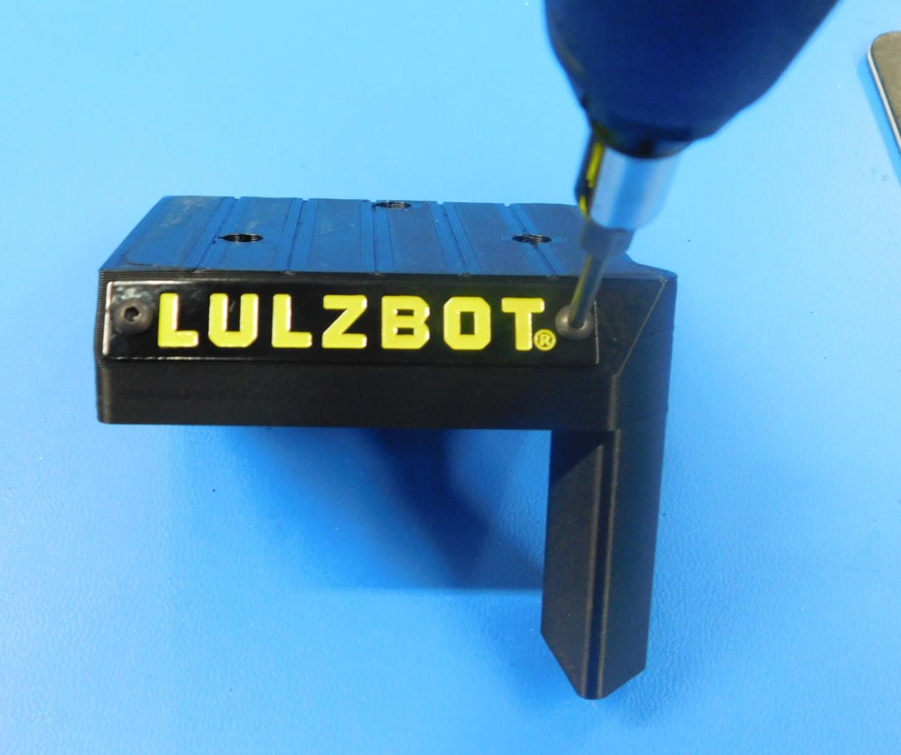
Materials required for [PP-IS0118] Extruder Cap with Plaque sub-assembly:
1x - [PP-GP0445] Extruder Cap (with Inserts installed)
1x - [DC-LB0186] LULZBOT Etched Toolhead Tag
2x - [HD-BT0137] M3 x 8 Bolt, BHCS, Black-Oxide
Secure the [DC-LB0186] LULZBOT Toolhead Tag to the [PP-GP0445] Extruder Cap with Inserts using 2 [HD-BT0137] M3 x 8 Bolts.
Torque to 3in*lbs
Note the correct orientation in the image shown.
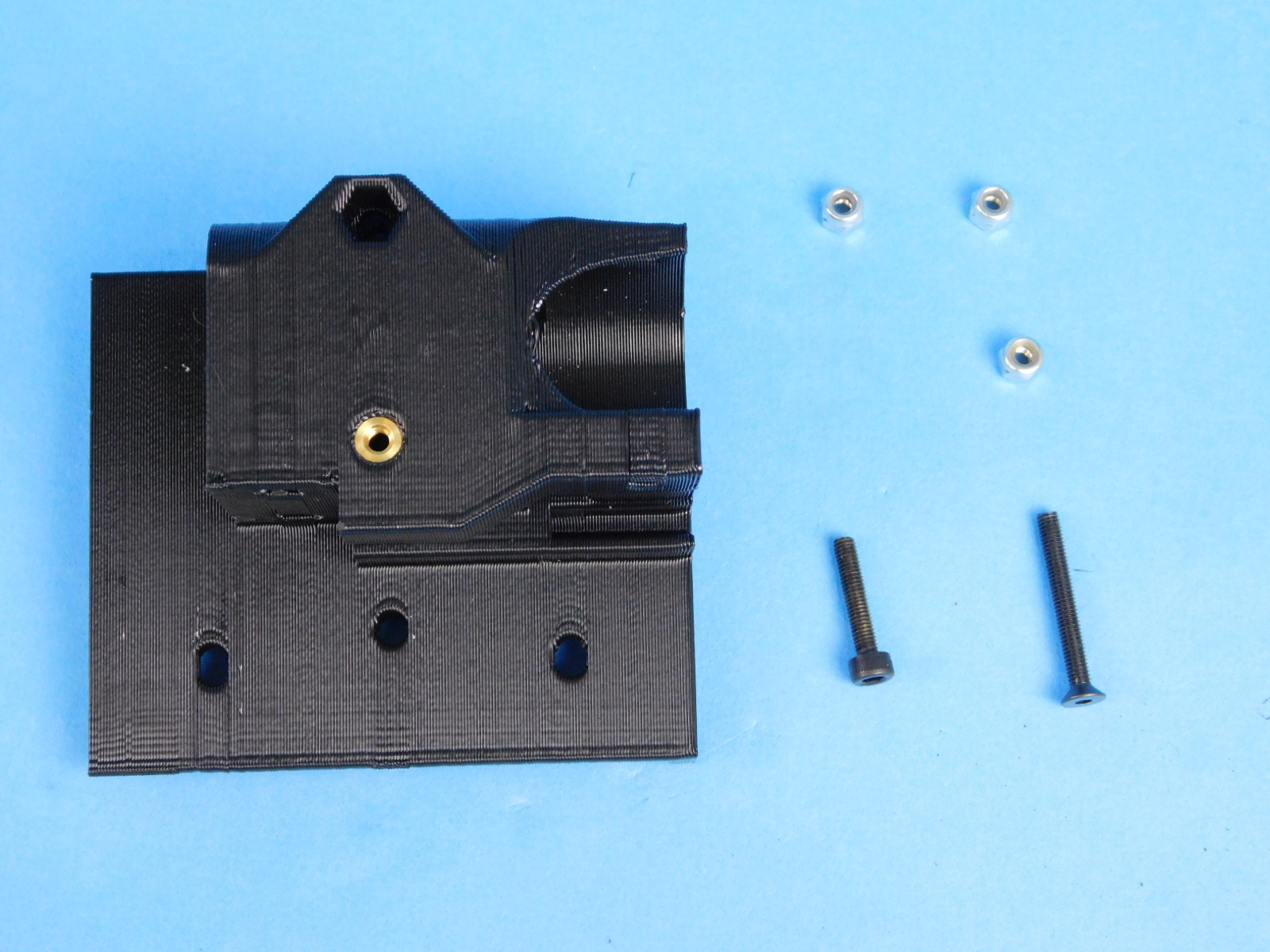
Materials required for AS-PR0158:
1x- [HD-BT0185] M3x16 SHCS, Black-Oxide
1x- [HD-BT0206] M3x25 FHCS, Black-Oxide
3x- [HD-NT0001] M3 Nyloc Nut
1x- [AS-PR0154] X-Carriage with bushing, redgum
See step 10 for X-Carriage Sub-Assembly [AS-PR0154] Insert Instructions
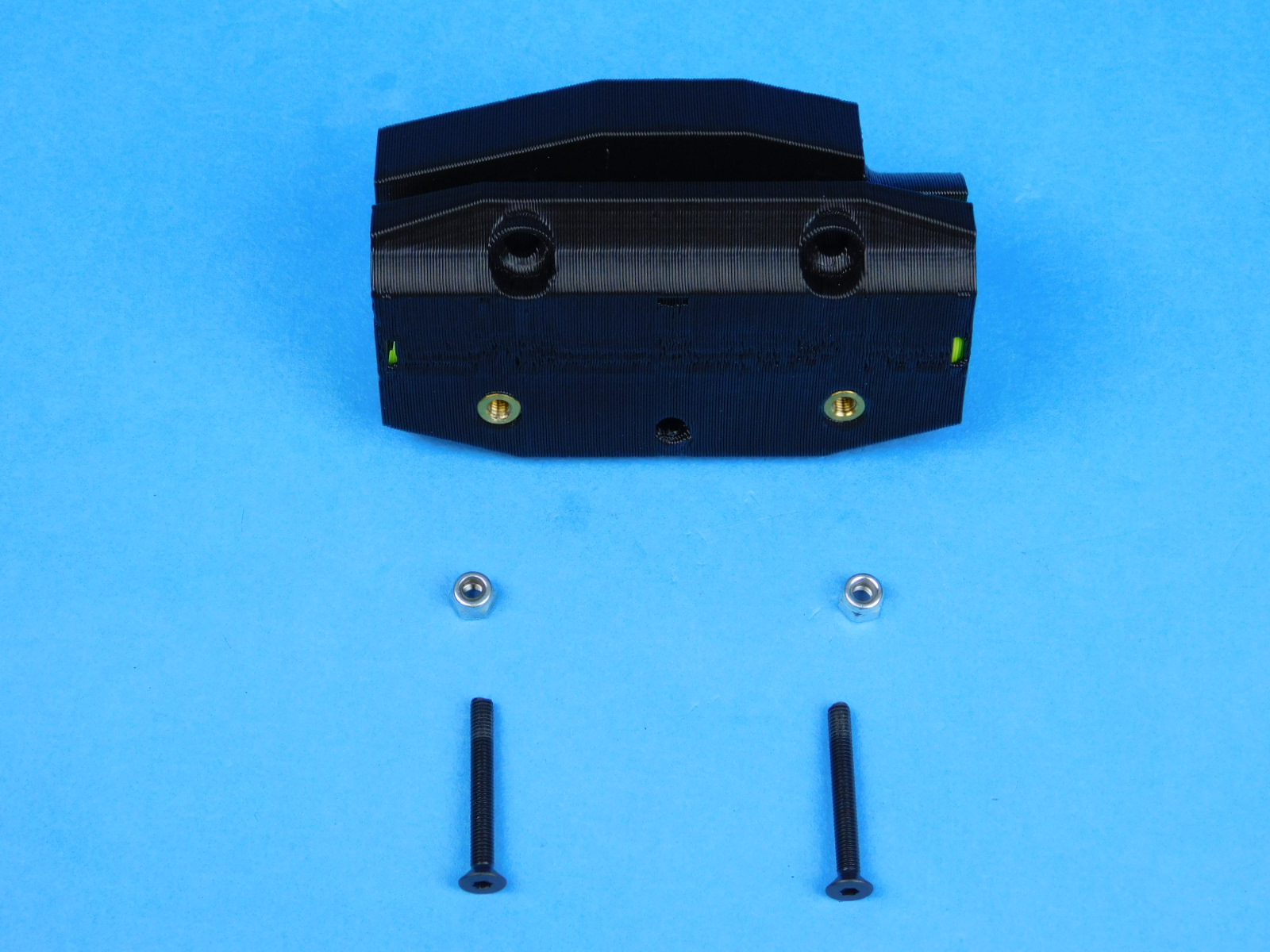
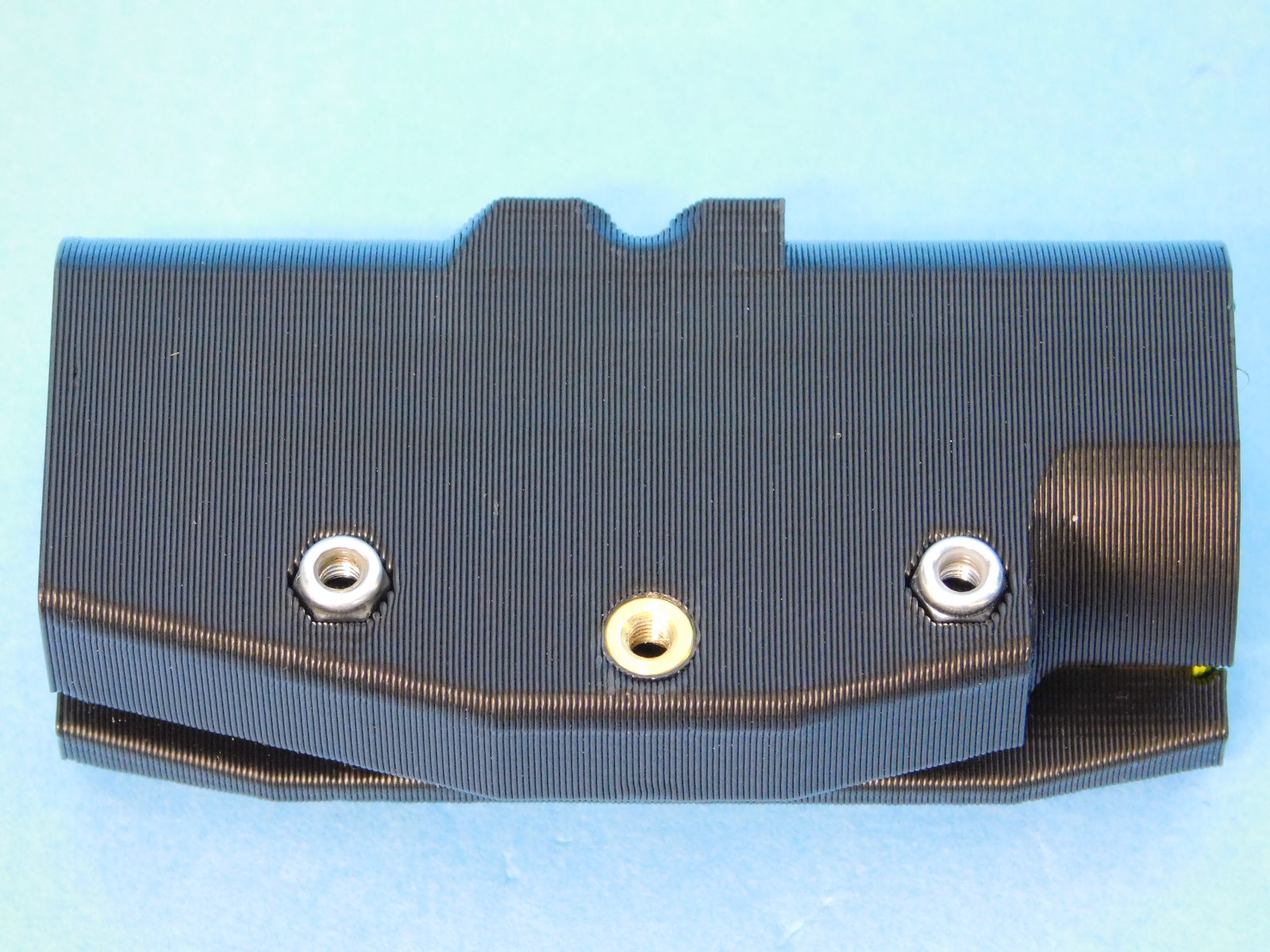
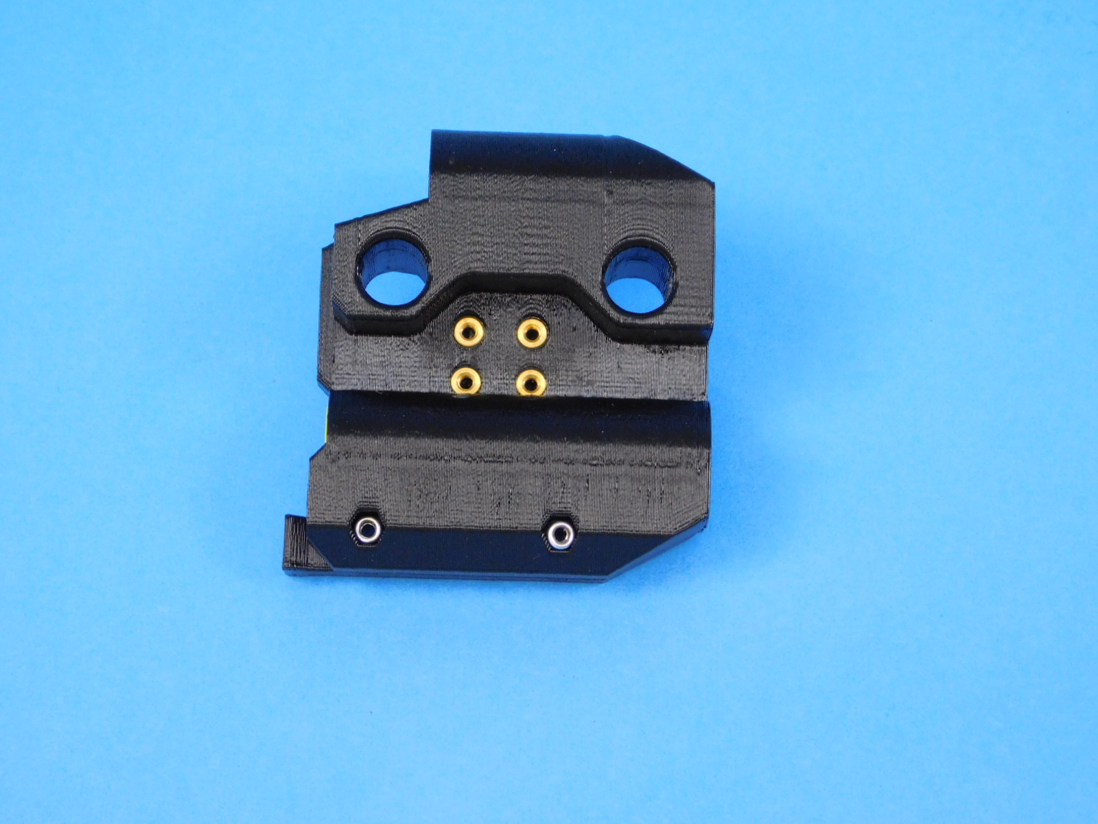
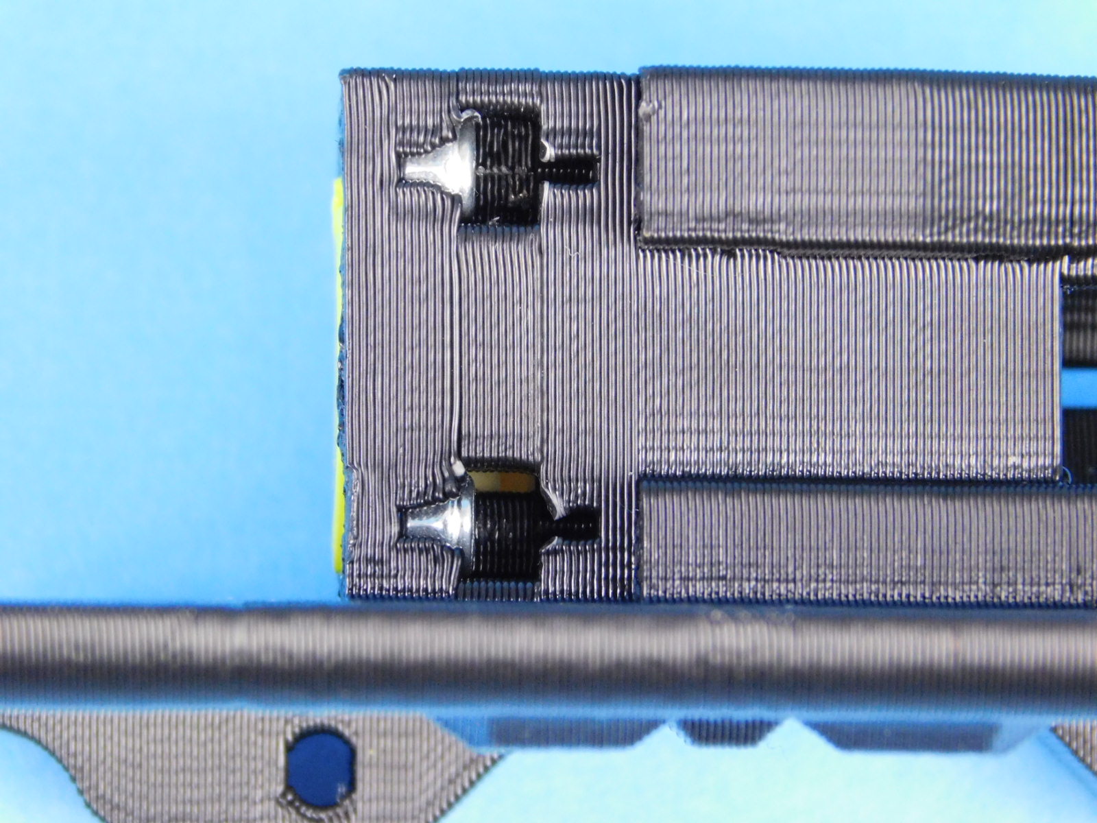
Place two M3 Nyloc Nuts [HD-NT0001] into the nut slots on the bottom of the X-Carriage with Bushing [AS-PR0154] as pictured. The nyloc side of the nut is facing photo right.
Place another M3 Nyloc Nut HD-NT0001] into the recess on the rear of the X-Carriage with Bushing [AS-PR0154]
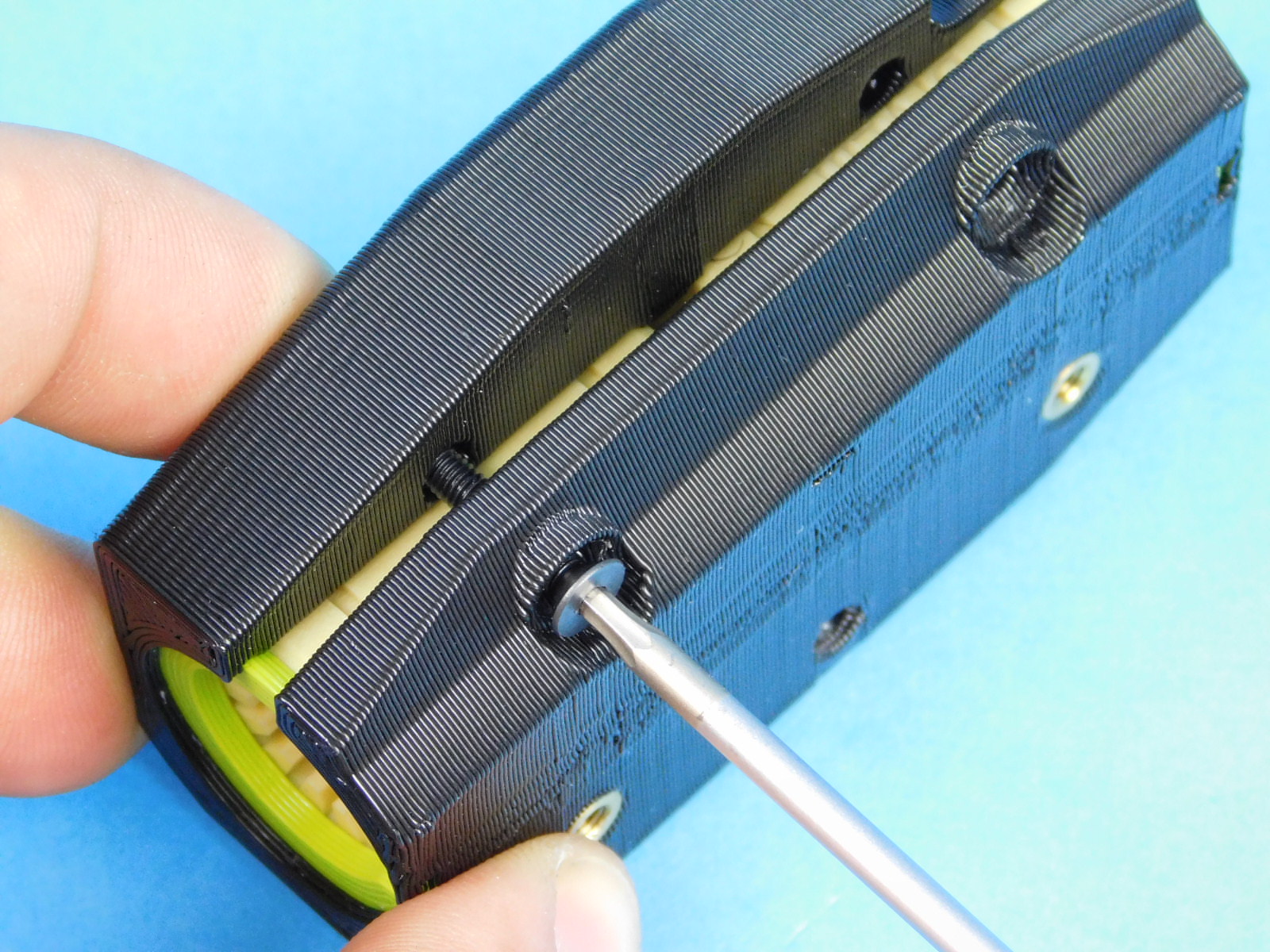
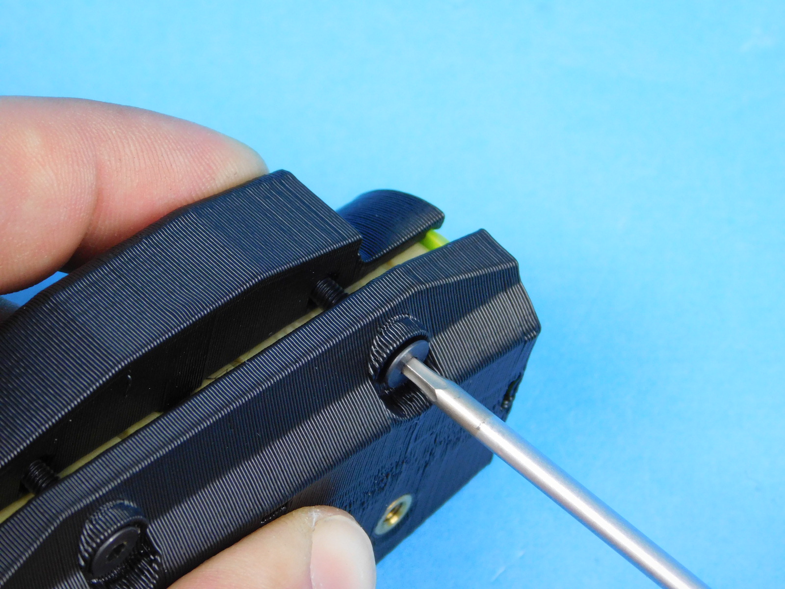
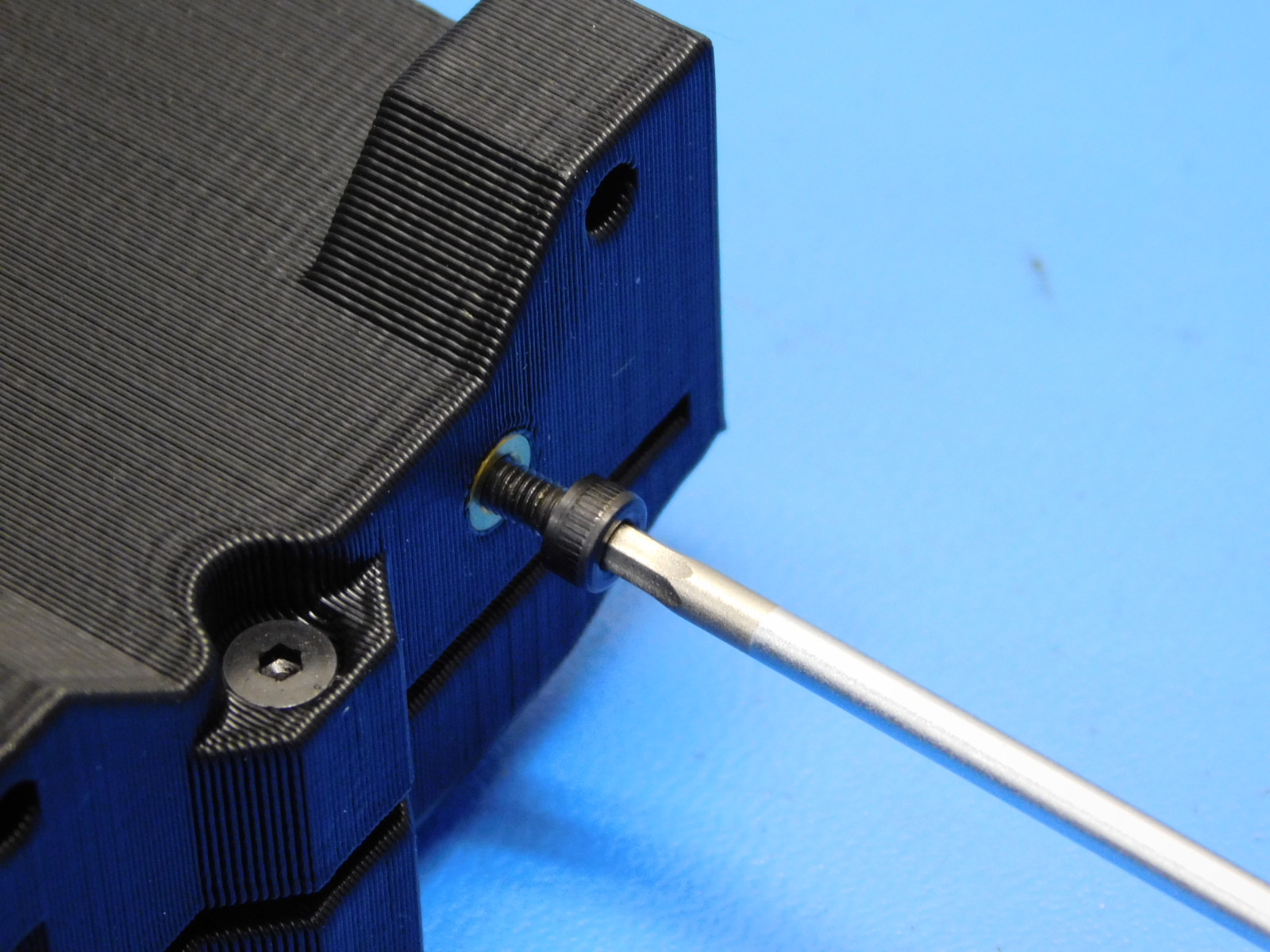
Thread one M3x25 FHCS [HD-BT0206] into that nut from the front side of the X-Carriage with Bushing [AS-PR0154] Do not tighten at this step.
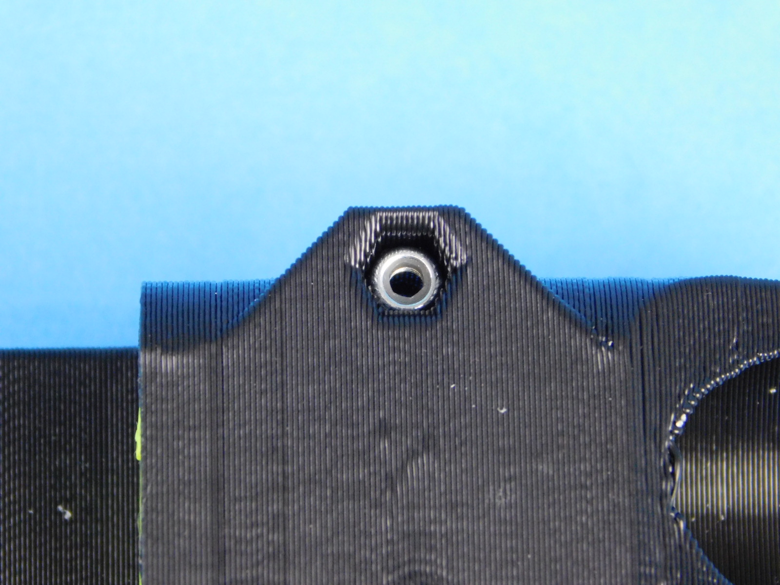
Install one M3x16 SHCS [HD-BT0185] into the top insert on the X-Carriage with Bushing [AS-PR0154]. No washer is needed, torque to 5in*lbs

Materials required for AS-PR0159:
2x- [HD-BT0206] M3x25 FHCS, Black-Oxide
2x- [HD-NT0001] M3 Nyloc Nut
1x- [AS-PR0155] X Double bearing holder with bushings
See step 11 for X-Double Bearing Holder [AS-PR0155] Insert Instructions
Install two M3 Nyloc Nuts [HD-NT0001] into the recesses on the rear of the X Double Bearing Holder w/ Bushings [AS-PR0155]
Install one M3x25 FHCS [HD-BT0206] into each nut from the front of the part. Use your fingers to hold the nyloc nuts in place while threading the fasteners into them.