Open HardwareAssembly Instructions
Guides for installation and assembly of the LulzBot line of products made by Aleph Objects, Inc.
Guides for installation and assembly of the LulzBot line of products made by Aleph Objects, Inc.
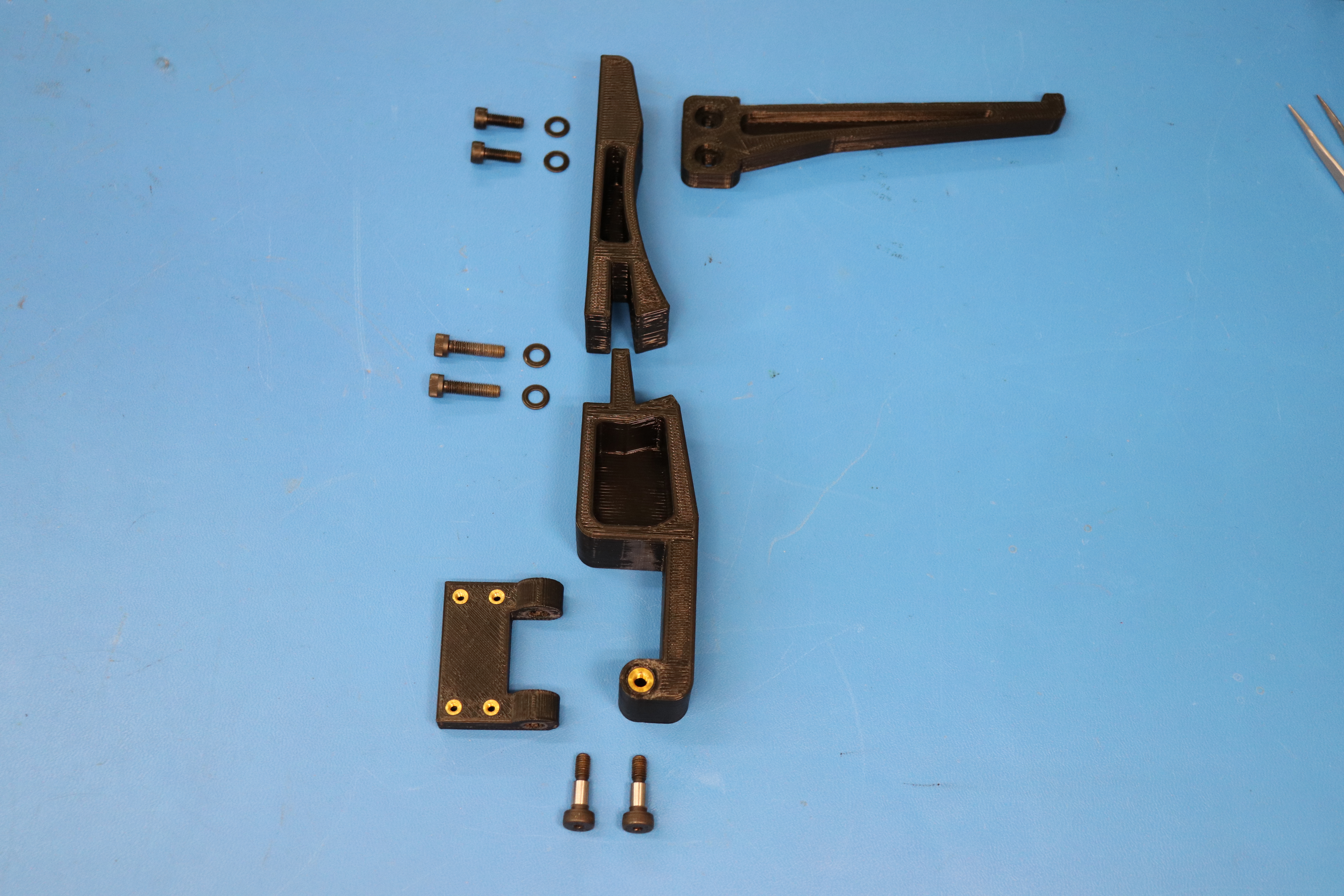
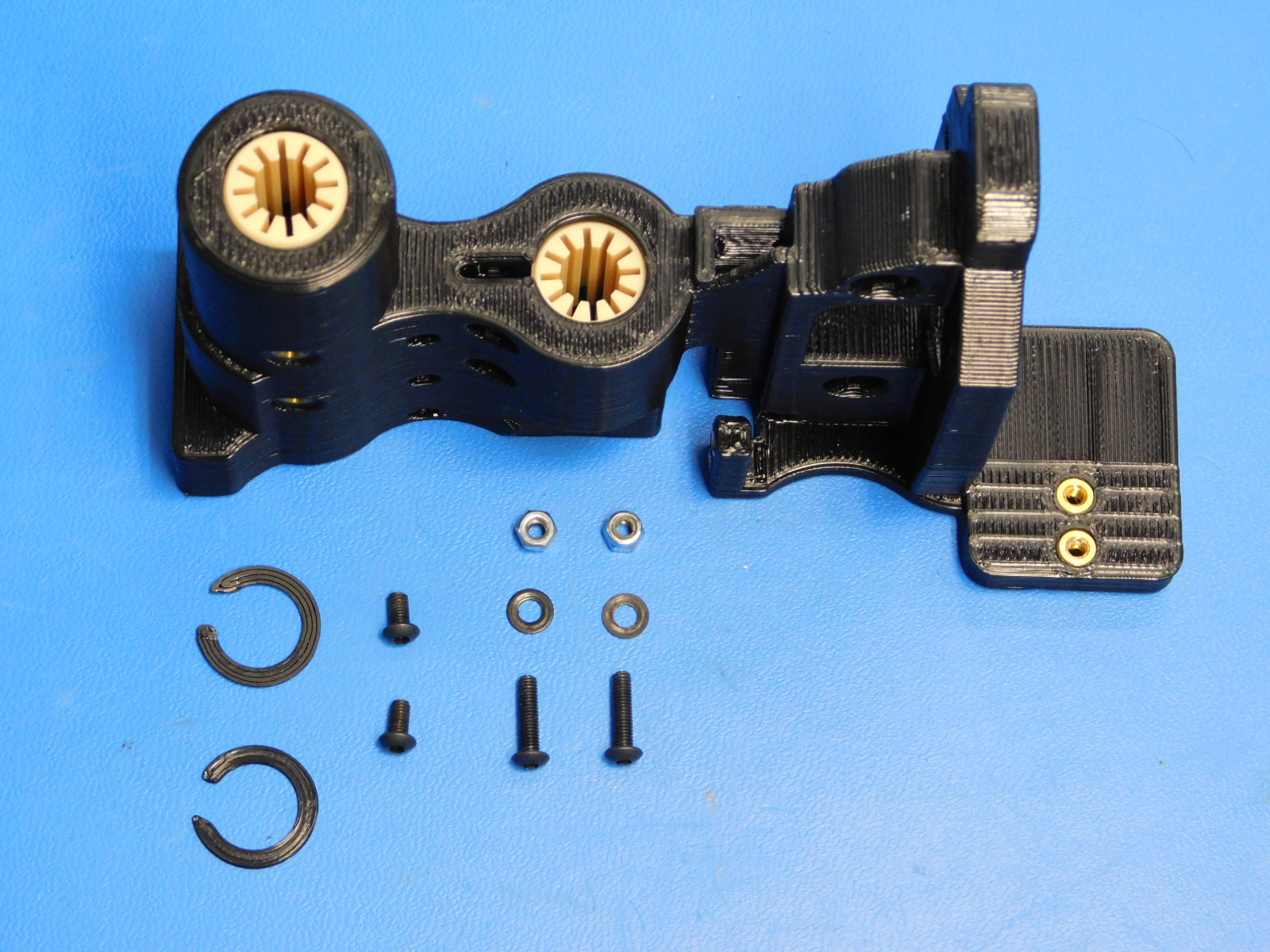
Materials Required for AS-PR0107:
1x- [PP-IS0067] Mini 2, Spool Hinge
1x- [PP-IS0044] Spool mount A with inserts
1x- [PP-IS0045] Spool Mount B with inserts
1x- [PP-GP0255] spool-arm_black_v1.4
2x- [HD-BT0049] Socket Head Cap Screw, Alloy Steel, M5 thread, 14MM length
2x- [HD-BT0120] Alloy Steel Shoulder Screw, 6mm Diameter x 10mm Long Shoulder, M5 Thread
4x- [HD-WA0040] Black-Oxide 18-8 Stainless Steel Flat Washer, M5 Screw Size, 5.3mm ID, 10.0mm OD
2x- [HD-BT0151] M5 x 20mm SCHS, Black Oxide
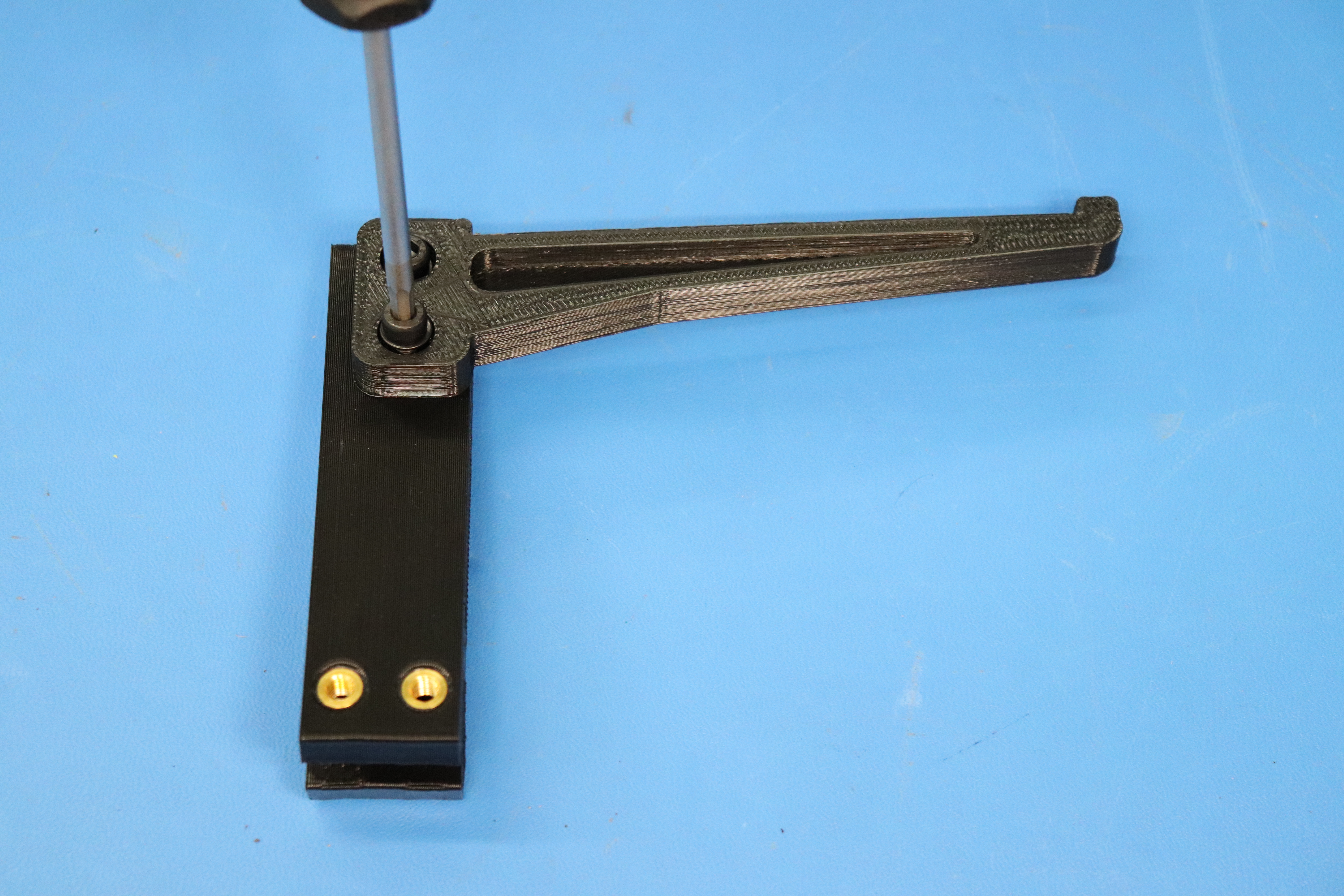
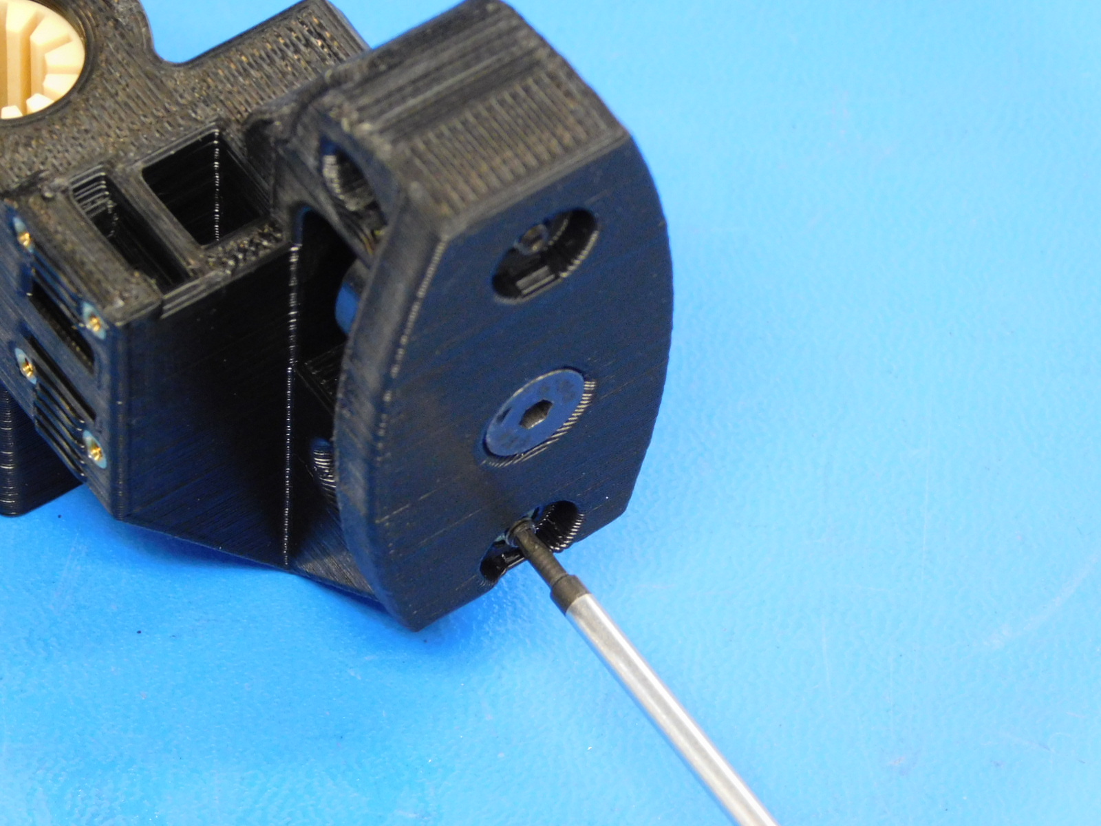
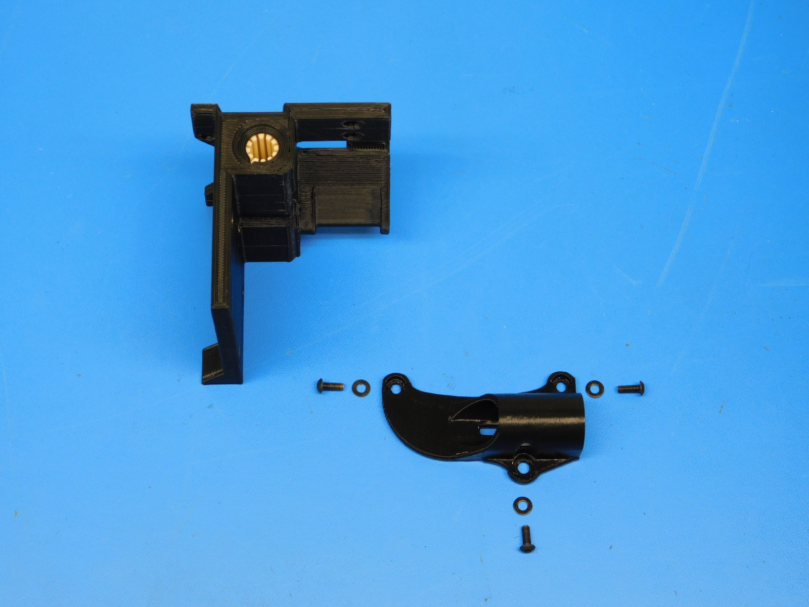
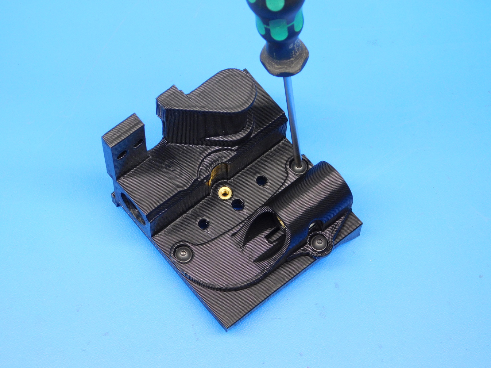
Use two M5x14mm SHCS [HD-BT0049] and two M5 washers [HD-WA0040] attach the spool arm [PP-GP0255] to the Spool Arm Mount B [PP-IS0045] with a 4 mm driver.
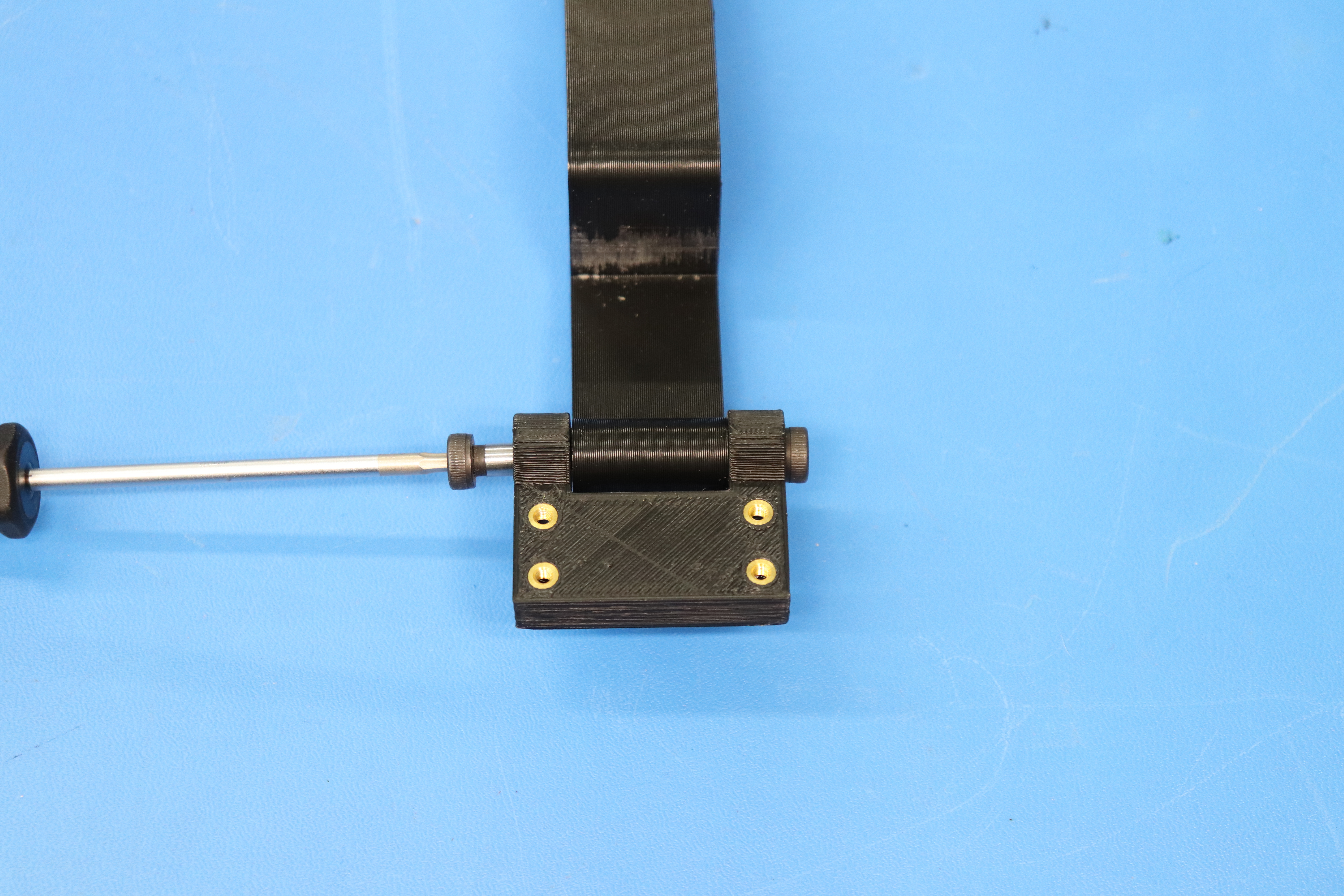
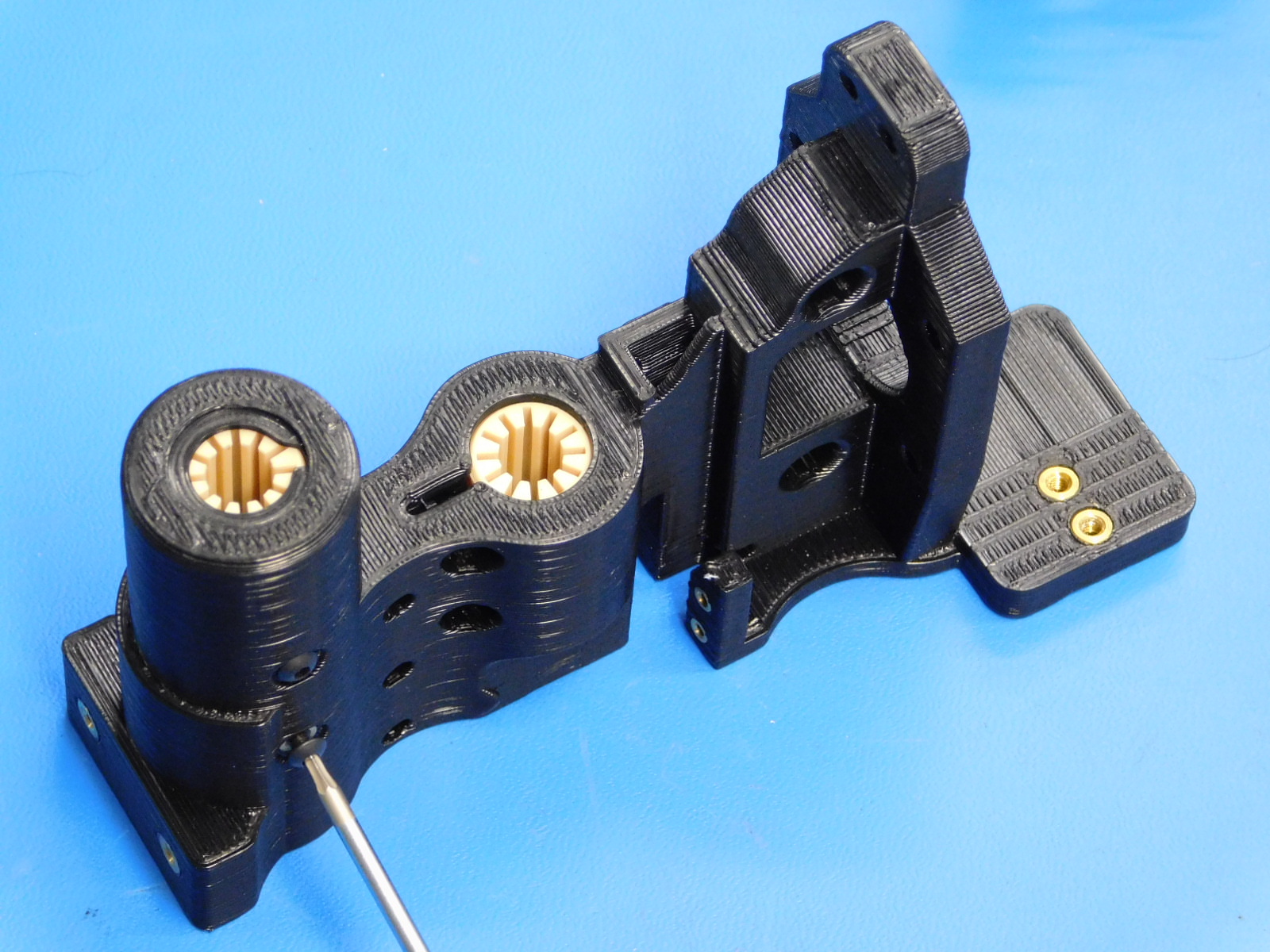
Then, use two M5 x 20 mm SHCS [HD-BT0151] with washers [HD-WA0040] to attach the Spool Arm Mount B to the Spool Arm Mount A [PP-IS0044].
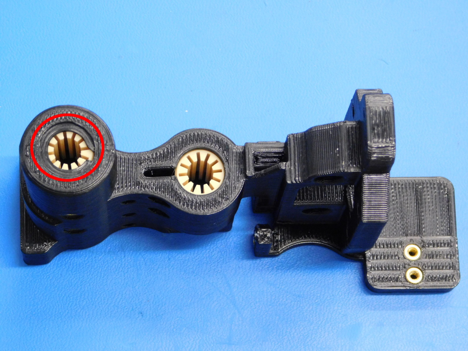
Finally, use two M5x20mm Shoulder Bolts [HD-BT0120] to attach the Spool Arm Assemblly to the spool hinge [AS-PR0062].

Materials Required to complete AS-PR0069:
1x- [PP-GP0264] y-idler-mini_black_v1.4 (with 4x- M3 Inserts [HD-MS0030] already installed)
1x- [HD-BT0117] Black Alloy Steel Flat-Head Socket Cap Screw, M8 Size, 40mm Length
2x- [HD-MS0282] 608-2RS ABEC3/C3 Rubber Sealed Bearing - BLACK
1x- [HD-NT0002] M8 Nyloc Nut, Zinc Plated
3x- [HD-WA0006] M8 Washer, Steel, Zinc Plated
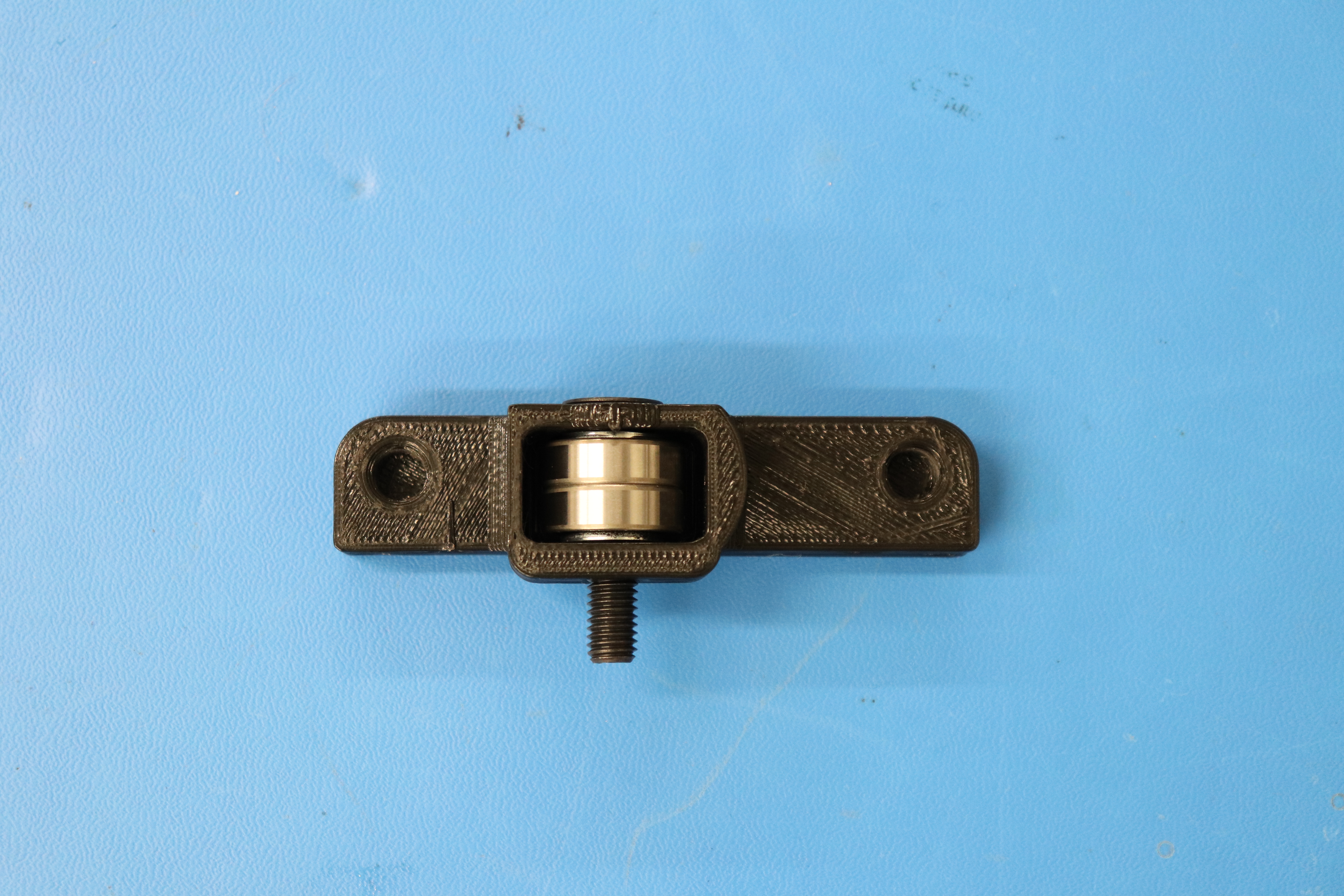
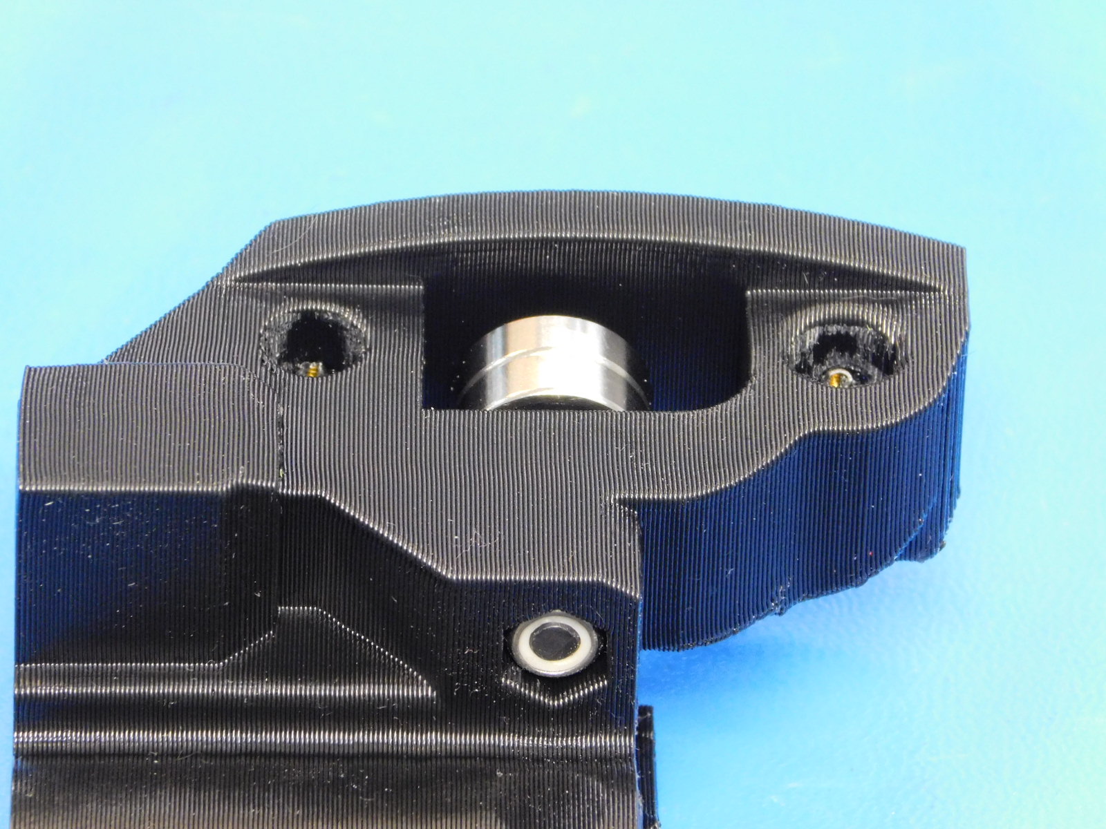
Drop two 608zz bearings [HD-MS0282] sandwiched between two M8 washers [HD-WA0006] into the recess in the printed part as shown.
Put a M8 x 40 mm FHCS [HD-BT0117] through the countersunk hole in the printed Y-Idler part [PP-GP0264].
Place an M8 Washer [HD-WA0006] and an M8 Nyloc Nut [HD-NT0001] on the end of the M8x40 Bolt.
Use a 5mm driver and a 13mm wrench to turn the nut onto the bolt.
Turn the bolt until the nut touches the washer and prevents up and down motion of the bolt in the printed part, but Do not tighten it.

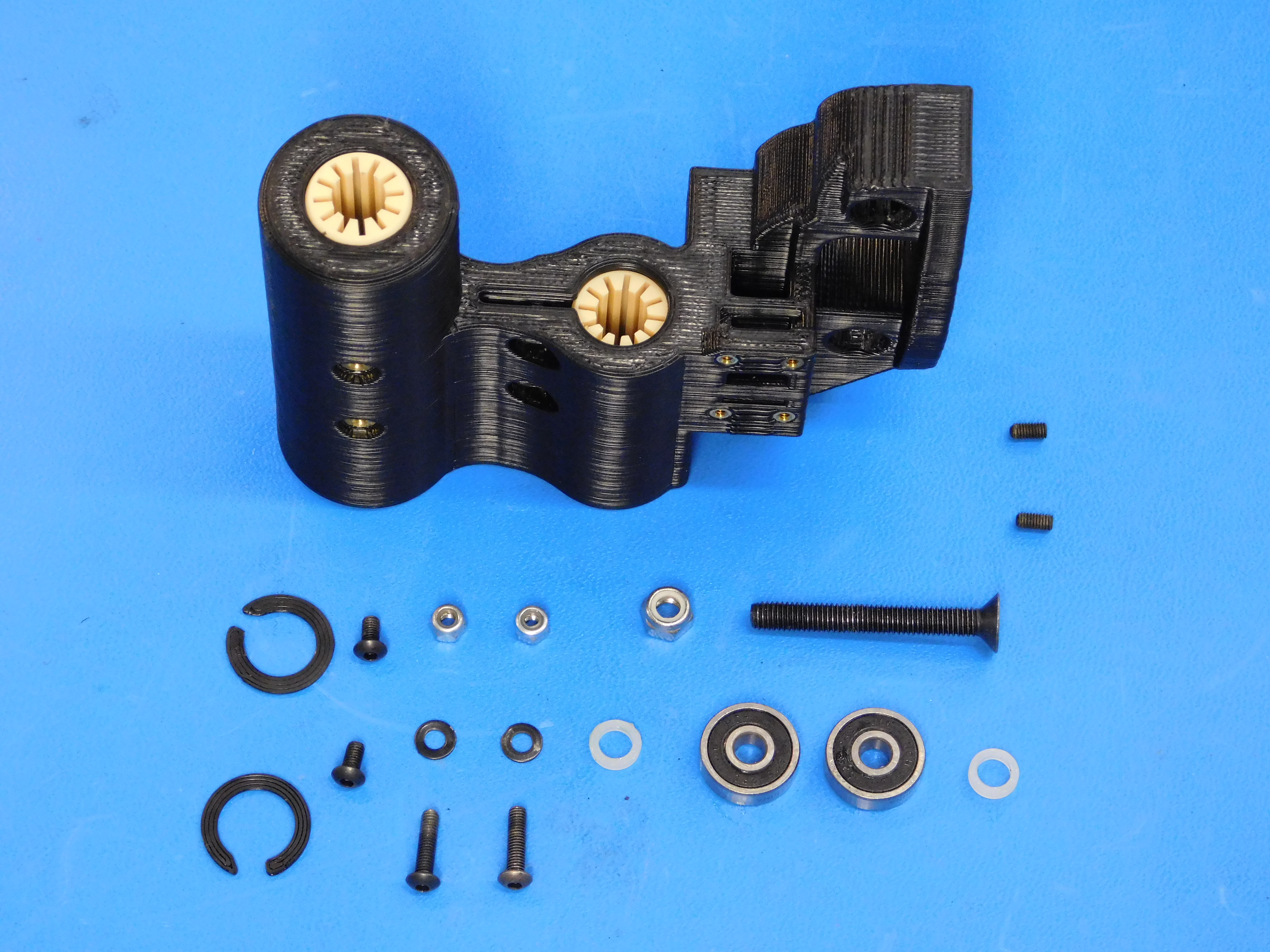
Materials Required for AS-PR0087:
1x- [AS-PR0095] X End Idler Assembly Mini 2 (with 4x M3 Inserts [HD-MS0030] & 4x M2 Inserts [PP-MP0066] already installed)
2x- [PP-GP0334] Retaining Ring
2x- [PP-GP0348] Printed threaded spacer
2x- [HD-BT0140] M3 x 6 Bolt, BHCS Black-Oxide
2x- [HD-BT0146] M3 x 12 BHCS, Black Oxide, Class 10.9 Steel
2x- [HD-MS0411] 625-2RS Premium Two Side Rubber Sealed Bearing ABEC3
2x- [HD-MS0427] Nylon Unthreaded Spacer 8 mm OD, 2 mm Length, for M5 Screw Size
1x- [HD-BT0216] Black-Oxide Alloy Steel Hex Drive Flat Head Screw M5 x 0.8 mm Thread, 40 mm Long
1x- [HD-NT0057] 18-8 Stainless Steel Nylon-Insert Locknut M5 x 0.8 mm Thread
2x- [HD-NT0001] Metric Zinc-Plated Steel Nylon-Insert Locknut, Class 8, M3 Screw sz, .5MM pitch, 5.5MM W, 4MM H
2x- [HD-WA0038] Black-Oxide 18-8 Steel Flat Washer, M3 Screw Size, 3.2mm ID, 7.0mm OD
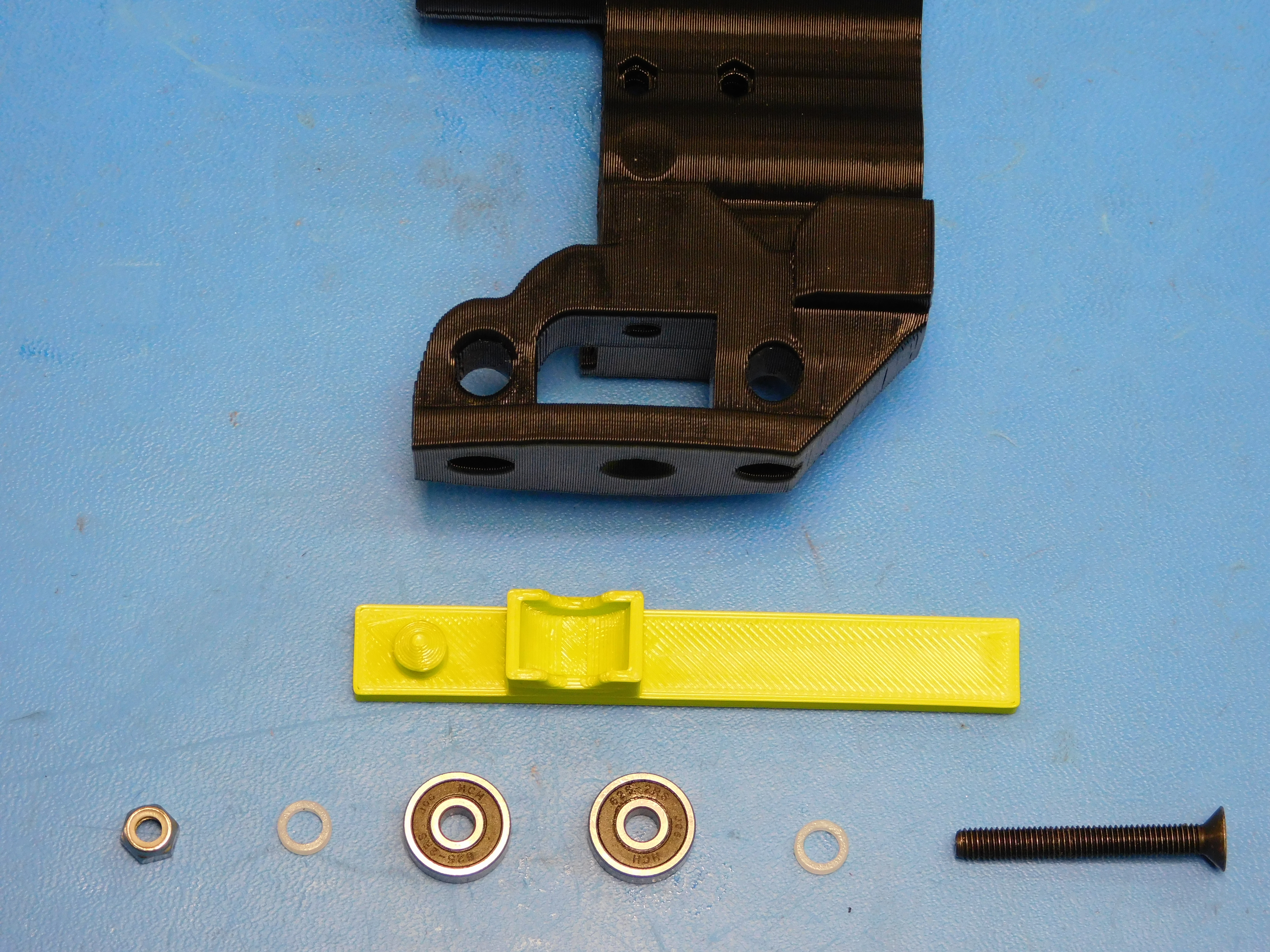
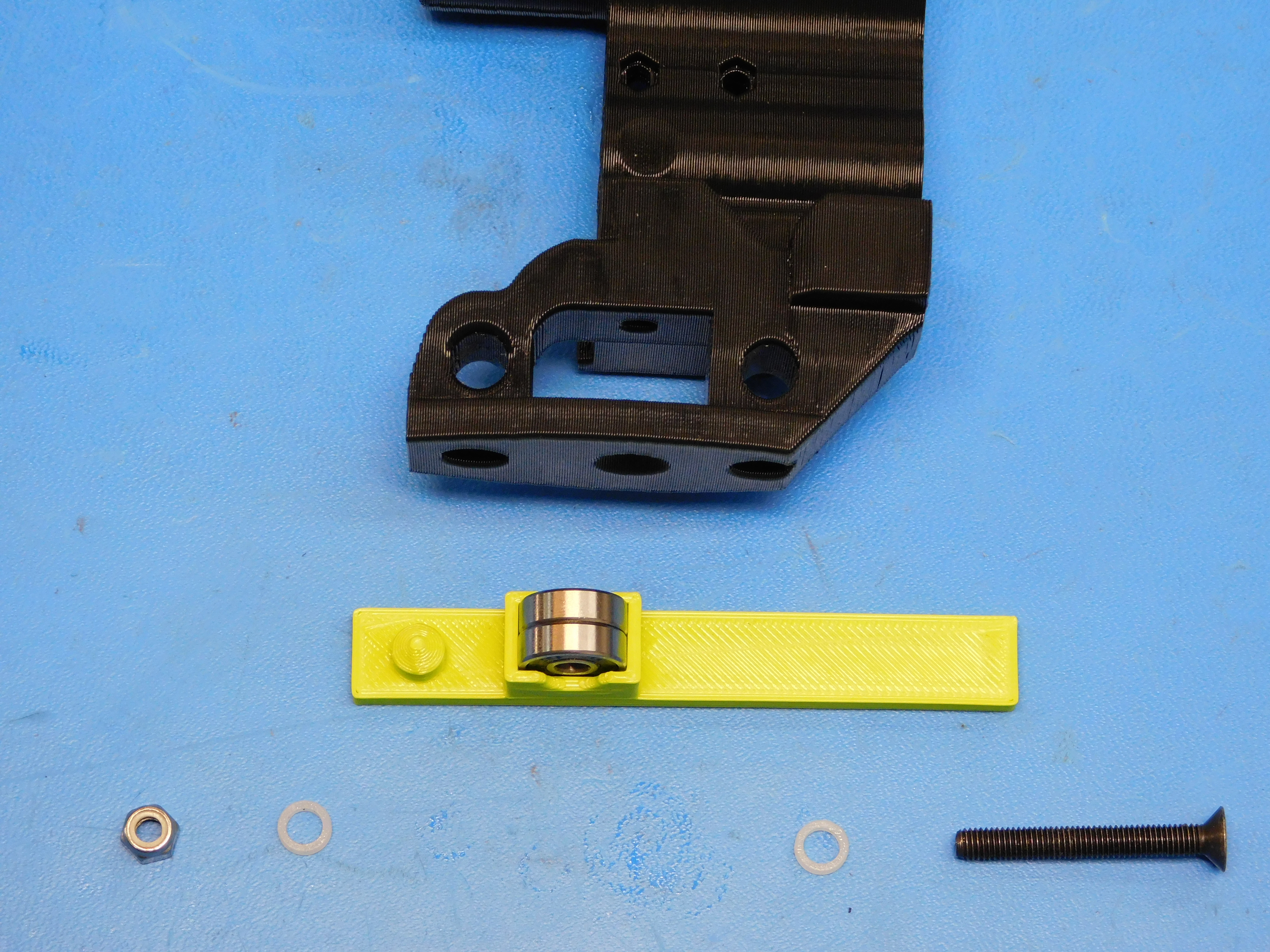
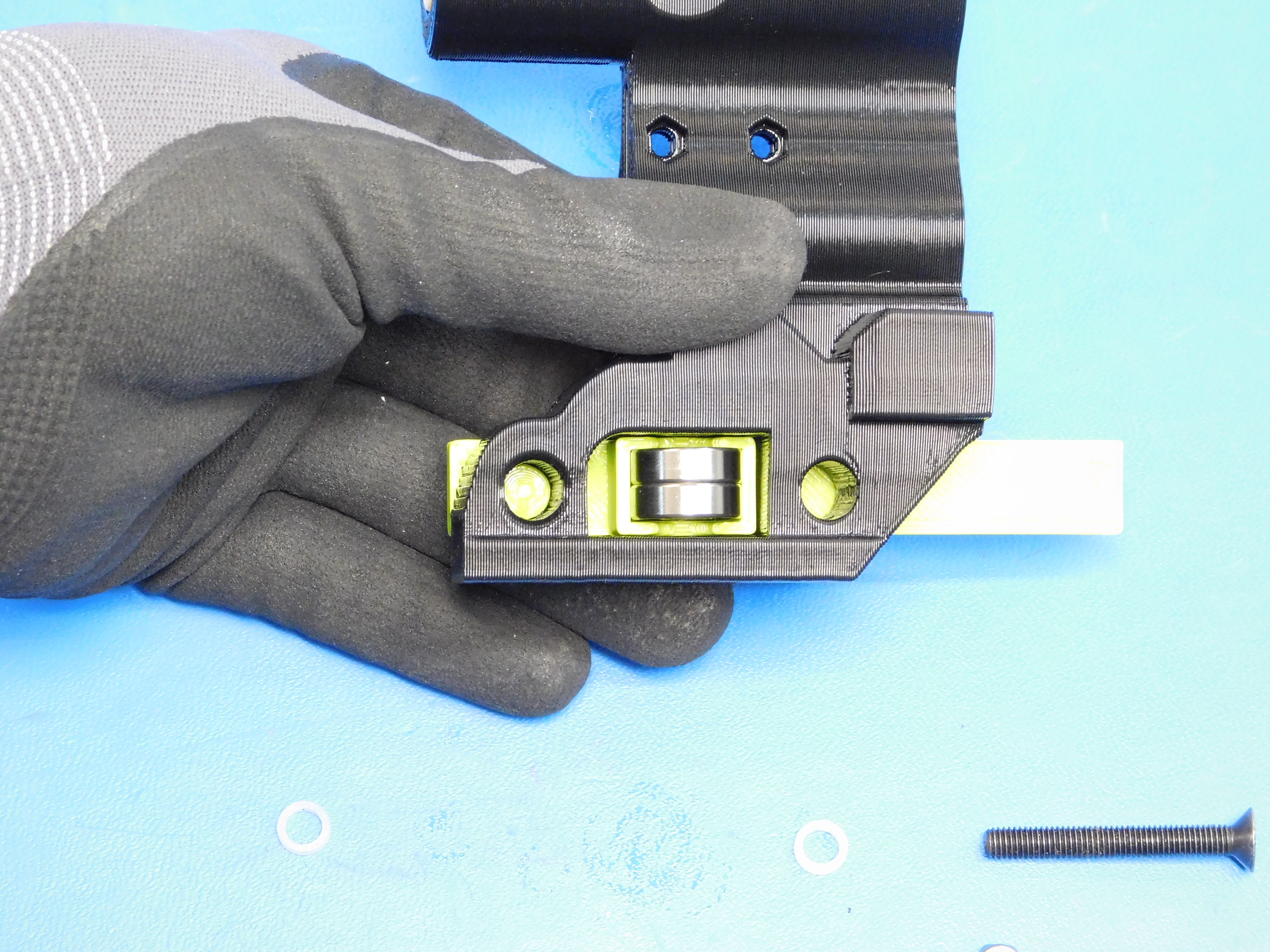
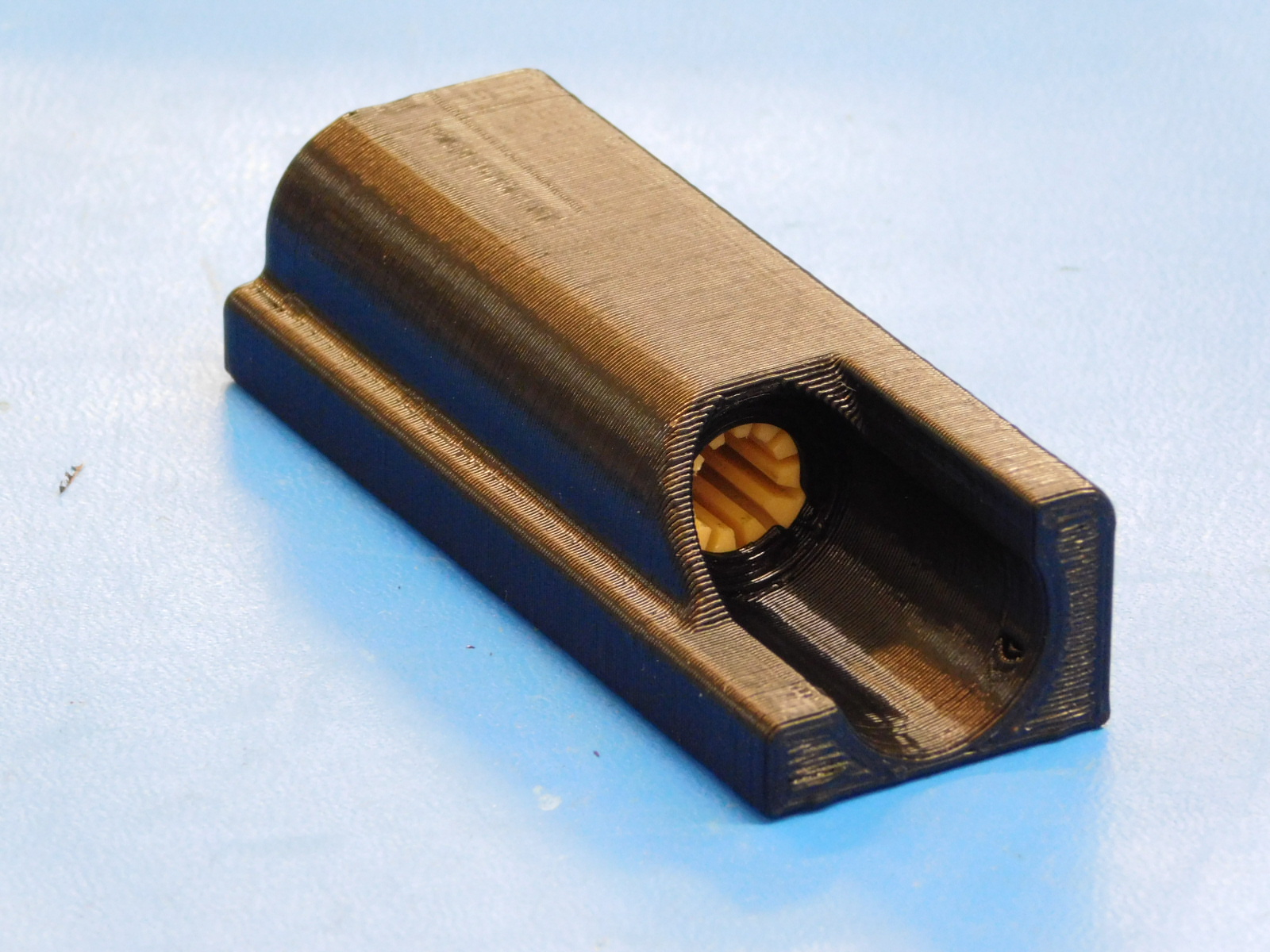
Using the X-Idler Bearing Helper Jig, place two 625-2RS bearings [HD-MS0411] into the printed jig as shown.
Fit the printed jig into the X-End Idler printed part as shown.
Drop a spacer [HD-MS0427] on each side of the bearings, resting on the printed jig shown.
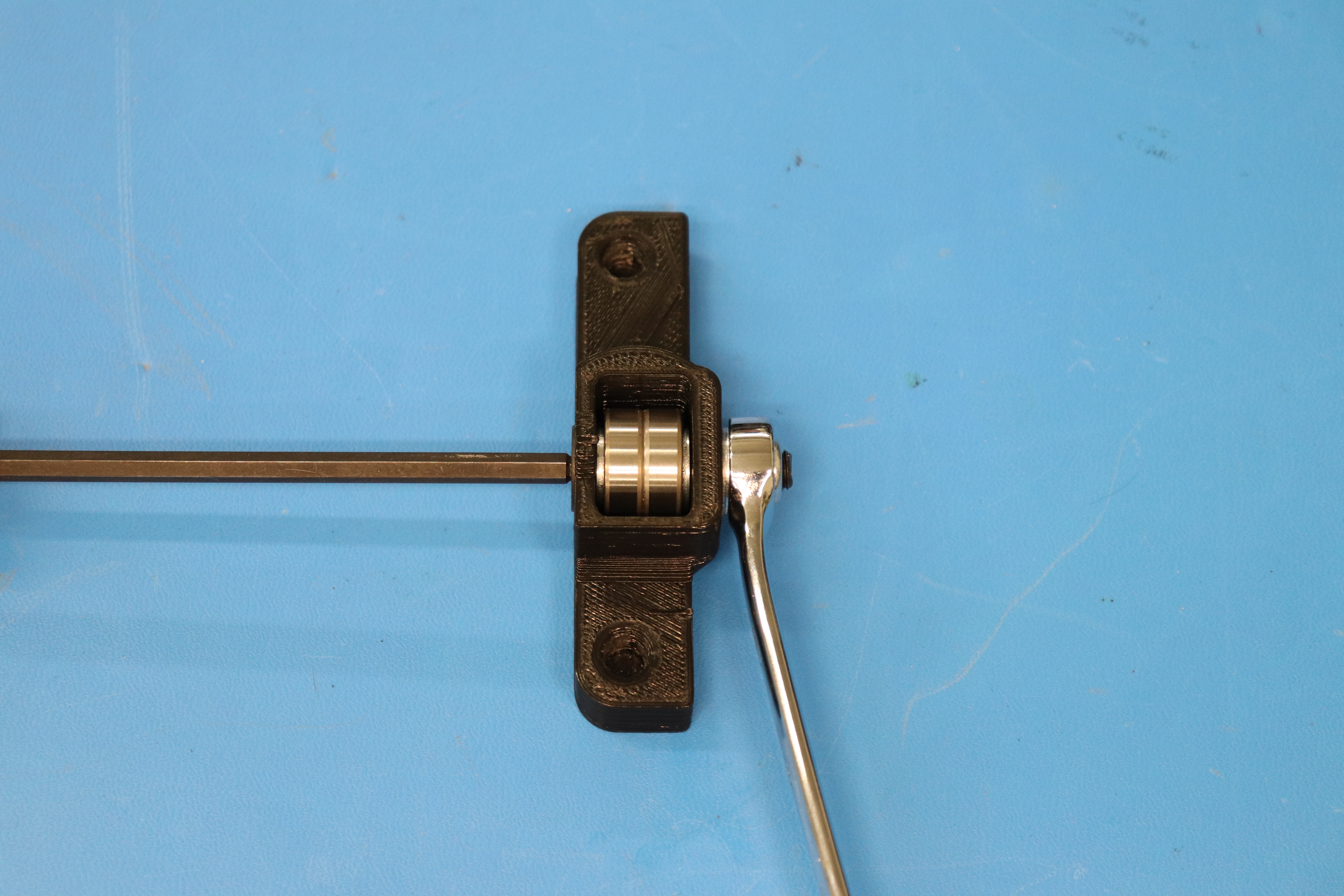
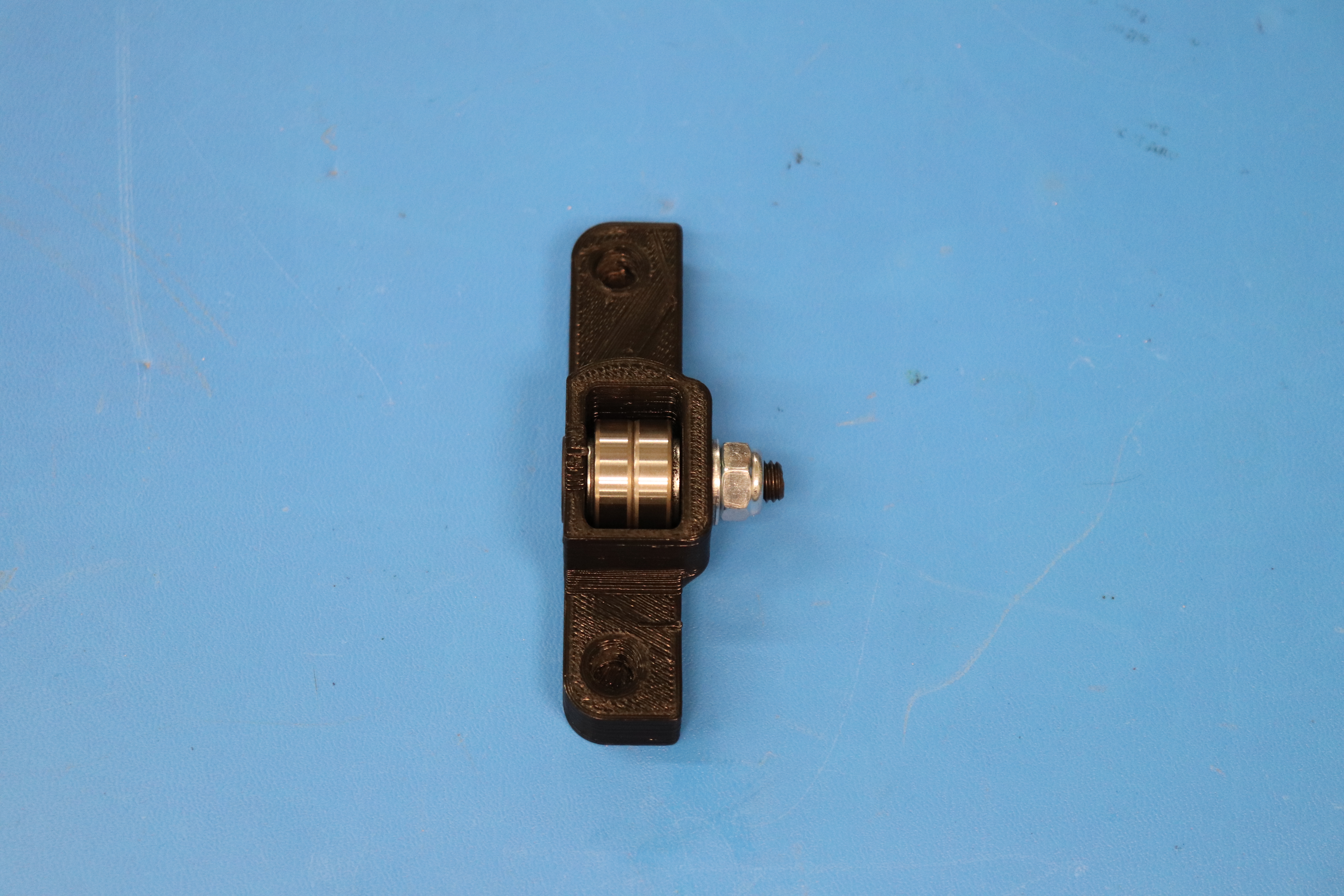
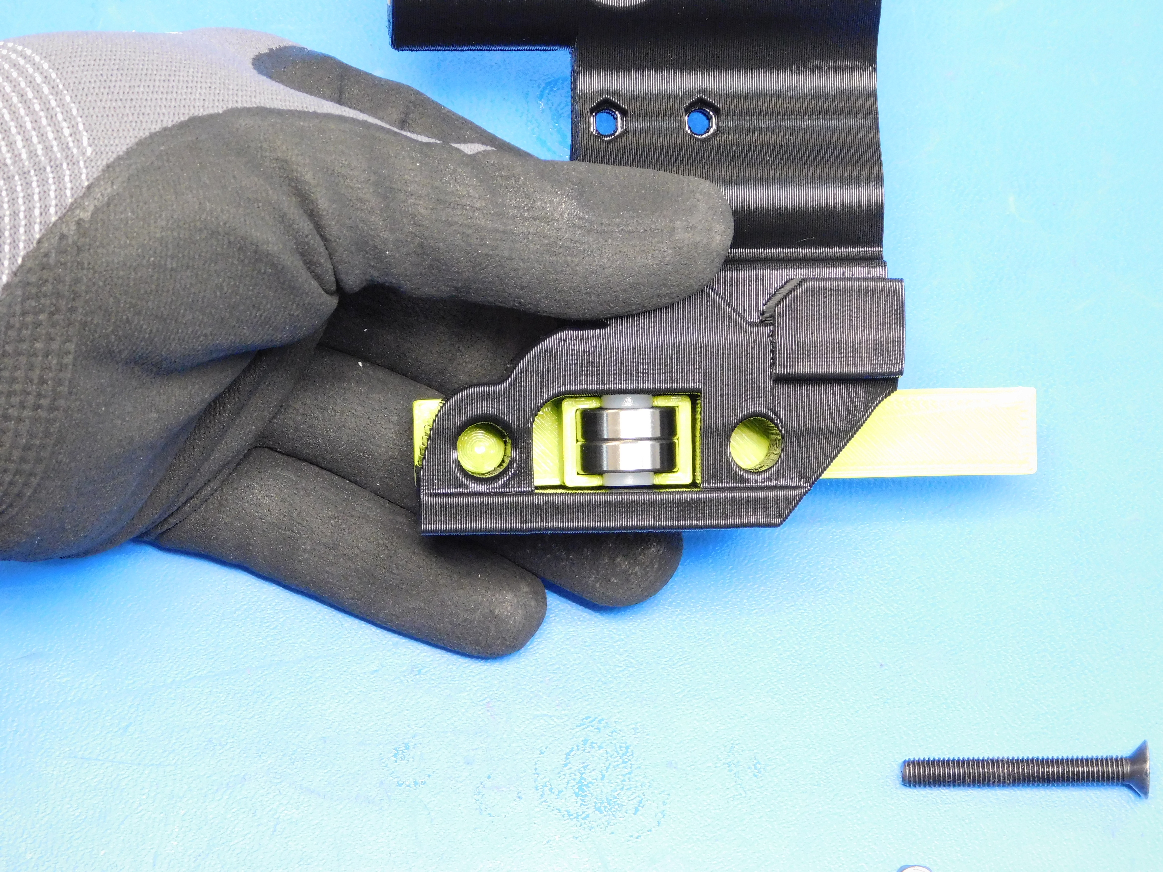
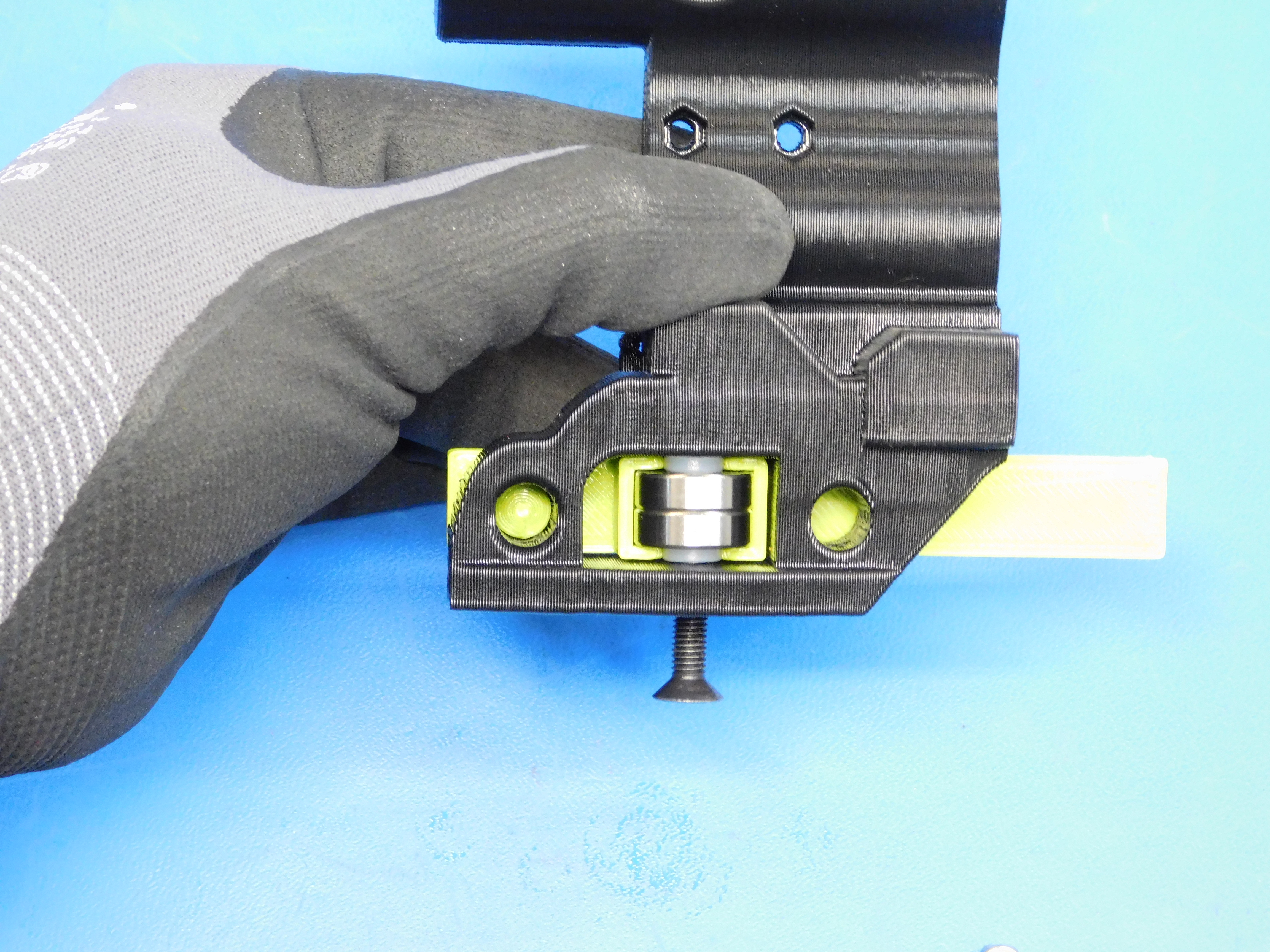
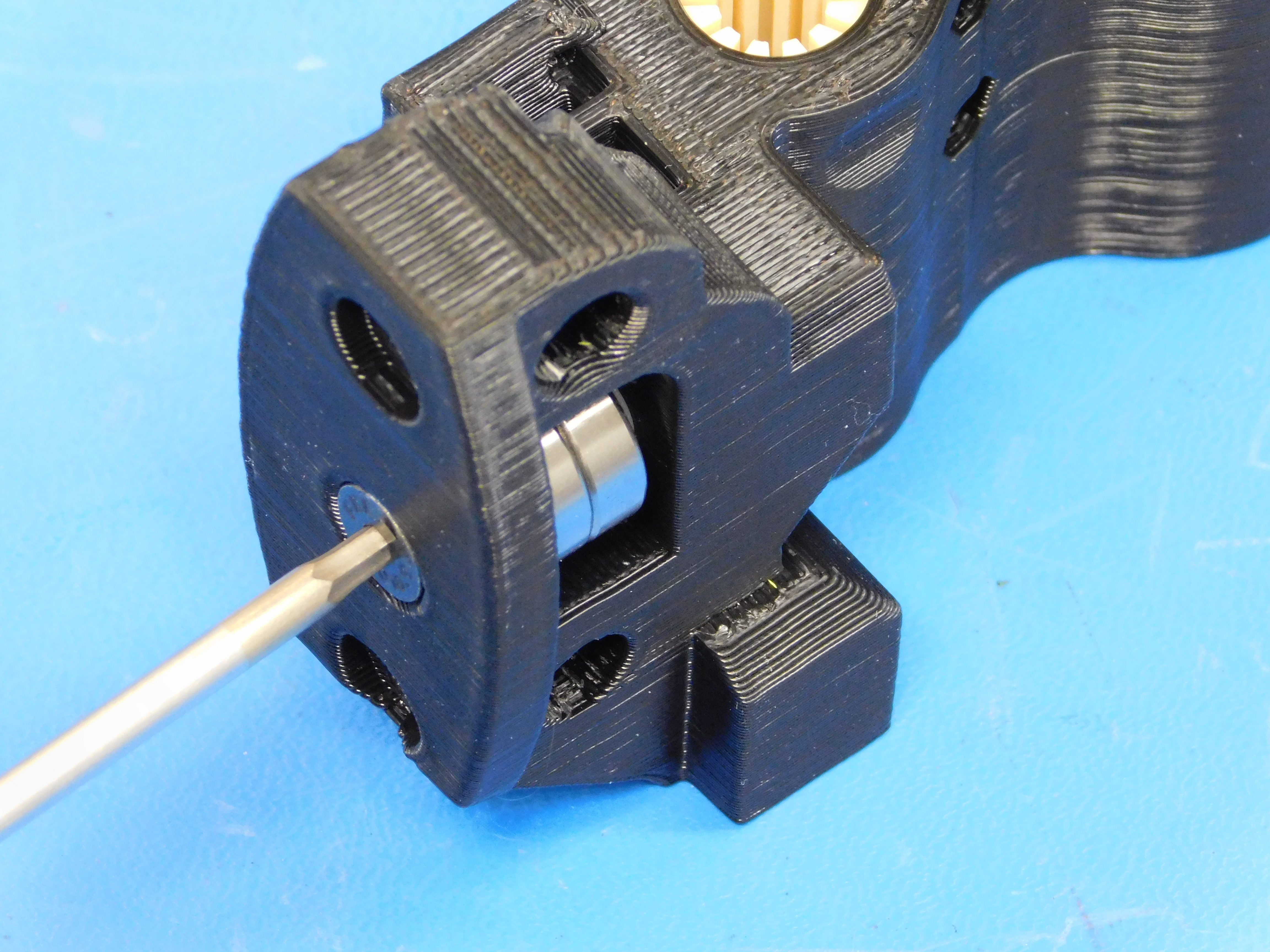
Slide the M5x40mm FHCS [HD-BT0216] through the countersunk hole in the printed part and pass it though the spacer, two bearings, and second spacer, as shown in example photo.
Place the M5 lock nut [HD-NT0057] into the nut trap in the printed part as shown and use a 3 mm hex driver to turn the M5 flat head until finger tight.
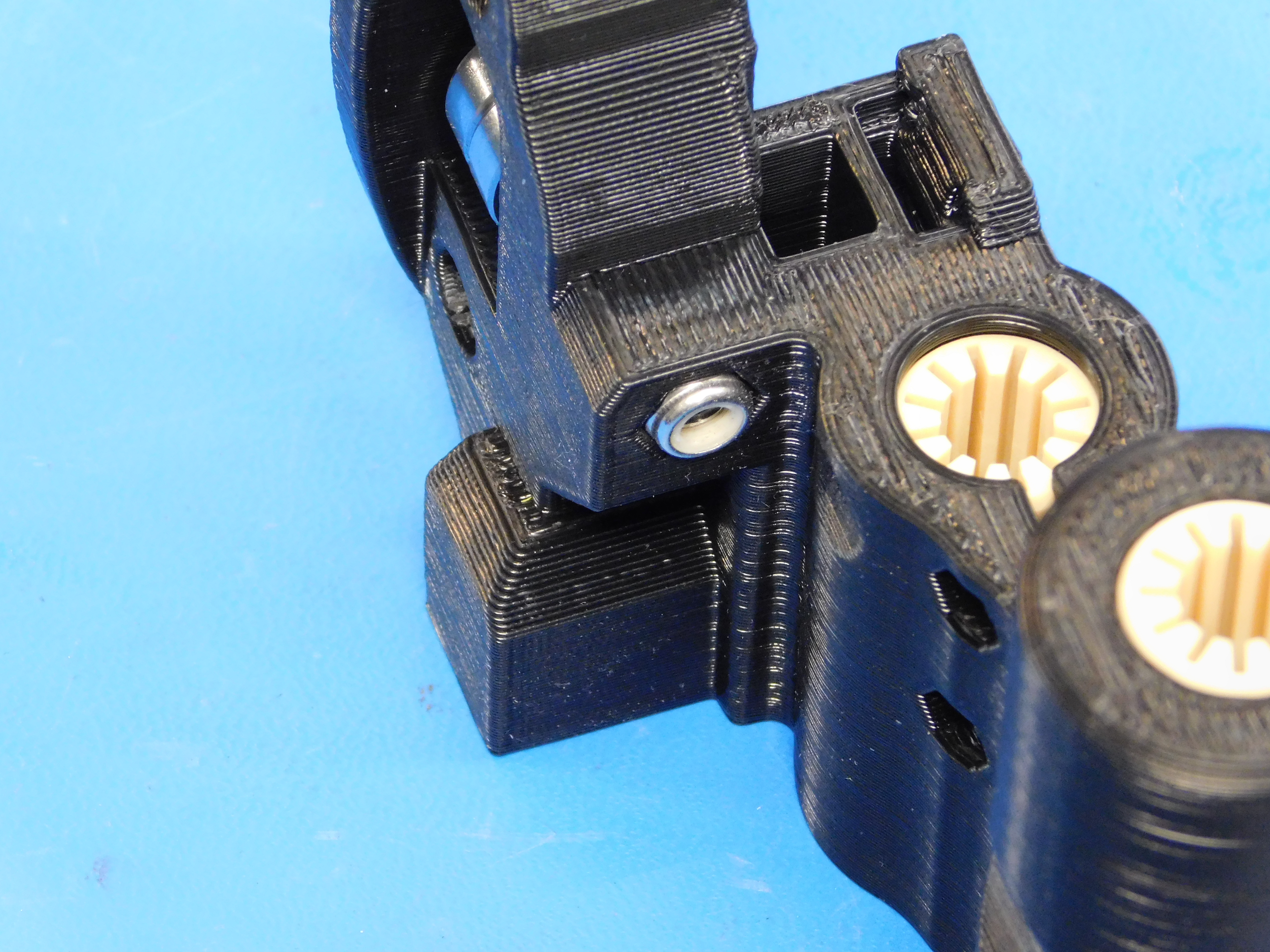
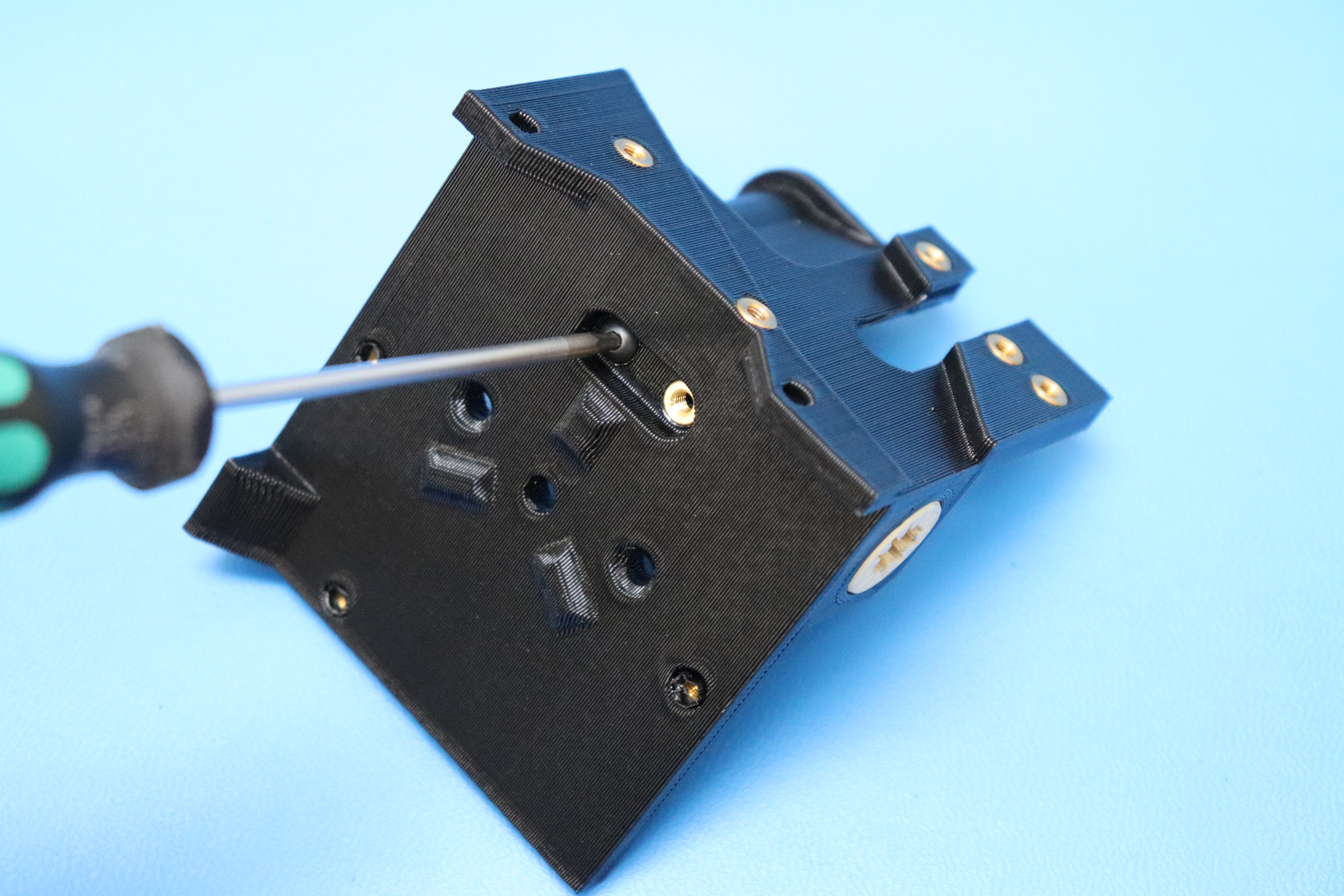
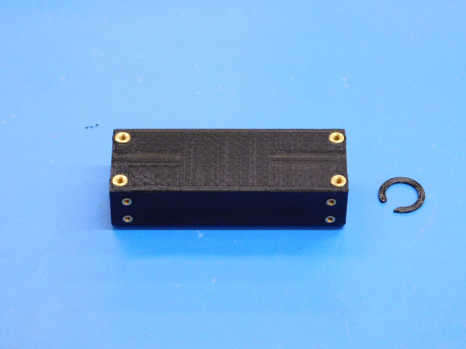
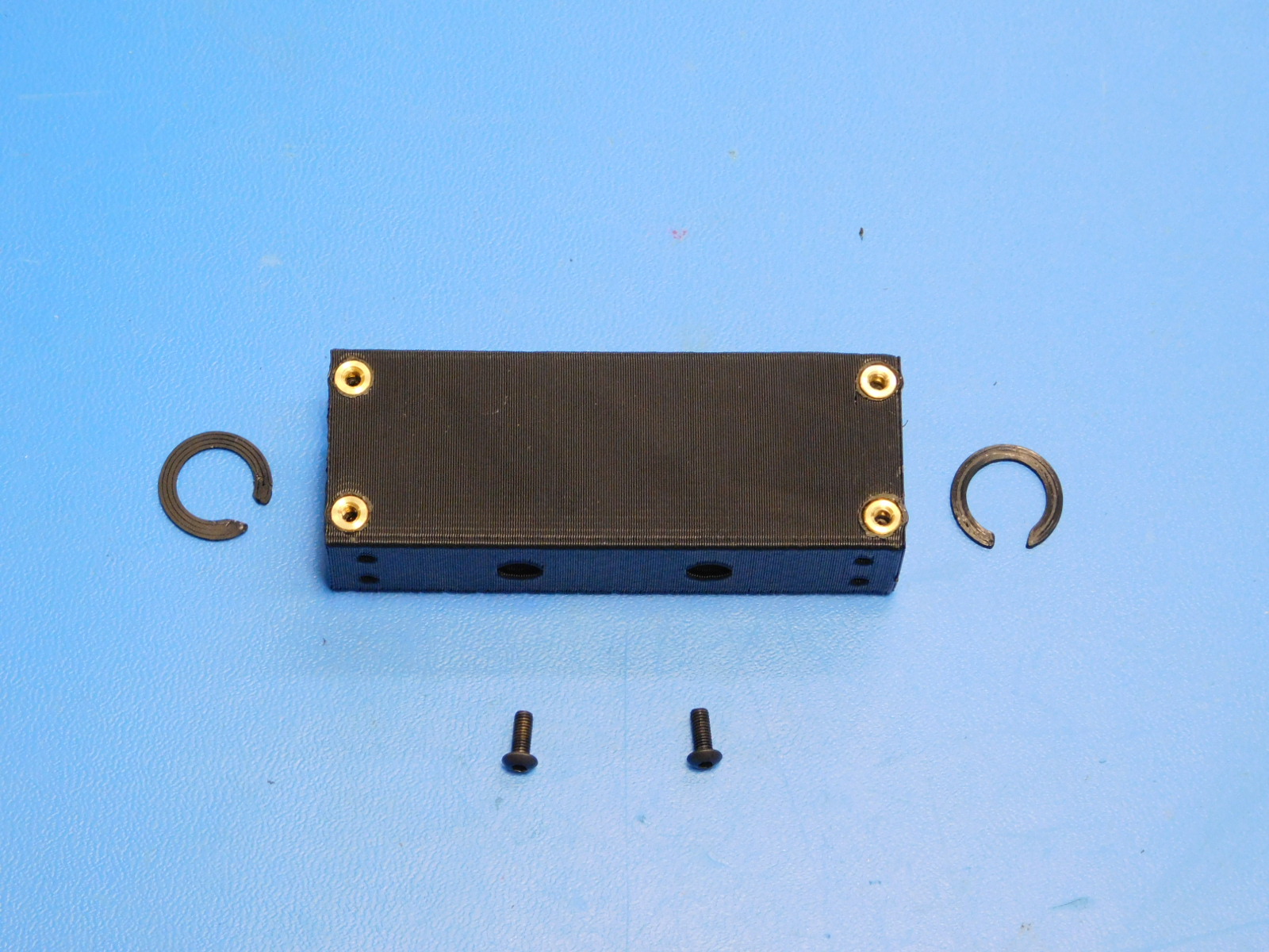
Install the two M3 x 6 mm BHCS [HD-BT0140] to retain the bushings as shown.
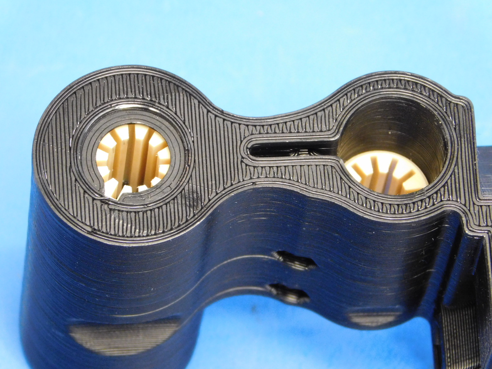
Use your thumb to push both front bushings into the part;
Then install two Retaining Rings [PP-GP0334] one above the top front bushing and one below the bottom front bushing.
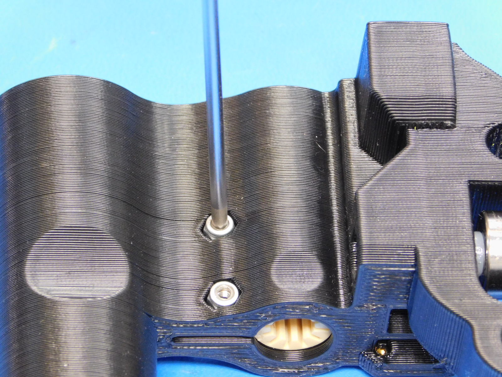
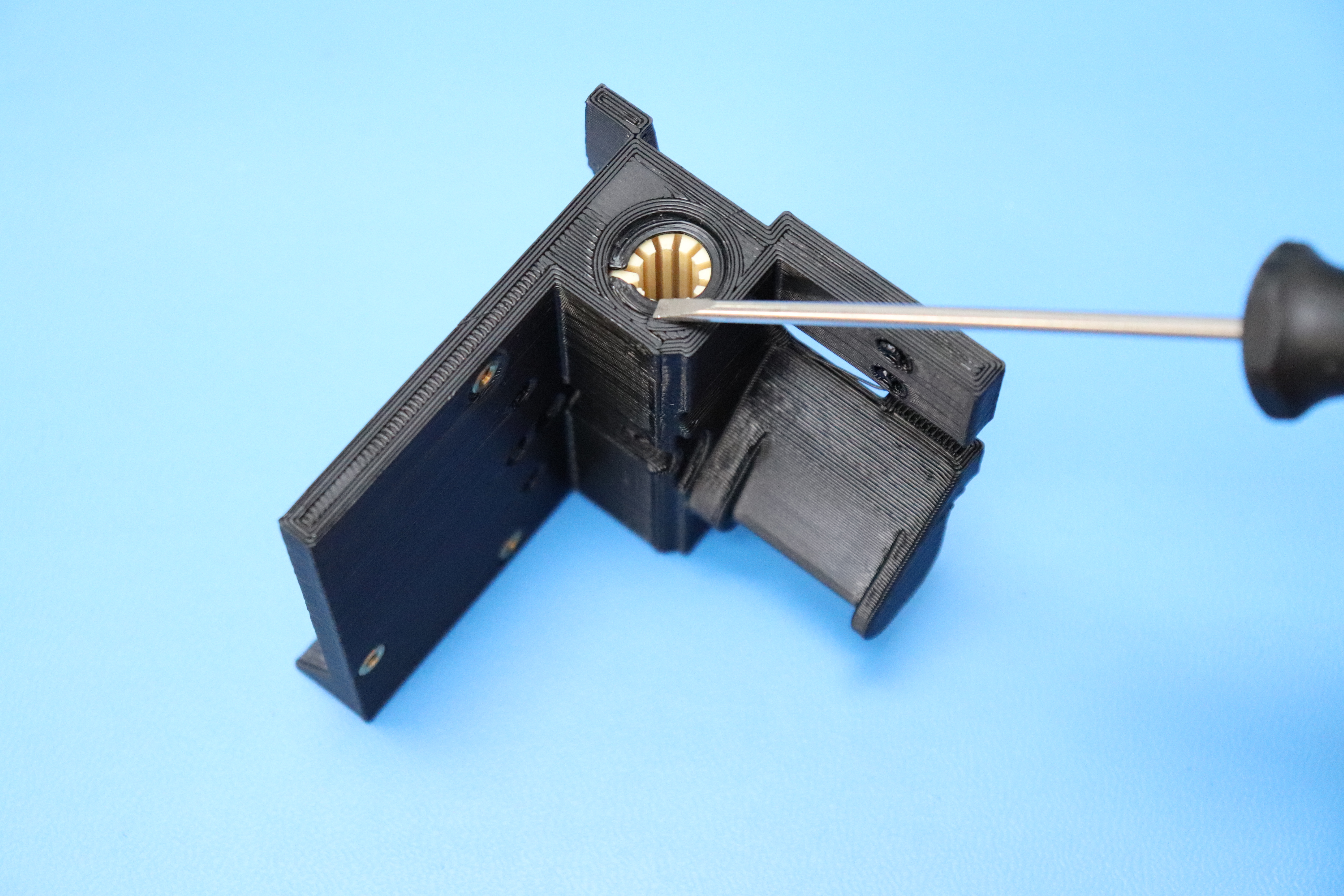
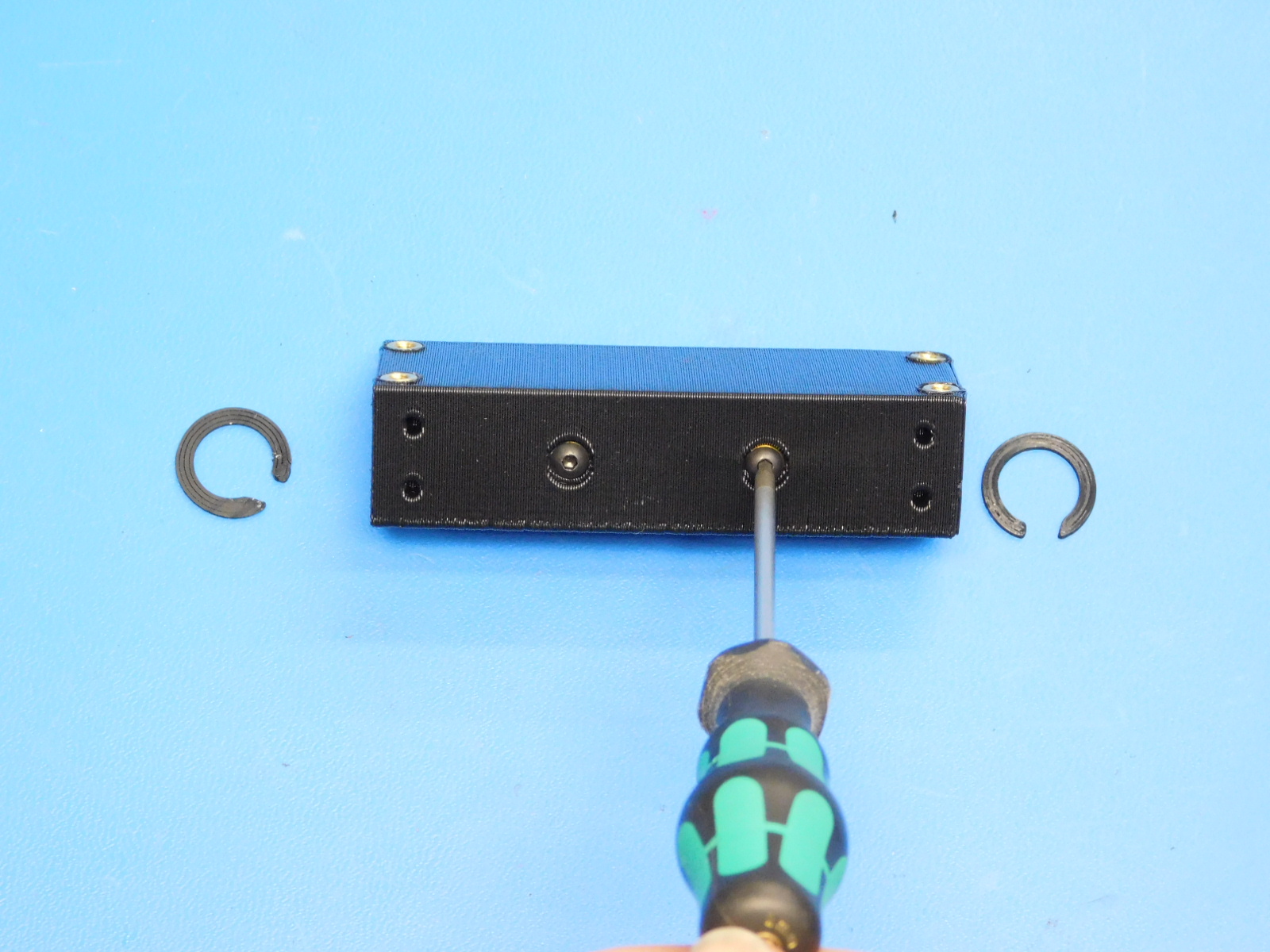
Install the clamping hardware; consuming two M3x12 BHCS [HD-BT0146], two M3 washers [HD-WA0038], and two lock nuts [HD-NT0001].
It is helpful to use the end of a 2mm straight tip hex driver to position the M3 Nyloc Nut in the printed part.
Tighten using setting#2 on the red power drivers
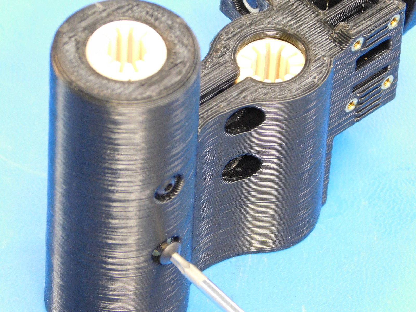
Finally, Install the two M3 x 6 mm set screws [HD-BT0012] into the thermal inserts on the rear of the part as shown.
Materials Required for AS-PR0090:
1x- [AS-PR0094] X End Motor Assembly, Mini 2 (w/ 6x M3 Inserts [HD-MS0030] & 8x M2 Inserts [PP-MP0066] already installed)
1x- [PP-GP0334] Retaining Ring
2x- [HD-BT0140] M3 x 6 Bolt, BHCS Black-Oxide
2x- [HD-BT0146] M3 x 12 BHCS, Black Oxide
2x- [HD-NT0001] Metric Zinc-Plated Steel Nylon-Insert Locknut, Class 8, M3 Screw sz, .5MM pitch
2x- [HD-WA0038] Black-Oxide 18-8 Steel Flat Washer, M3 Screw Size, 3.2mm ID, 7.0mm OD
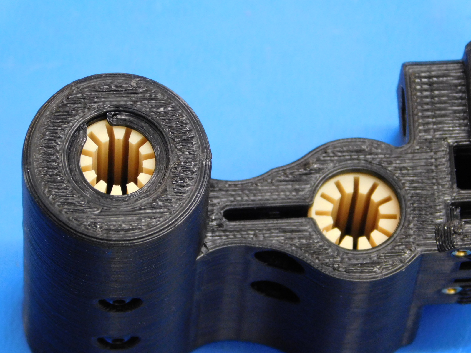
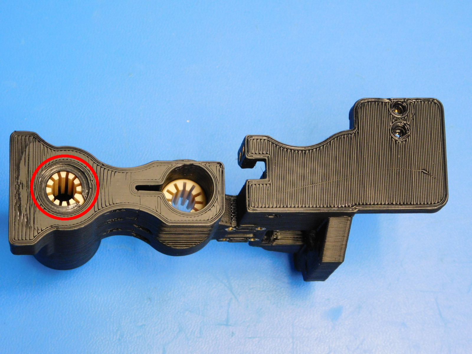
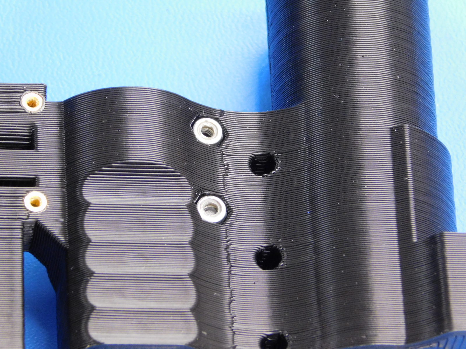
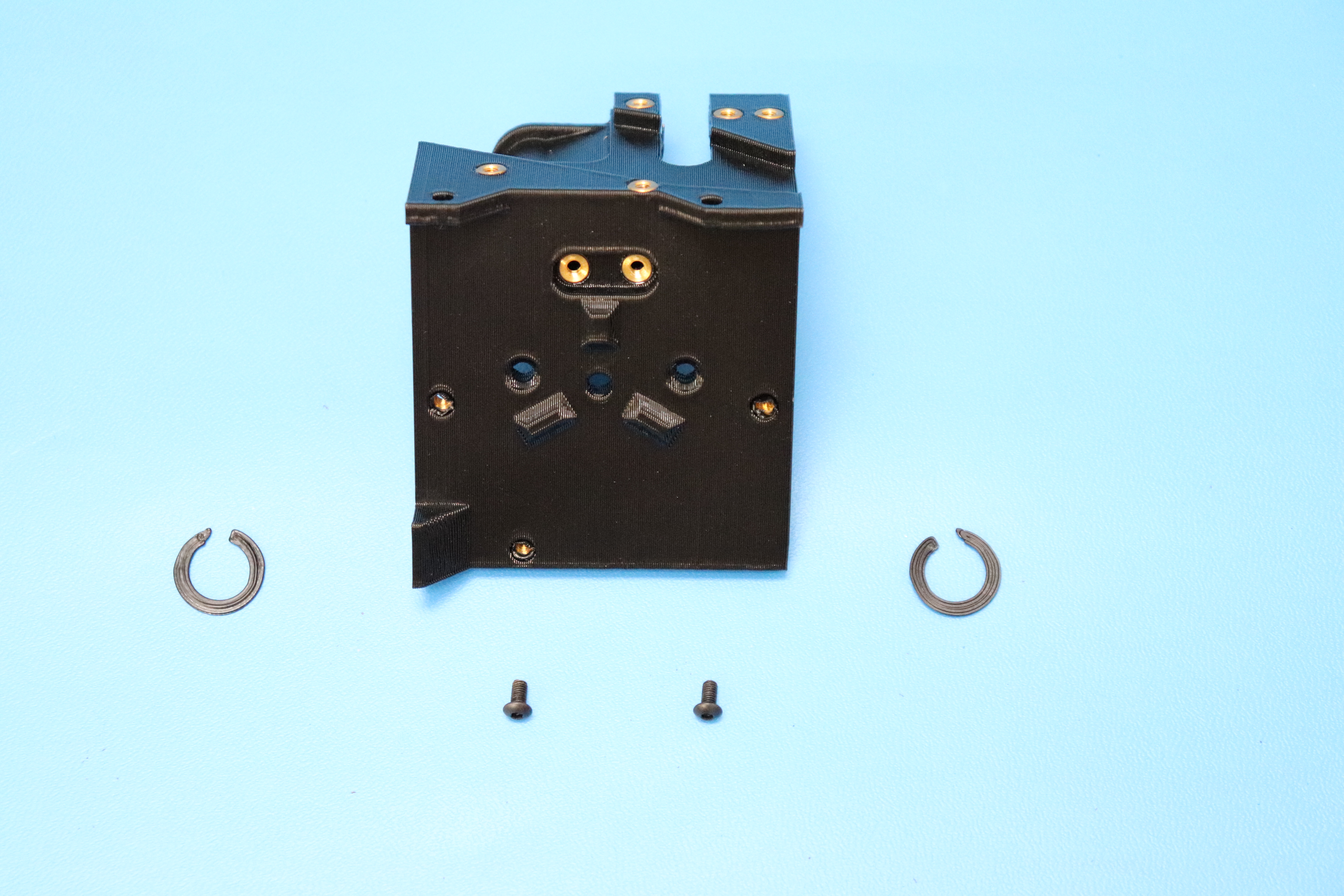
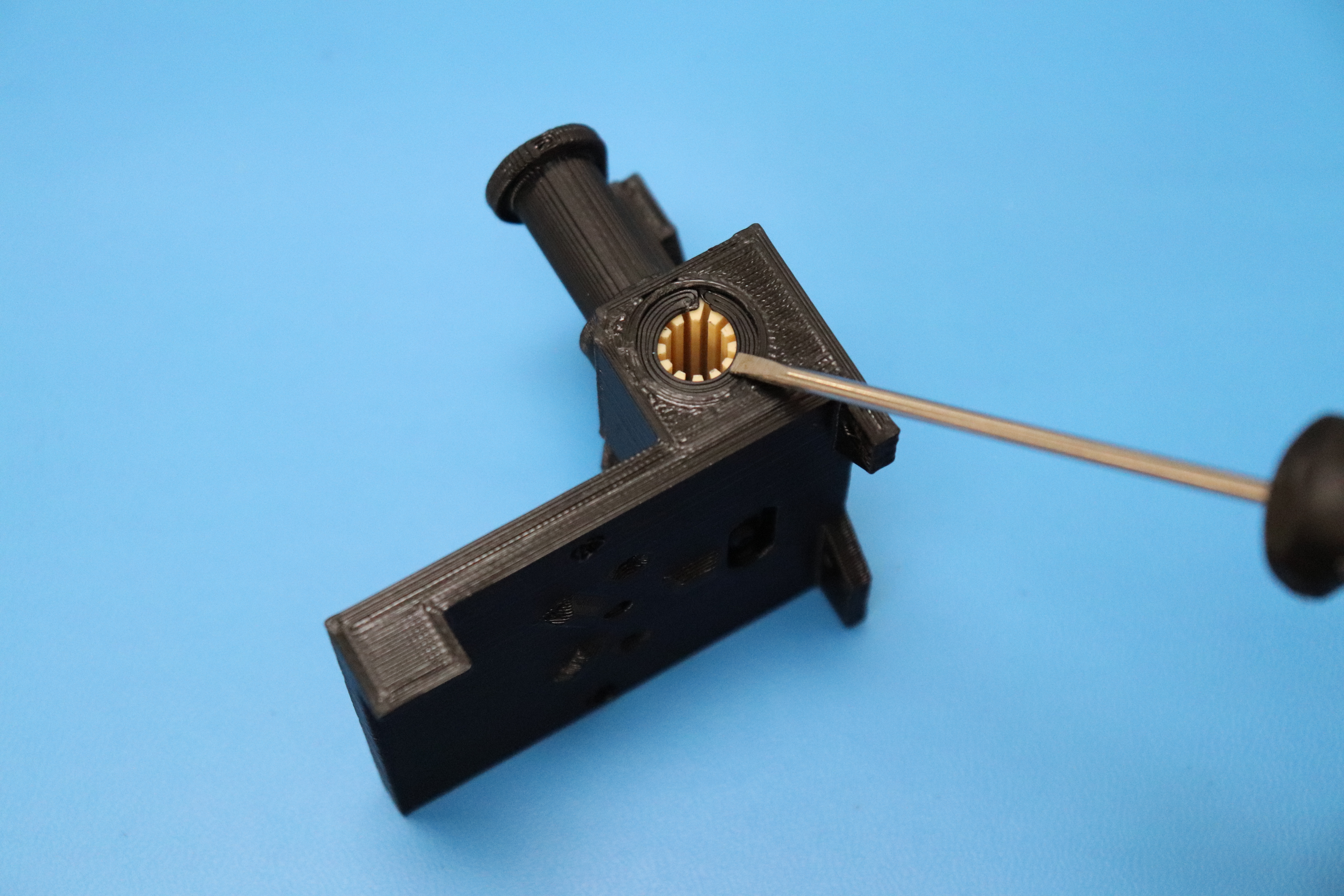
Install the two M3x6 BHCS [HD-BT0140] to retain the bushings as shown.
Use your thumb to push both front bushings into the part;
Install two Retaining Rings [PP-GP0334] one above the top front bushing and one below the bottom front bushing.
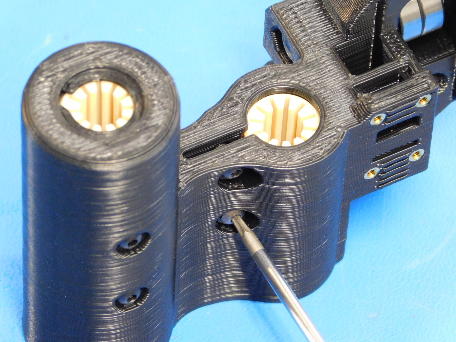
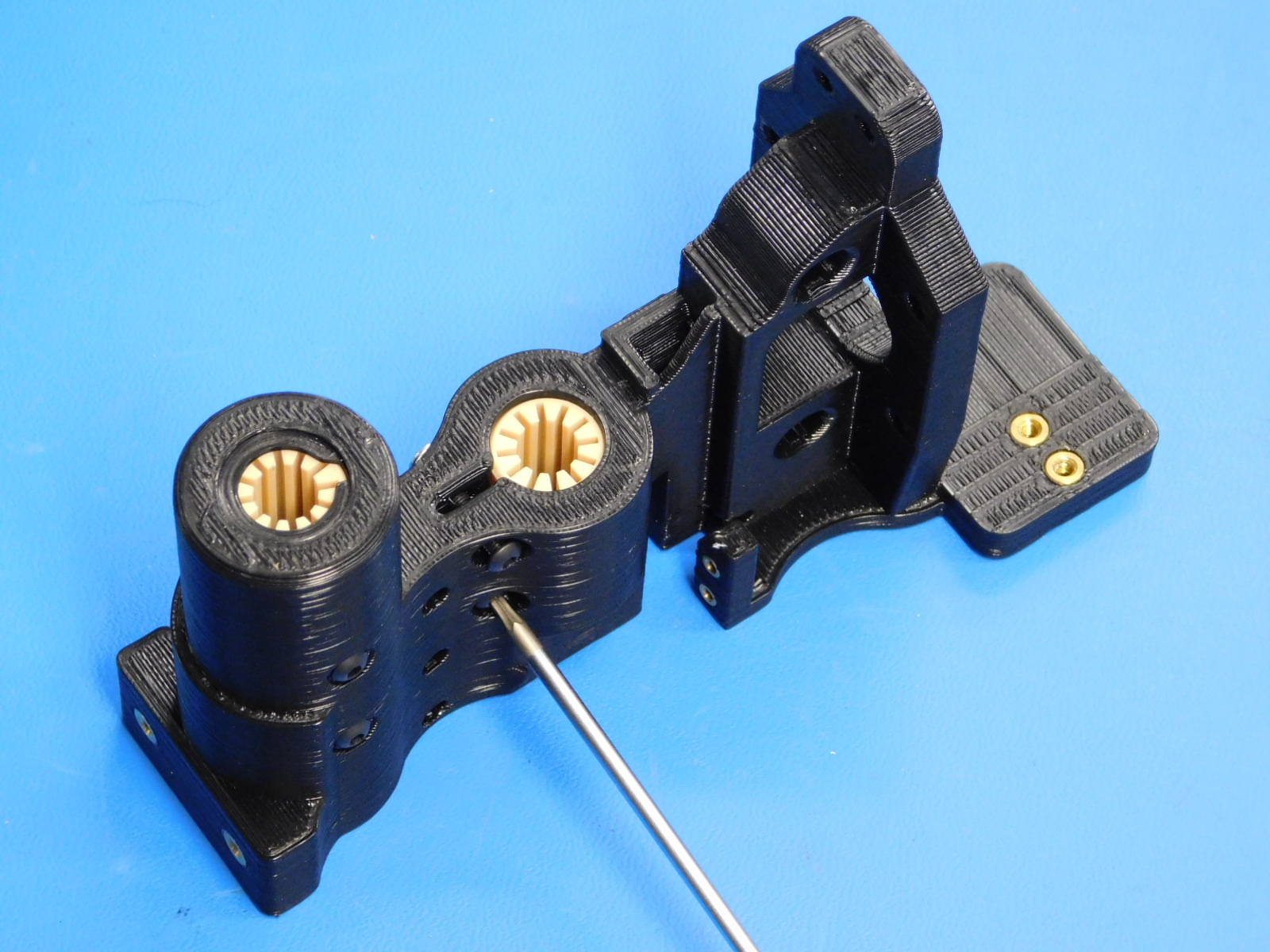
Then, install the clamping hardware consuming two M3x12 BHCS [HD-BT0146], two M3 washers [HD-WA0038], and two lock nuts [HD-NT0001].
It is helpful to use the end of a 2mm straight tip hex driver to position the M3 Nyloc Nut in the printed part.
Tighten using setting#2 on the red power driver
Materials needed:
1x- X-Carriage (with inserts already installed)
2x- [PP-GP0307] Retaining Ring
2x- [HD-BT0140] M3x6 BHCS
Install the two bearing retainer screws M3x6 BHCS [HD-BT0140] as shown, tighten.
Use your thumb to push both bushings into the part; Install two Retaining Rings [PP-GP0334] one on the left, one on the right, as shown.
Materials Required:
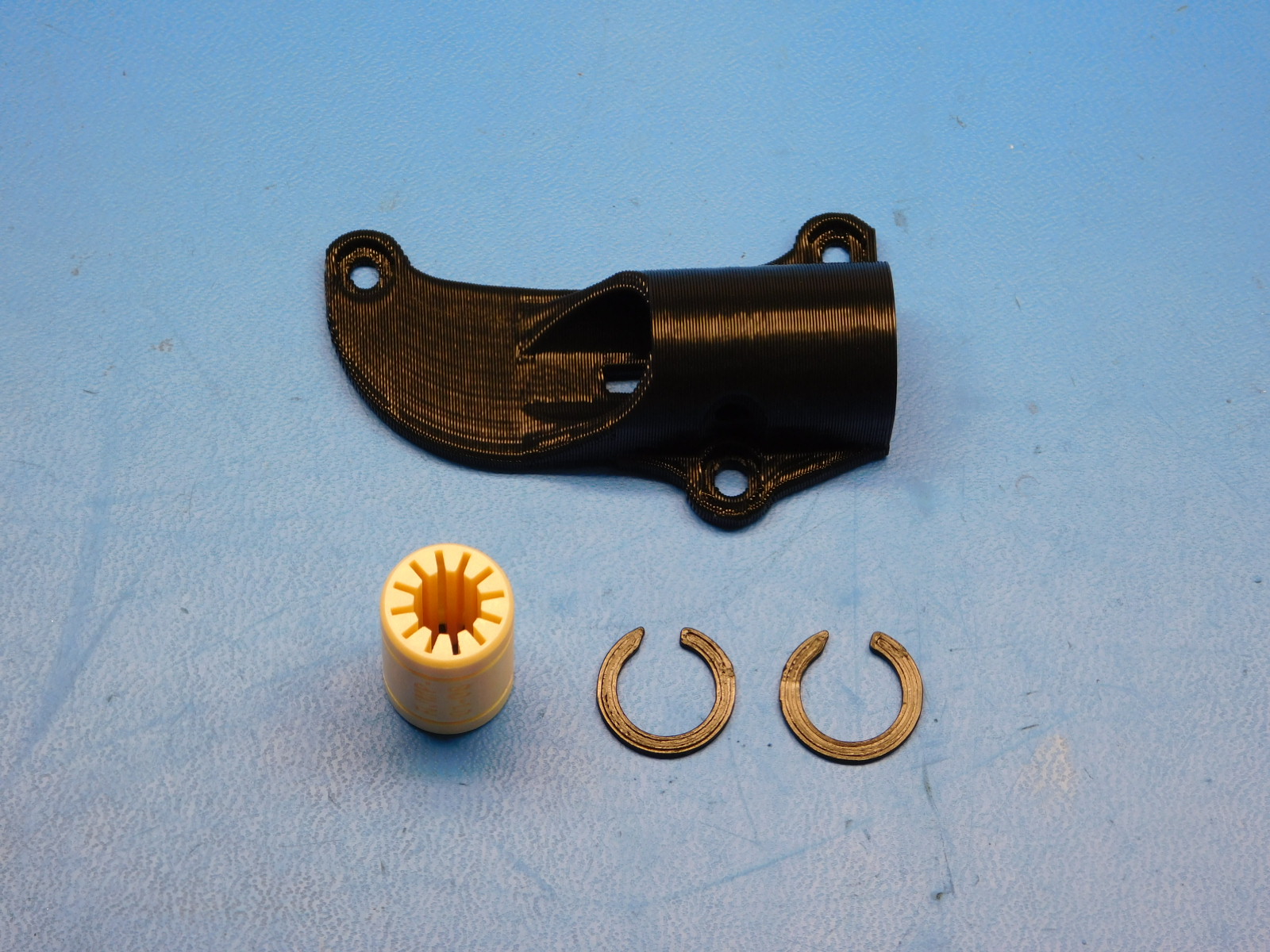
1x- X-Bearing Holder
2x- [PP-GP0334] Retaining Ring
1x- [HD-BT0140] M3x6 BHCS
Use your thumb to push a bushing into the part; Install two Retaining Rings [PP-GP0334] one on the left, one on the right, as shown.

Materials Required for AS-PR0086:
1x- [PP-IS0060] X-Carriage with inserts, Mini 2
1x- [PP-IS0059] X-Bearing Holder Assembly
3x- [HD-BT0137] M3 x 8 Bolt, BHCS, Black-Oxide
3x- [HD-WA0038] Black-Oxide 18-8 Steel Flat Washer, M3 Screw Size, 3.2mm ID, 7.0mm OD
2x- [HD-BT0116] M3x10 FHCS
Using three M3 x 8 mm BHCS [HD-BT0137] fasten the x bearing holder [PP-IS0059] to the x carriage [AS-PR0096]. These screws may be left loose at this time.
Using two M3x10 FHCS [HD-BT0116] fasten the X-Belt Mount [PP-ISxxxx] to the rear of the X-Carriage, ensure the belt mount is fastened securely.
Materials required:
1x- Mini 2 Single Bearing Holder (M2 & M3 inserts already installed)
1x- [PP-GP0307] Retaining Ring
Install one Retaining Ring [PP-GP0334] to the groove next to the bearing on the notched side of the printed part, as shown.
Materials Required:
1x- Mini 2 Double Bearing Holder (with M3 inserts already installed)
2x- [PP-GP0307] Retaining Ring
2x- [HD-BT0137] M3x8 BHCS
Install the two bearing retainer screws M3x8 BHCS [HD-BT0137] as shown, tighten.
Use your thumb to push both bushings into the part; Install two Retaining Rings [PP-GP0334] one on the left, one on the right, as shown.
Materials Required:
1x- [PP-GP0309] Z-Upper Left, Mini 2
1x- [HD-MS0030] M3 Brass Inserts
1x- [HD-MS0412] Smooth Idler Pulley Wheel Kit
Please see Step 20 of the Thermal Inserts OHAI for proper placement of the inserts.
Contained in the Smooth Idler Puller Wheel Kit [HD-MS0412]:
1x- M5 Screw
1x- M5 Nyloc Nut
1x- Pulley
2x- Bearings
1x- M5 washer
1x- Nylon Spacer DISCARD THIS SPACER DO NOT CONFUSE WITH HD-MS0427
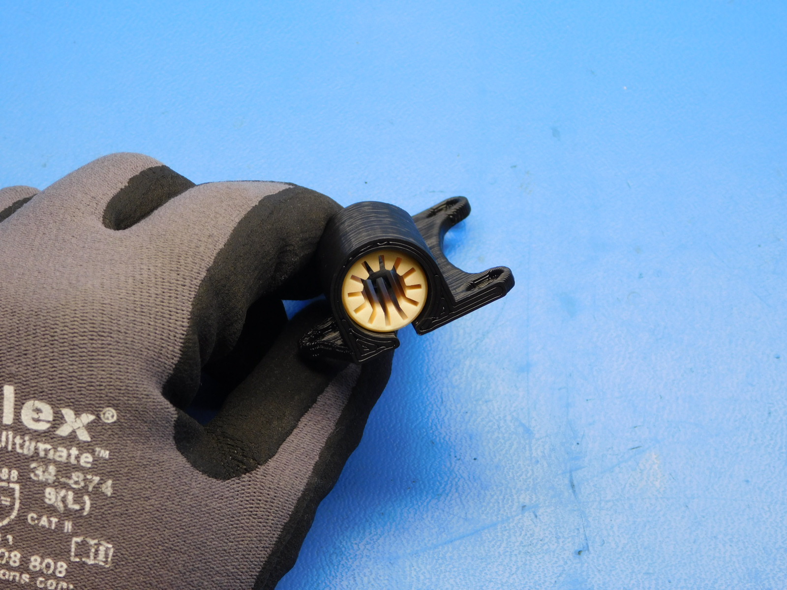
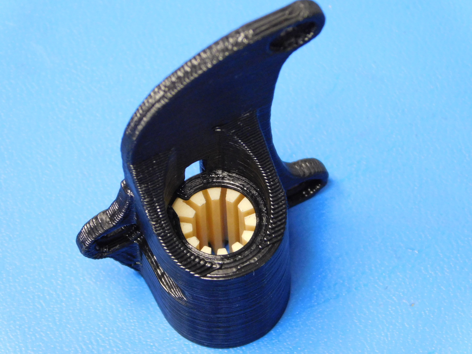
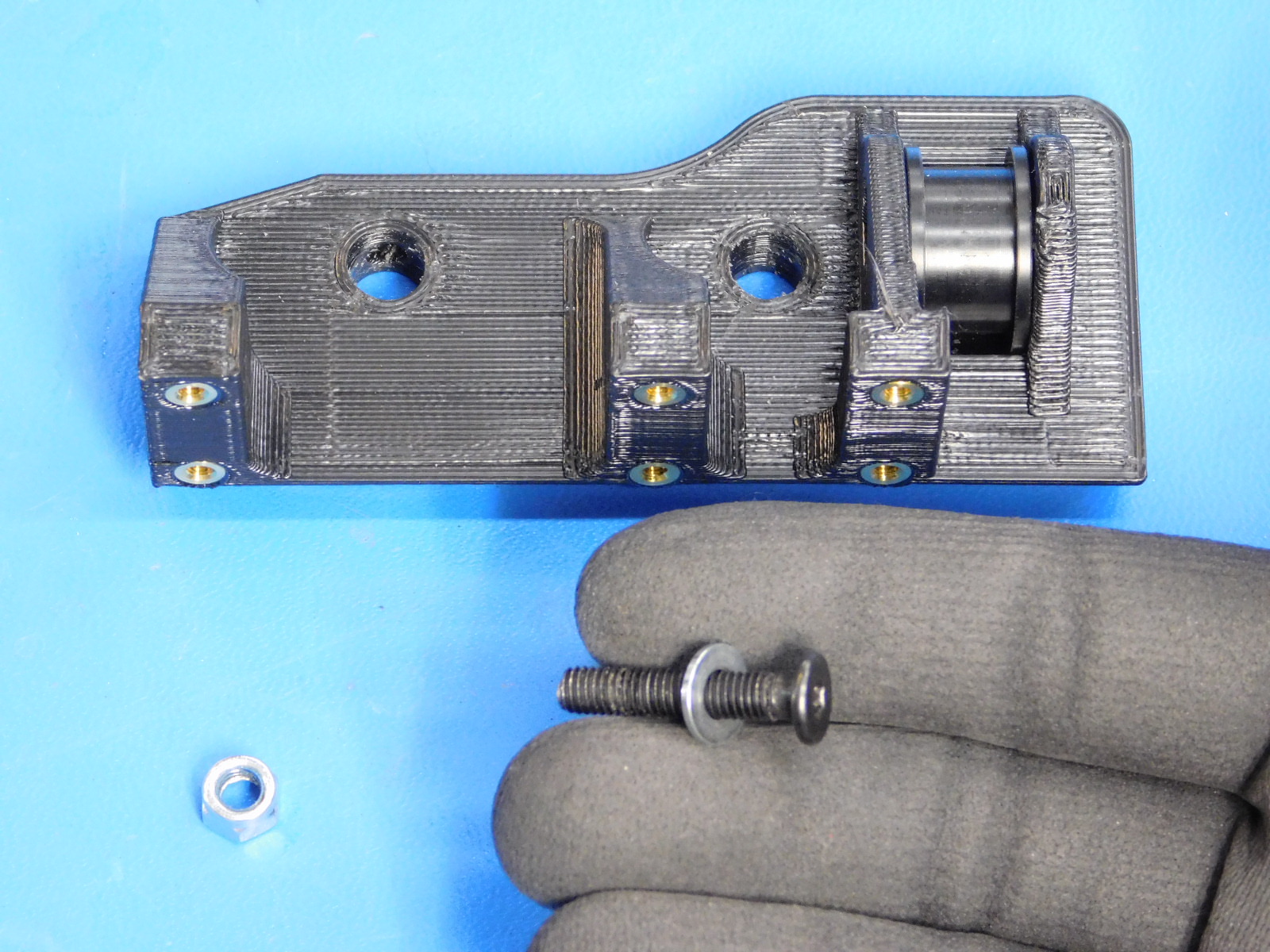
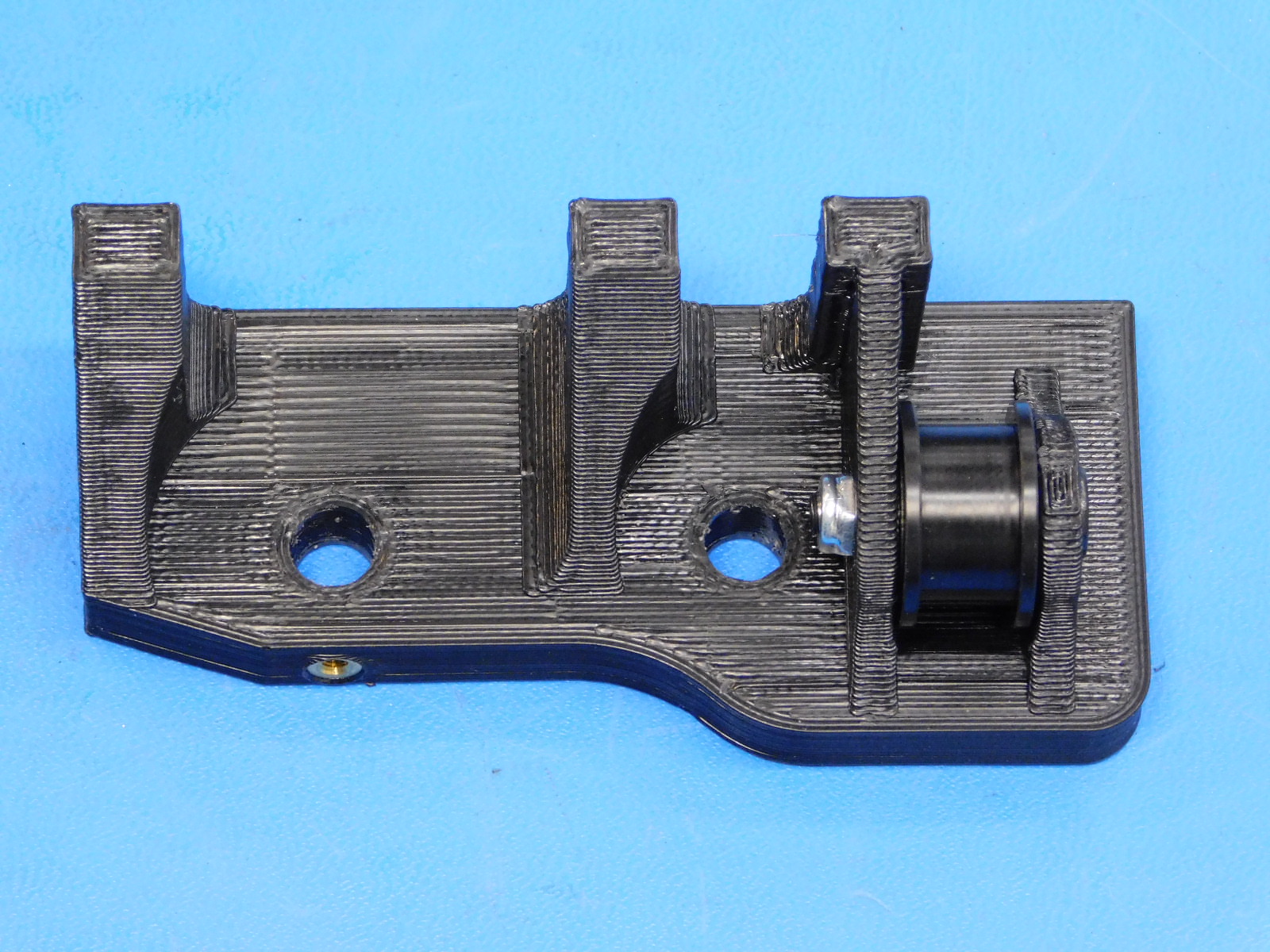
To complete this assembly, first hand insert the bearings into the injection molded Pulley if this has not already been completed.
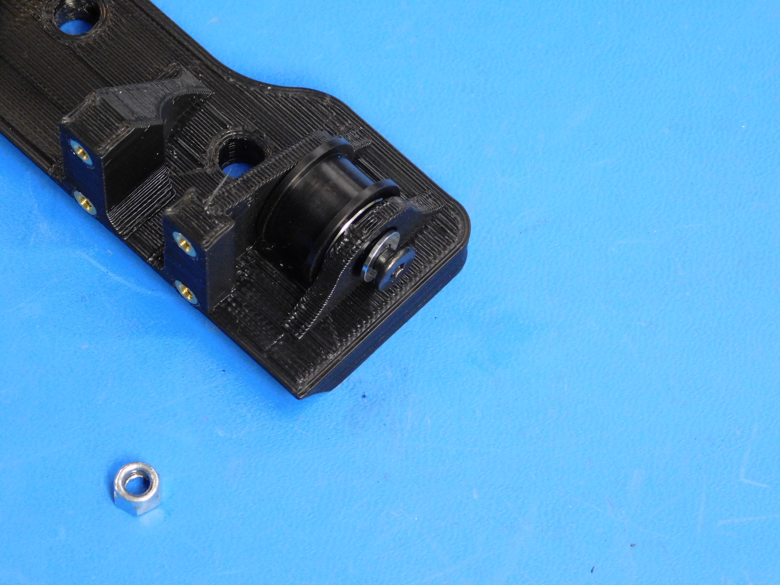
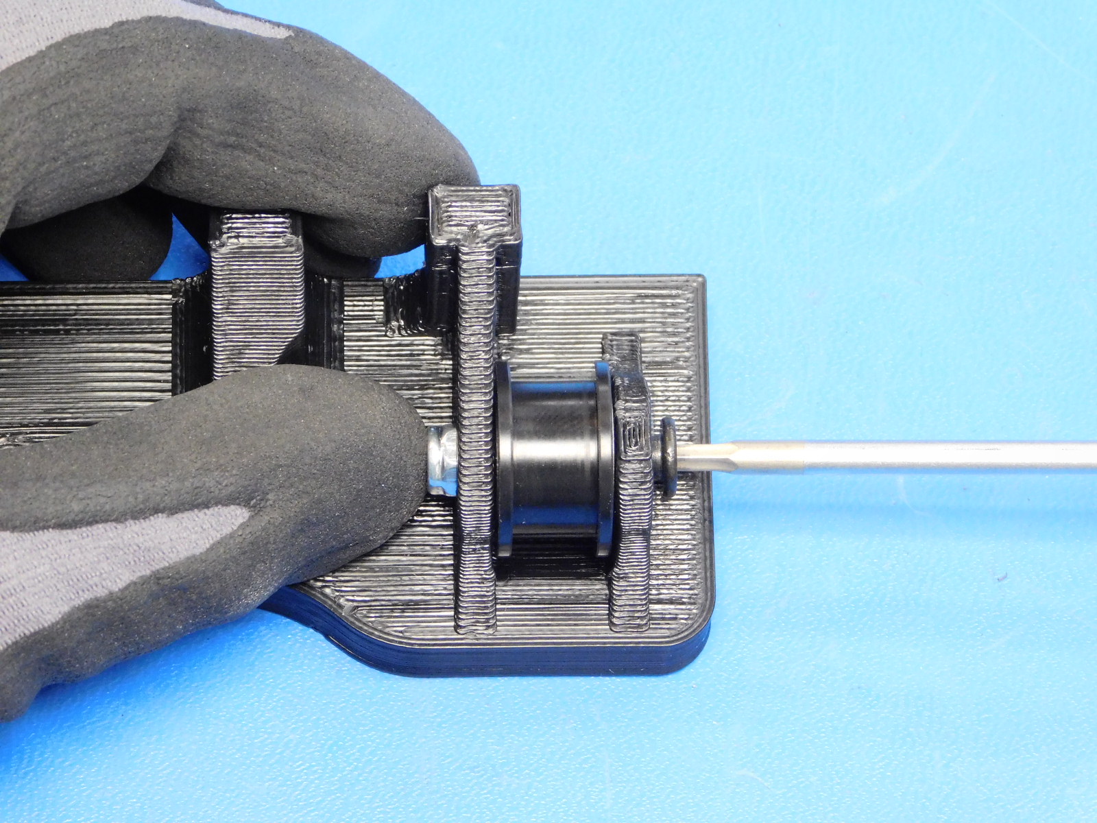
Then drop the pulley in between the flanges of the Z-Upper Left [PP-IS0050]
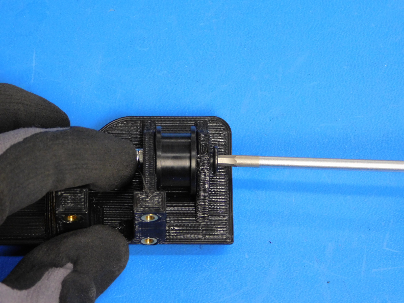
Slide the M5 washer onto the M5 screw and thread through the printed part from the outside and through the bearings of the Pulley.
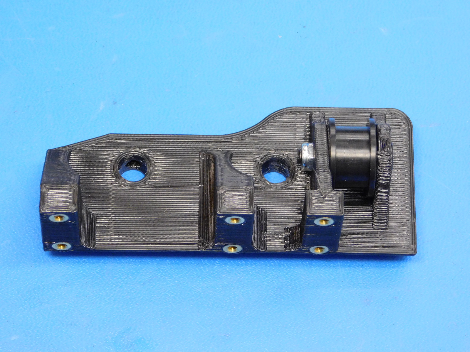
Place the M5 nut into the pocket on the inner flange, hold by hand while tightening the M5 screw.
Tighten until the M5 nut and bolt do not move freely in the printed part; the M5 screw must not be over-tightened, ensure the idler pulley spins freely.
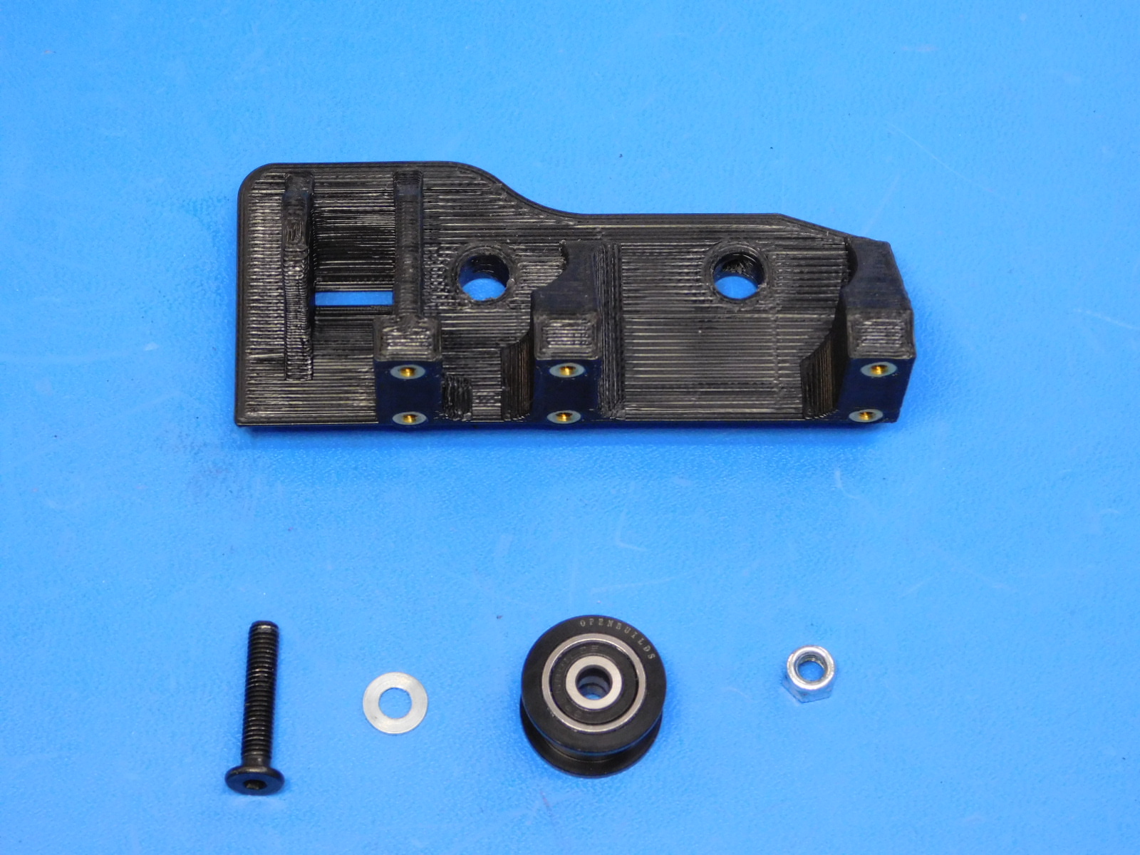
Materials Required to complete AS-PR0088:
1x- [PP-GP0312] Z-Upper Right, Mini 2
7x- [HD-MS0030] M3 Brass Insert
1x- [HD-MS0412] Smooth Idler Pulley Wheel Kit
Please see Step 19 of the Thermal Insert OHAI for proper placement of the inserts.
Contained in the Smooth Idler Puller Wheel Kit [HD-MS0412]:
1x- M5 Screw
1x- M5 Nyloc Nut
1x- Pulley
2x- Bearings
1x- M5 washer
1x- Nylon Spacer DISCARD THIS SPACER DO NOT CONFUSE WITH HD-MS0427
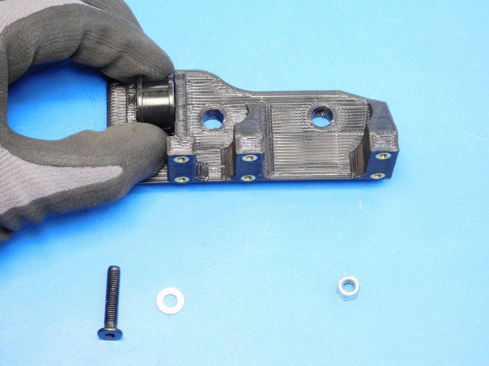
To complete this assembly, first hand insert the bearings into the injection molded Pulley if this has not already been completed.
Then drop the pulley in between the flanges of the Z-Upper Right [PP-IS0048]
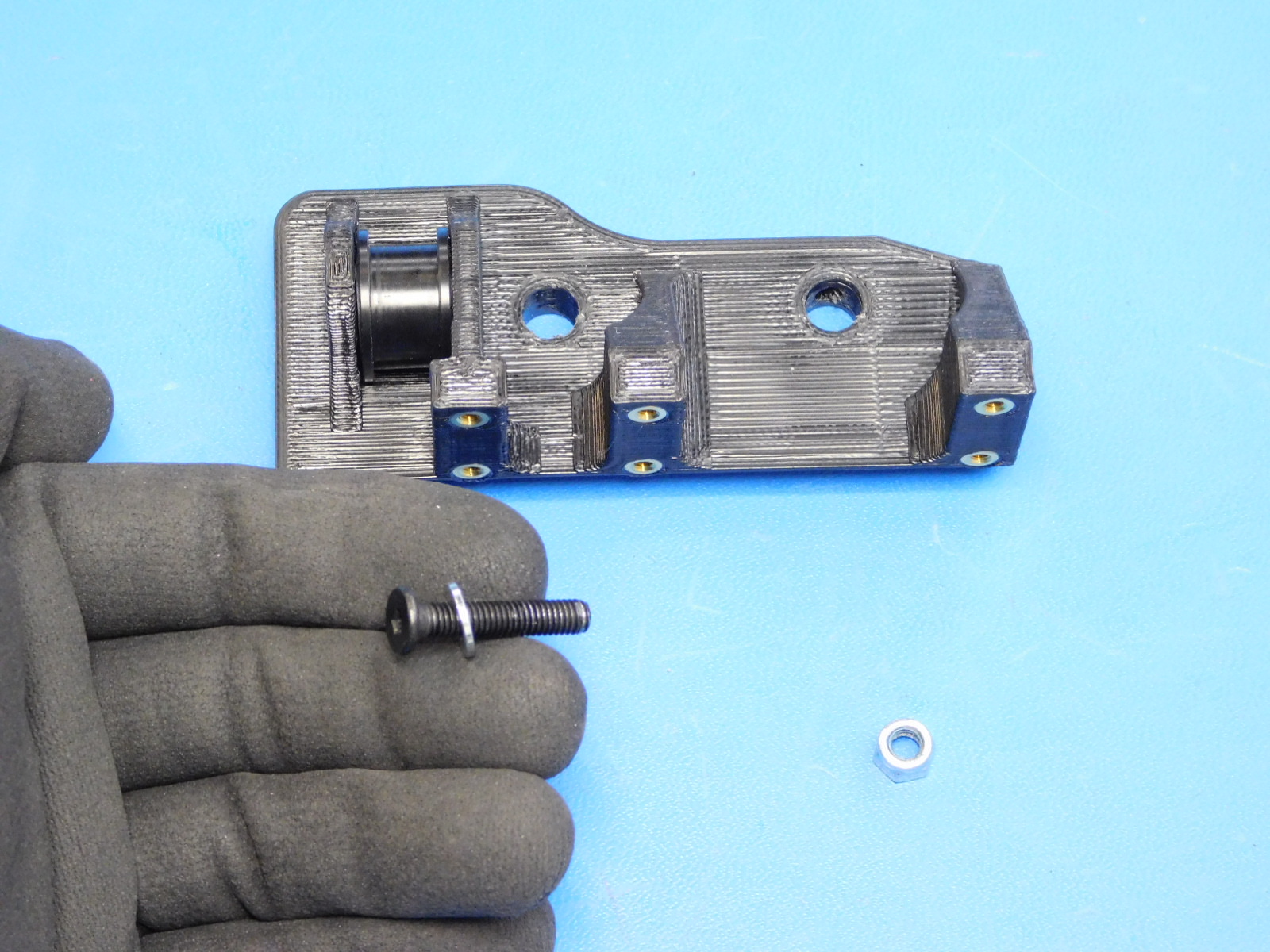
Slide the M5 washer onto the M5 screw and thread through the printed part from the outside and through the bearings of the Pulley.
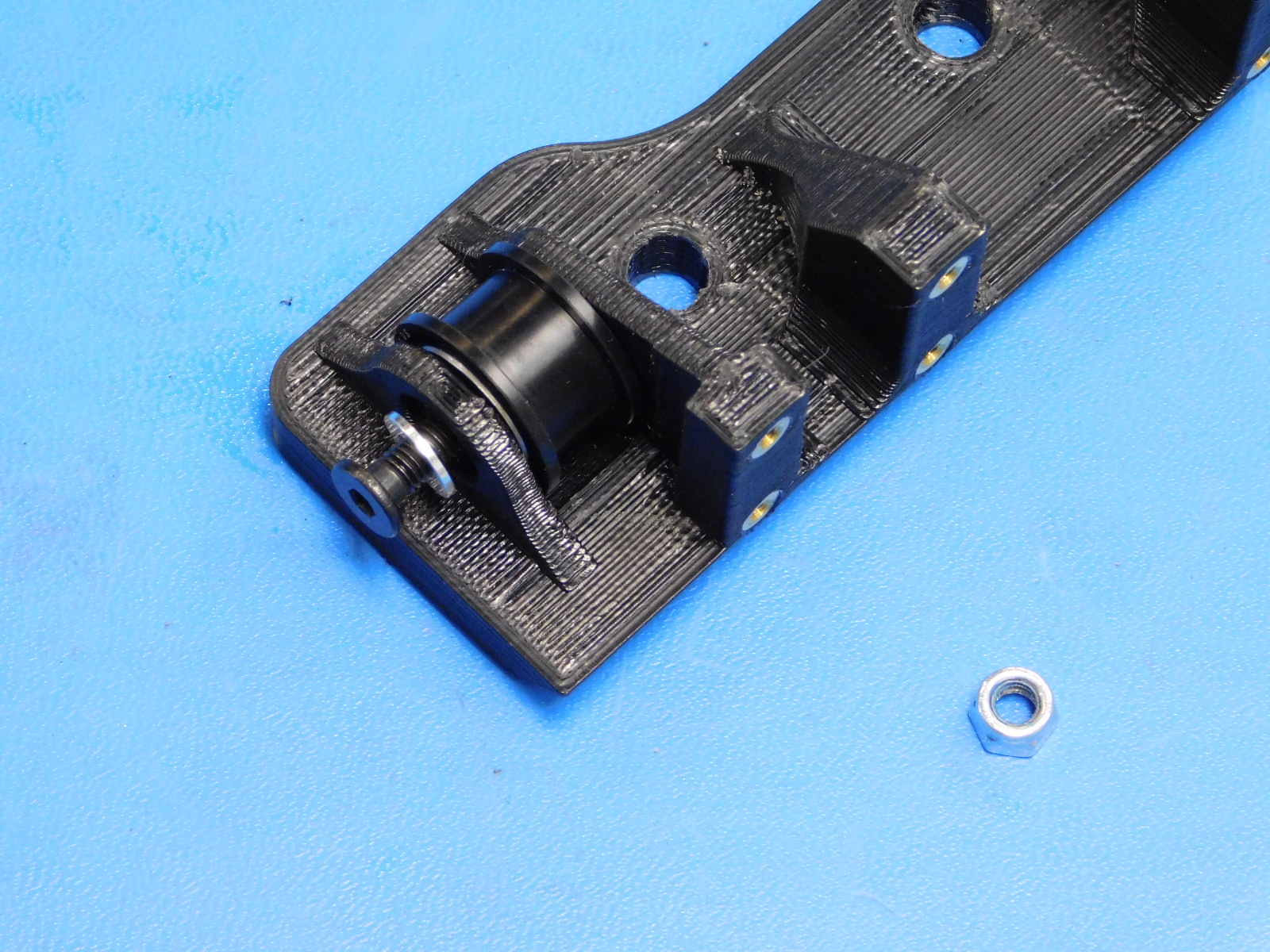
Place the M5 nut into the pocket on the inner flange, hold by hand while tightening the M5 screw.
Tighten until the M5 nut and bolt do not move freely in the printed part; the M5 screw must not be over-tightened, ensure the idler pulley spins freely.
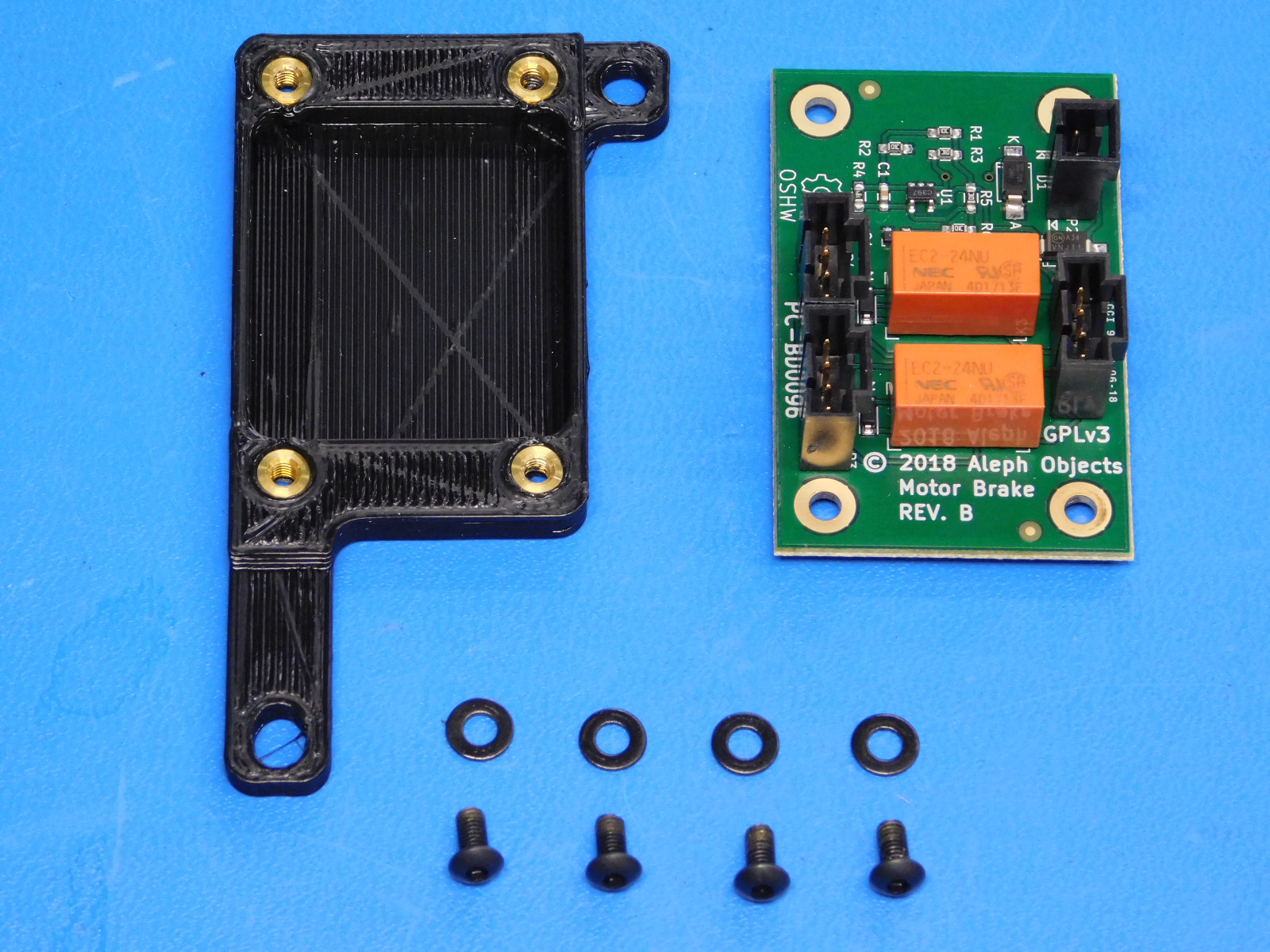
Materials required:
1x- [PC-BD0096] Z-Brake Board
1x- [PP-IS0058] Z-Brake Mount w/ Inserts
4x- [HD-BT0140] M3x6 BHCS
4x- [HD-WA0038] M3 Black Washers
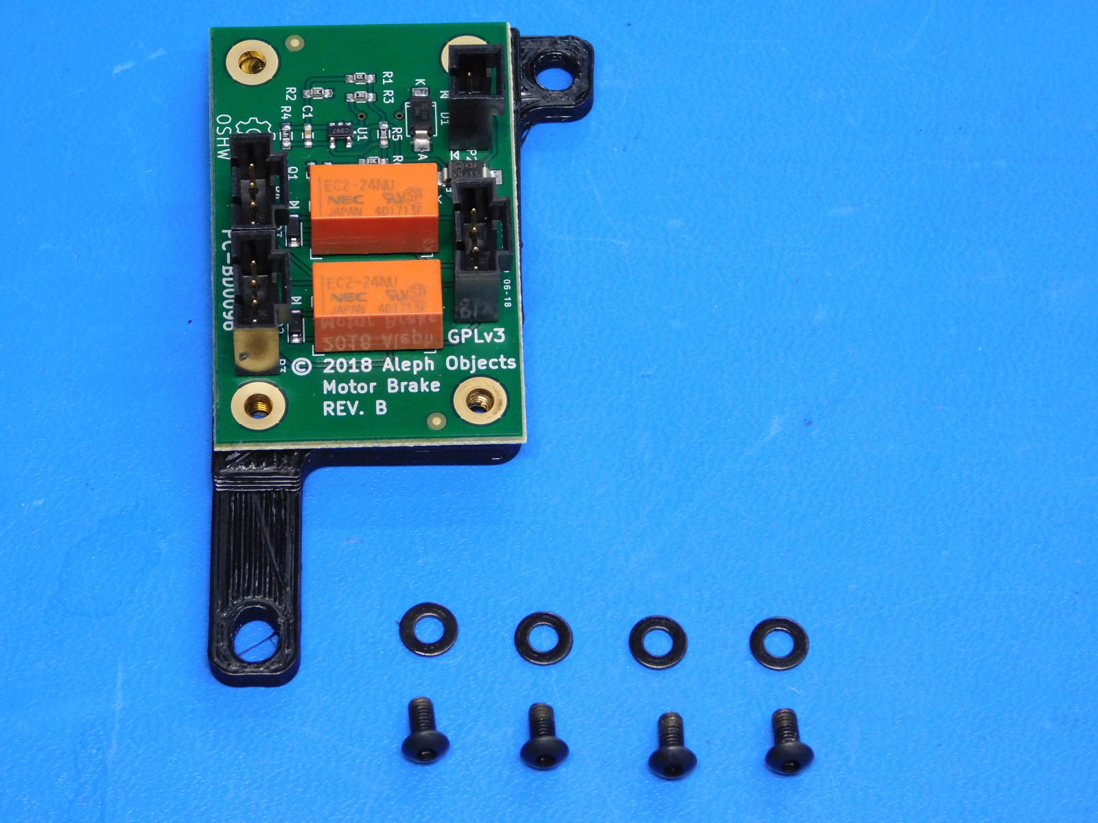
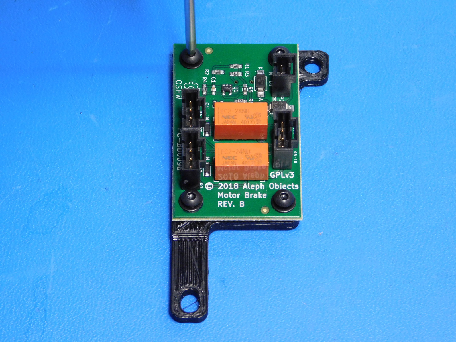
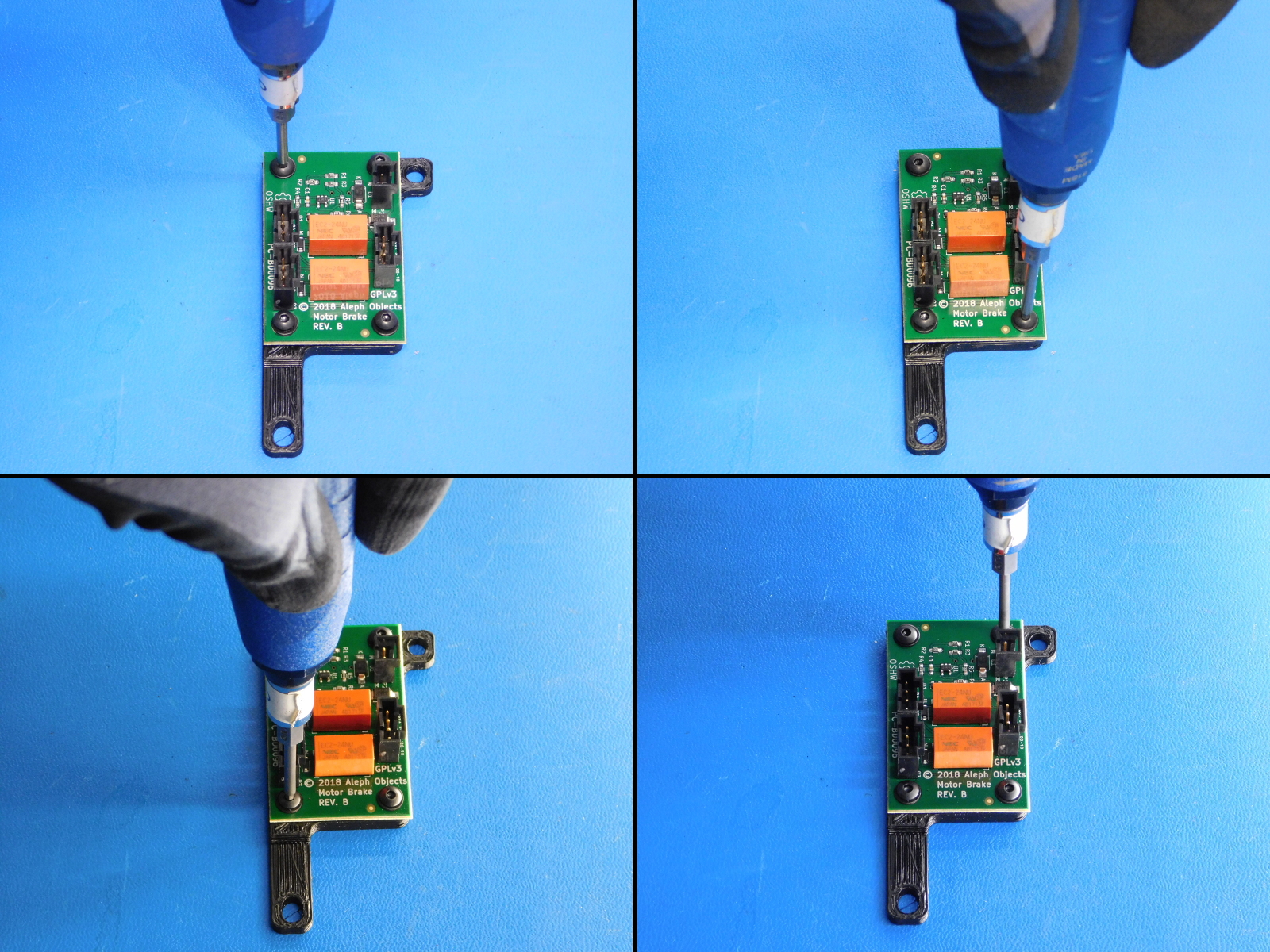
Attach the Z-Brake Board [PC-BD0096] to the Z-Brake Mount w/ Inserts [PP-IS0058] using four M3x6 BHCS [HD-BT0140] with washers [HD-WA0038]
Torque fasteners to 3in*lbs