Open HardwareAssembly Instructions
Guides for installation and assembly of the LulzBot line of products made by Aleph Objects, Inc.
Guides for installation and assembly of the LulzBot line of products made by Aleph Objects, Inc.
2x- [HD-BT0049] M5x14 SHCS, Black-Oxide
1x- [HD-BT0225] M5x10 BHCS Stainless Steel
67x- [HD-BT0073] M5x10 BHCS, Black-Oxide
4x- [HD-EX0062] T-Slot Aluminum Extrusion 500mm,Tapped on Both Ends, Black
4x- [HD-EX0086] T-Slot Extrusion, Aluminum, 530mm
8x- [HD-EX0090] 90 degree 2 Hole 20mm Slotted Inside Corner Bracket with Dual Support
1x- [HD-EX0092] 2 Hole Inside Corner Bracket For 20 Series
4x-[ HD-NT0044] Post assembly M5 T-nut
68x- [HD-NT0053] T-Slot Slide in T-nuts for Aluminum Frame, M5
1x- [HD-WA0007] M5 Washer, Steel, Zinc Plated
69x- [HD-WA0040] M5 Washer, Black-Oxide
8x- [PP-FP0152] Corner Bracket
1x- [PP-GP0410] Electronic Chassis Mount-Front
2x- [PP-GP0411] Electronic Chassis Mount-Back
4x- [PP-GP0409] Frame Foot
1x- [AS-PR0011] TAZ6, Tippy Feed Tube Holder with Bushing Assembly
4x- [PP-IS0098] Bed Mount Chassis with Insert
1x- [EL-HR0142] Z Endstop Harness, Assembled
1x- [AS-PR0150] T-Slot dust cover, cut, 285mm
1x- [AS-PR0151] T-Slot Dust cover, cut, 522mm
1x- [AS-PR0137] Spool Arm Assembly
1x- [AS-PR0130] X-End Right Assembly
1x- [AS-PR0164] X End Left, Workhorse
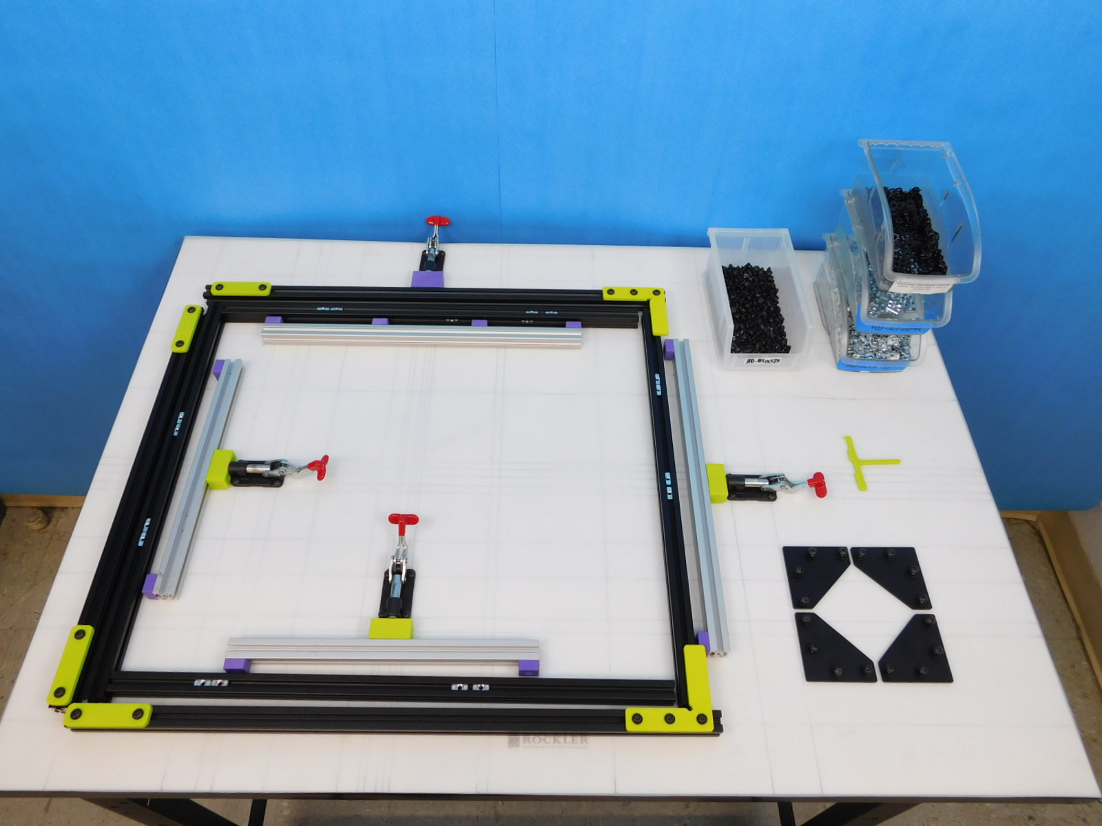
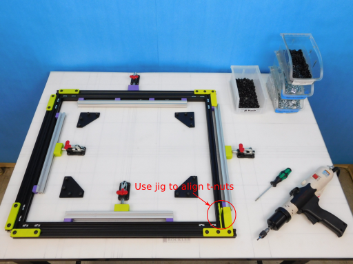
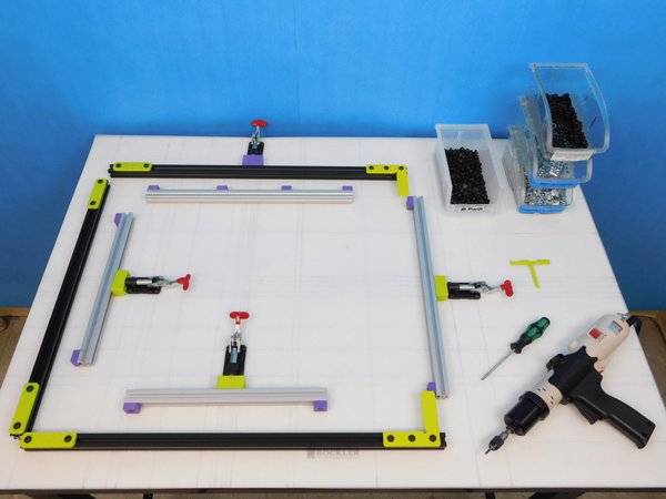
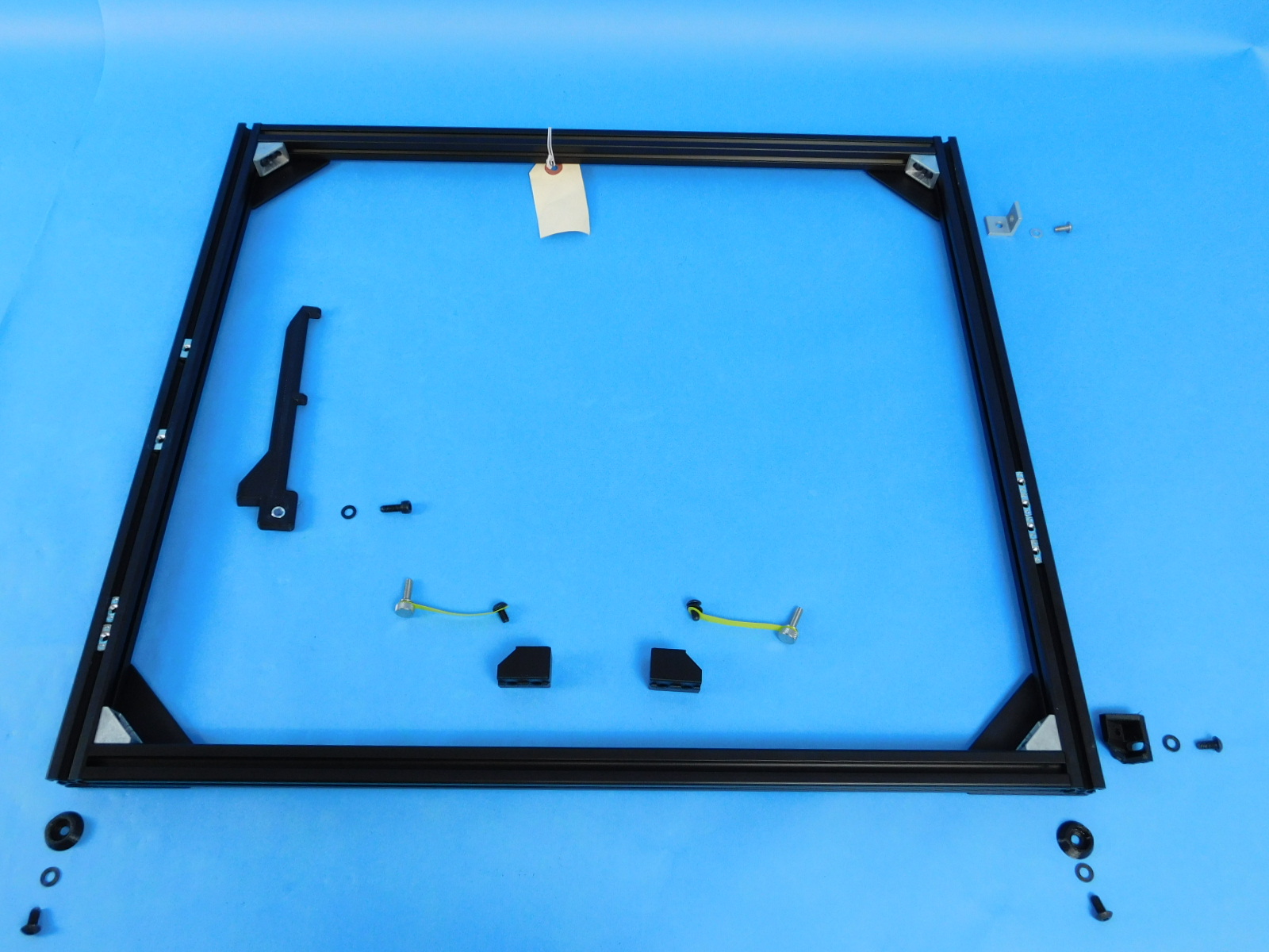
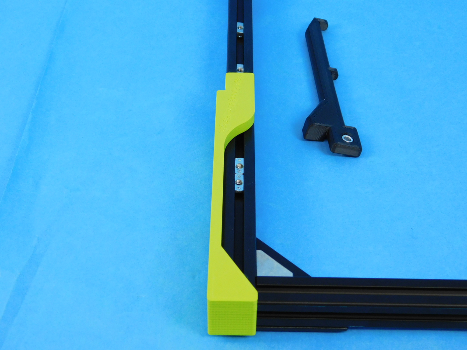
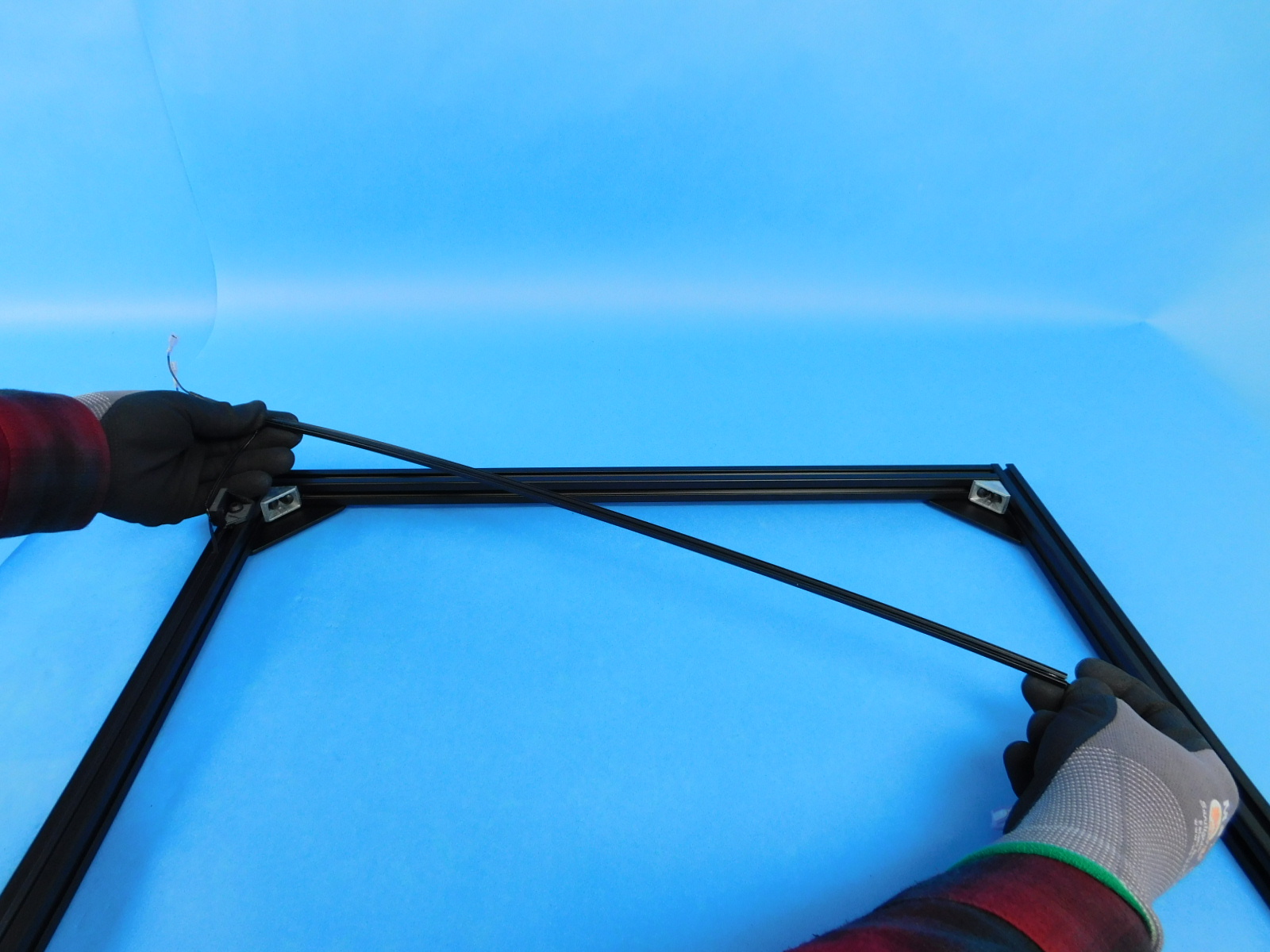
Place the t-nuts in the locations according to the drawing.
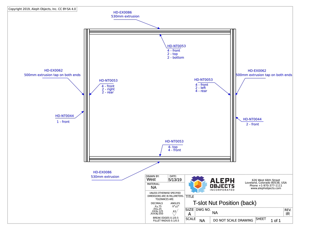
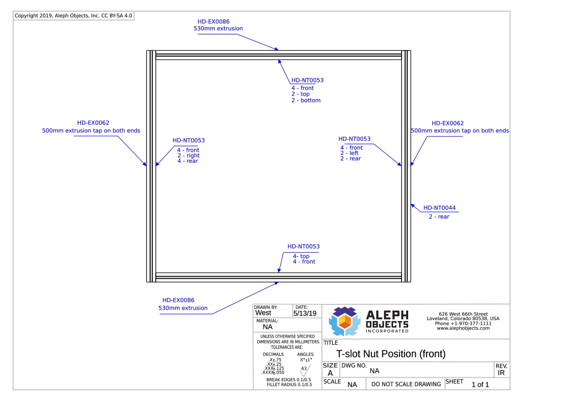
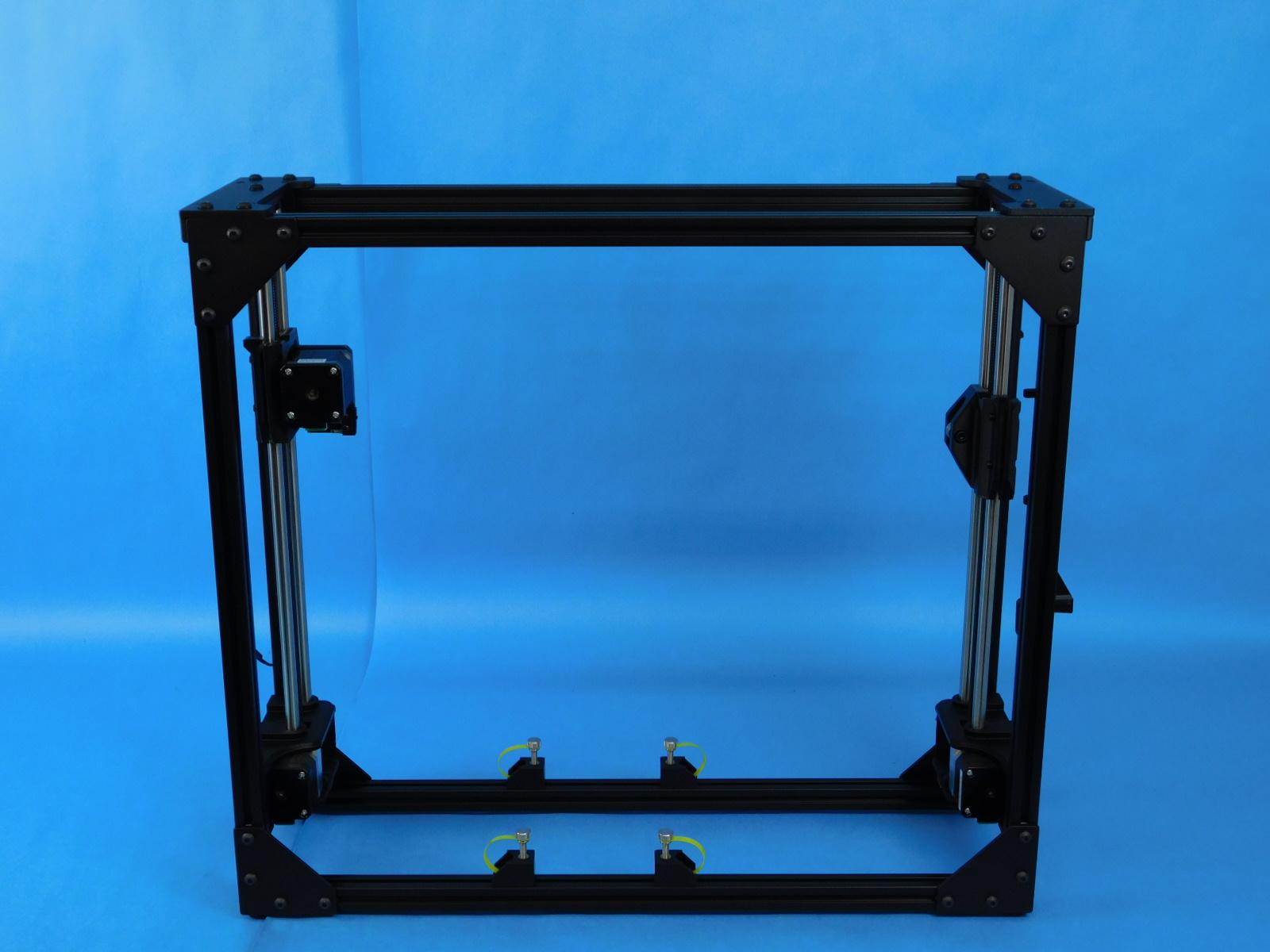
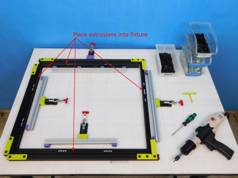
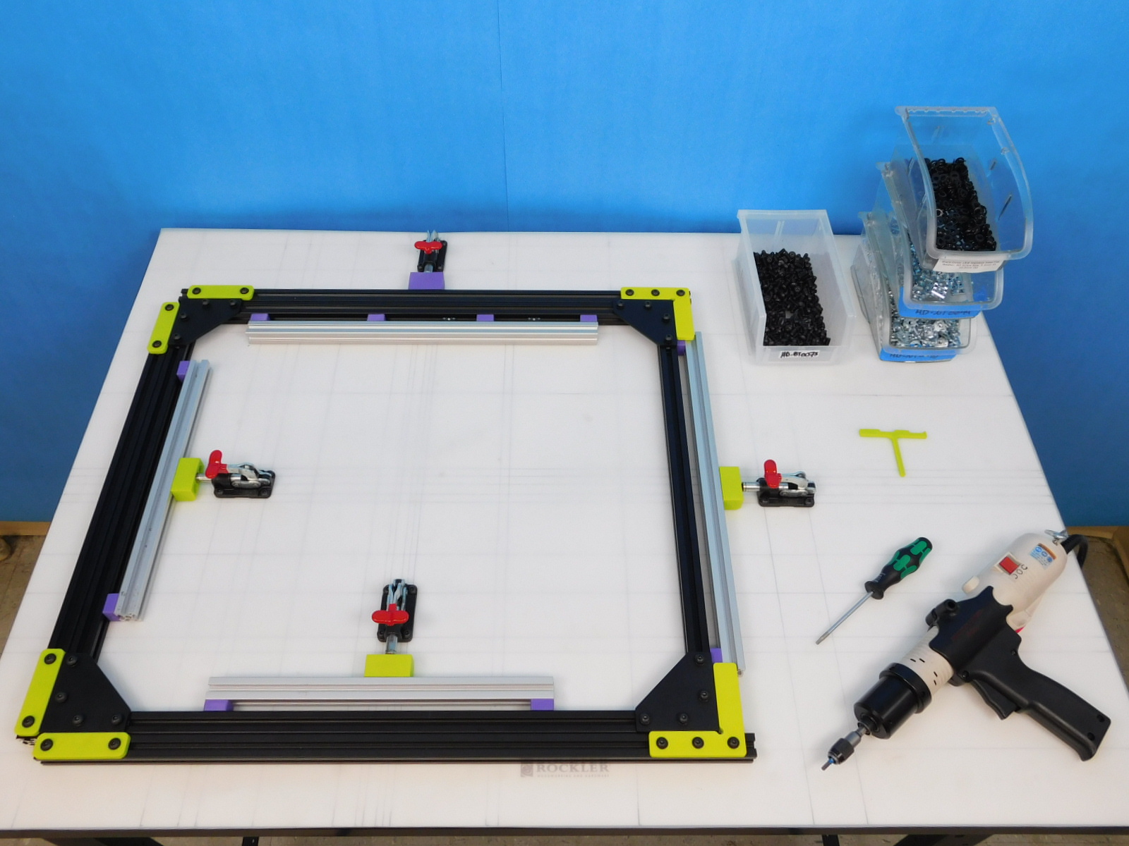
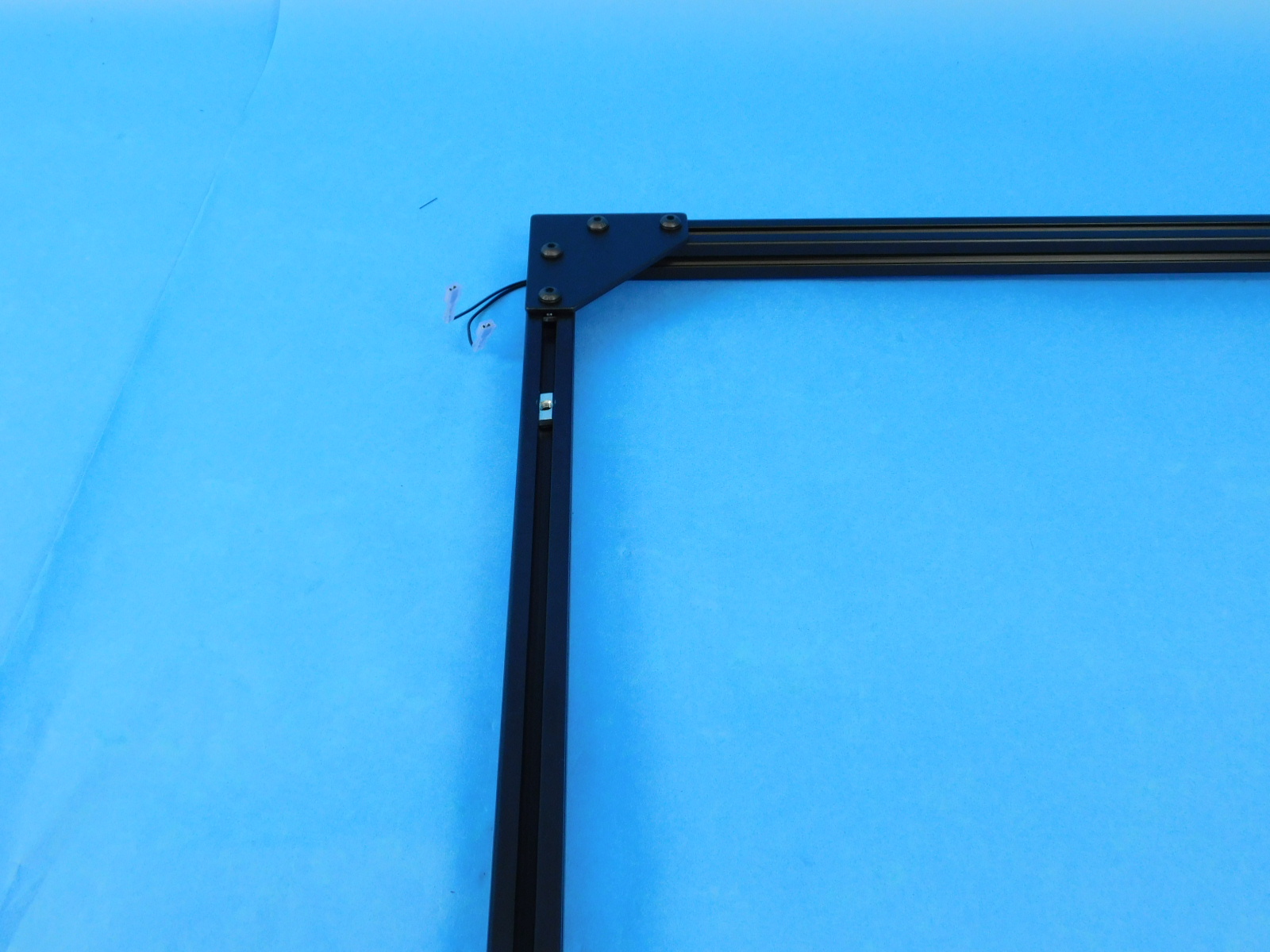
Place 2X [HD-EX0062] 500mm extrusions in the vertical slots and 2X [HD-EX0086] 530 extrusions in the horizontal slots.
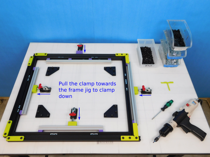
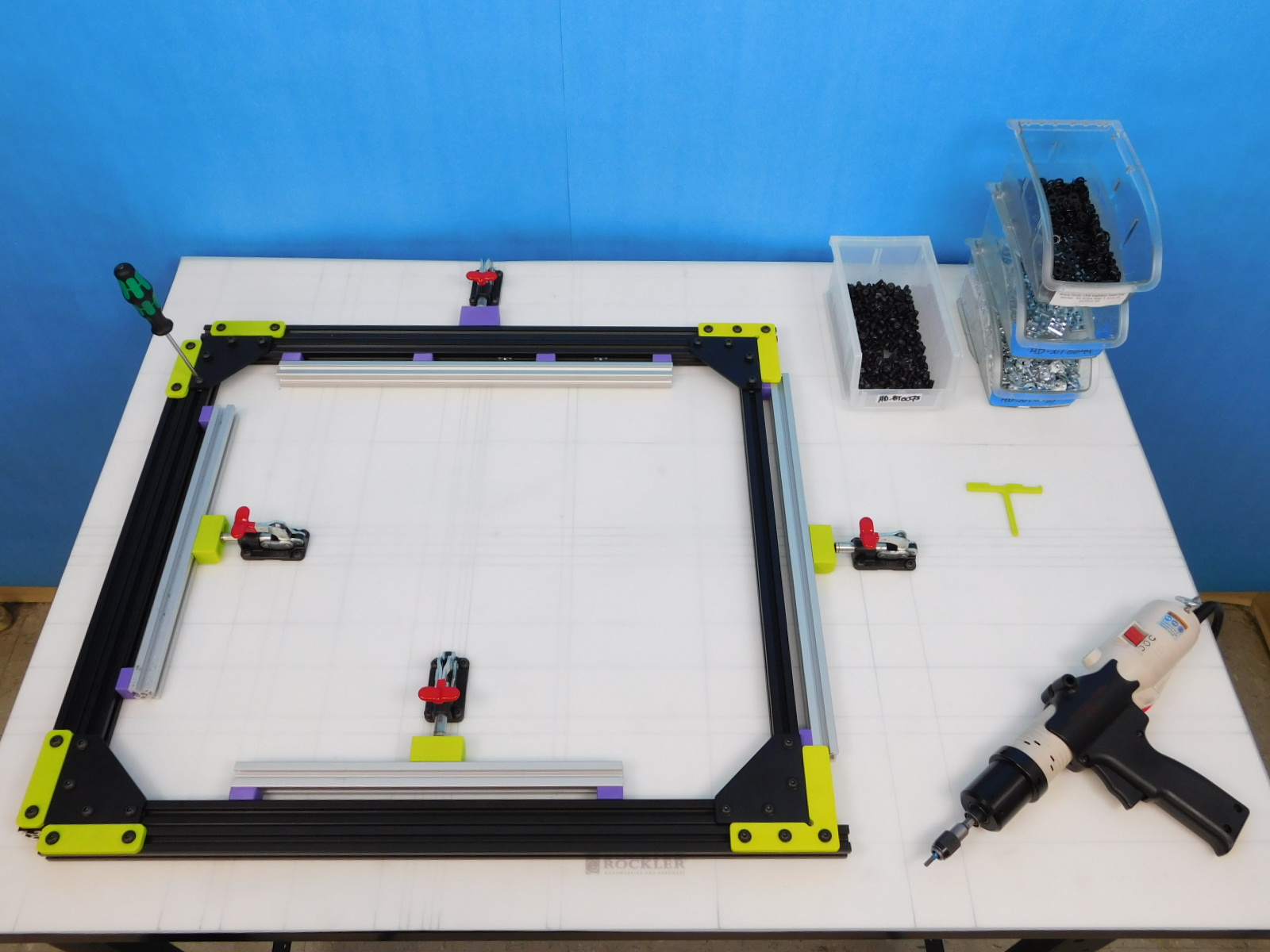
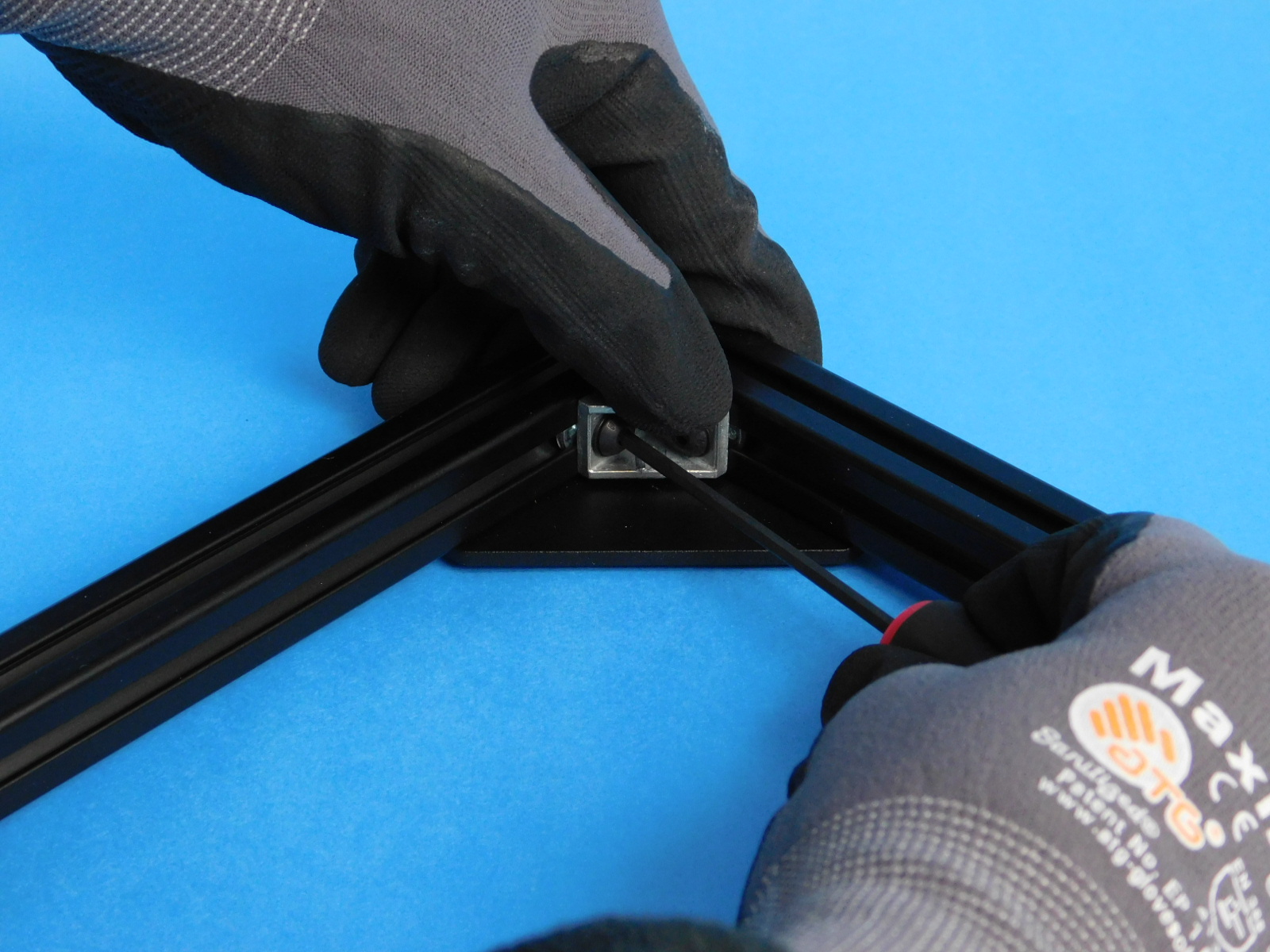
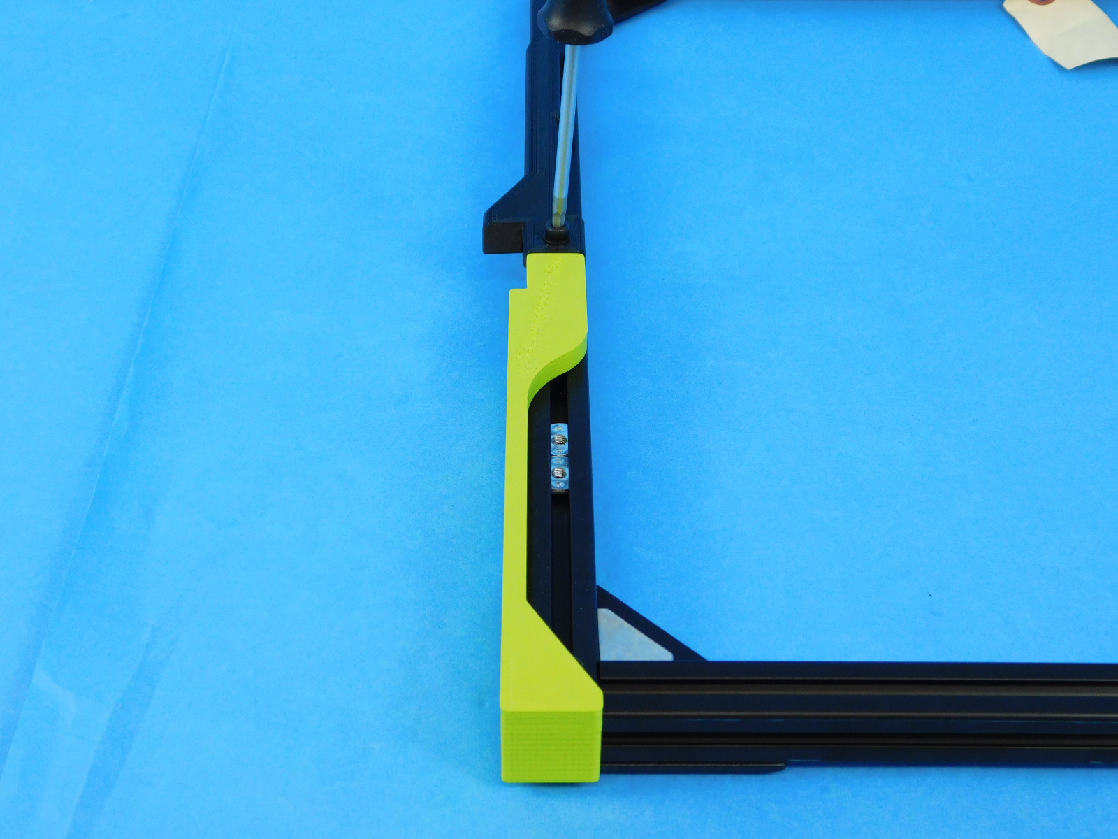
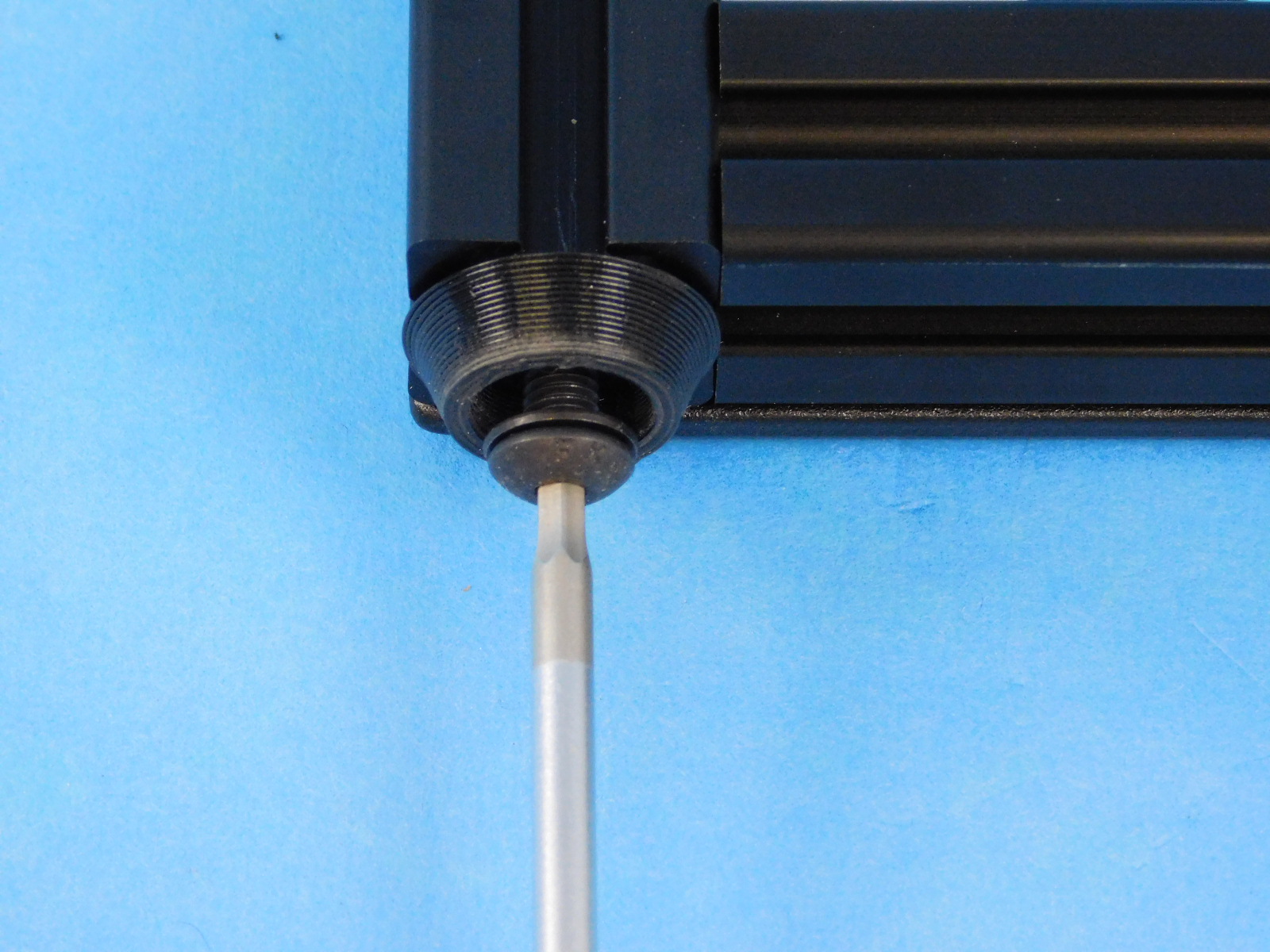
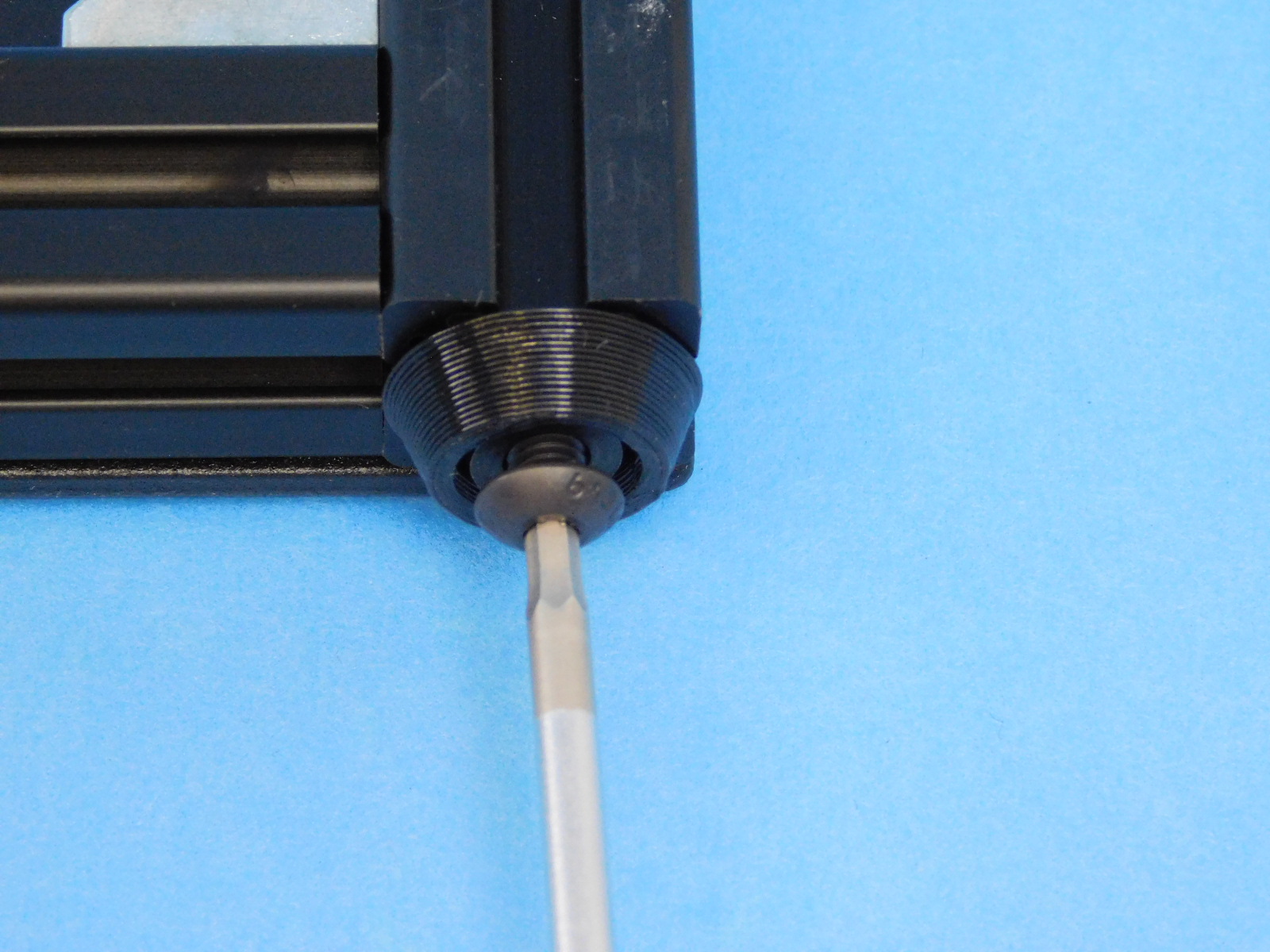
To clamp the frame into place, pull the handle towards the extrusions.
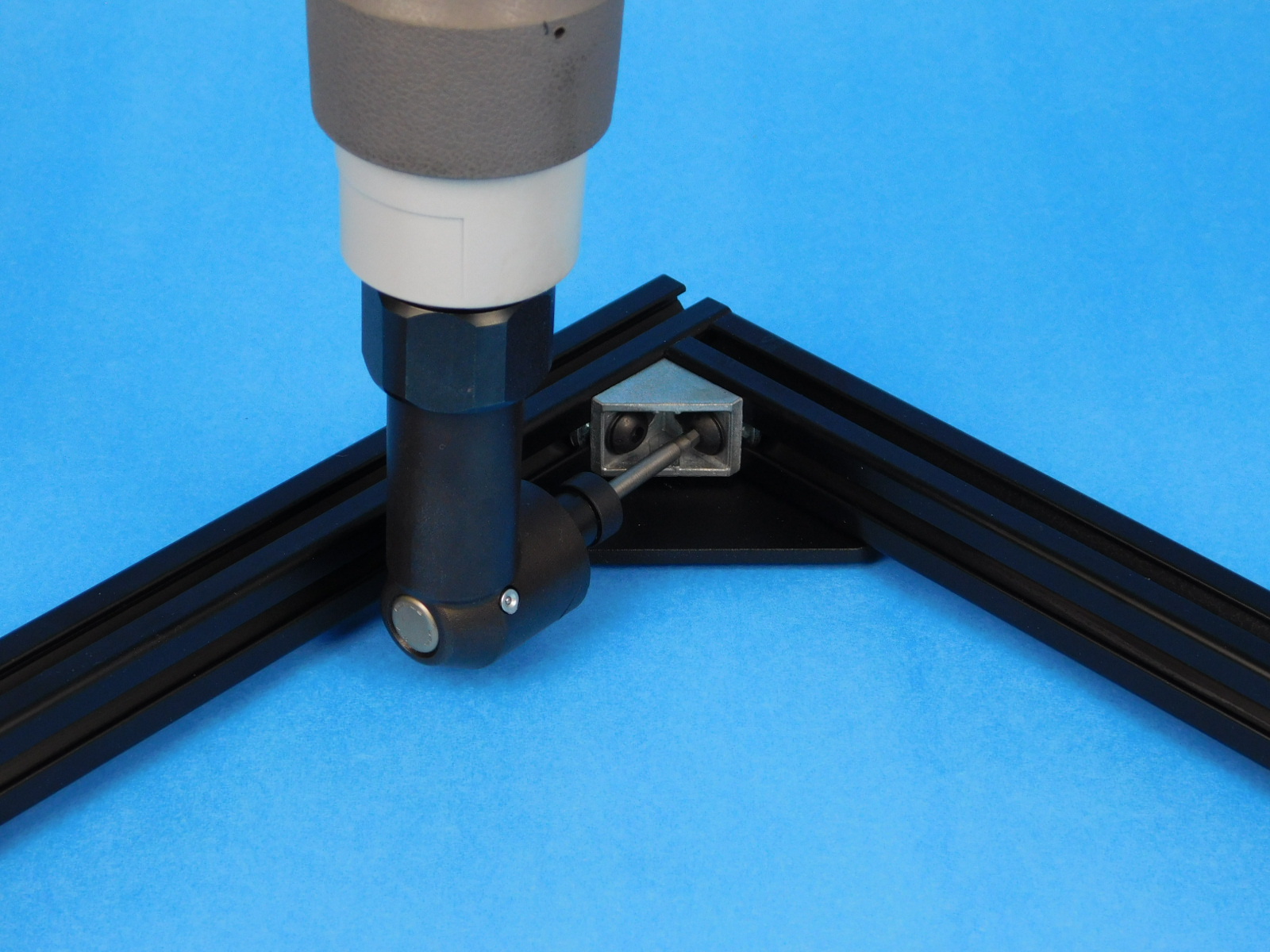
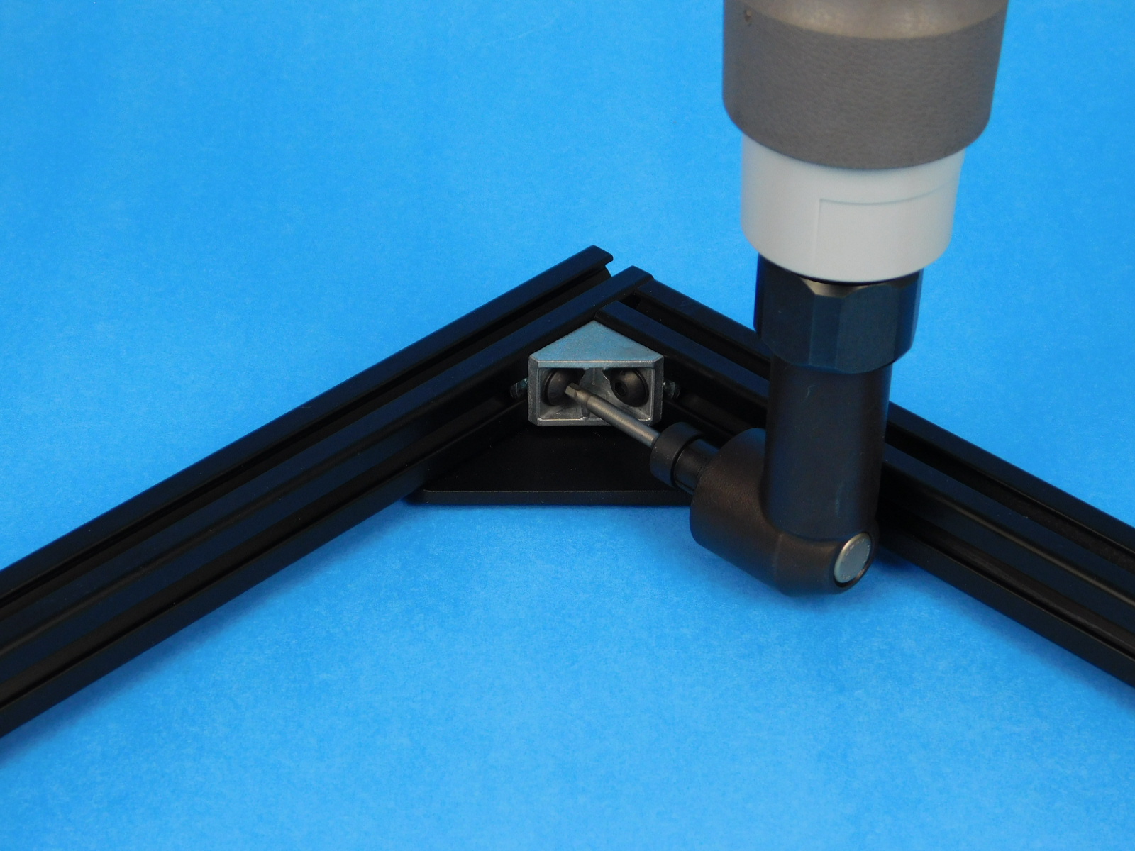
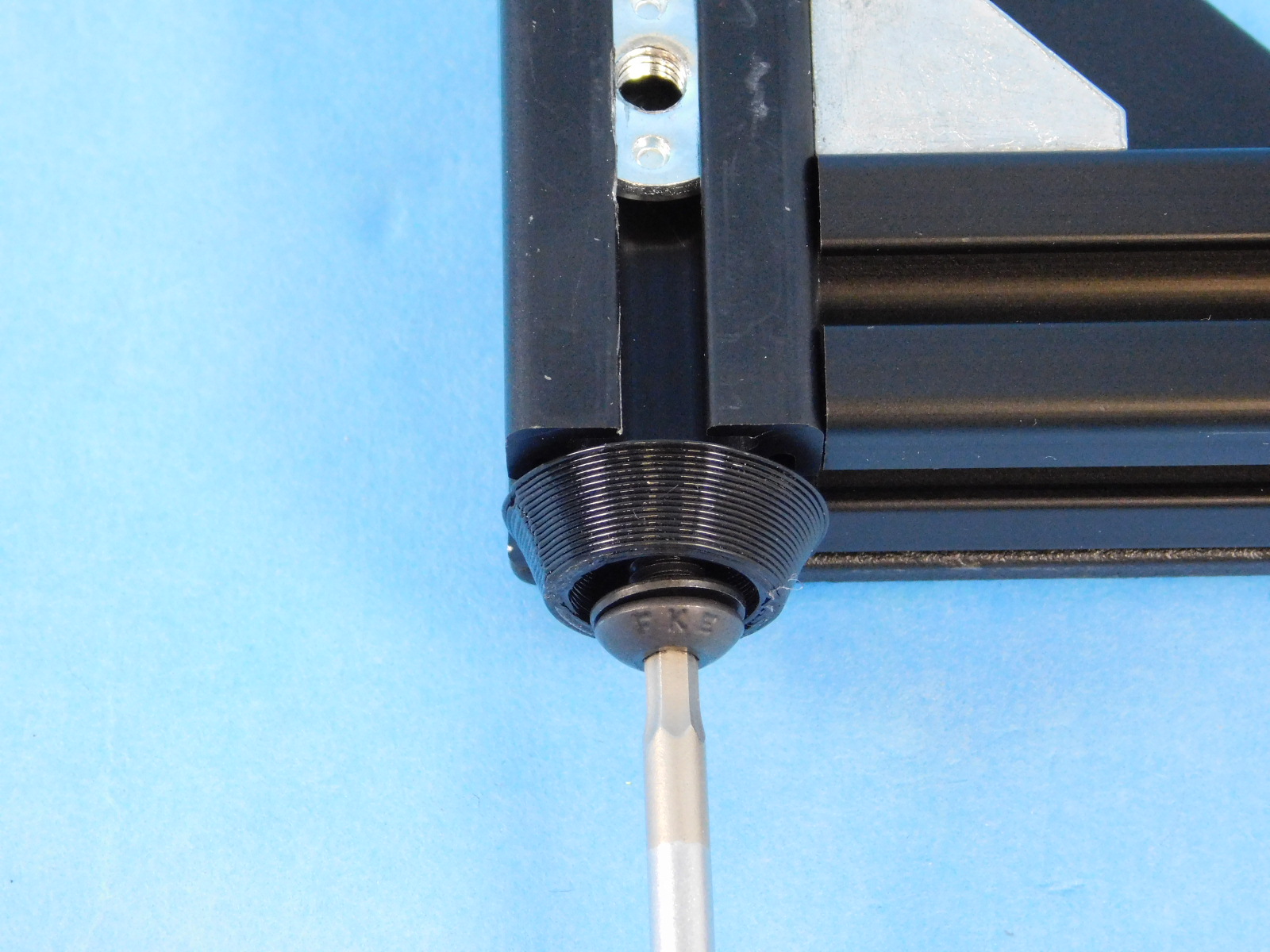
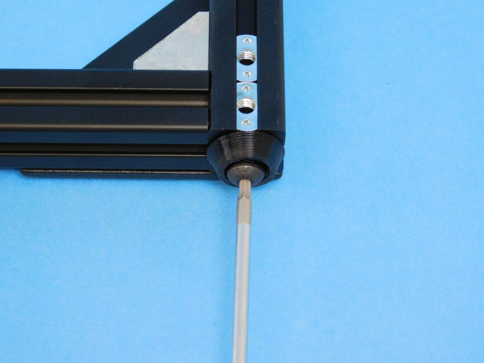
Utilize the t-nut alignment jig to align the t-nuts in preparation for installing the [PP-FP0152] frame corners.
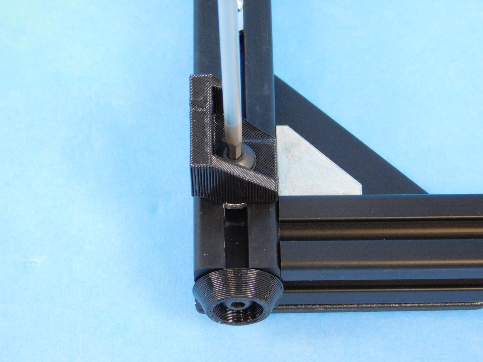
Align the 4X [PP-FP0152] frame corners with the t-slot nuts on each corner.
Fasten each [HD-FP0152] frame corner to the frame by hand, using 16X [HD-BT0073] M5X10 BHC fasteners.
Torque each [HD-BT0073] M5X10 BHC fastener to 40 in*lbs.
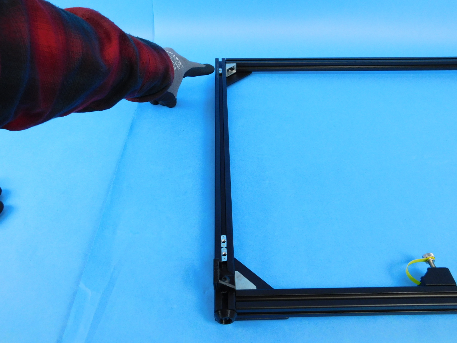
Remove the frame from the jig and repeat for the back face of the final assembly.
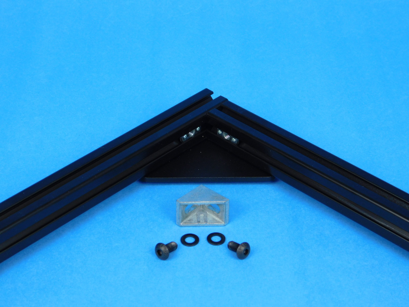
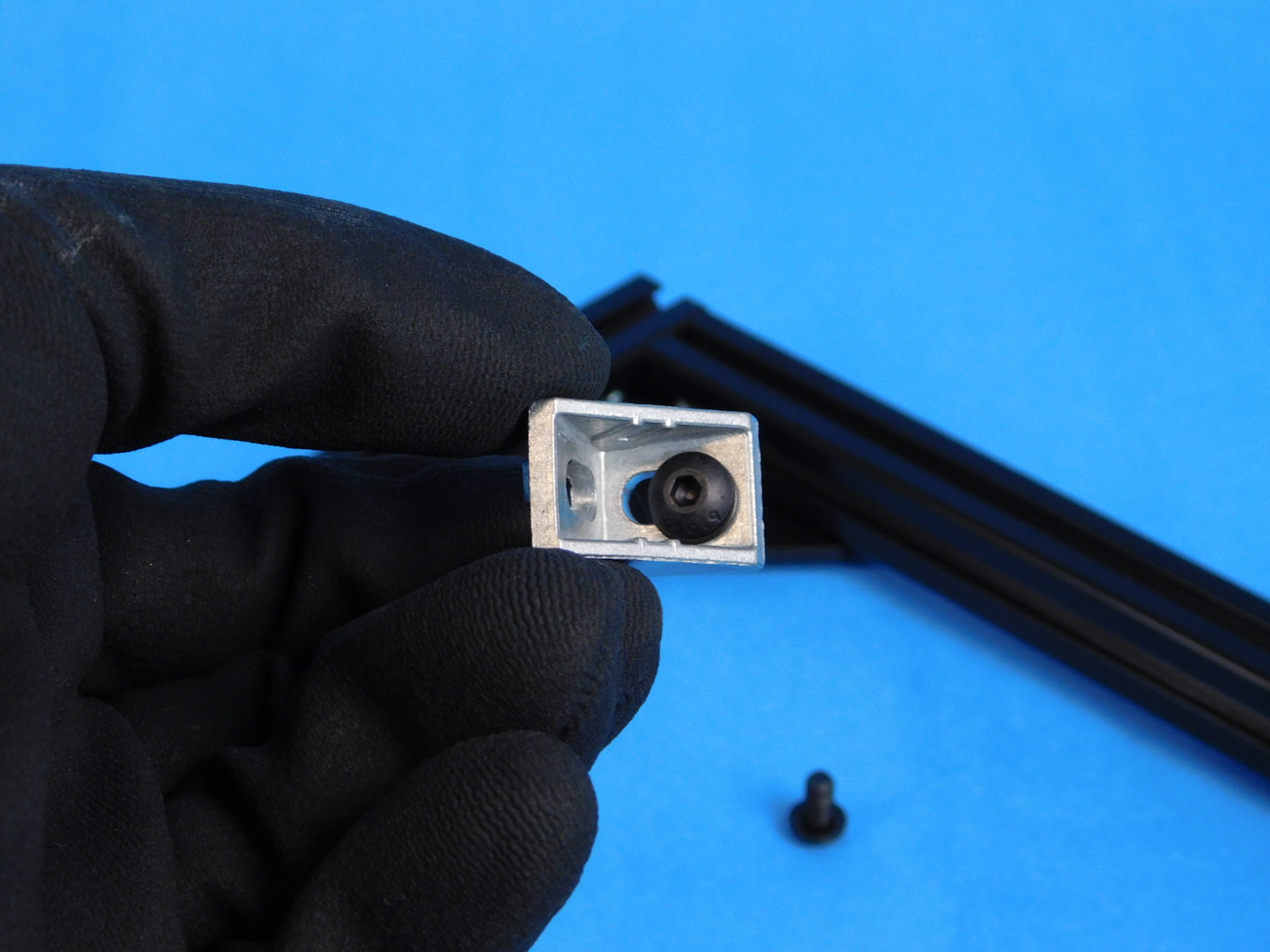
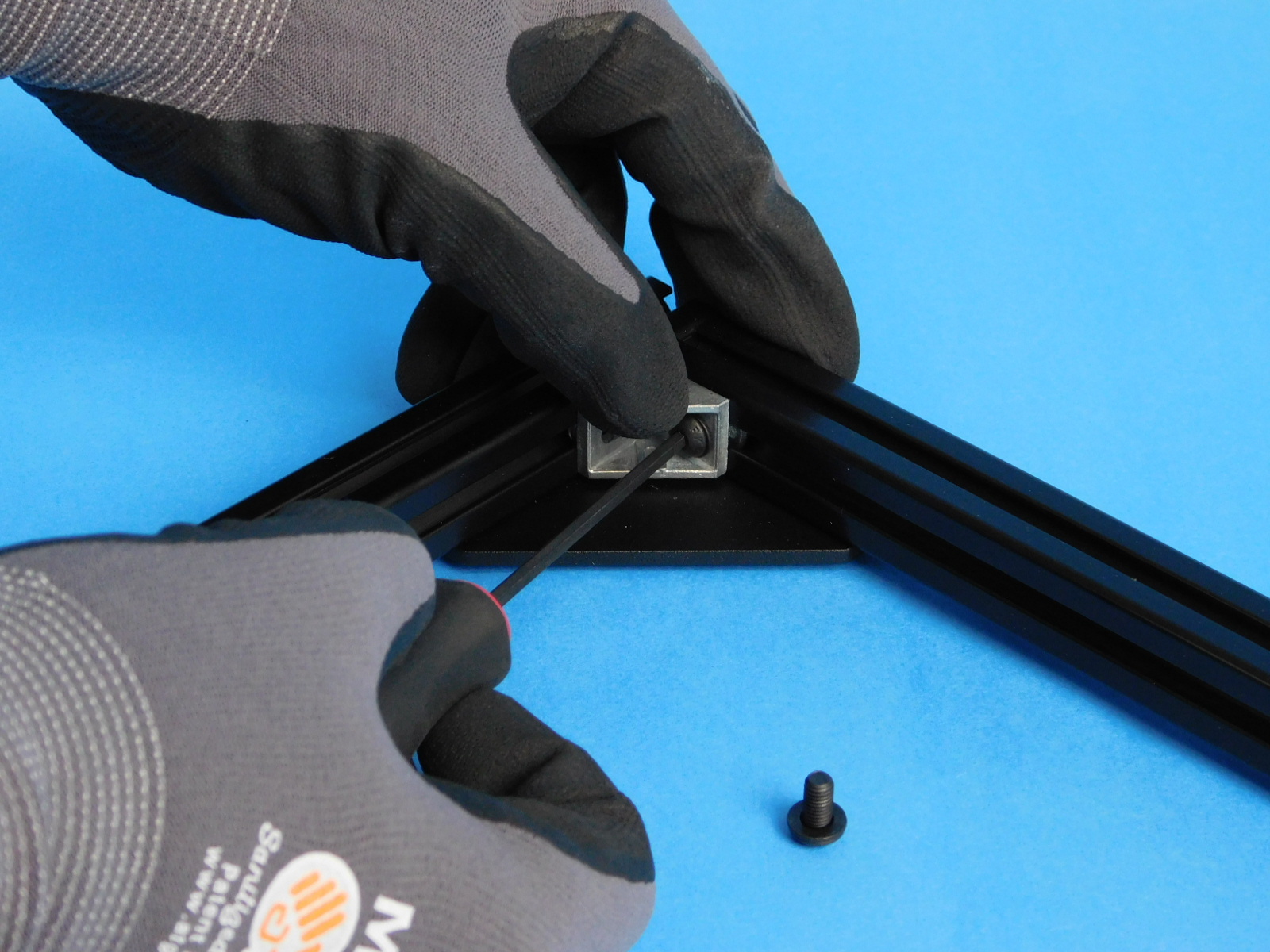
Take one 90 degree corner bracket [HD-EX0090], two M5 x 10 BHCS [HD-BT0073] and two M5 washers [HD-WA0040]. Attach one to each inside corner of the front and rear frame as shown.
Using two [HD-BT0073] M5x10 BHCS and two [HD-WA0040] M5 black oxide washers, fasten the [PP-GP0409] frame feet to the threaded holes in the bottom of the frame assembly.
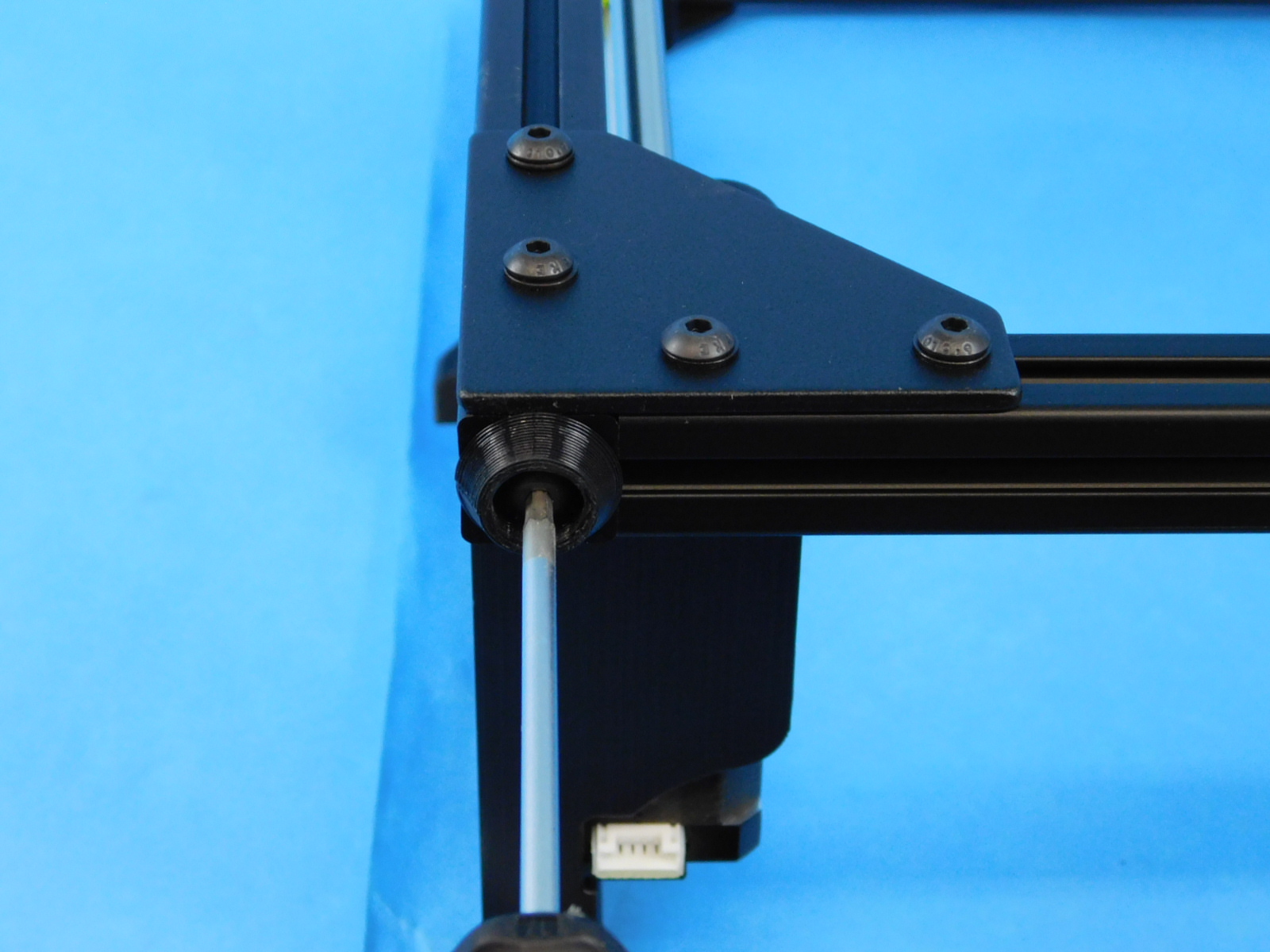
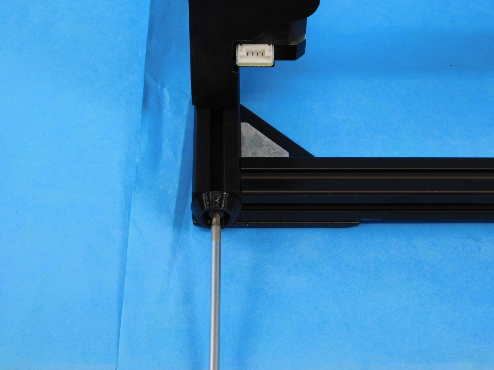
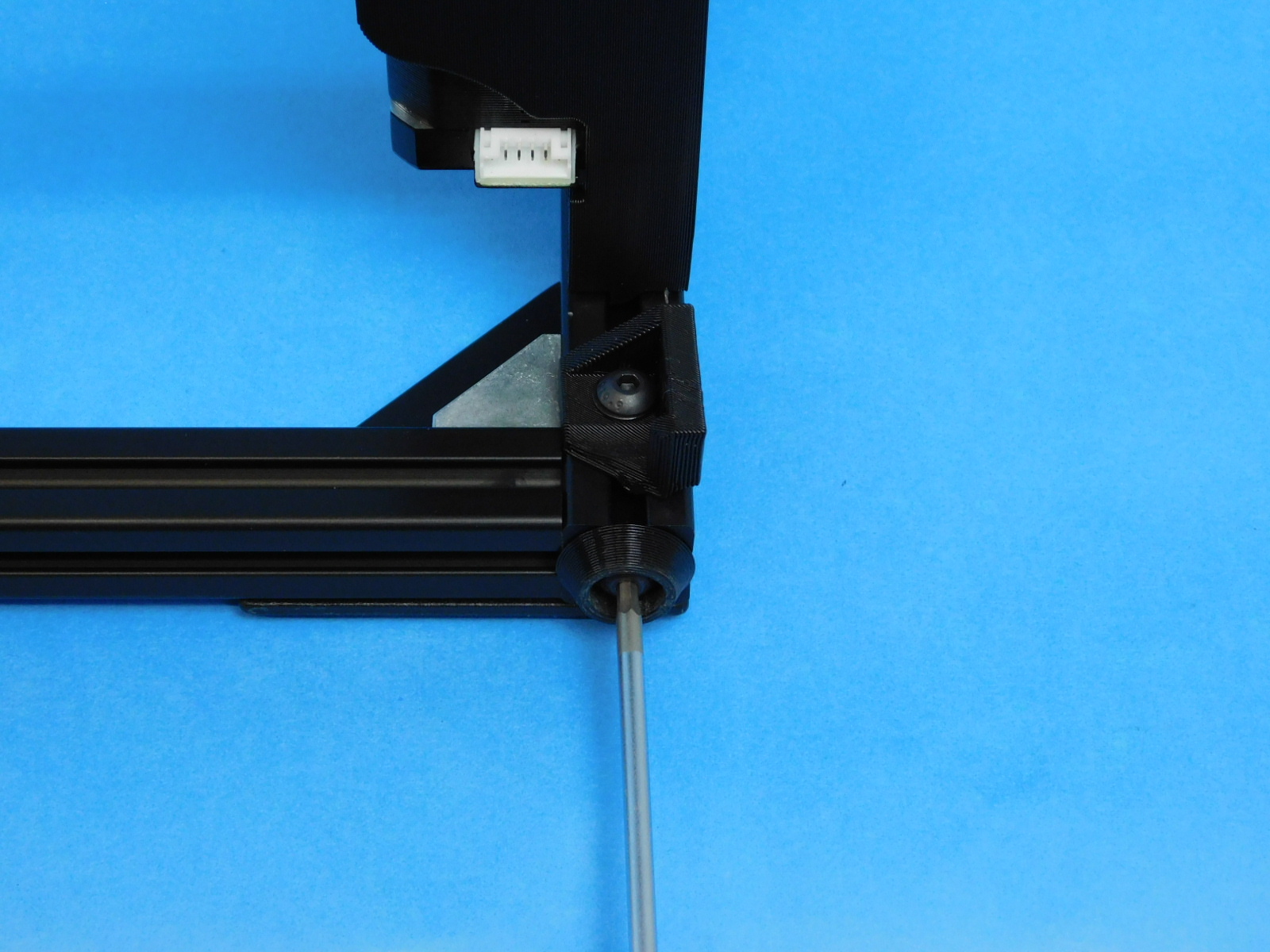
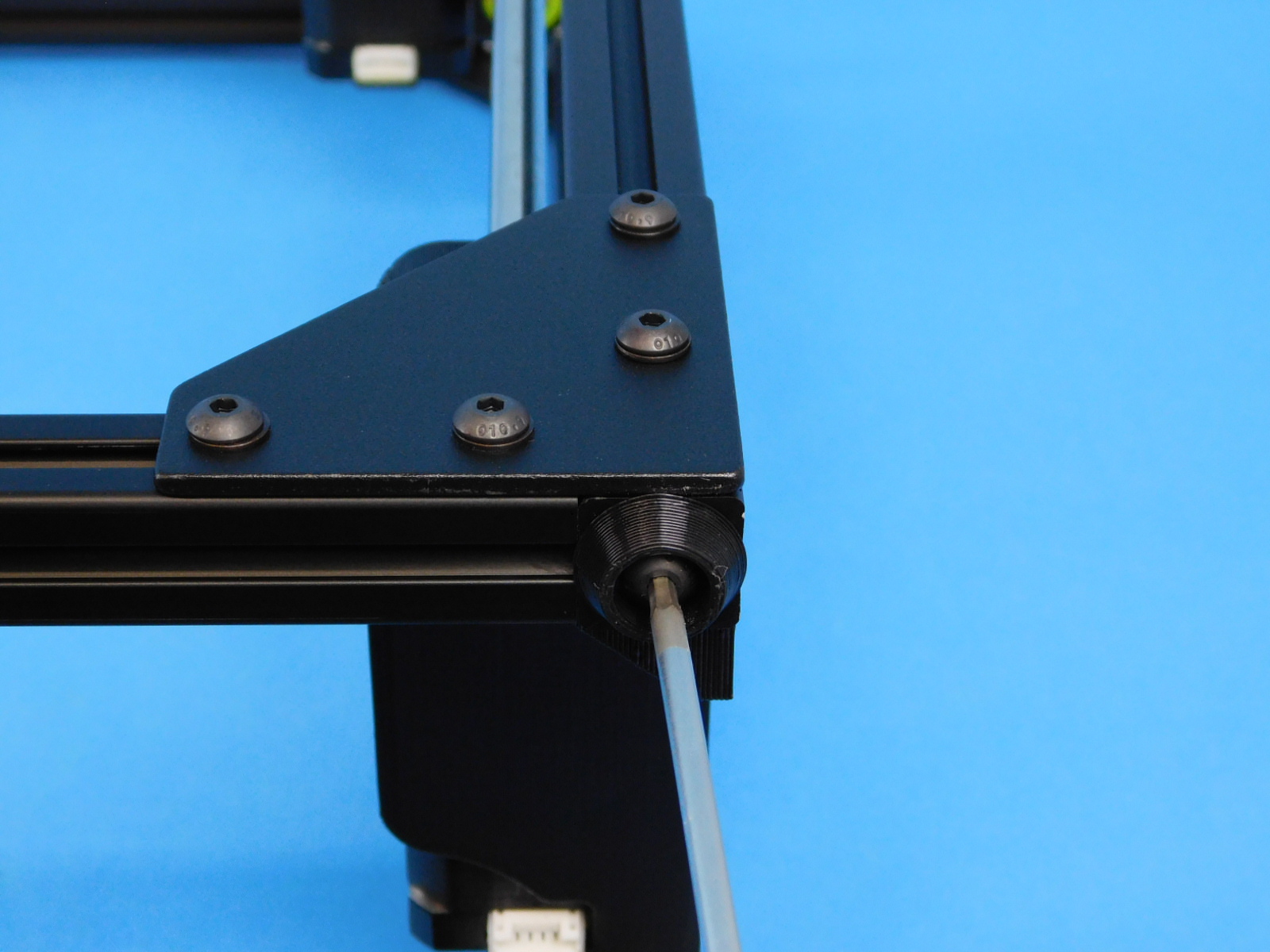
Using one [HD-BT0049] M5x14 SHCS and one [HD-WA0040] M5 black oxide washer, fasten the [AS-PR0137] spool arm assembly to the post assembly nut on the photo left side of the frame. This can be left loose at this time.
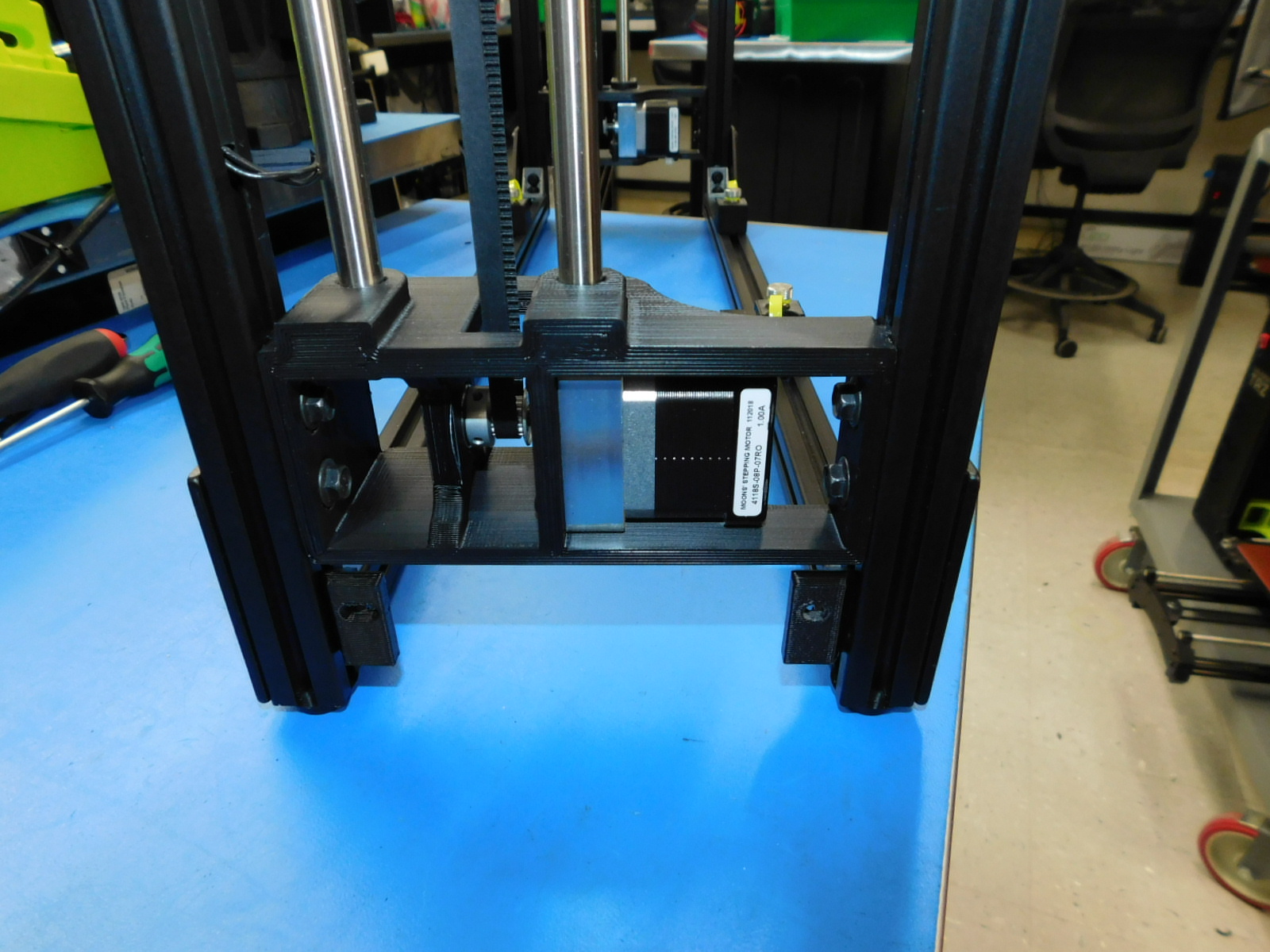
Using one [HD-BT0073] M5x10 BHCS and one [HD-WA0040] M5 black oxide washer, fasten the [PP-GP0410] front electronics chassis mount to bottom most t-slot nut on the photo right side of the frame.
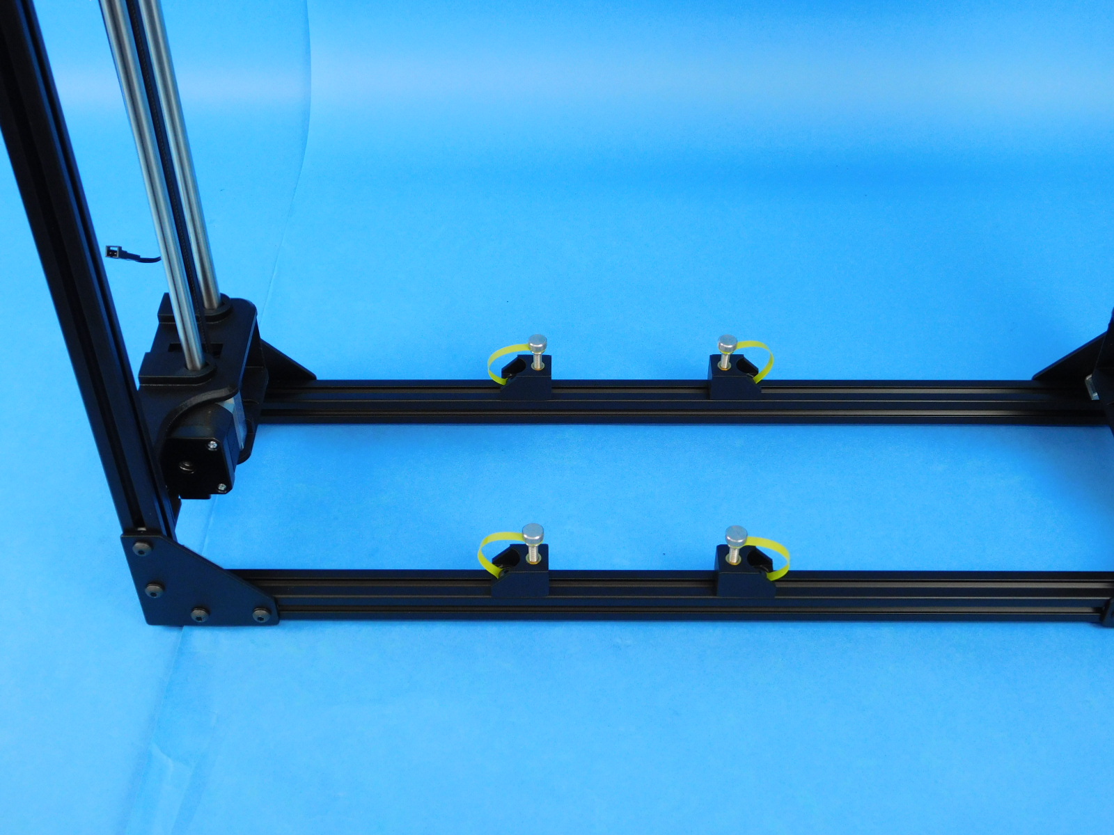
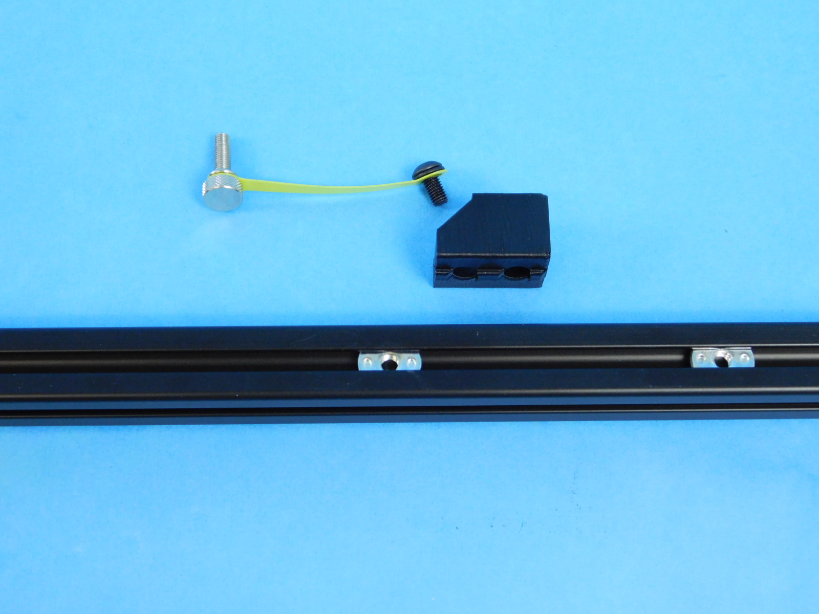
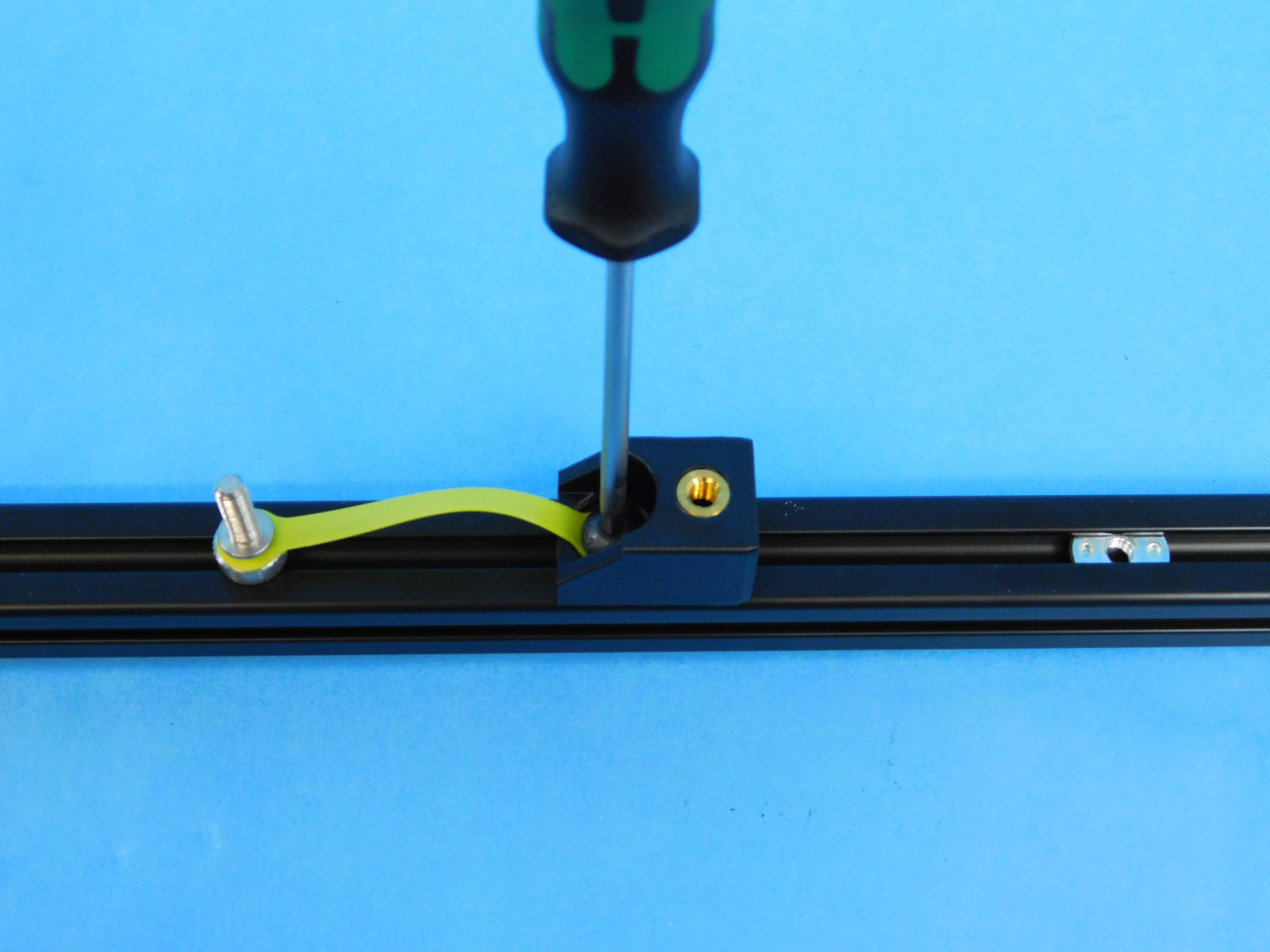
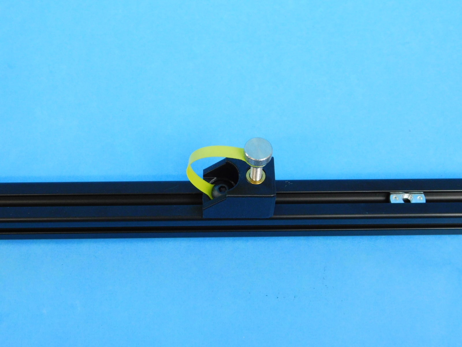
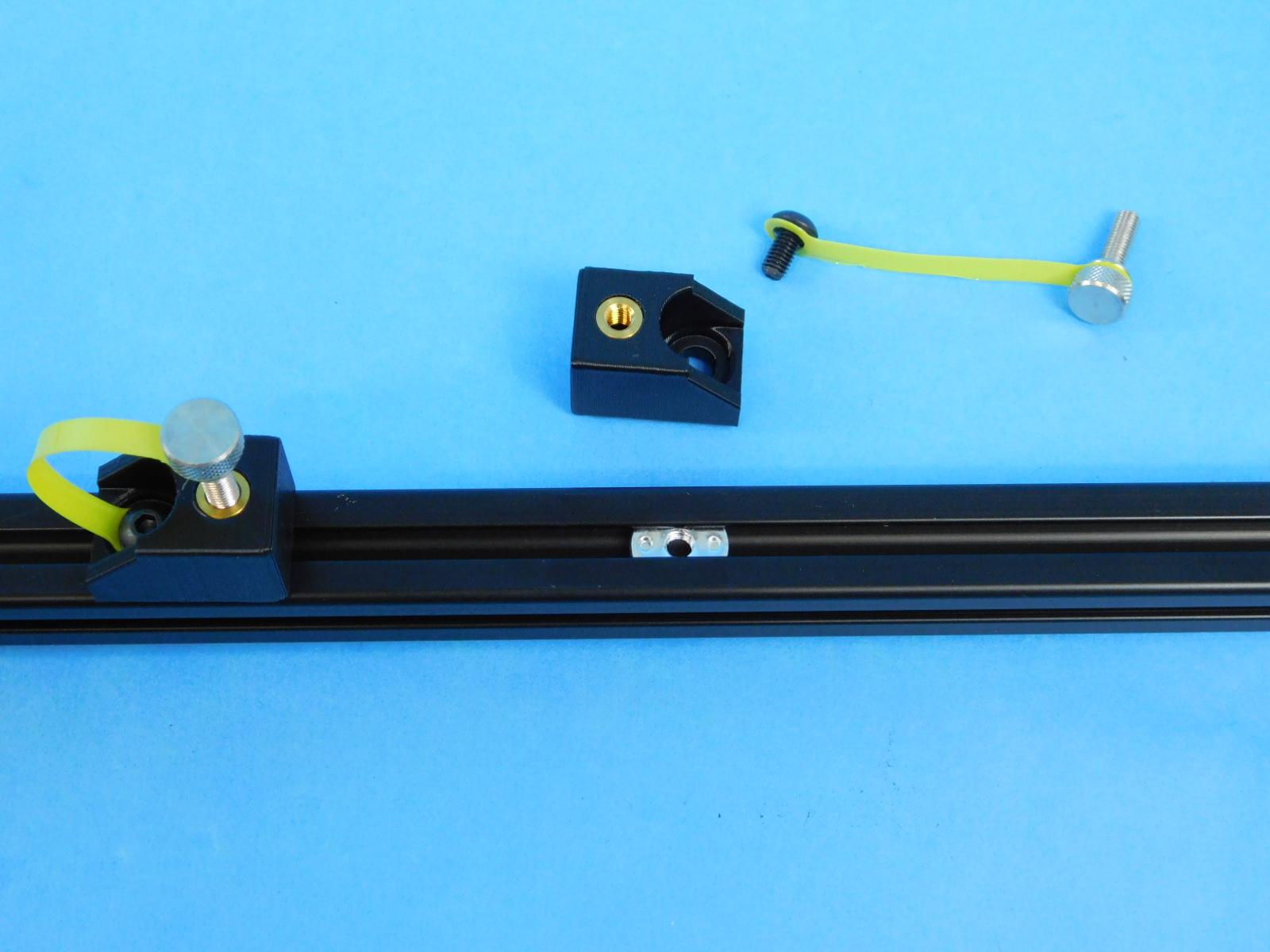
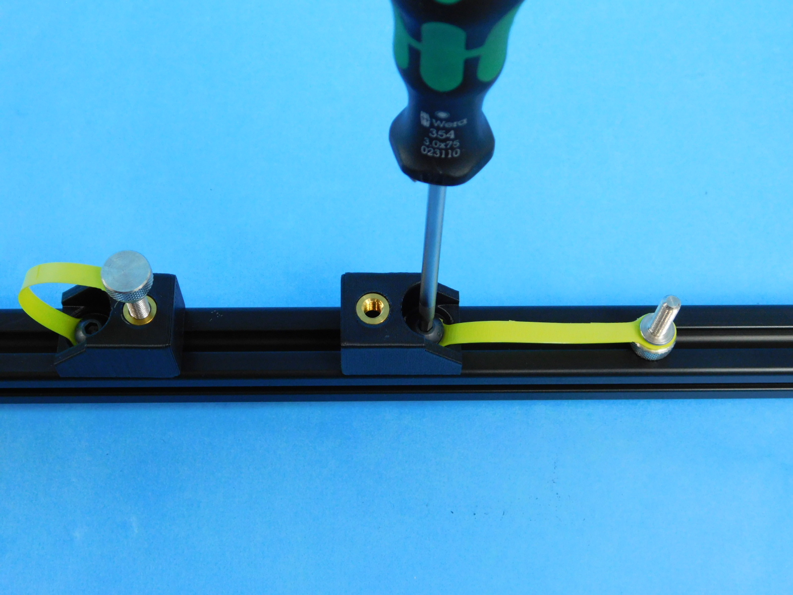
Use two [HD-BT0158] M5 x 12 BHCS and two [HD-WA0040] M5 washers, attach the [PP-IS0098] Y-Mount Chassis to the frame along with two Thumbscrews [HD-BT0554] with Leashes [PP-GP0448].
The screw used mounting the Y Mount Chassis should be fed through the end of the thumbscrew leash facing the opposite direction of the thumbscrew before being attached to the frame.
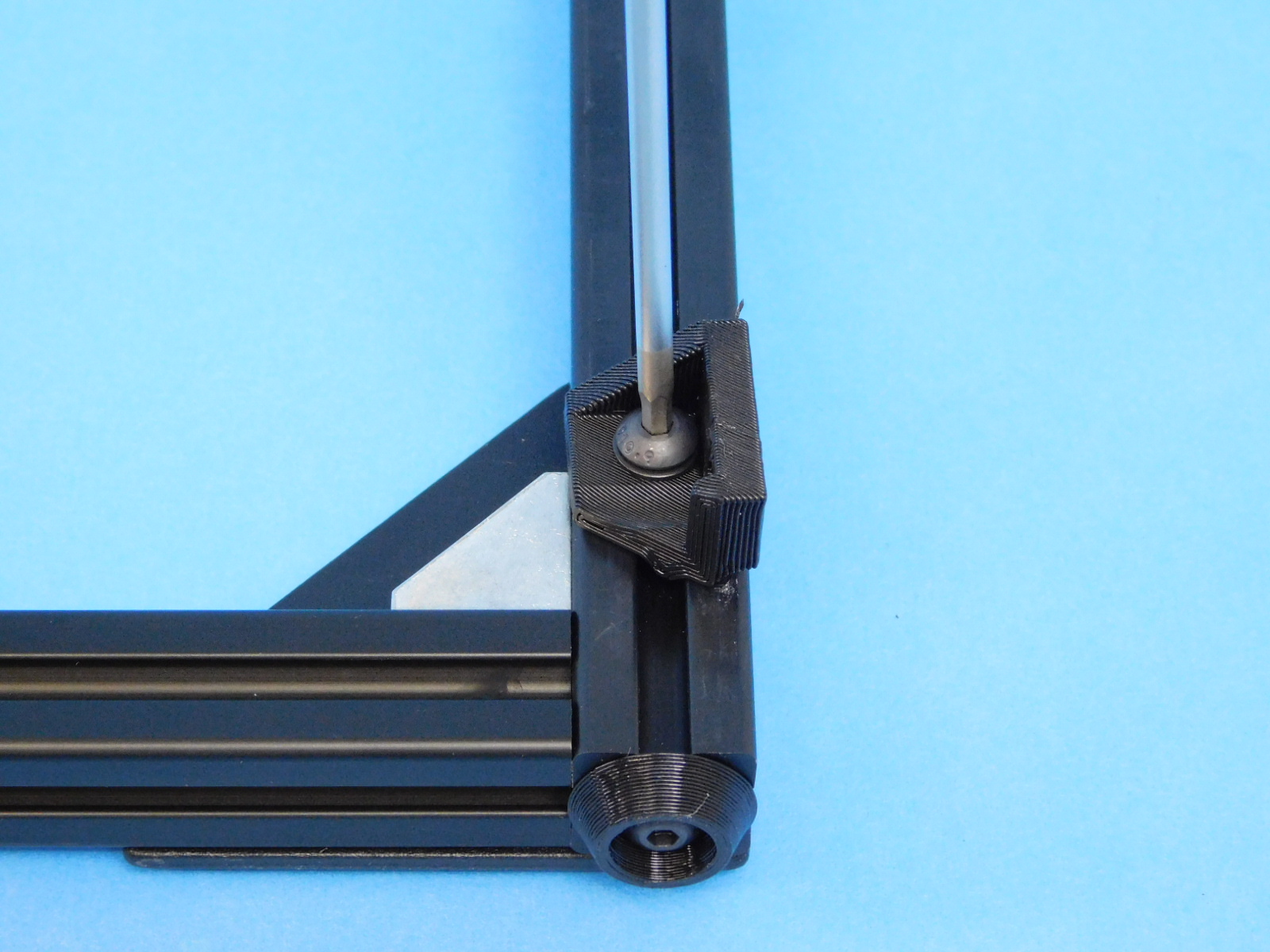
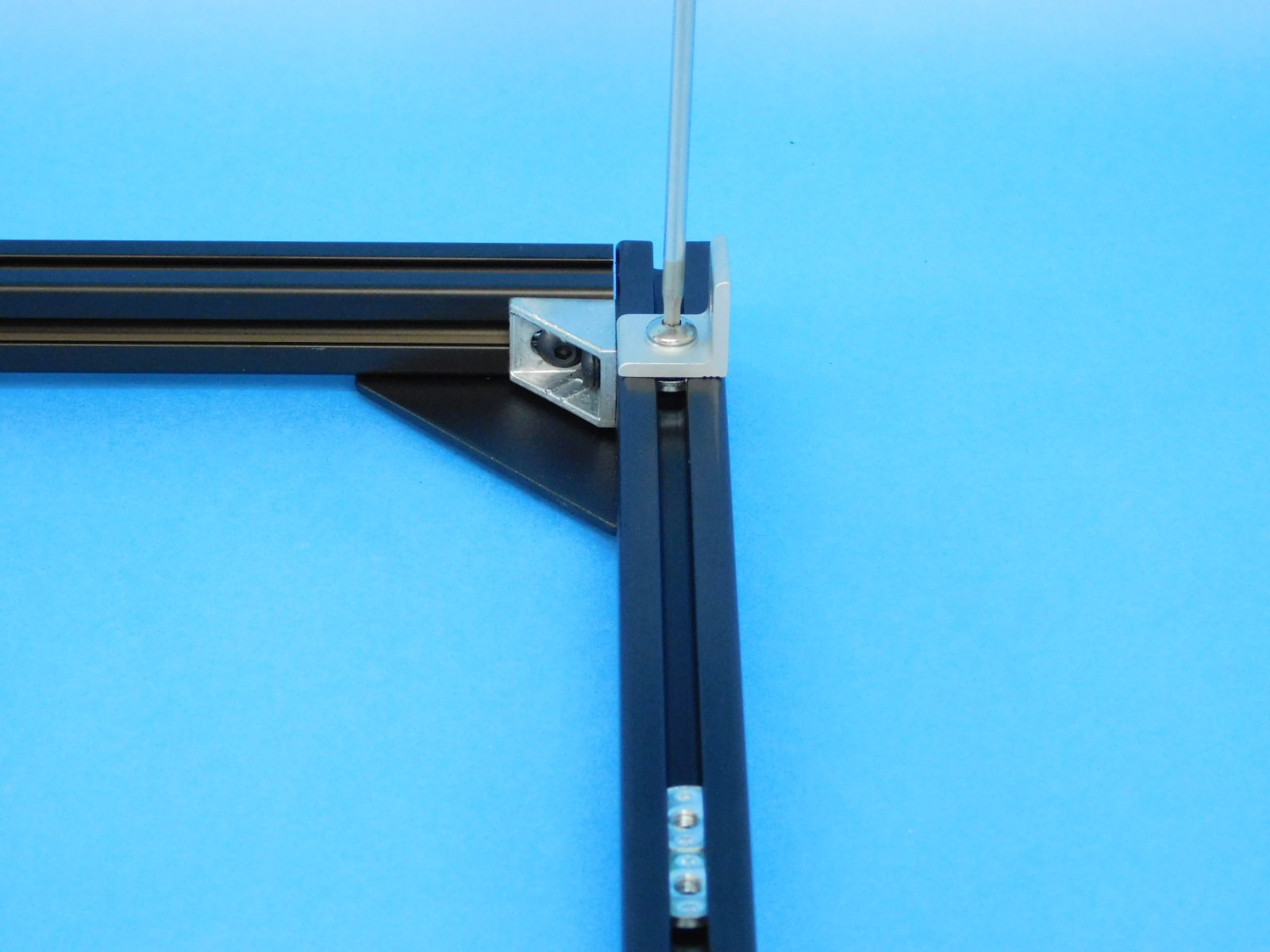
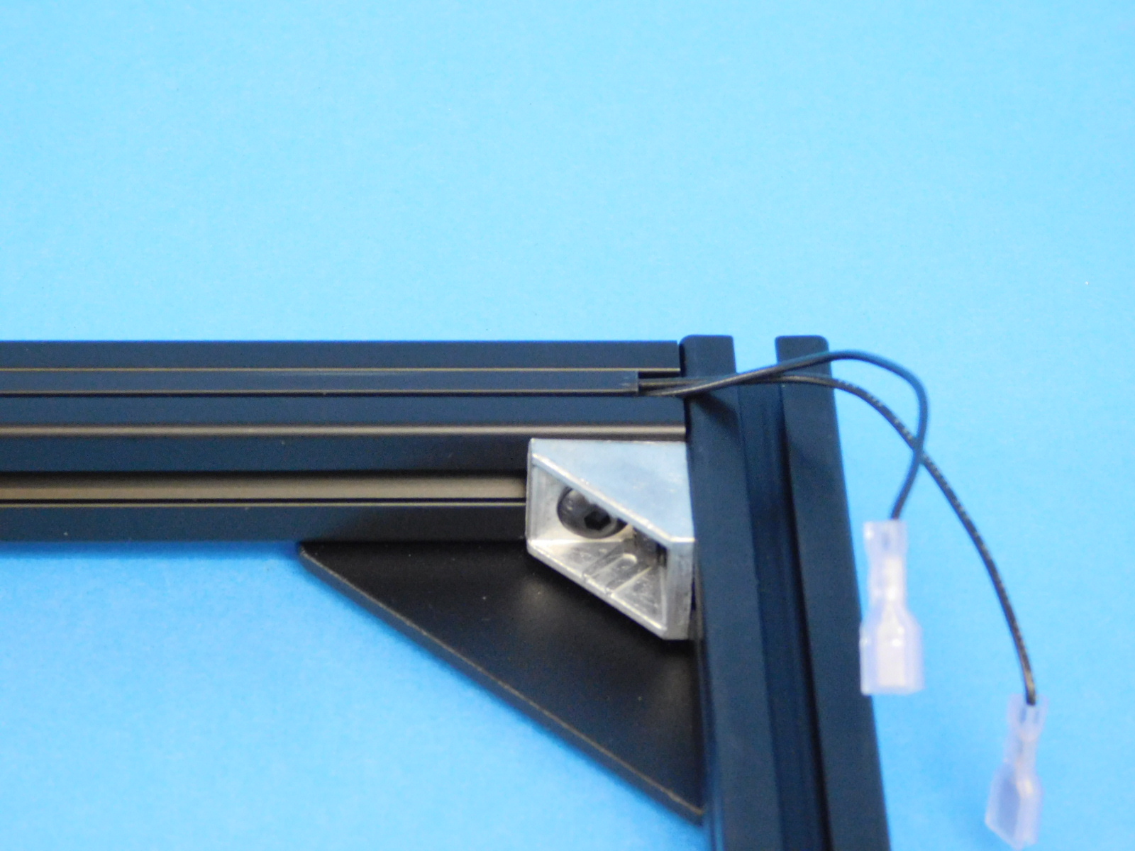
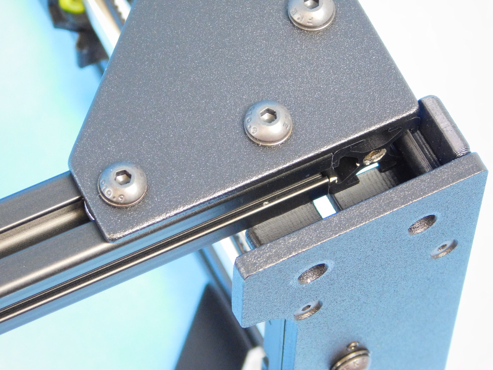
Using one [HD-BT0225] M5x10 stainless steel BHCS and one [HD-WA0007] M5 stainless washer, fasten the [HD-EX0092] aluminum corner bracket to the top most t-slot nut on the photo right side of the frame.


Using two [HD-BT0073] M5x10 BHCS and two [HD-WA0040] M5 black oxide washers, fasten the [PP-GP0409] frame feet to the threaded holes in the bottom of the frame assembly.
Using two [HD-BT0073] M5 x 10 BHCS and two [HD-WA0040] M5 washer, attach the [PP-GP0411] back chassis mount to the frame.
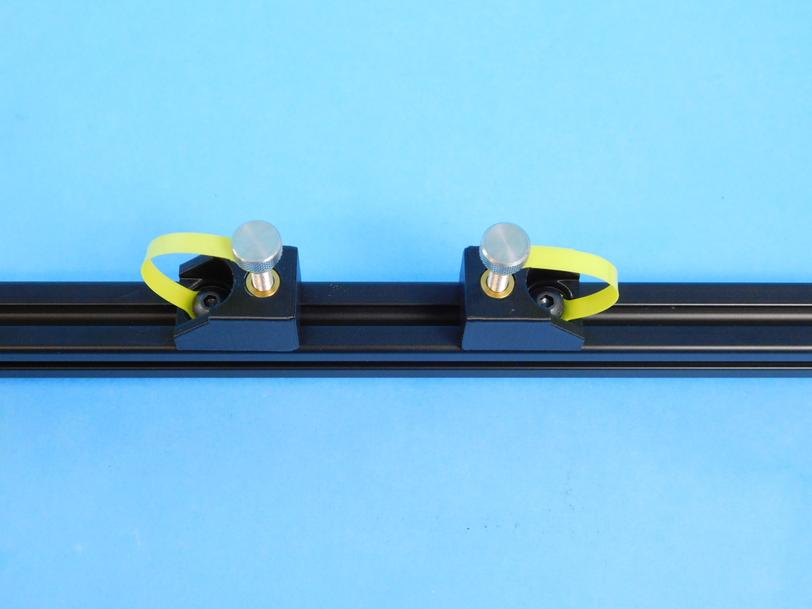
Use two [HD-BT0158] M5 x 12 BHCS and two [HD-WA0040] M5 washers, attach the [PP-IS0098] Y-Mount Chassis to the frame along with two Thumbscrews [HD-BT0554] with Leashes [PP-GP0448].
The screw used mounting the Y Mount Chassis should be fed through the end of the thumbscrew leash facing the opposite direction of the thumbscrew before being attached to the frame.
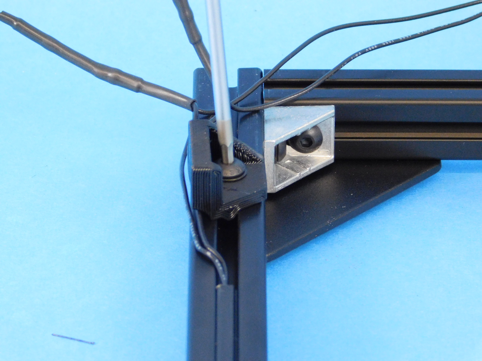
Use one [HD-BT0049] M5 x 14 SHCS and one [HD-WA0040] M5 washer, attach the feed tube holder [AS-PR0011] to rear frame as pictured.
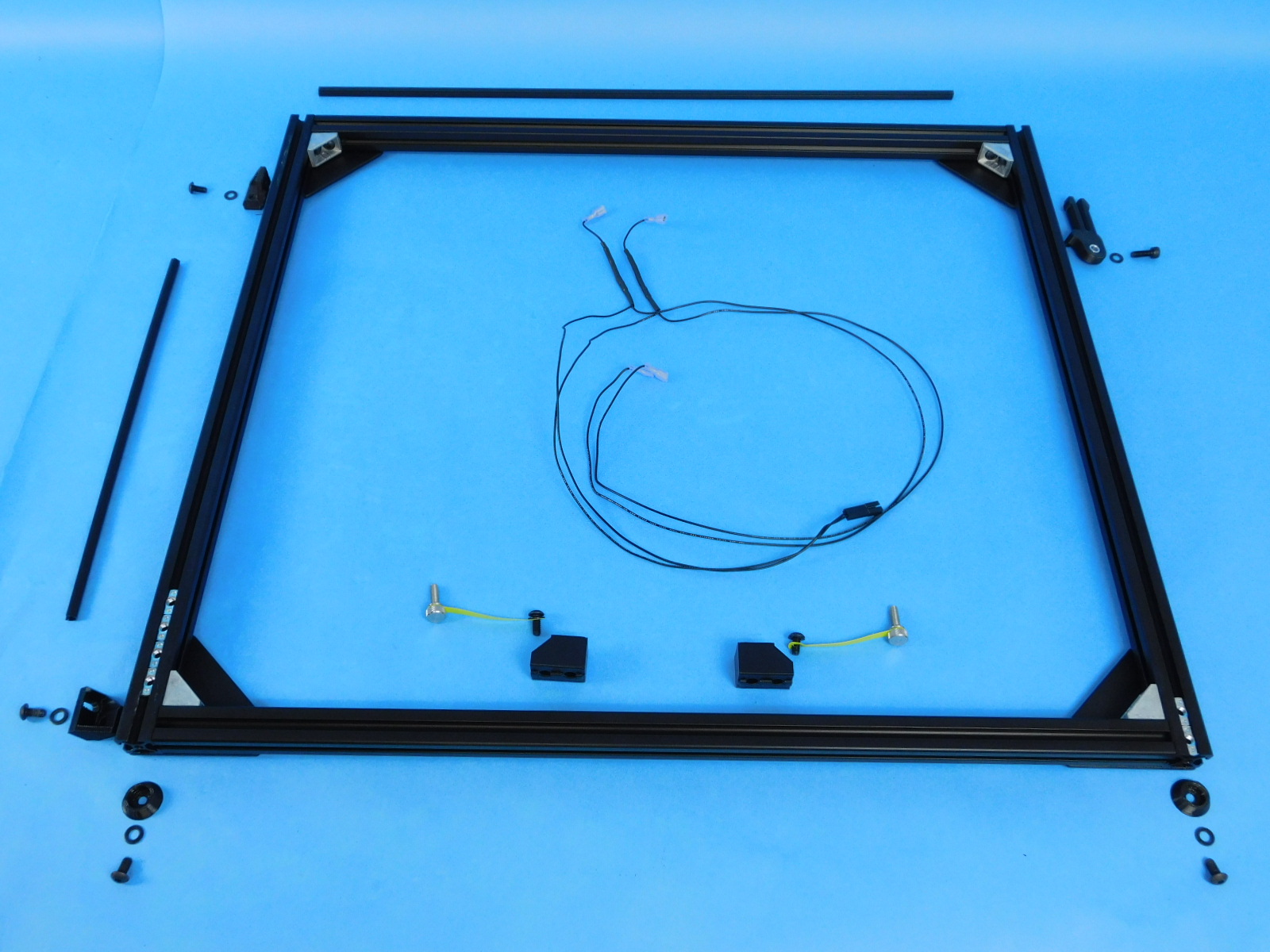
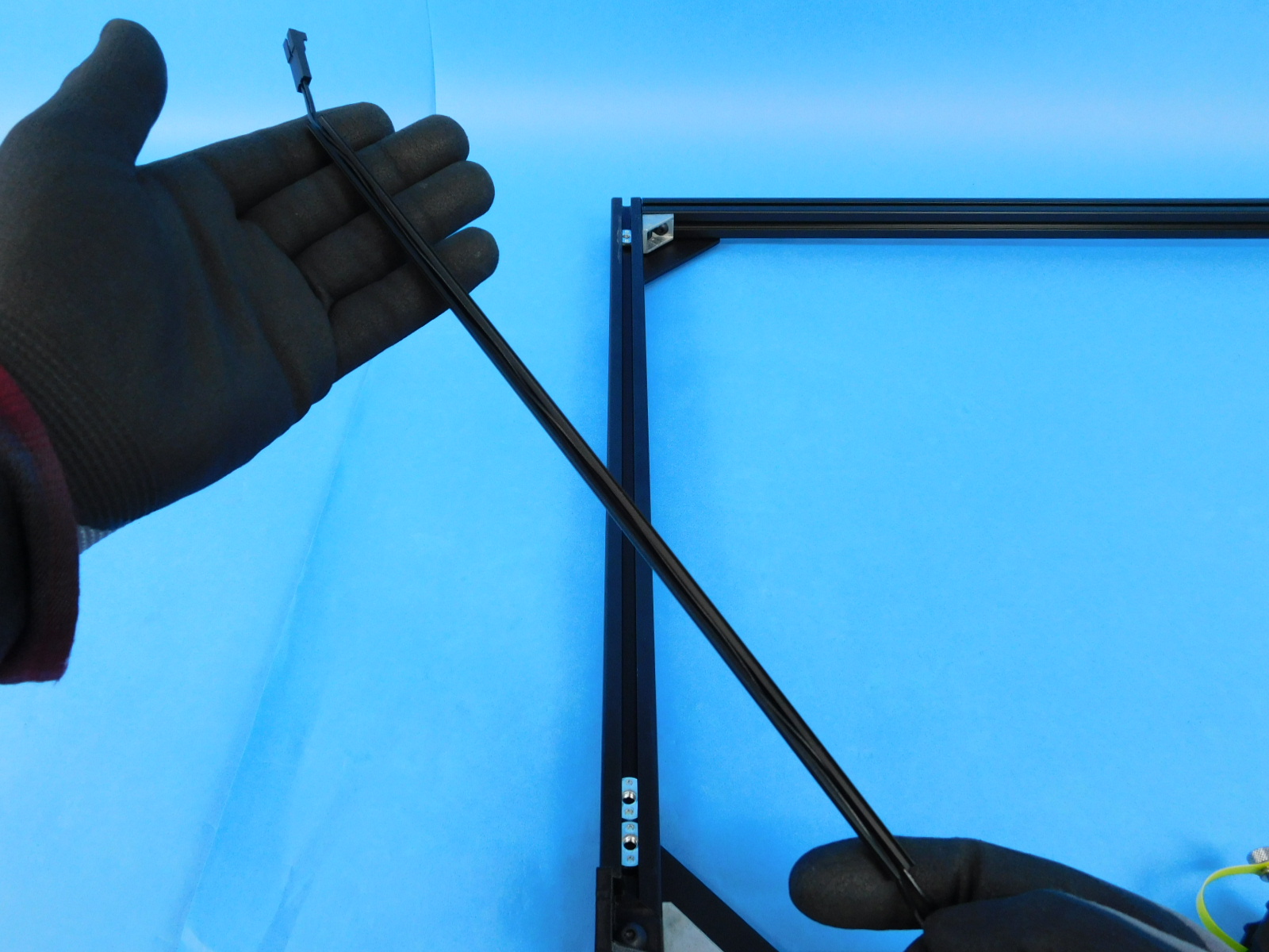
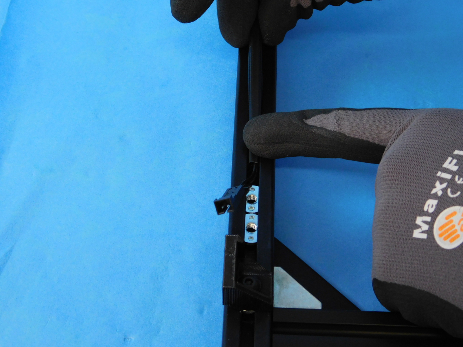
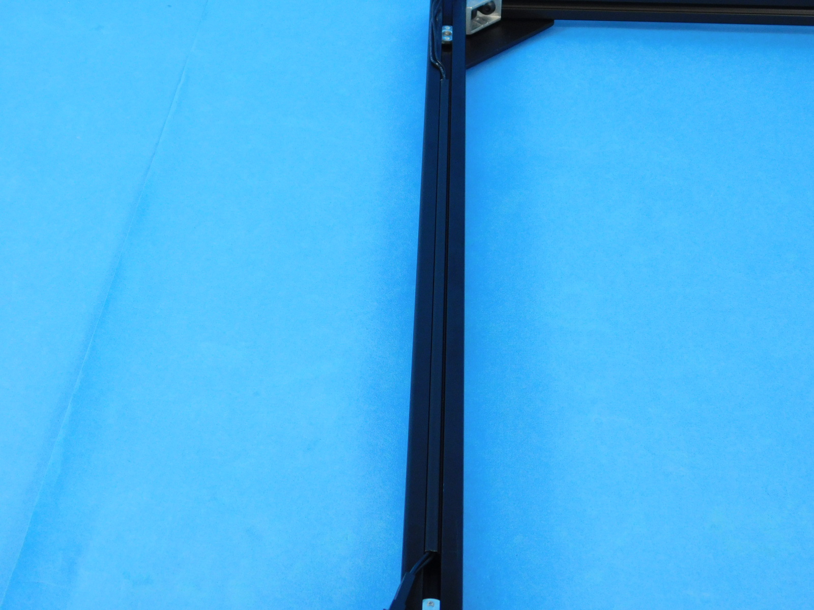
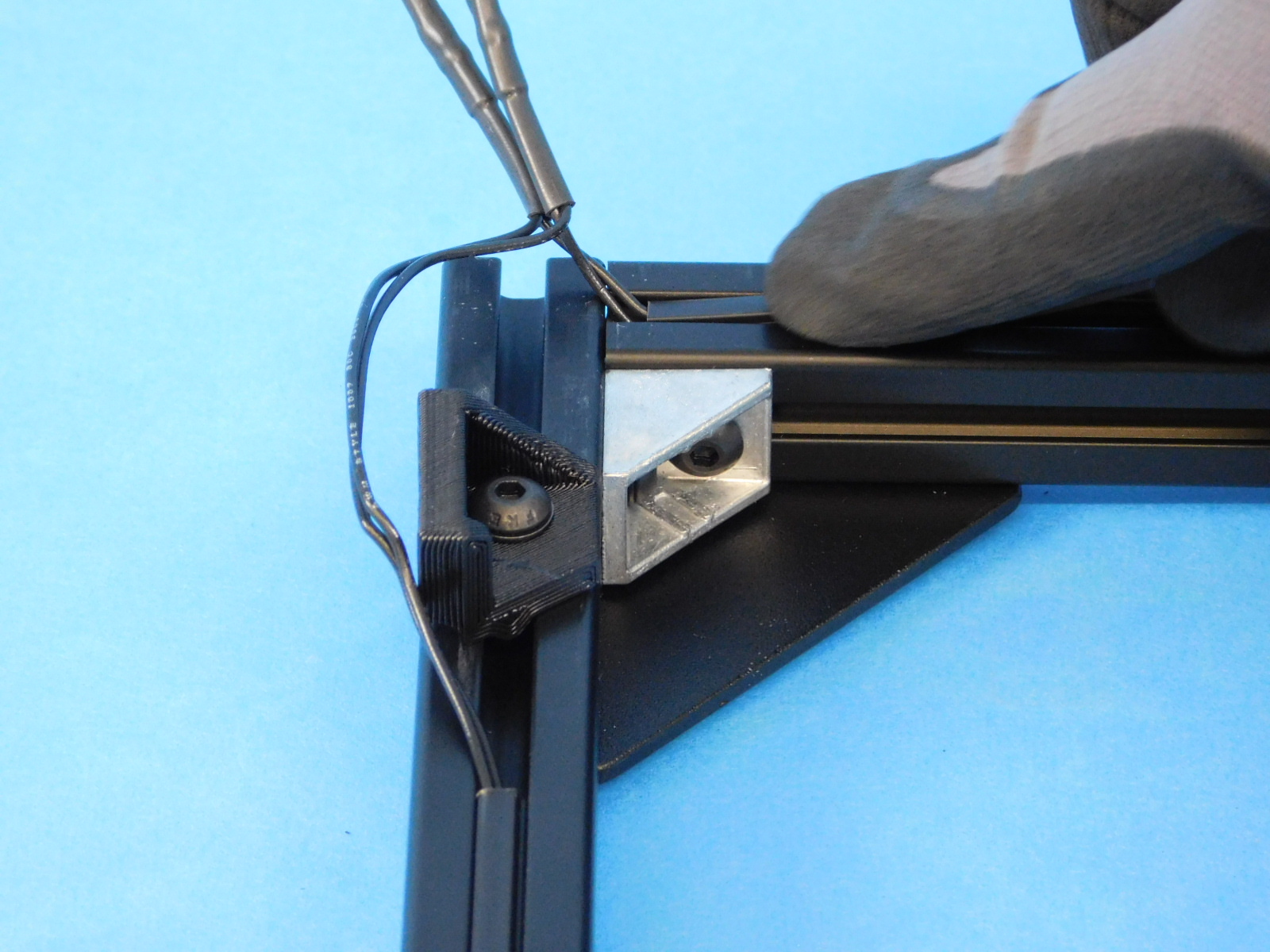
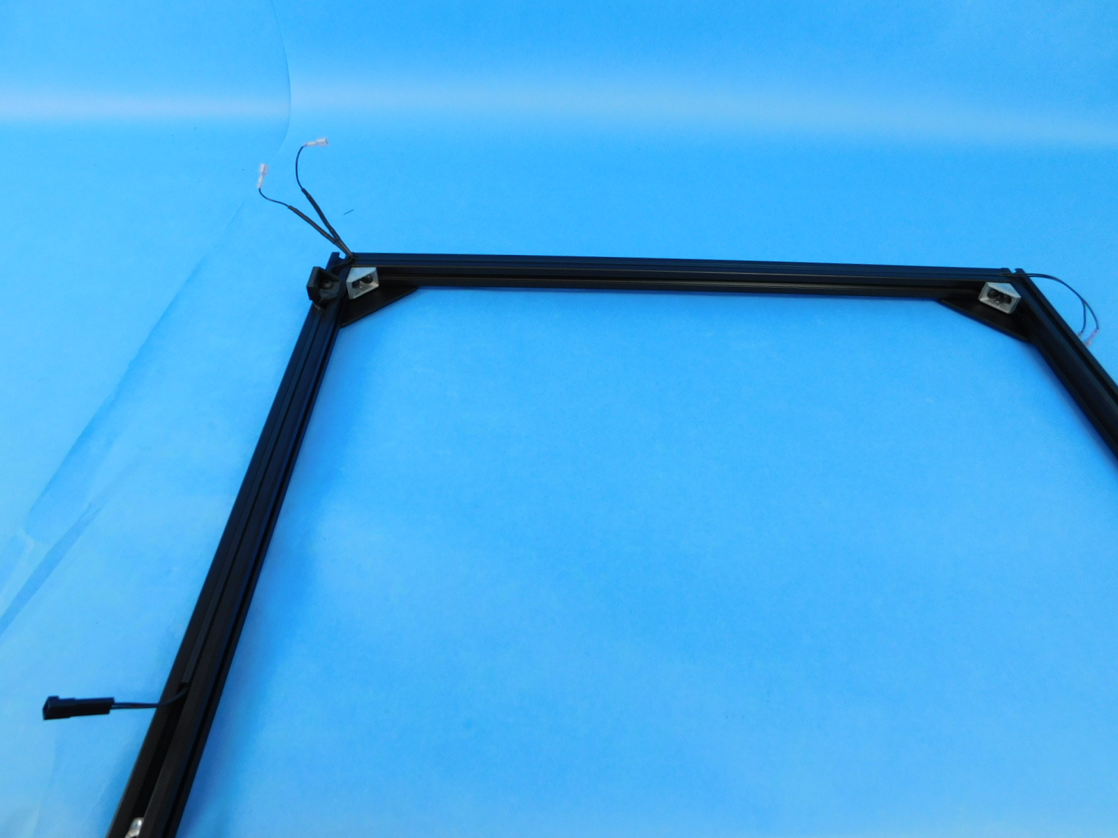
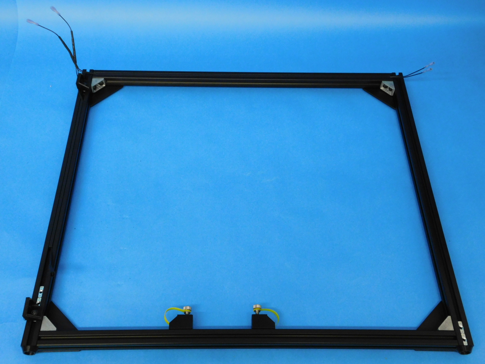
Take the [EL-HR0142] and place it into the frame extrusions as shown. Use the [AS-PR0150] 285mm dust cover and cover the wires on the left side of the frame. Use the [AS-PR0151] 522mm dust cover and cover the wires on the top of the frame.


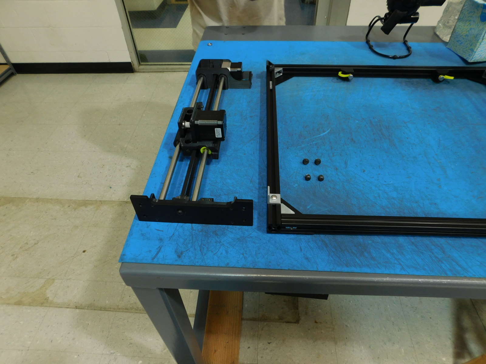
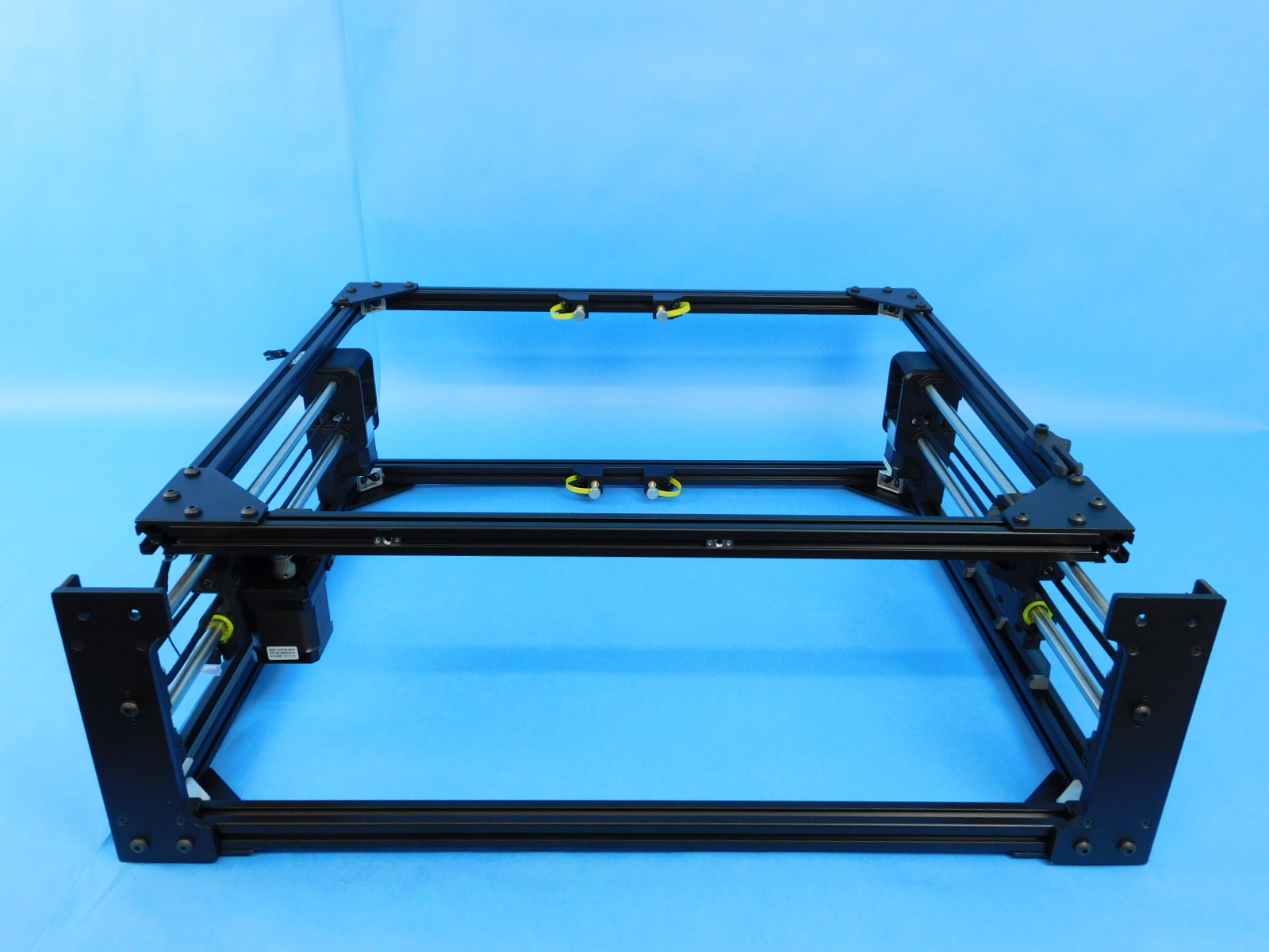
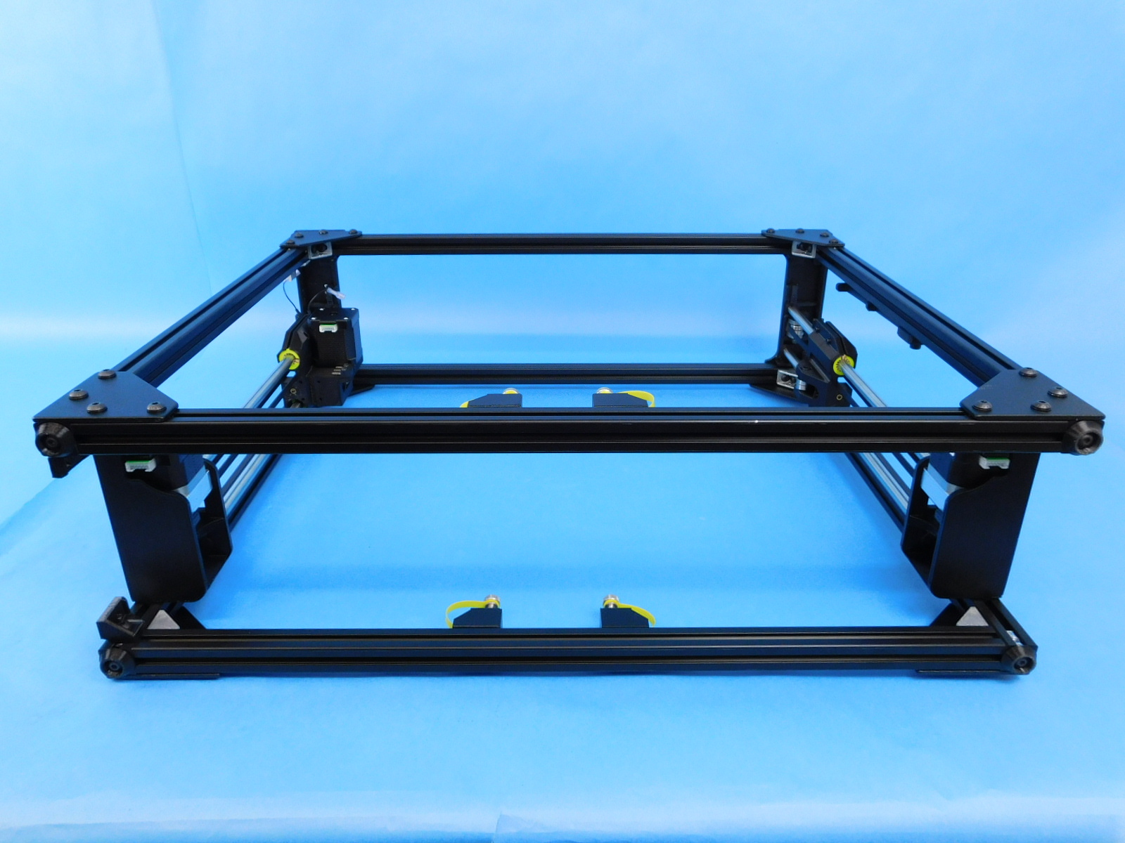
Take the front frame piece and lay it so the bottom of the frame is towards the top.
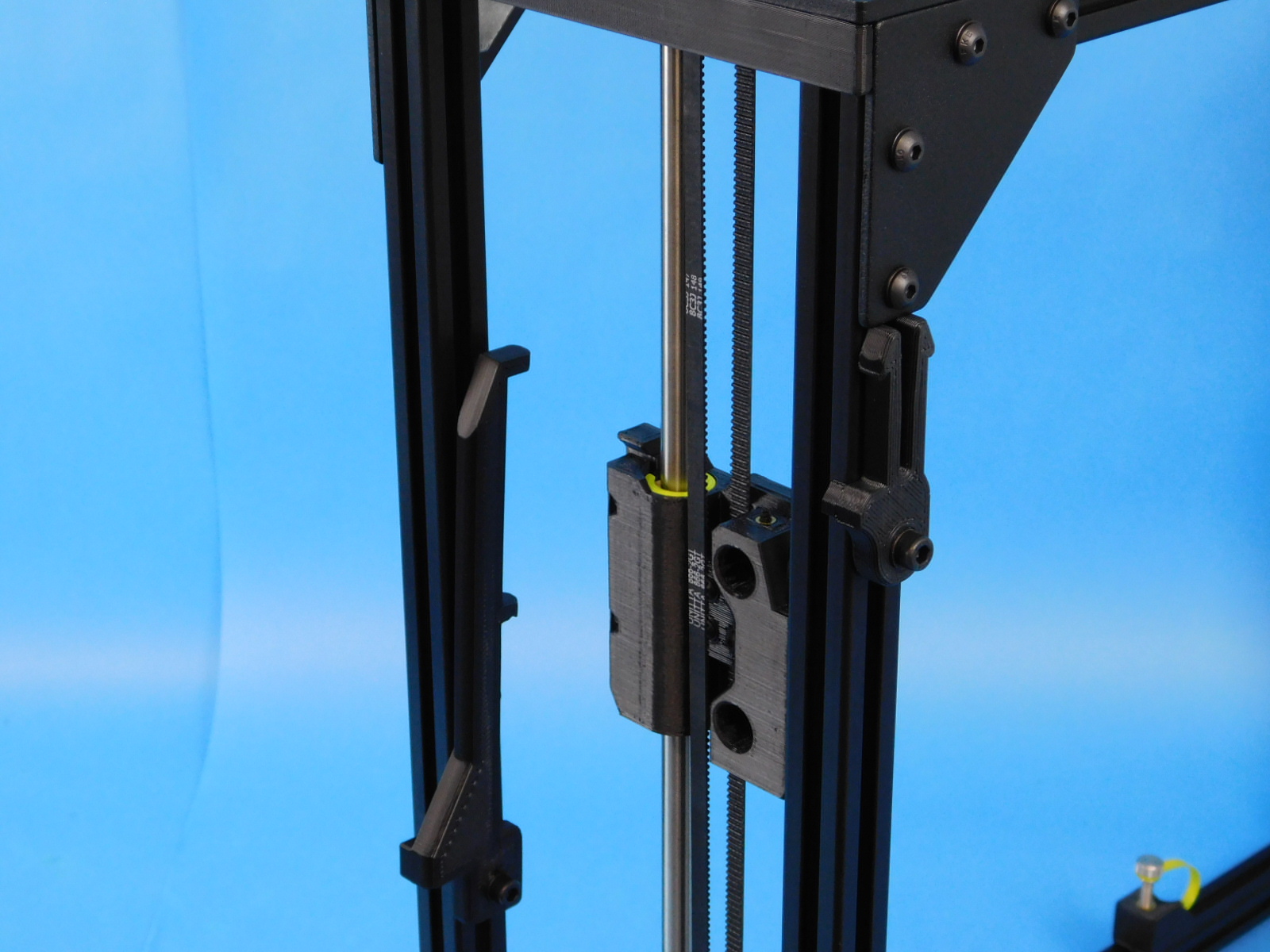
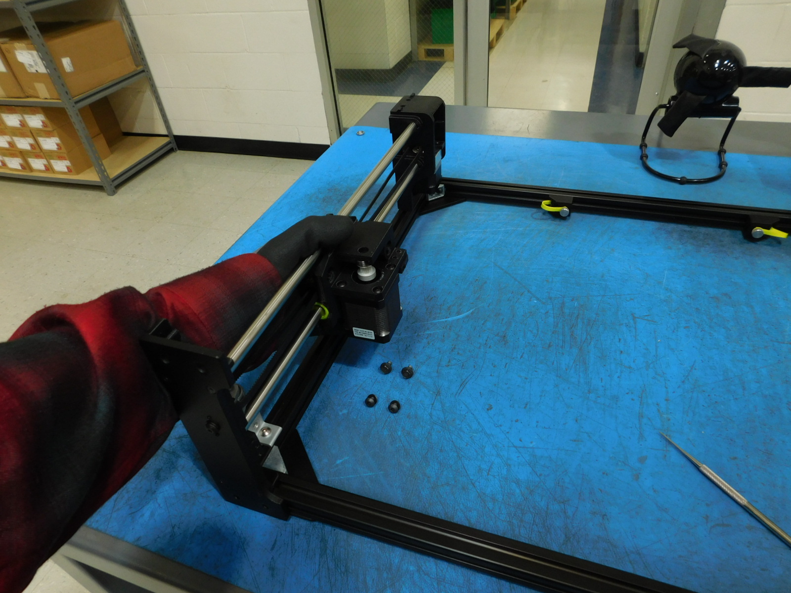
Take the X-End Left [AS-PR0164] and place it on the frame as shown.
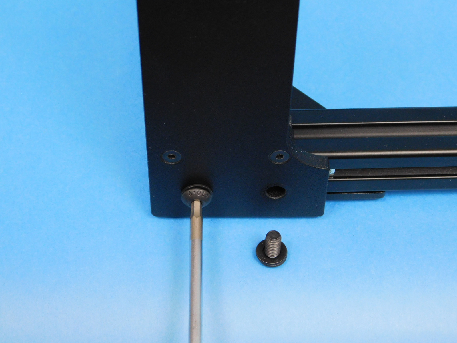
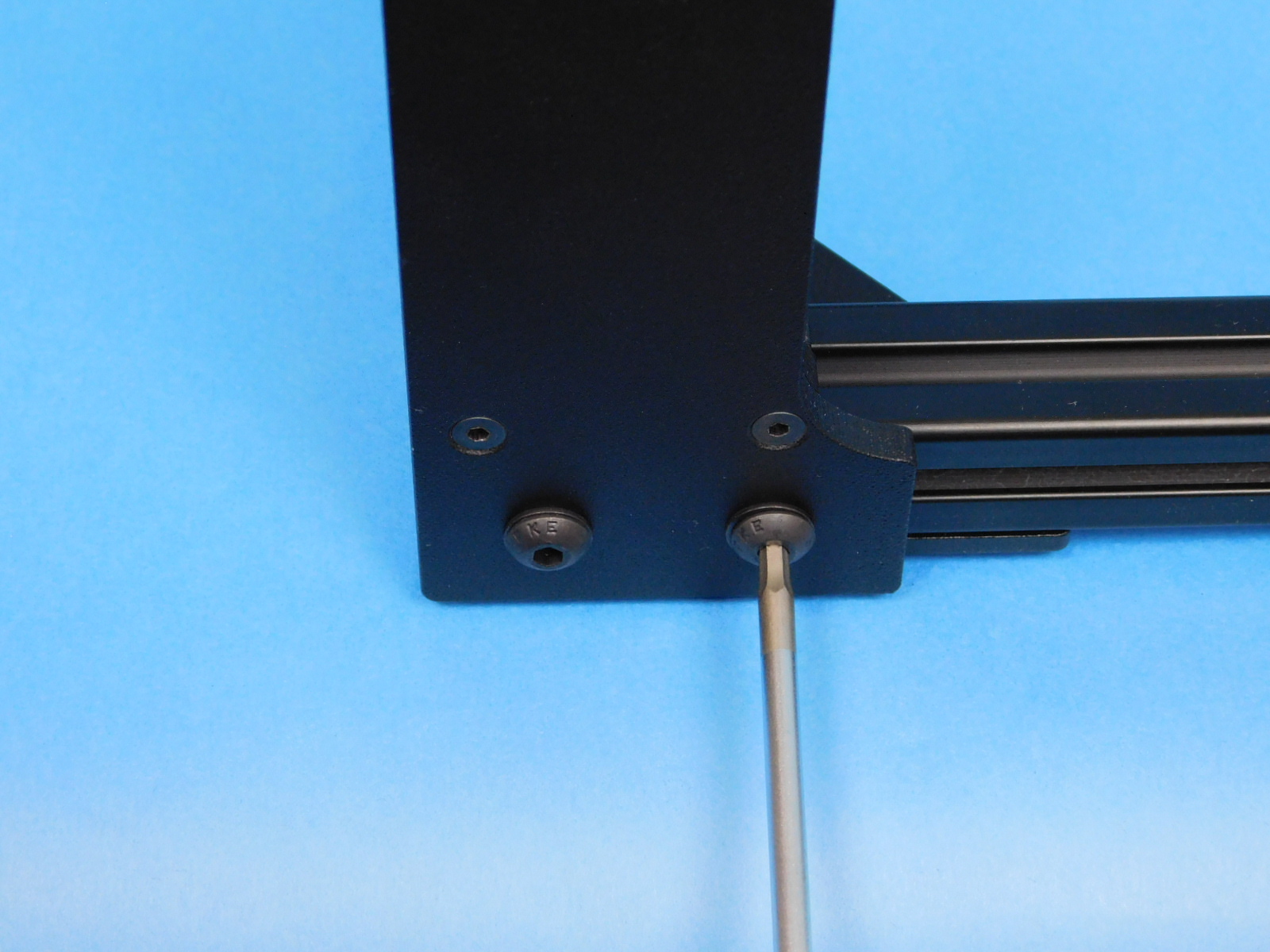
Use two [HD-BT0073] M5 x 10 BHCS and two [HD-WA0040] M5 washer, screw the z-upper tho the frame as shown.
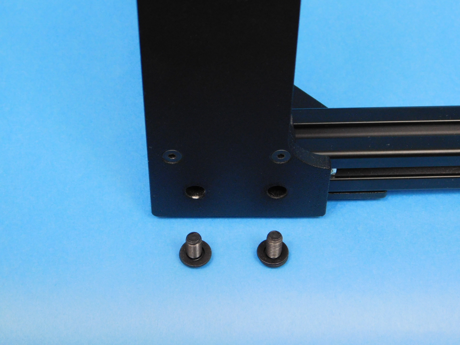
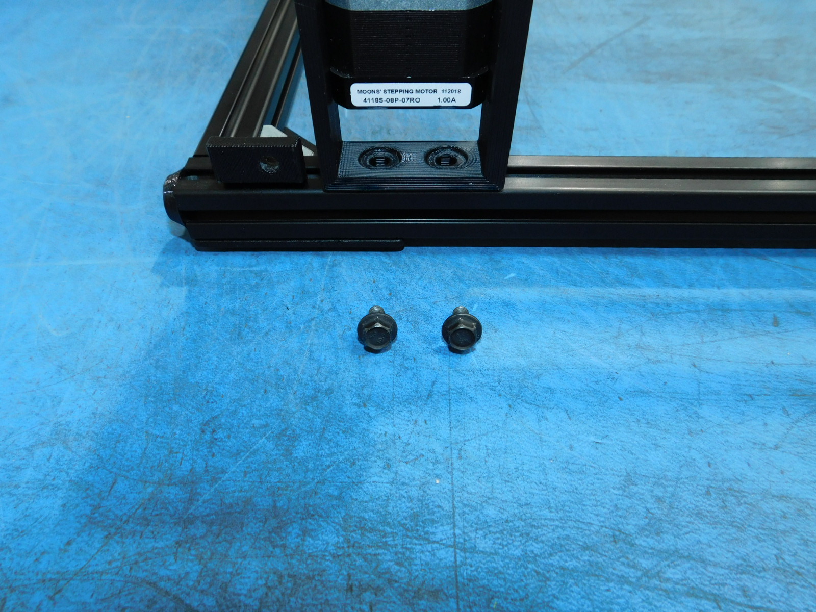
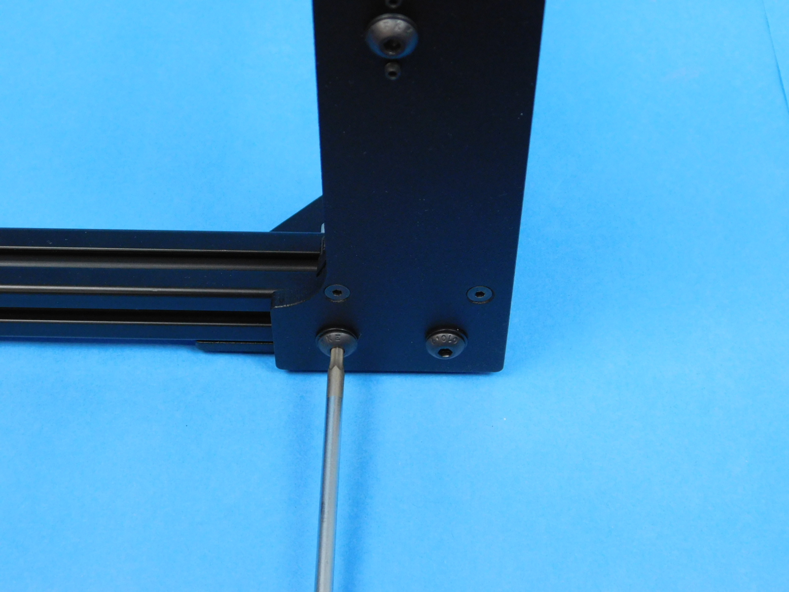
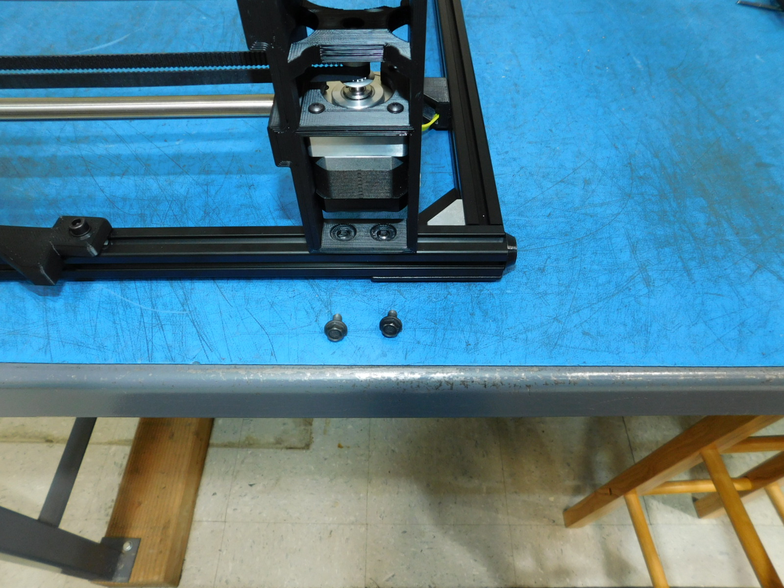
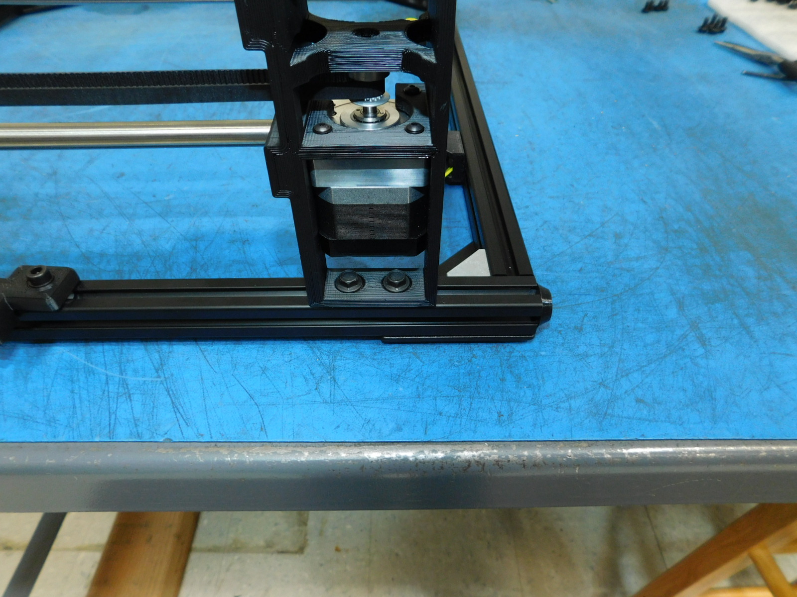
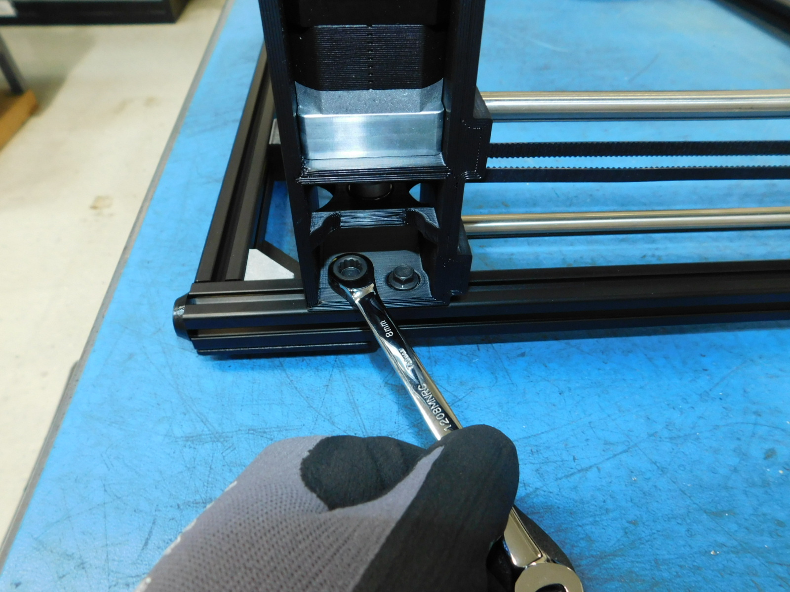
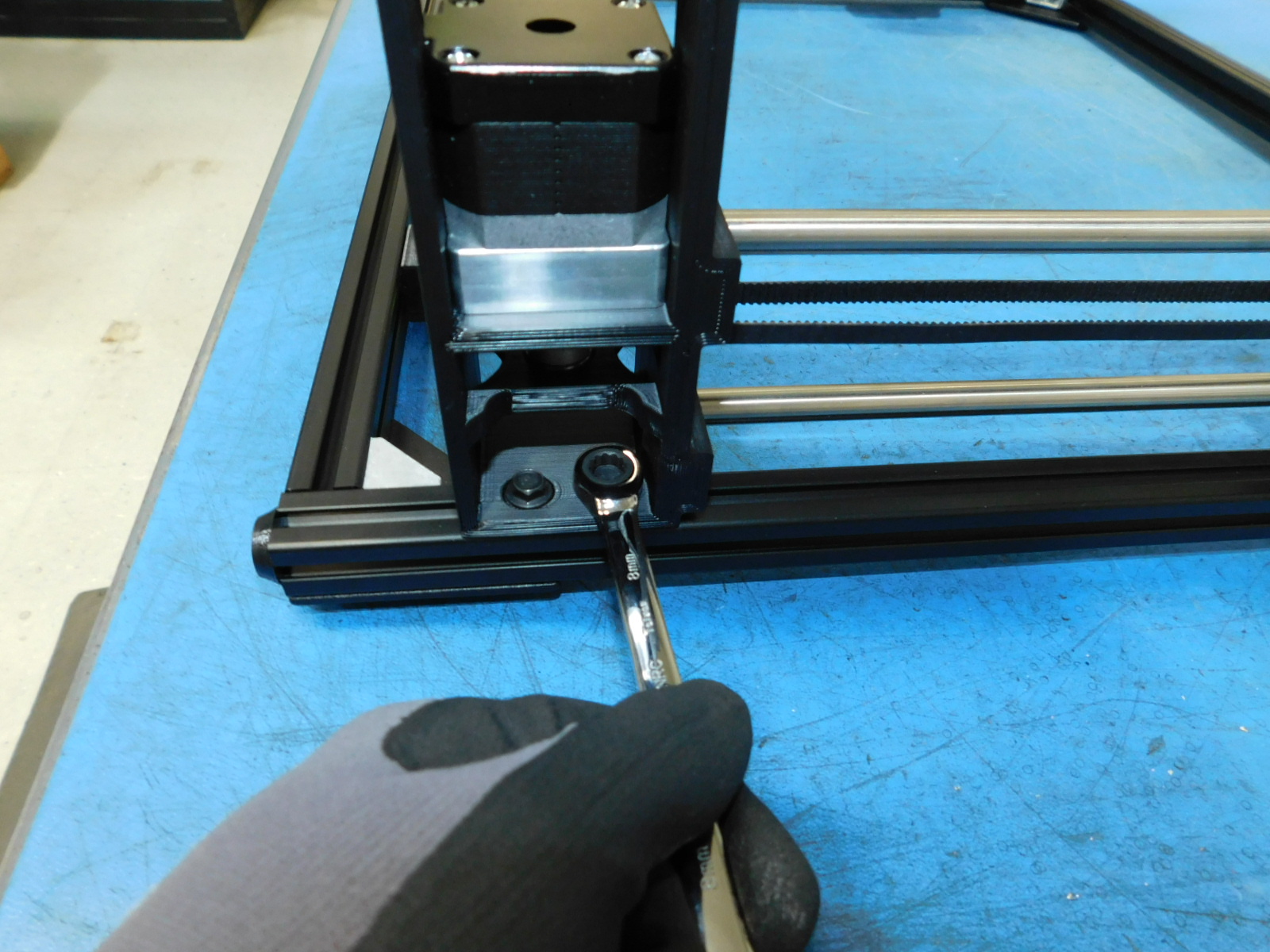
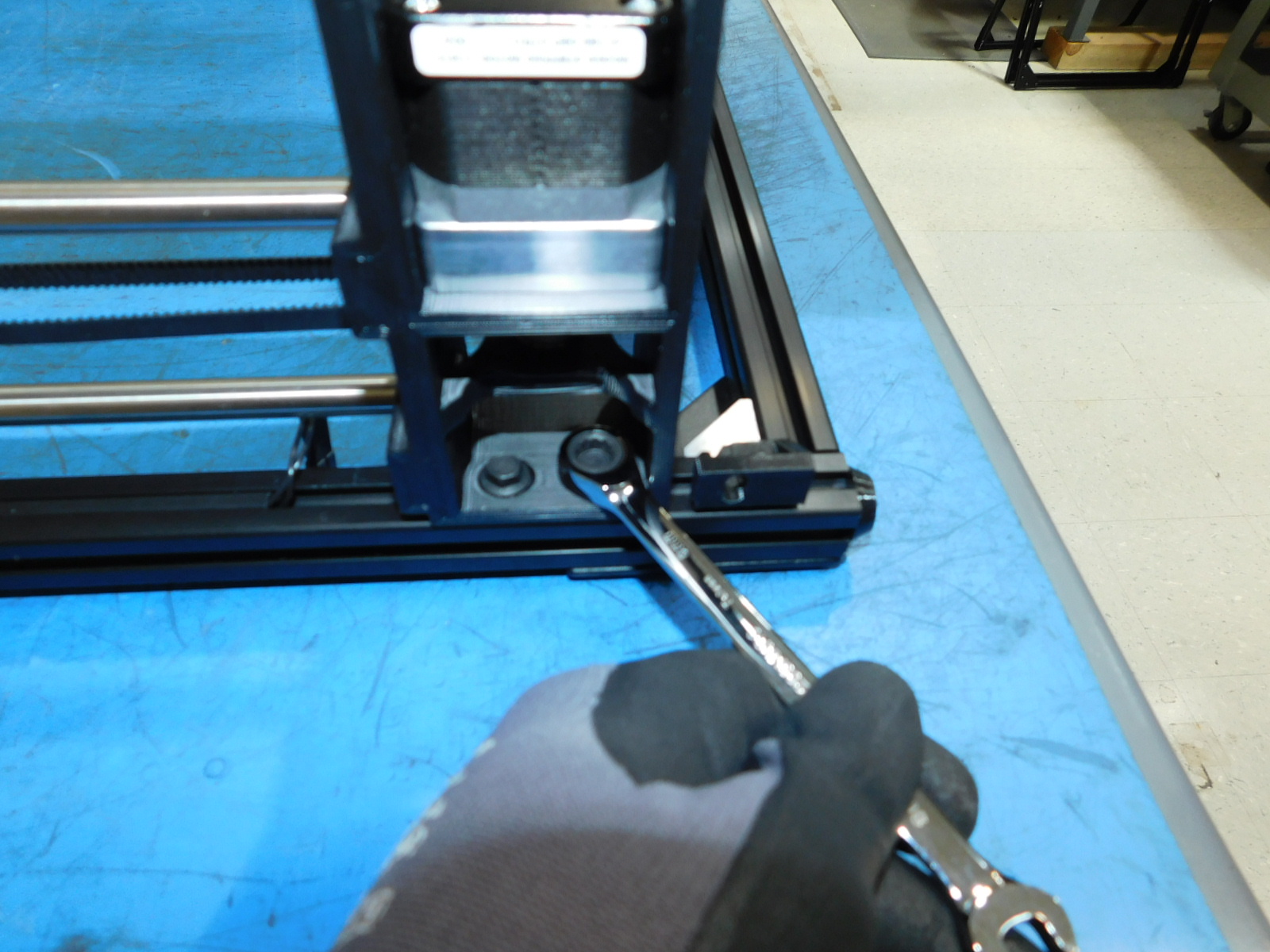
Use two M5x10 Flanged Hex Head [HD-BT0250] to attach the z-lower to the frame.
Take the X-End Idler Assembly [AS-PR0130] and place it on the frame as shown.
Use two [HD-BT0073] M5 x 10 BHCS and two [HD-WA0040] M5 washer and attach the z-upper to the frame.
Use two [HD-BT0250] M5 x 10 Flanged Hex Head to attach the z-lower to the frame.
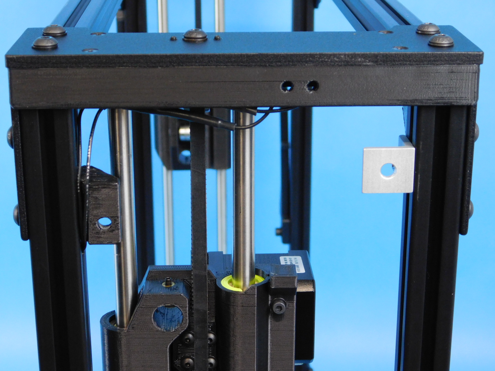
Take the assembled back frame and place it onto the x-ends as shown. Do not pinch the wires for the z-max switches when sliding the back frame onto the x-ends.
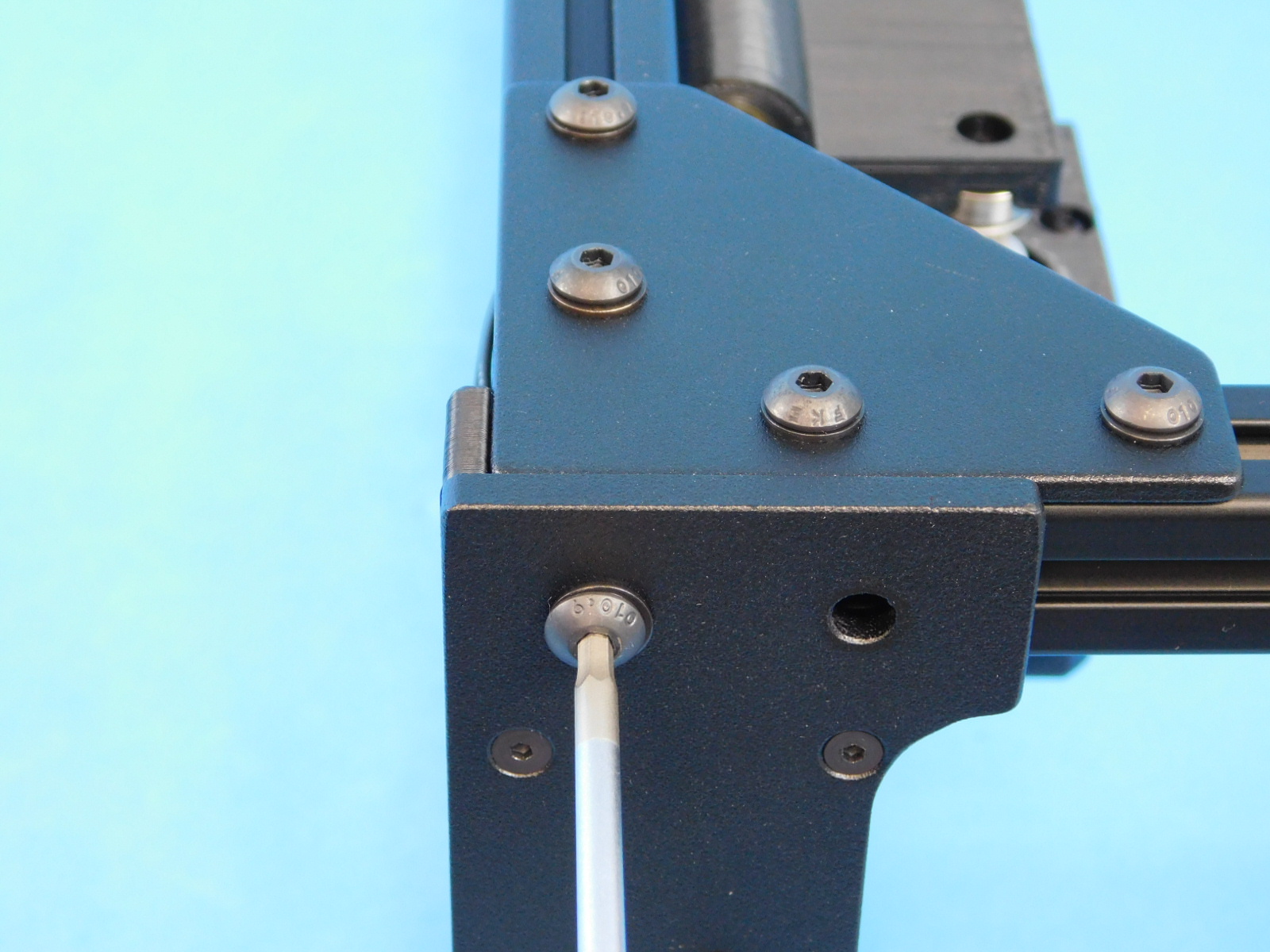
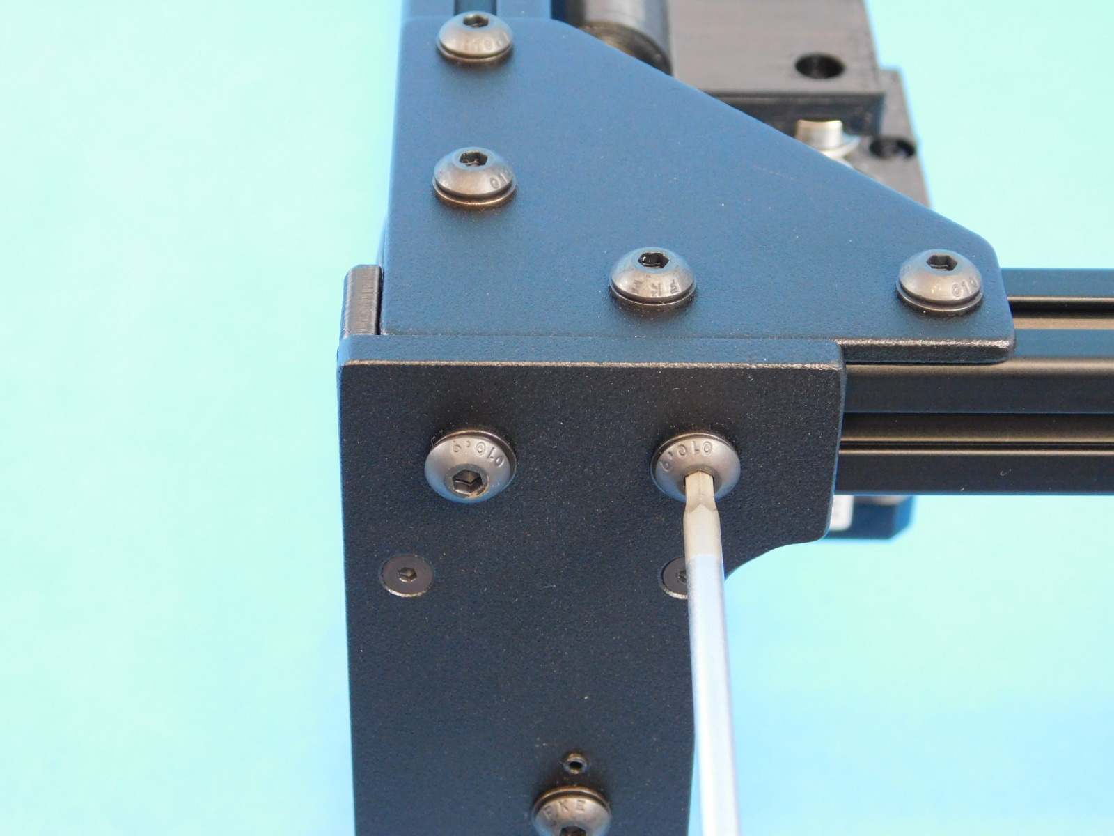
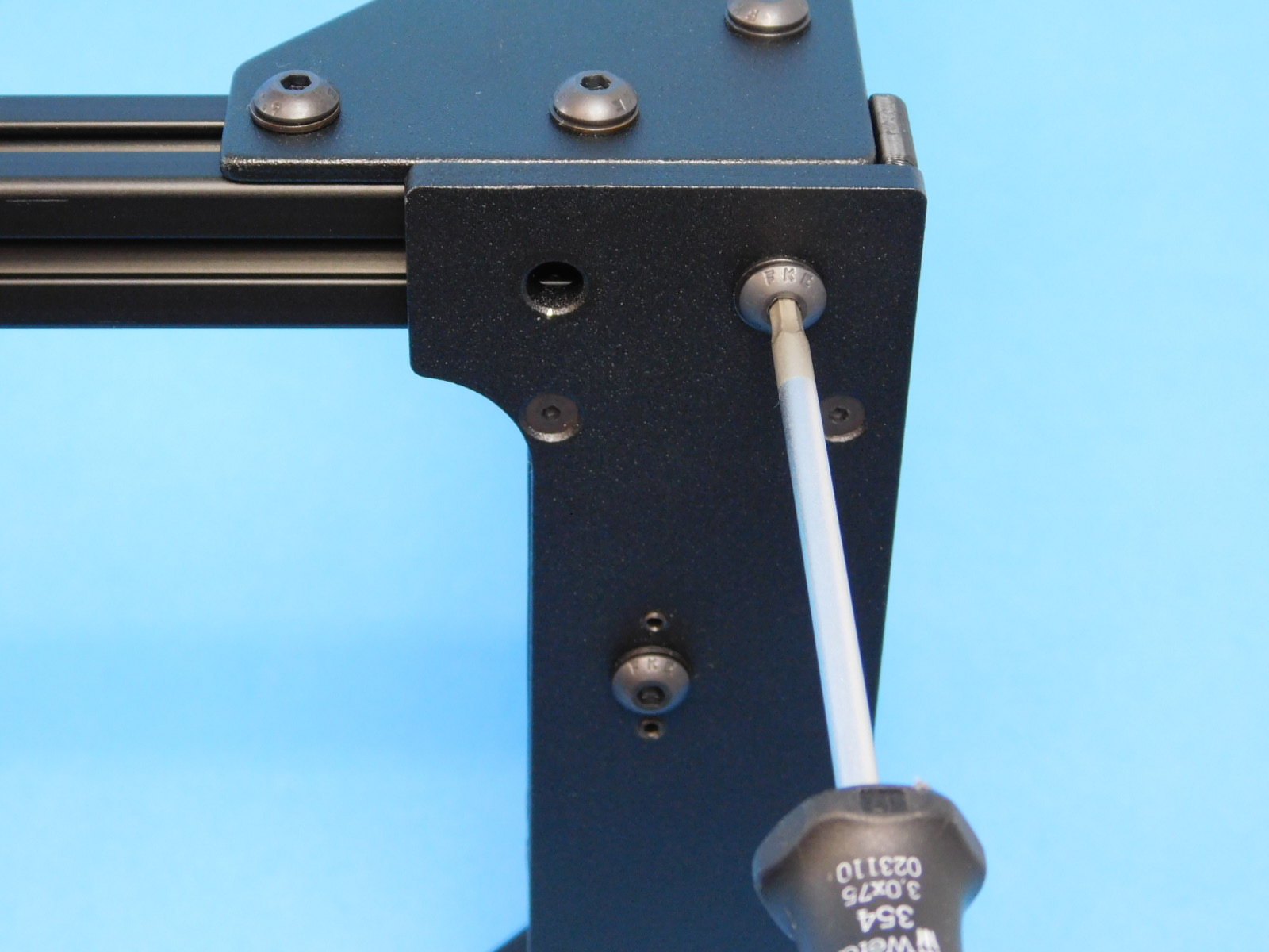
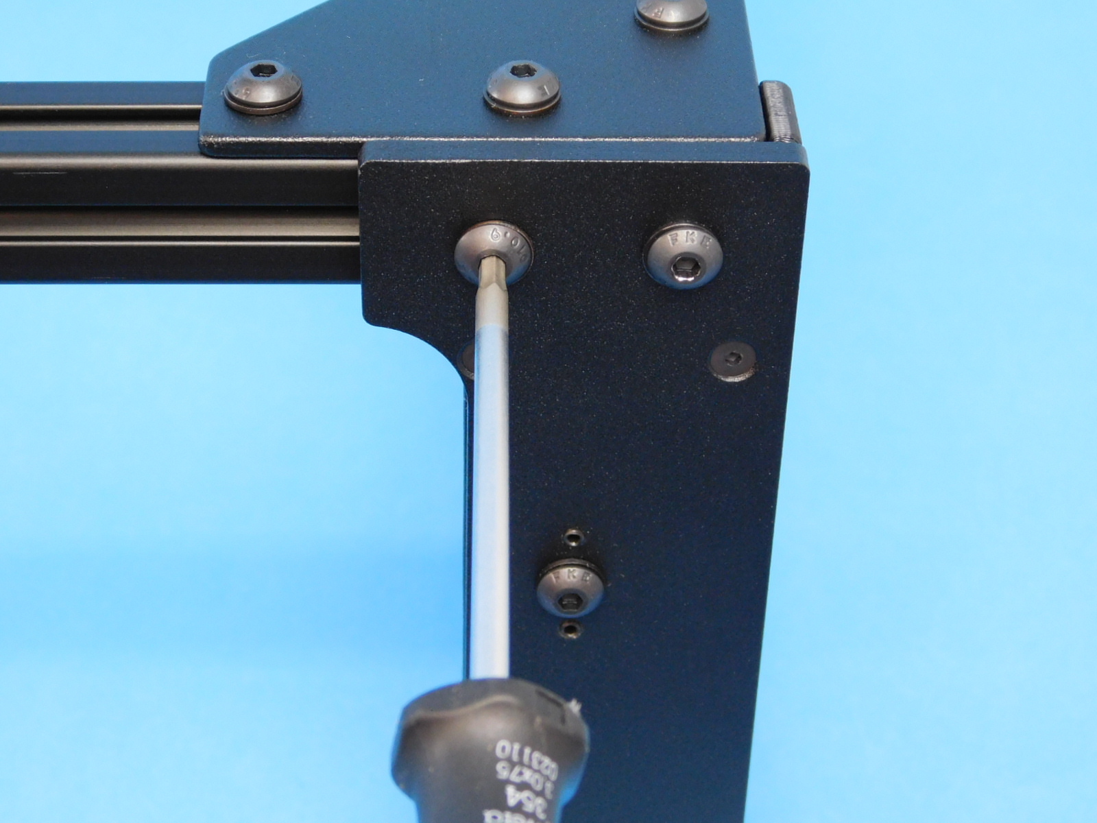
Use four [HD-BT0073] M5 x 10 BHCS and four [HD-WA0040] M5 washers, and attach the z-uppers to the frame.
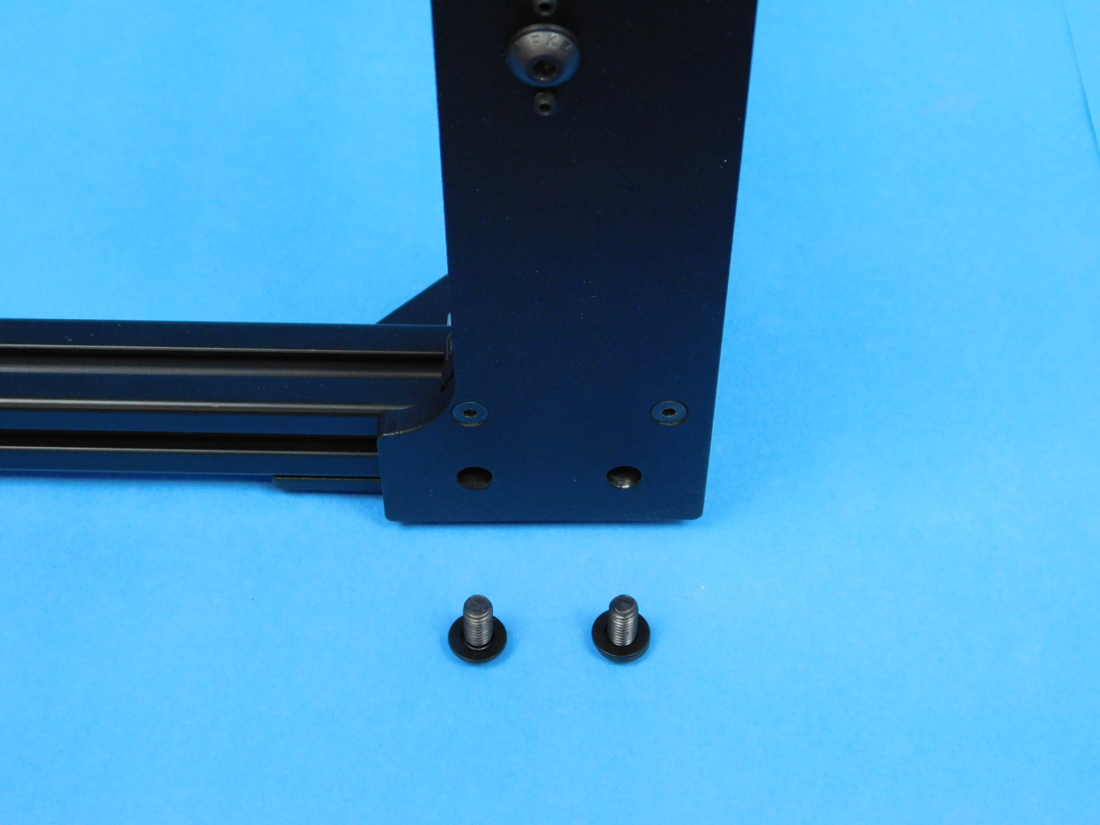
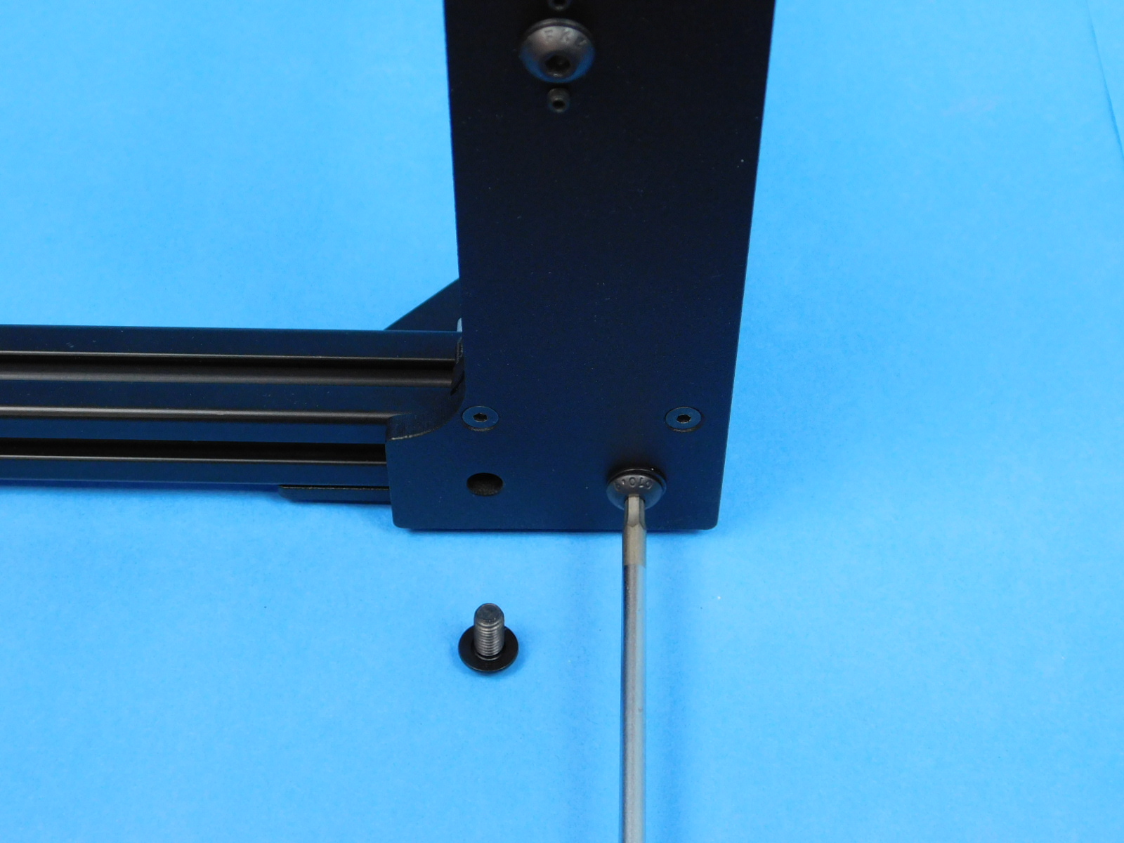
Flip the frame over so the screw holes for the z-lowers are facing you.
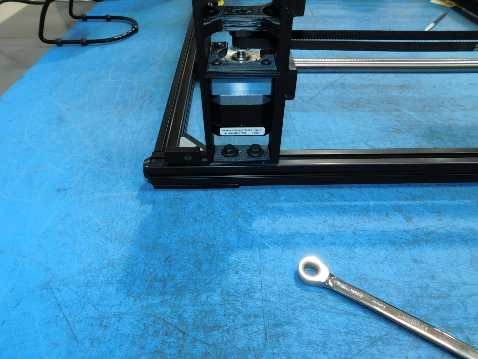
Use four [HD-BT0250] M5 x 10 Flanged Hex Head to secure the z-lowers to the frame.
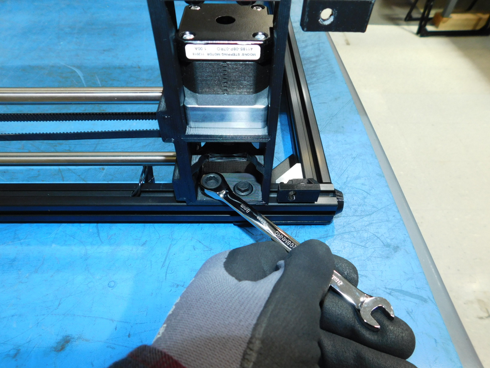
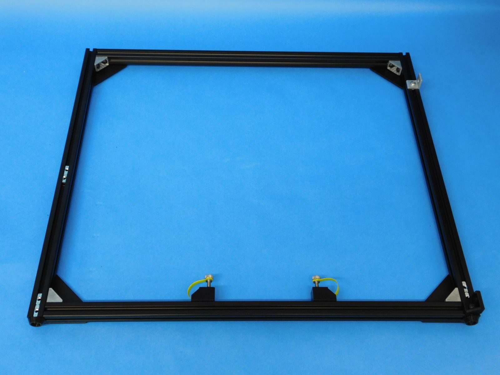
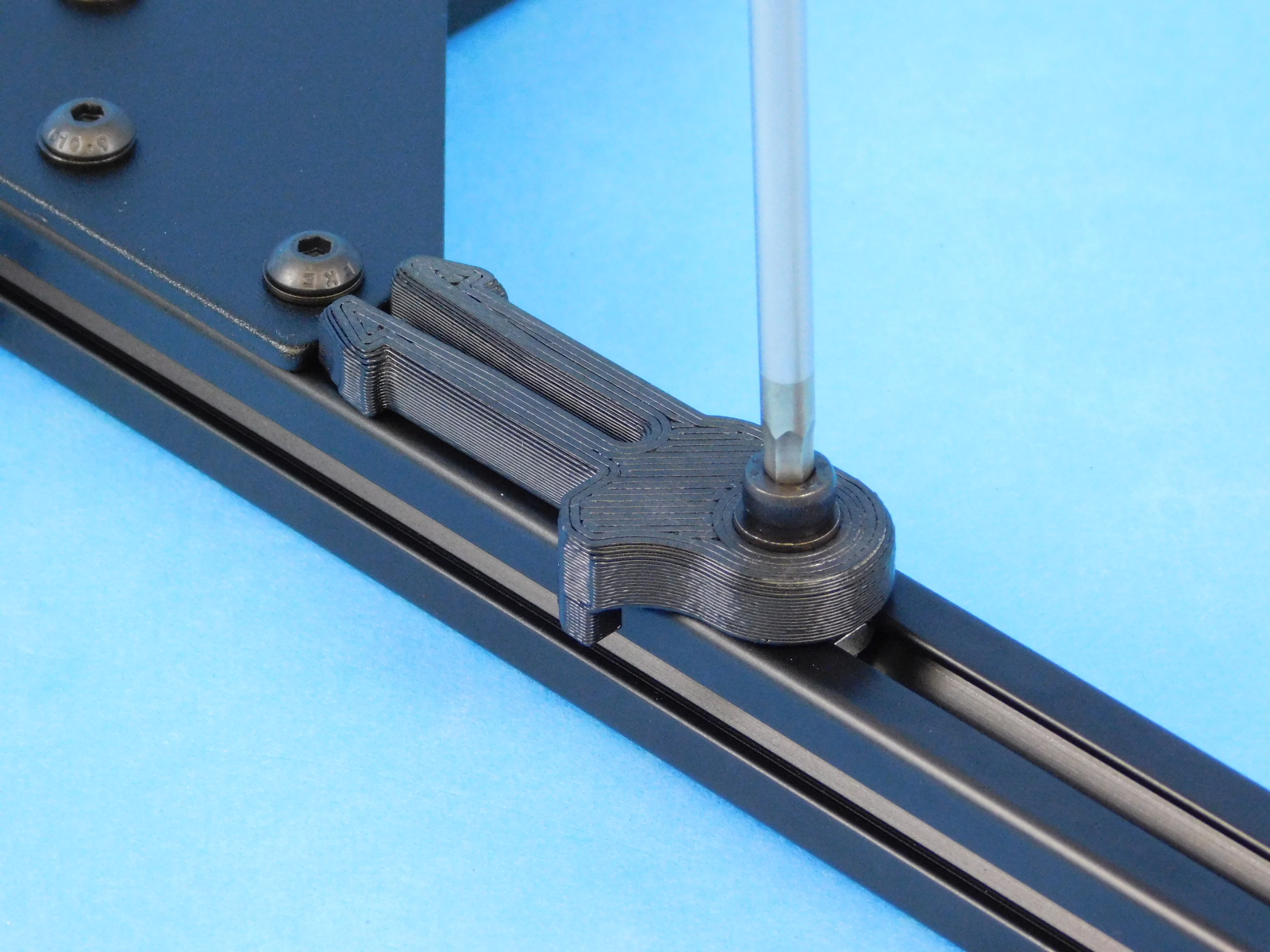
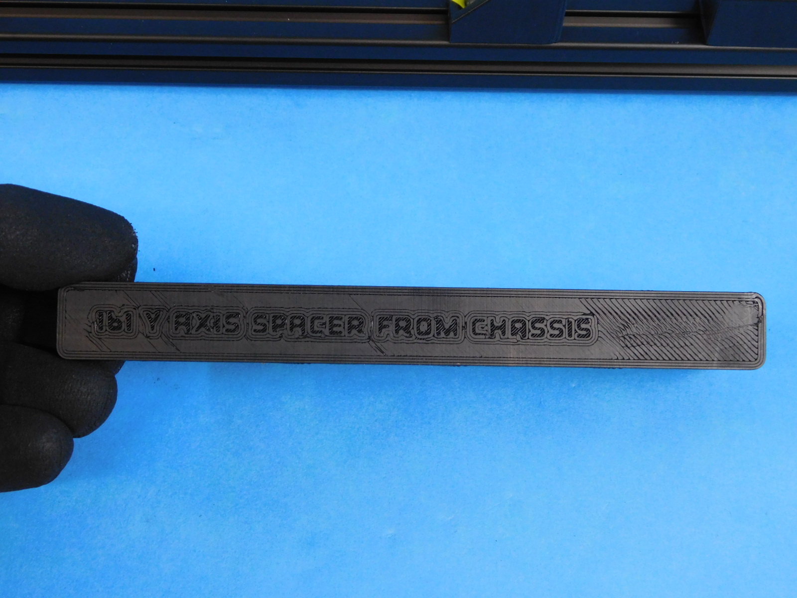
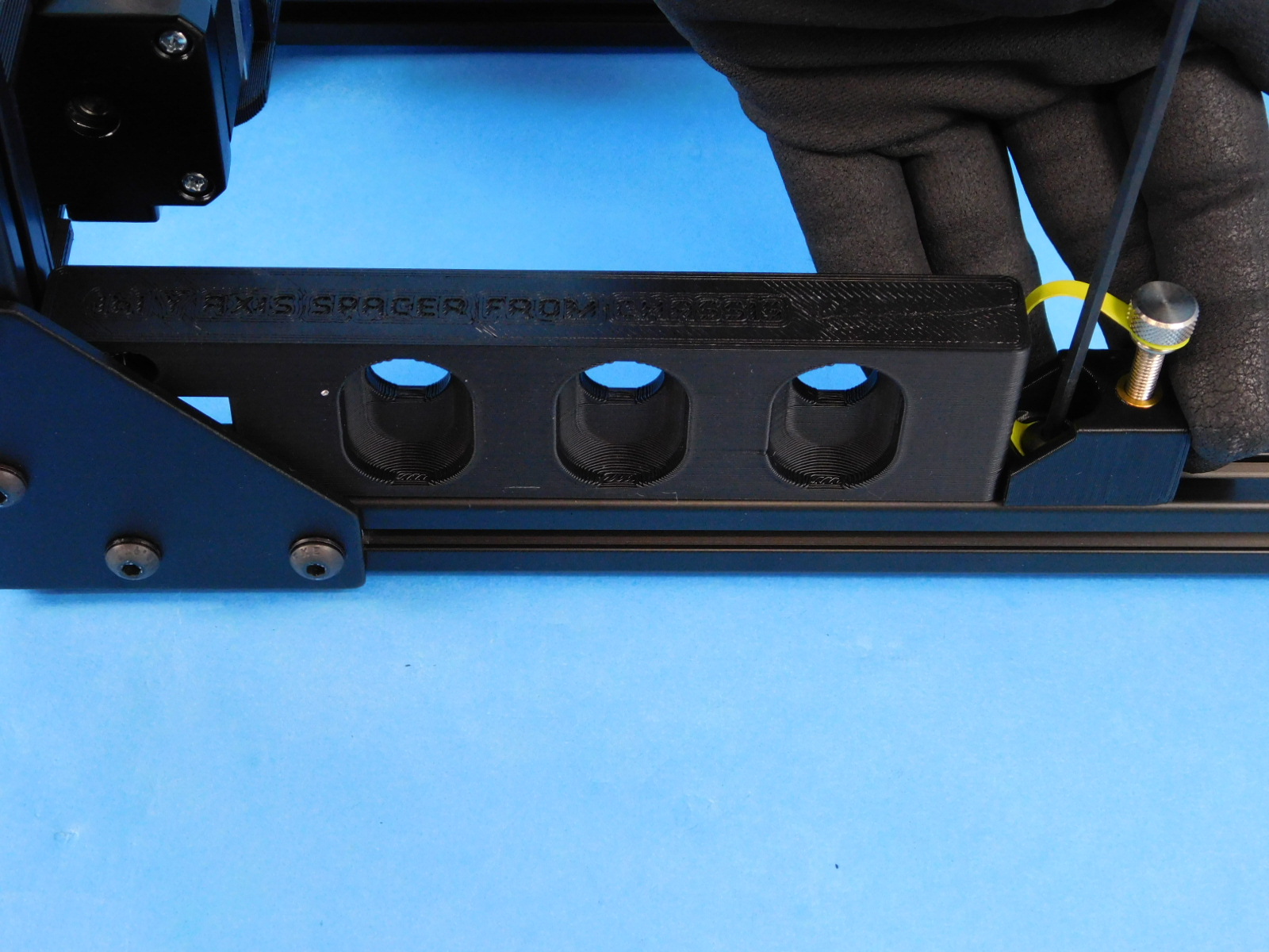
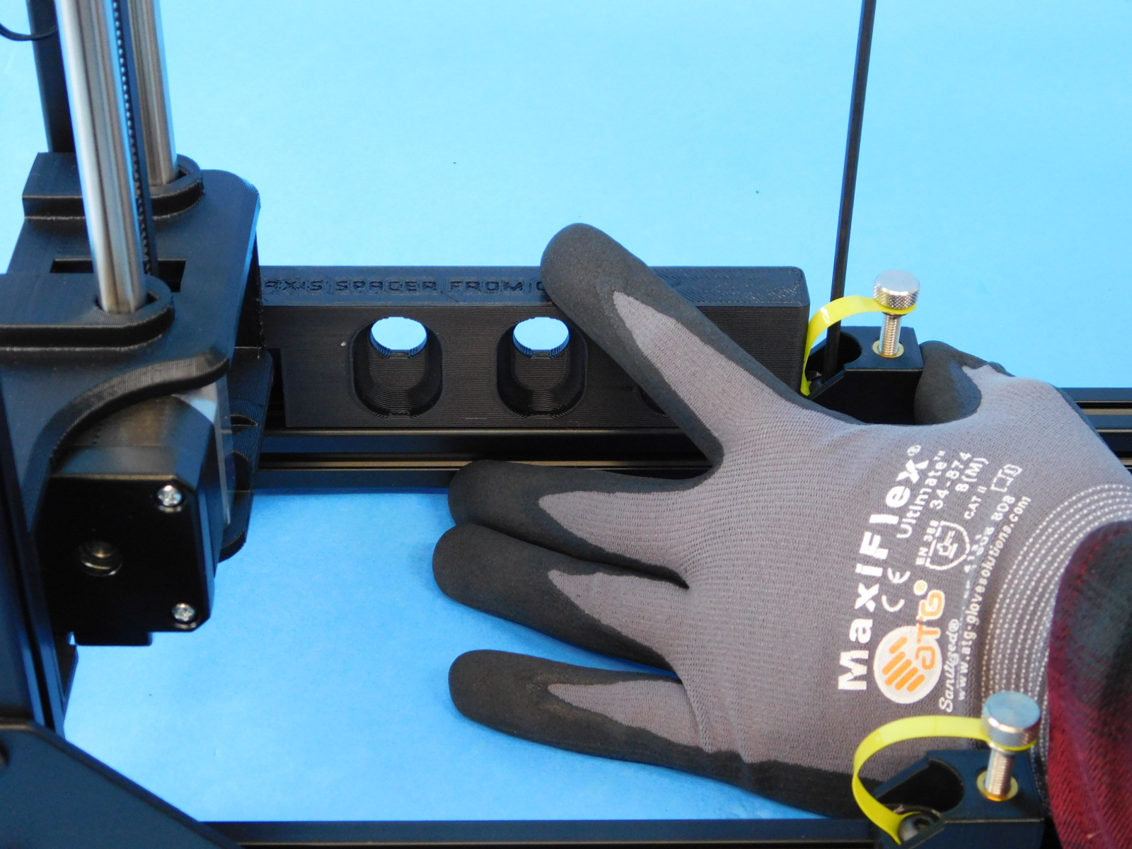
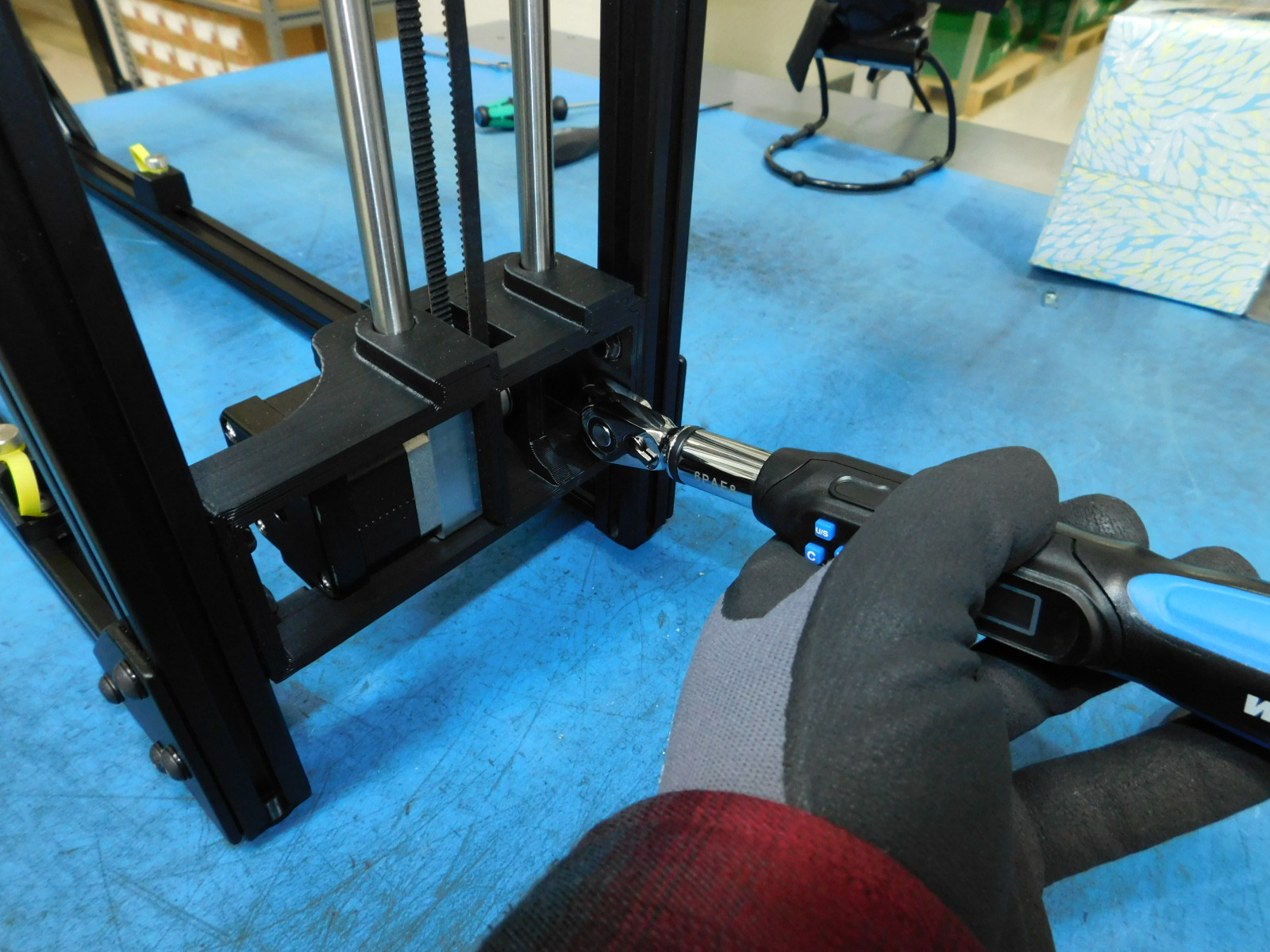
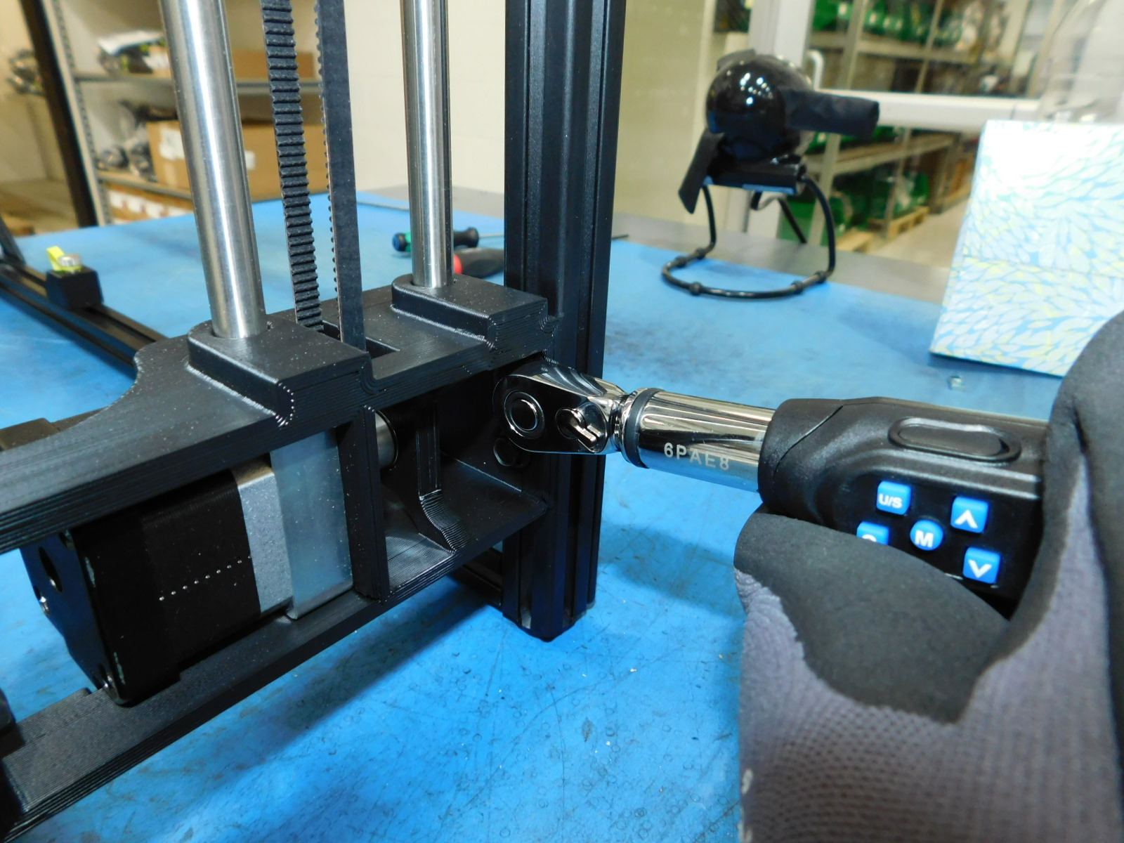
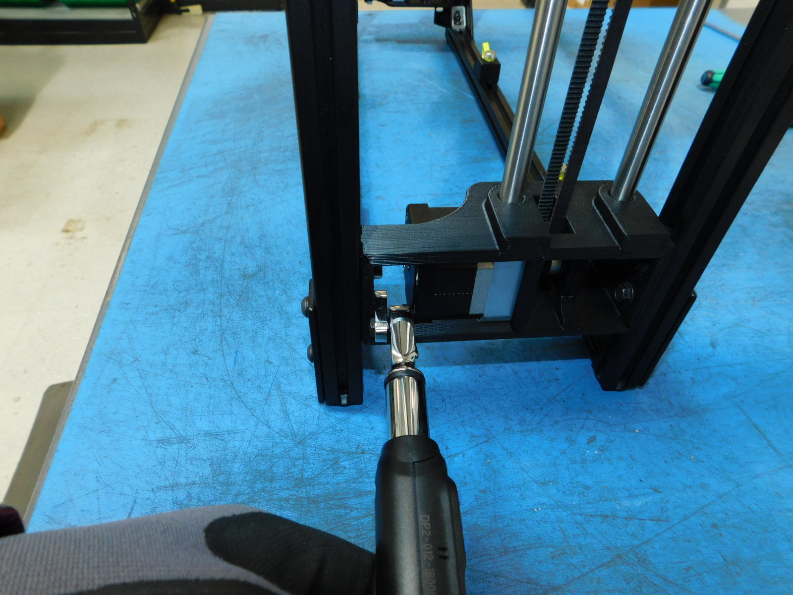
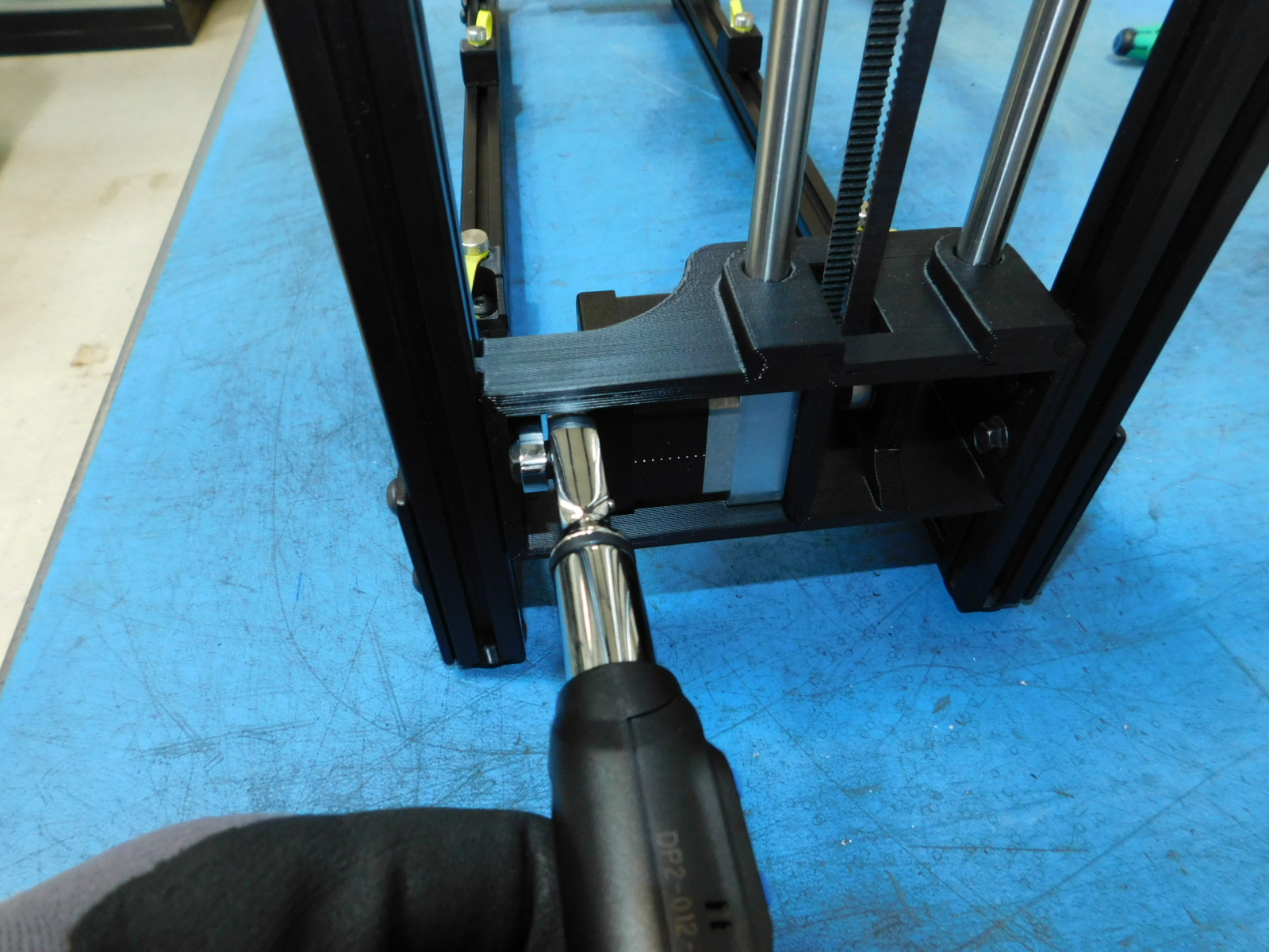
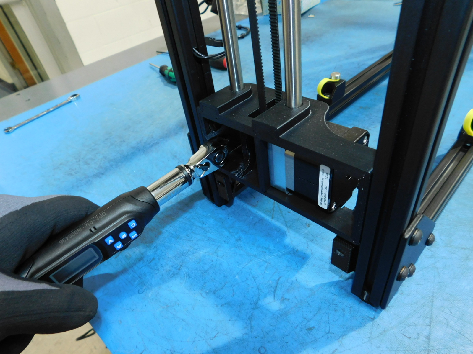
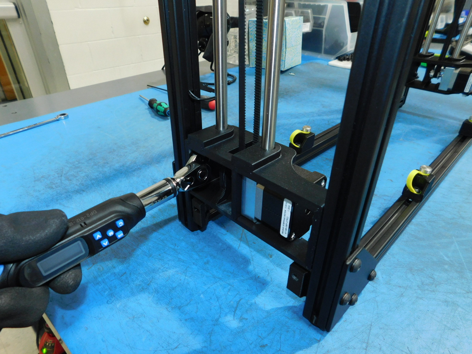
Use the spacing jig for the left two Y-Mount Chassis [PP-IS0098] to get the proper placement.
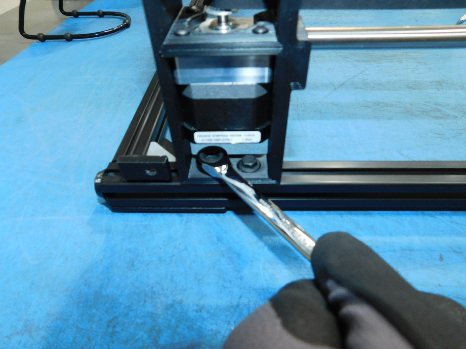
Slide the chassis mount against the jig and torque the fastener 5in*lbs
The 4 frame feet must be removed for this step
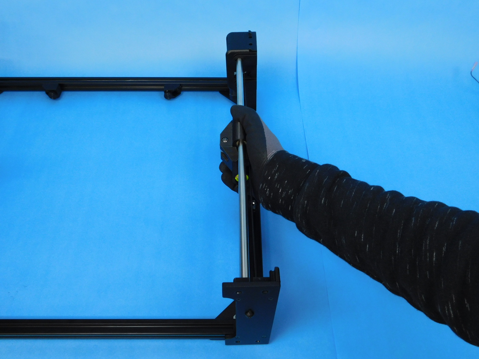
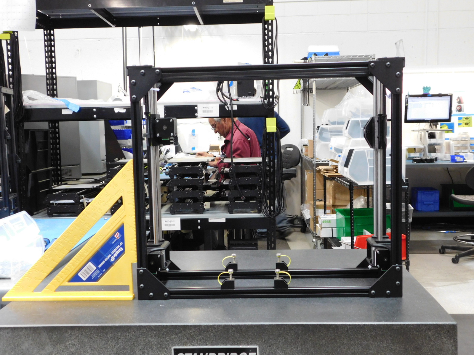
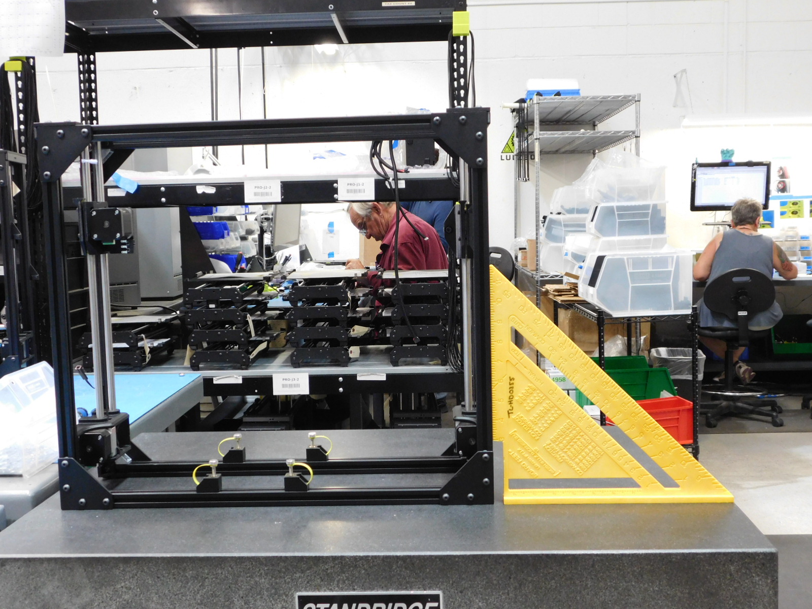
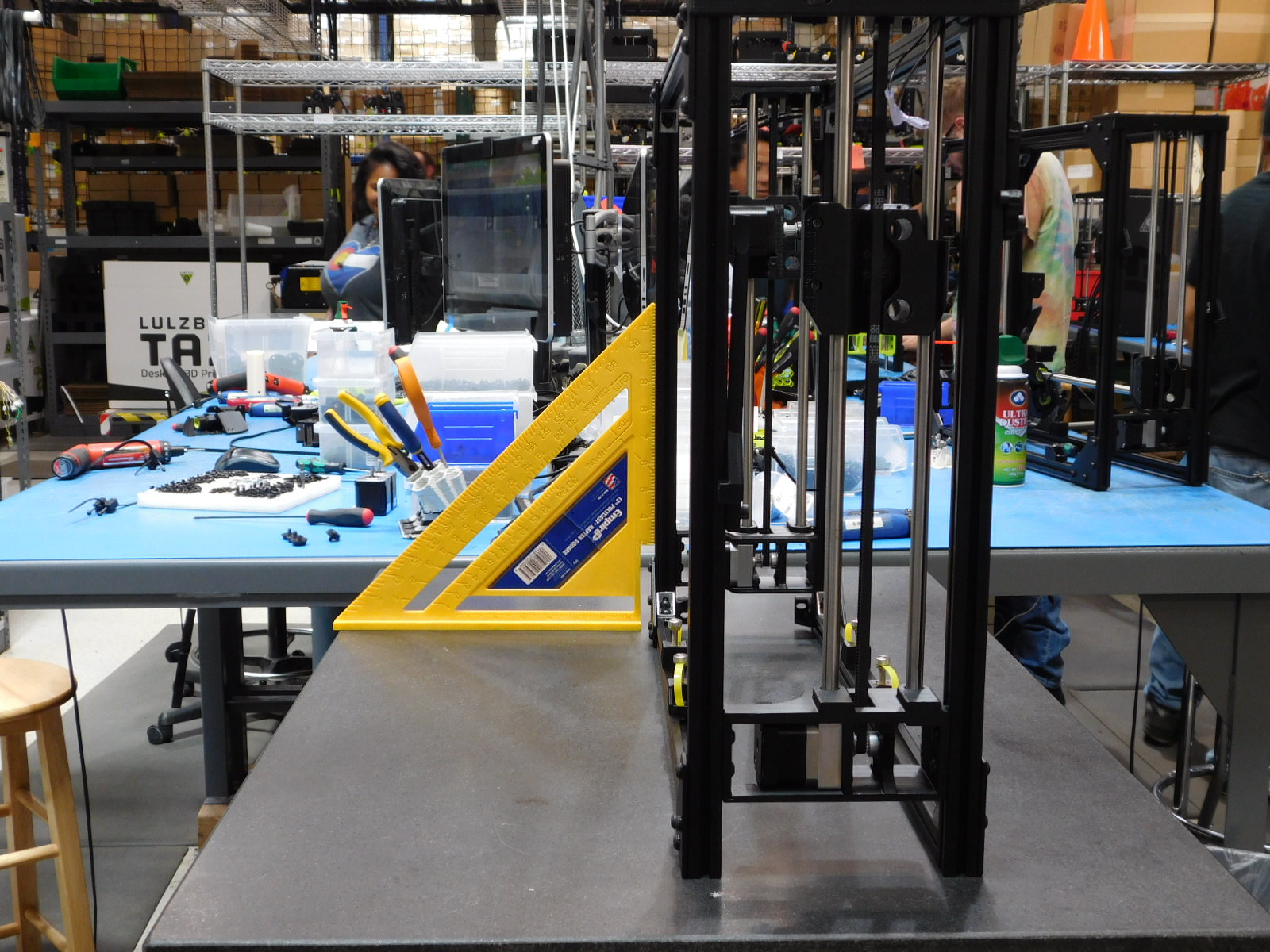
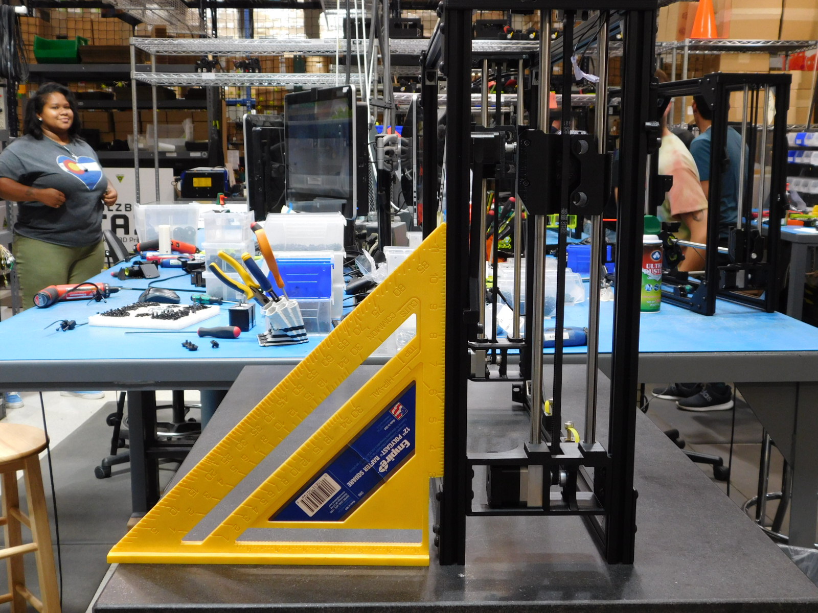
Take the frame to the granite block and check the squareness of the frame. Use a 12" rafter square to check the frame for squareness. The frame must be within 2mm of the rafter scale on either the top or bottom of the square.
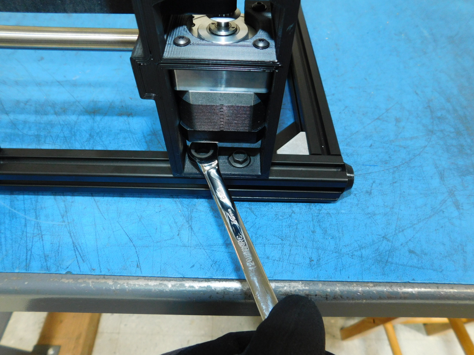
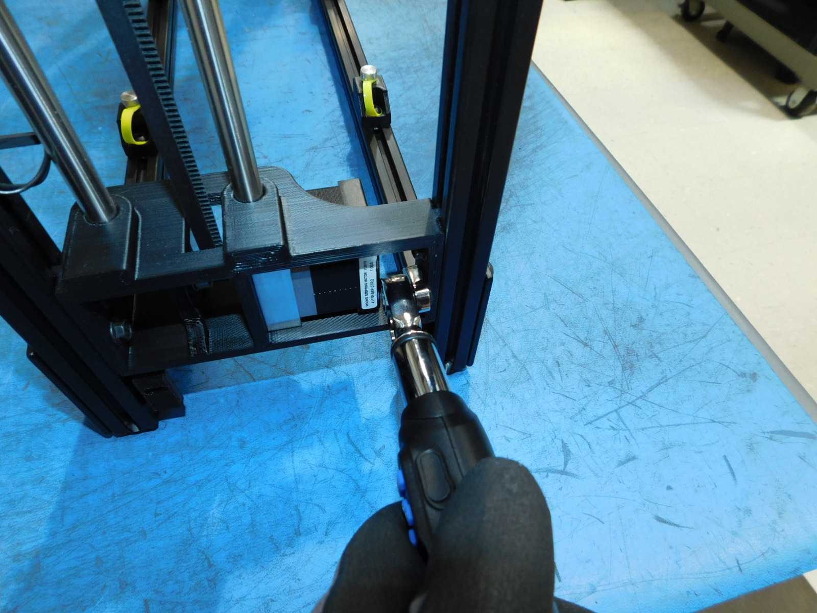
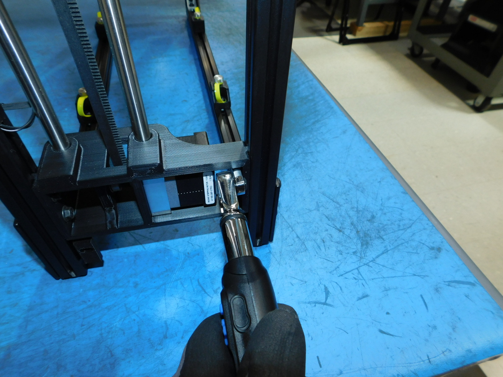
Torque all 8 Z-Lower to Frame fasteners [HD-BT0250] to 15in*lbs
Re-install the four frame feet [PP-GP0409] to the frame using four [HD-BT0073] M5 x 10 BHCS with four [HD-WA0040] M5 washer.
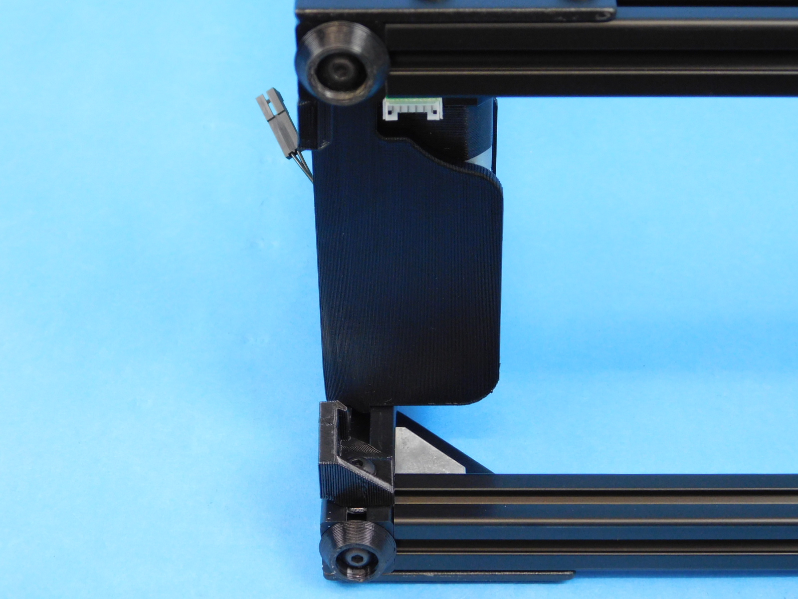
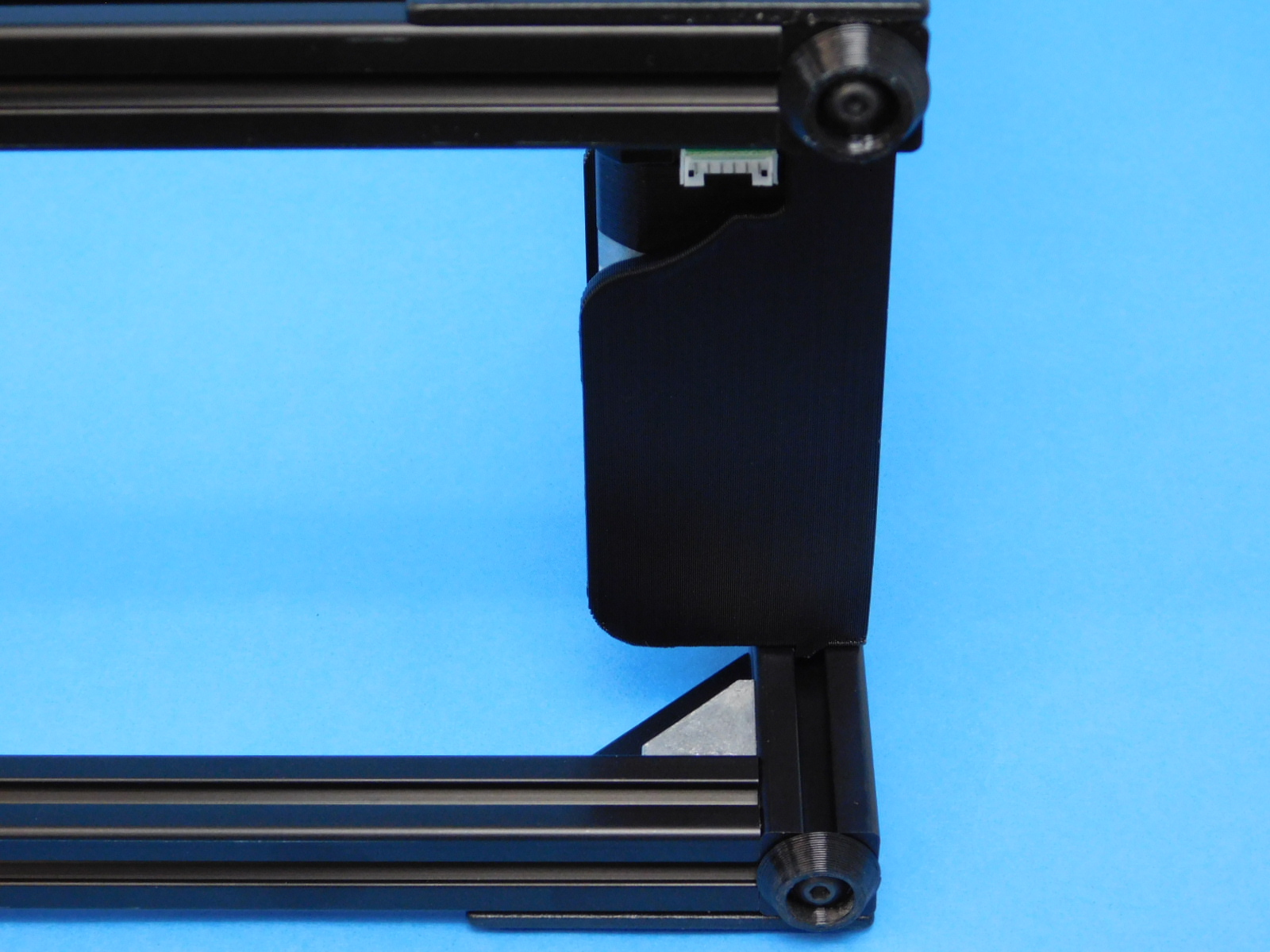
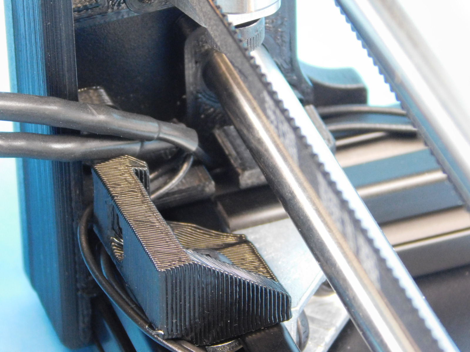
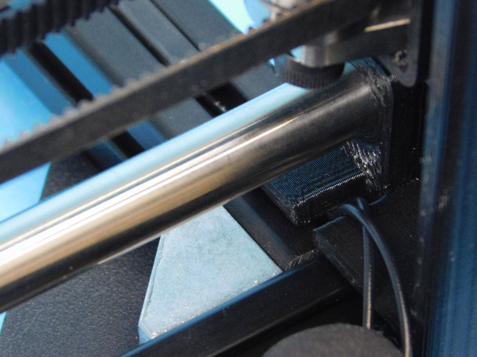
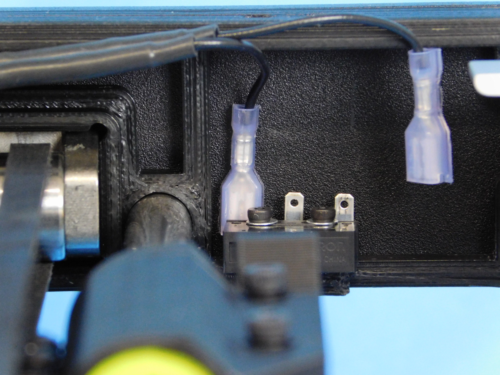
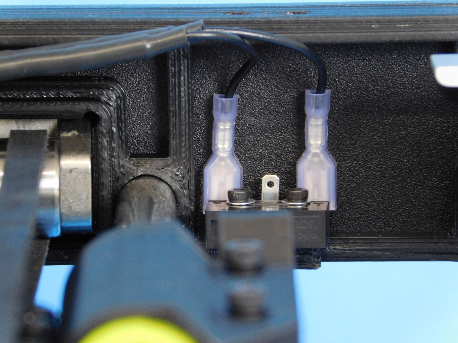
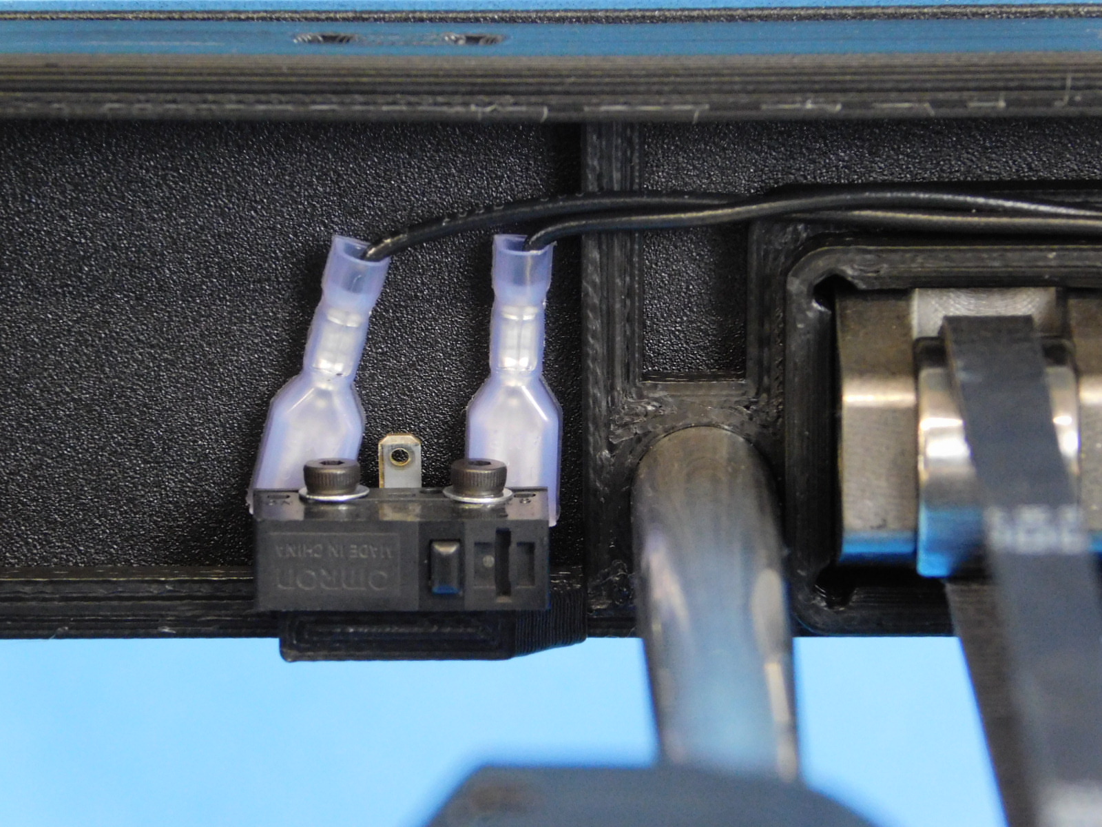
Plug in the wires for the z-max switches as shown.
There are no loose or un-torqued screws.
Spool Arm attached at correct height.
All four y-chassis mounts are attached and in the correct place with the spacing jig.
Z-max wires are plugged in and going to correct terminals.
All four feet are attached.