Open HardwareAssembly Instructions
Guides for installation and assembly of the LulzBot line of products made by Aleph Objects, Inc.
Guides for installation and assembly of the LulzBot line of products made by Aleph Objects, Inc.
Components Required:
1x- [AS-PR0101] Frame Assembly
1x- [AS-PR0086] X Carriage assembly
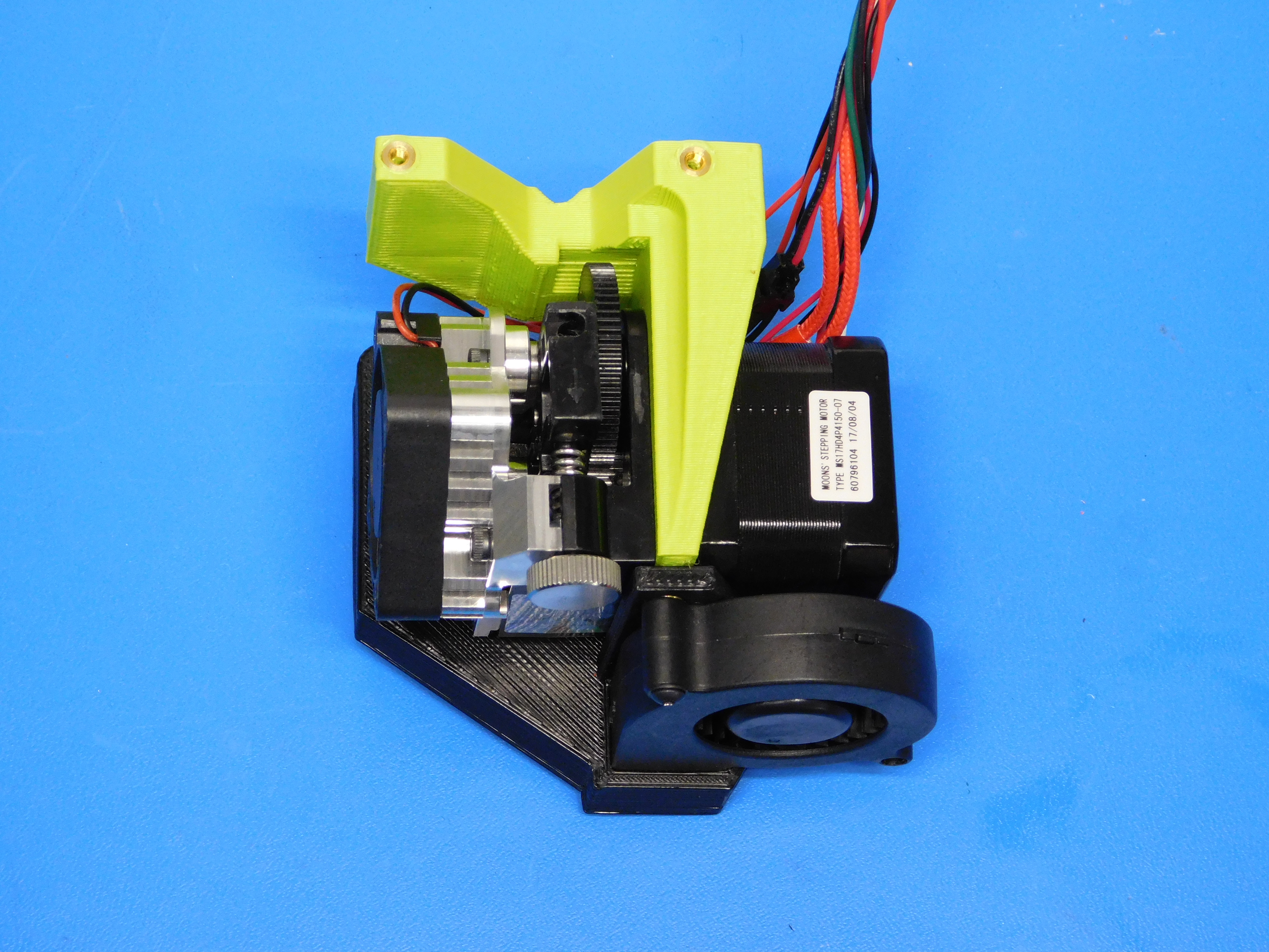
1x- [AS-TH0066] Titan Aero Assembly, Mini 2
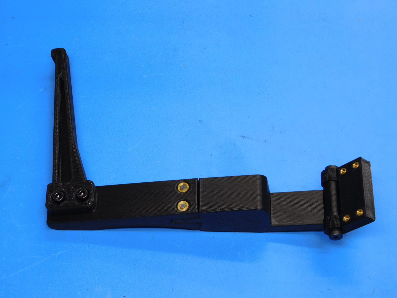
1x- [AS-PR0107] Spool Arm Assembly, Mini 2
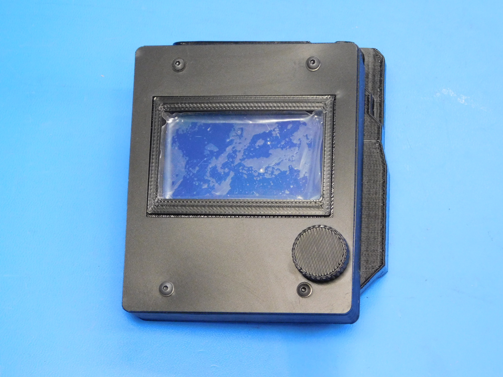
1x- [AS-EL0002] Mini 2 LCD Assembly
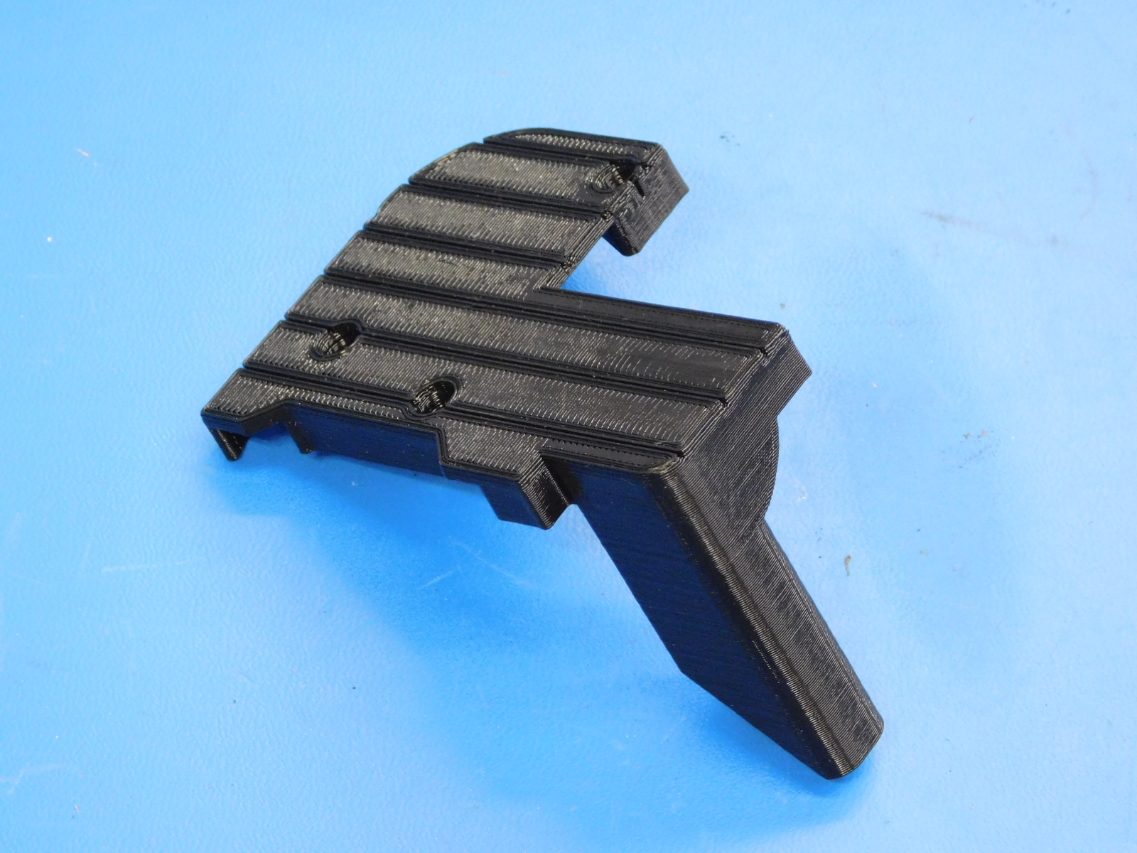
1x- [PP-GP0320] X carriage cap
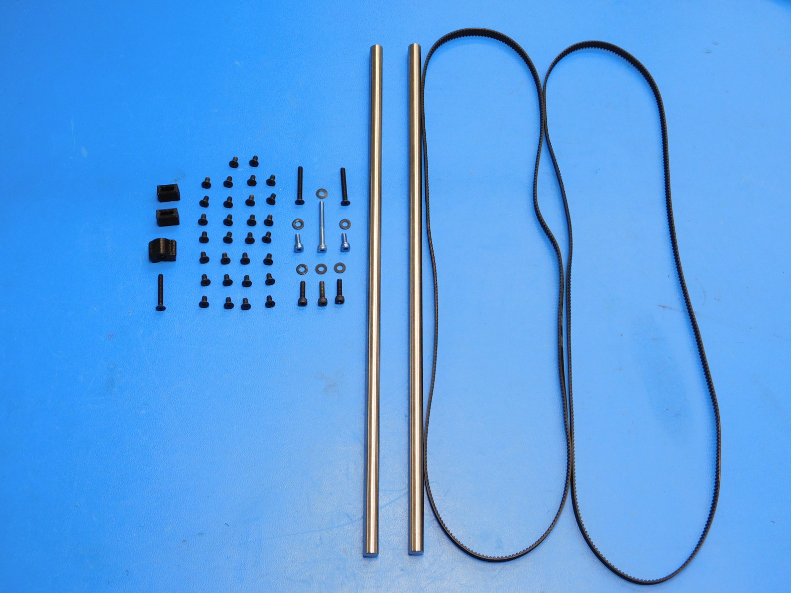
2x- [HD-RD0035] 8mm Smooth Rod, 315mm
3x- [HD-BT0039] M3x12 Socket Head Cap Screw
6x- [HD-BT0128] M3x6 Flat-Head Socket Cap Screw
6x- [HD-WA0038] M3 washer black oxide
2x- [HD-BT0211] M3x8 Blue Stainless SHCS
1x- [HD-BT0210] M3x30 Blue Stainless SHCS
2x- [HD-BT0206] M3x25 FHCS
1x- [HD-BT0204] M3x22 FHCS
2x- [HD-BL0033] GT2 Timing Belt
2x- [PP-GP0307] Belt Tensioning Collar
1x- [PP-GP0333] Belt Tensioner Post
Tools Required:
Cutters
Needle nose pliers
Phillips screwdriver
508C Sonic Tension Meter
2.5 mm hex driver
2.0 mm hex driver
1.5 mm hex driver
3in-lbs torque driver
5in-lbs torque driver
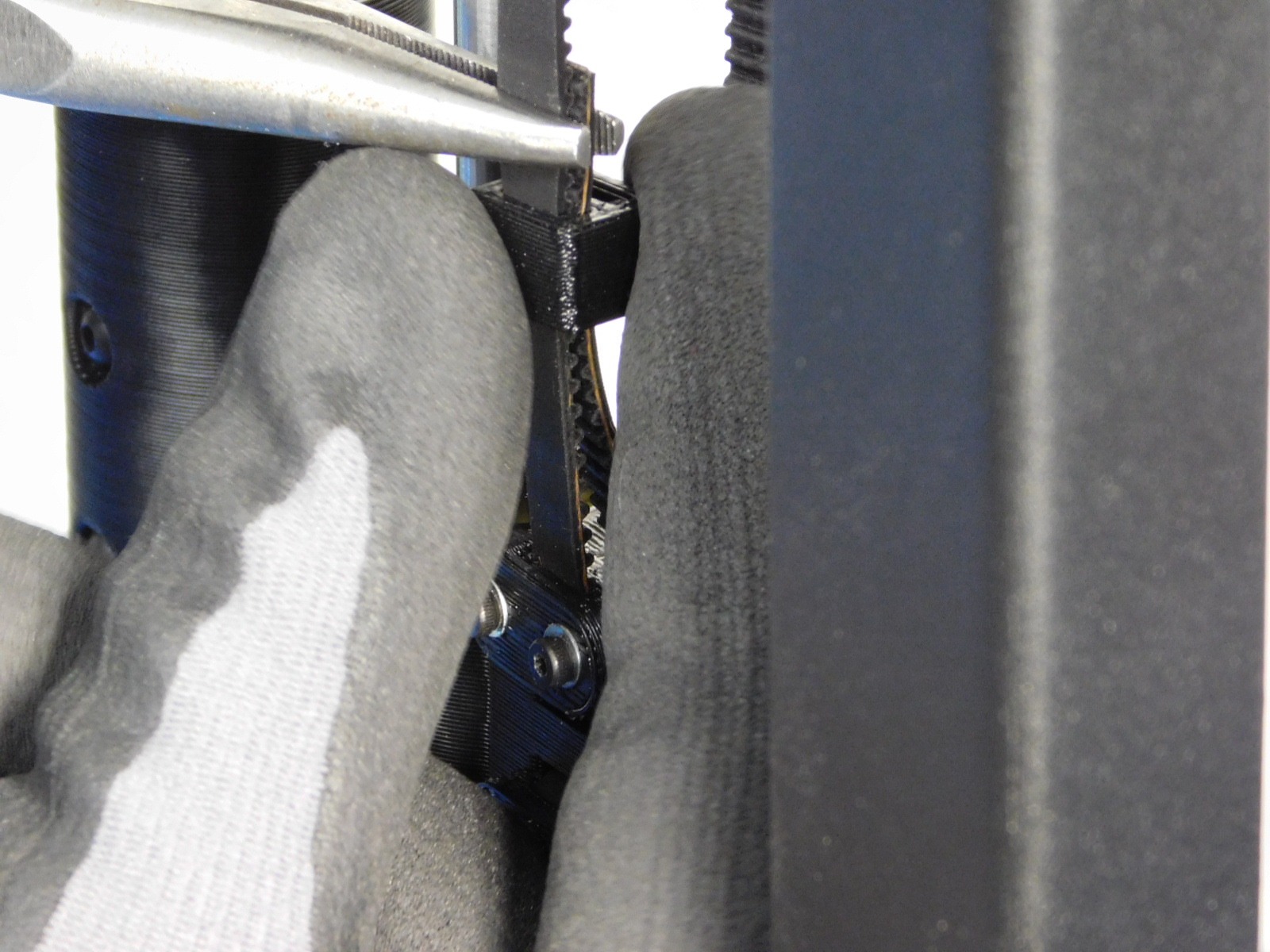
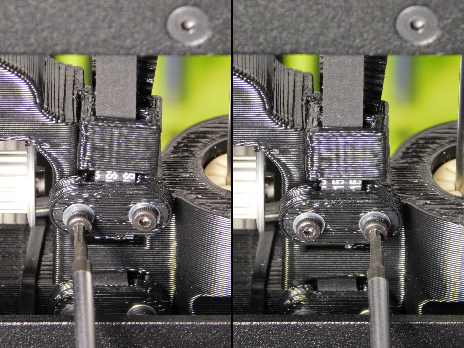
On the X-End Idler, loosen the upper Z-Belt Clamp using a 1.5mm Hex driver.
Grip the end of the belt above the X-End Idler and twist to apply tension to the Z-Belt.
Tighten the two M2x6 SHCS on the upper Z-Belt Clamp to secure the Z-Belt.
Use the 508C Sonic Tension Meter to ensure the belt is tensioned sufficiently.
For complete instructions regarding the 508C Sonic Tension Meter use with Mini 2, see THIS OHAI
Acceptable tension for the Z-Belts is 35-45N
For proper measurement results, obtain measurements with the Z-axis near mid travel, ensuring the section of belt being measured is not contacting printed parts; this will provide incorrect tension readings.
Setting number 3 on your 508C Meter is set-up with proper parameters for the Z-axis, if unsure contact your line lead, supervisor, or MER Technician.
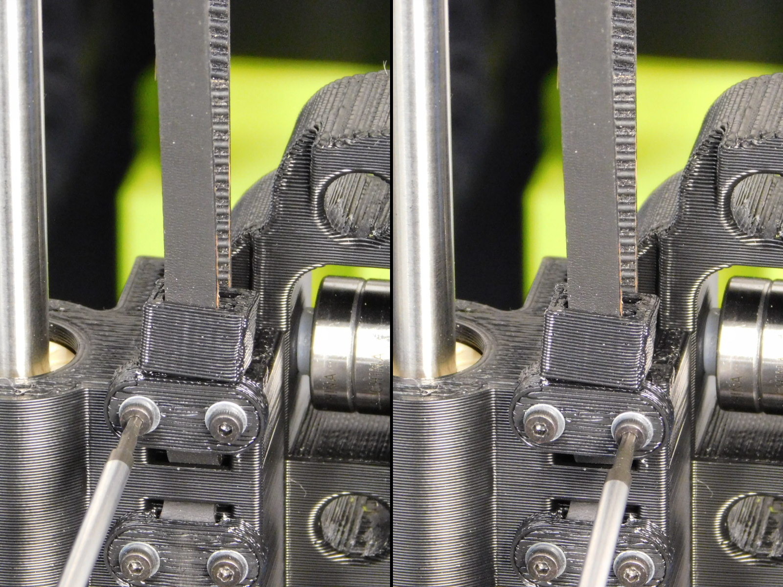
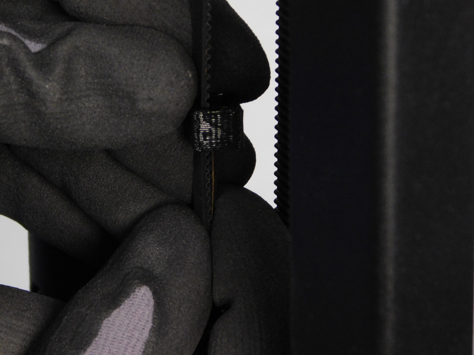
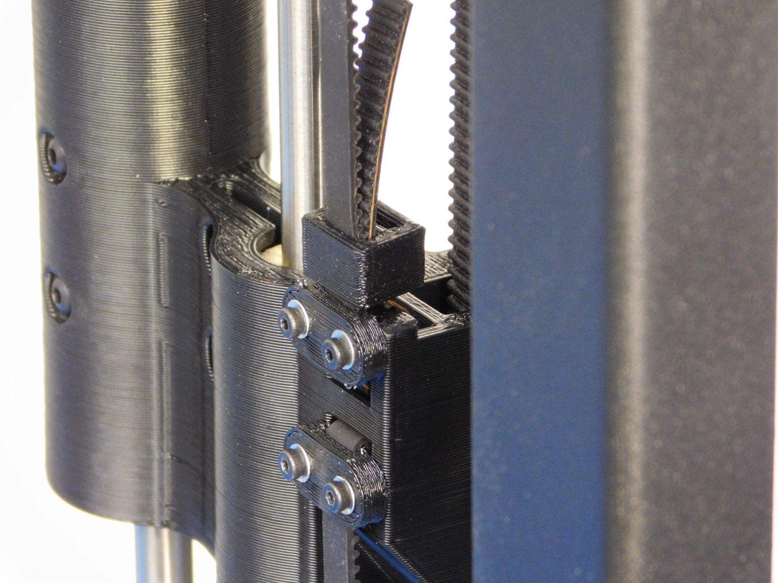
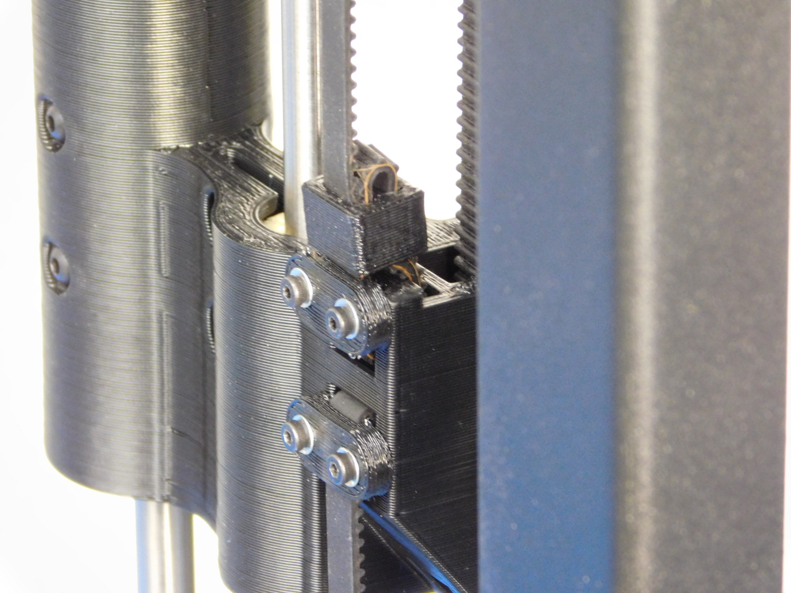
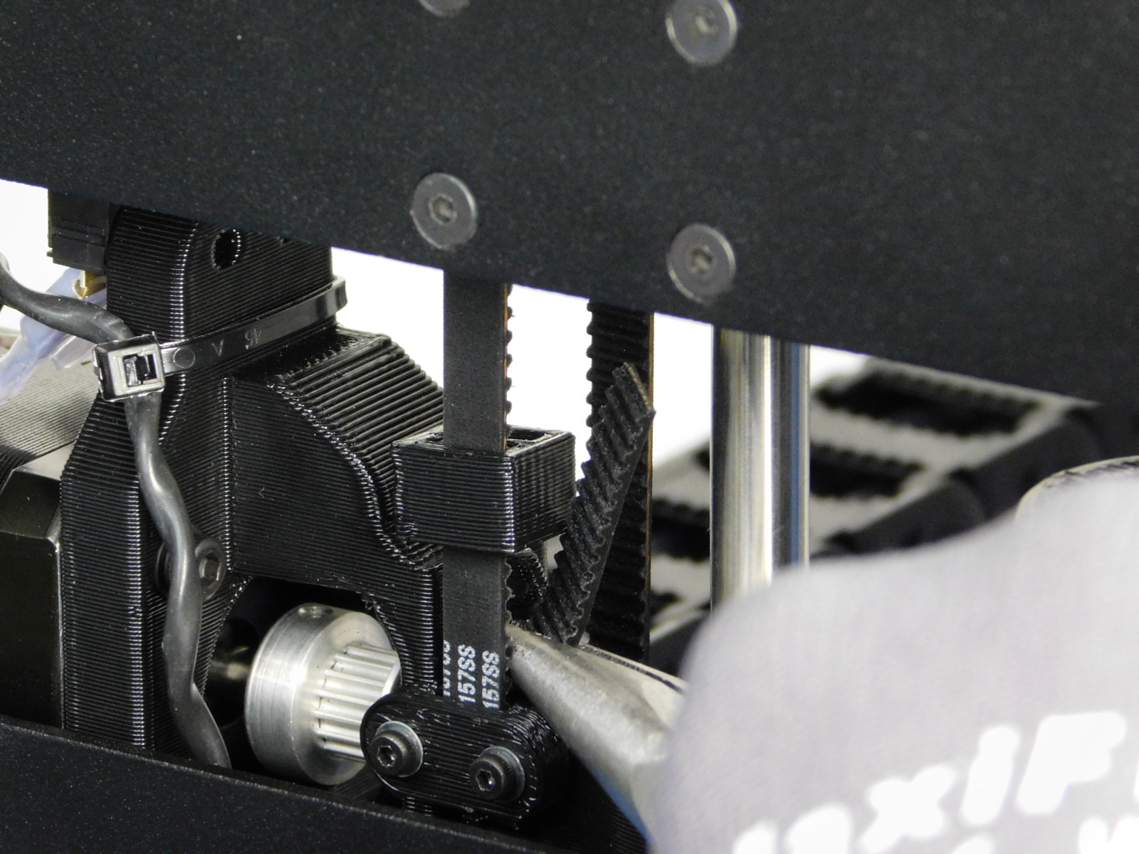
Slide the Belt Tensioning Collar [PP-GP0307] down over the end of the belt to capture the slack. Push it as close to the X-End Idler printed part as possible.
Trim the excess belt straight with the teeth of the belt, leaving ~5mm above the belt tensioning collar.
Repeat this process on the X-End Motor side;
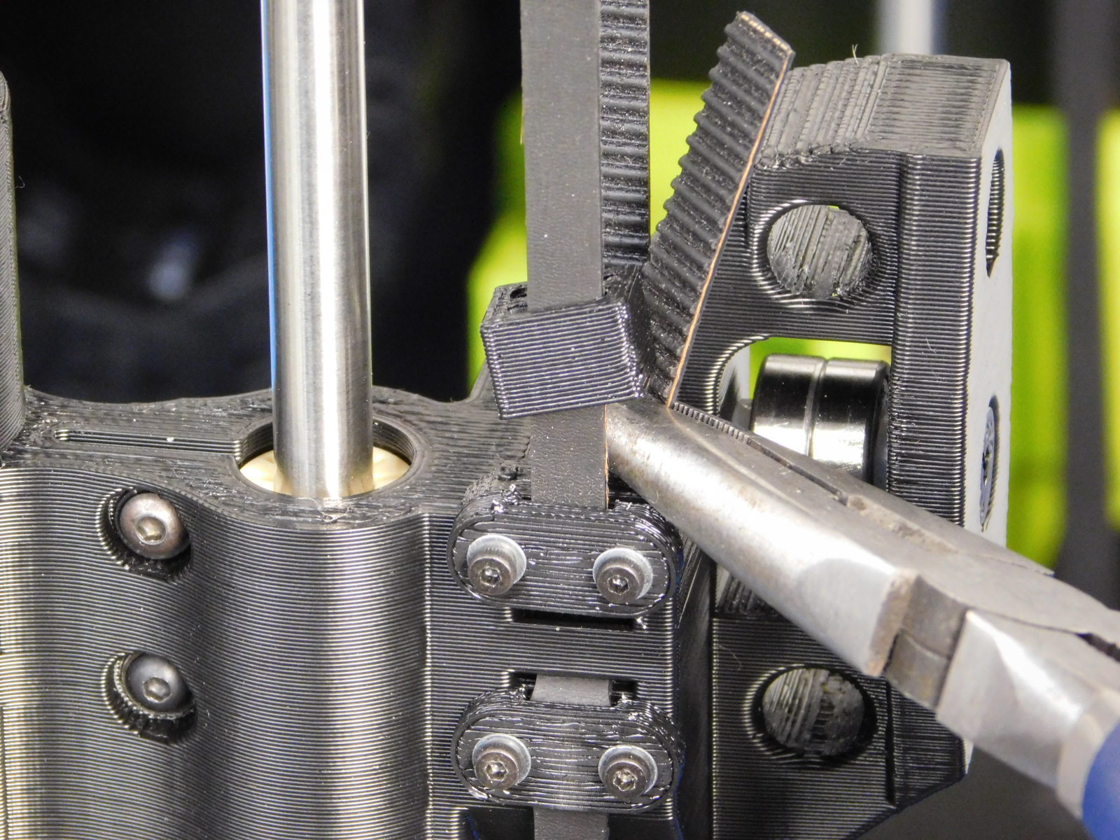
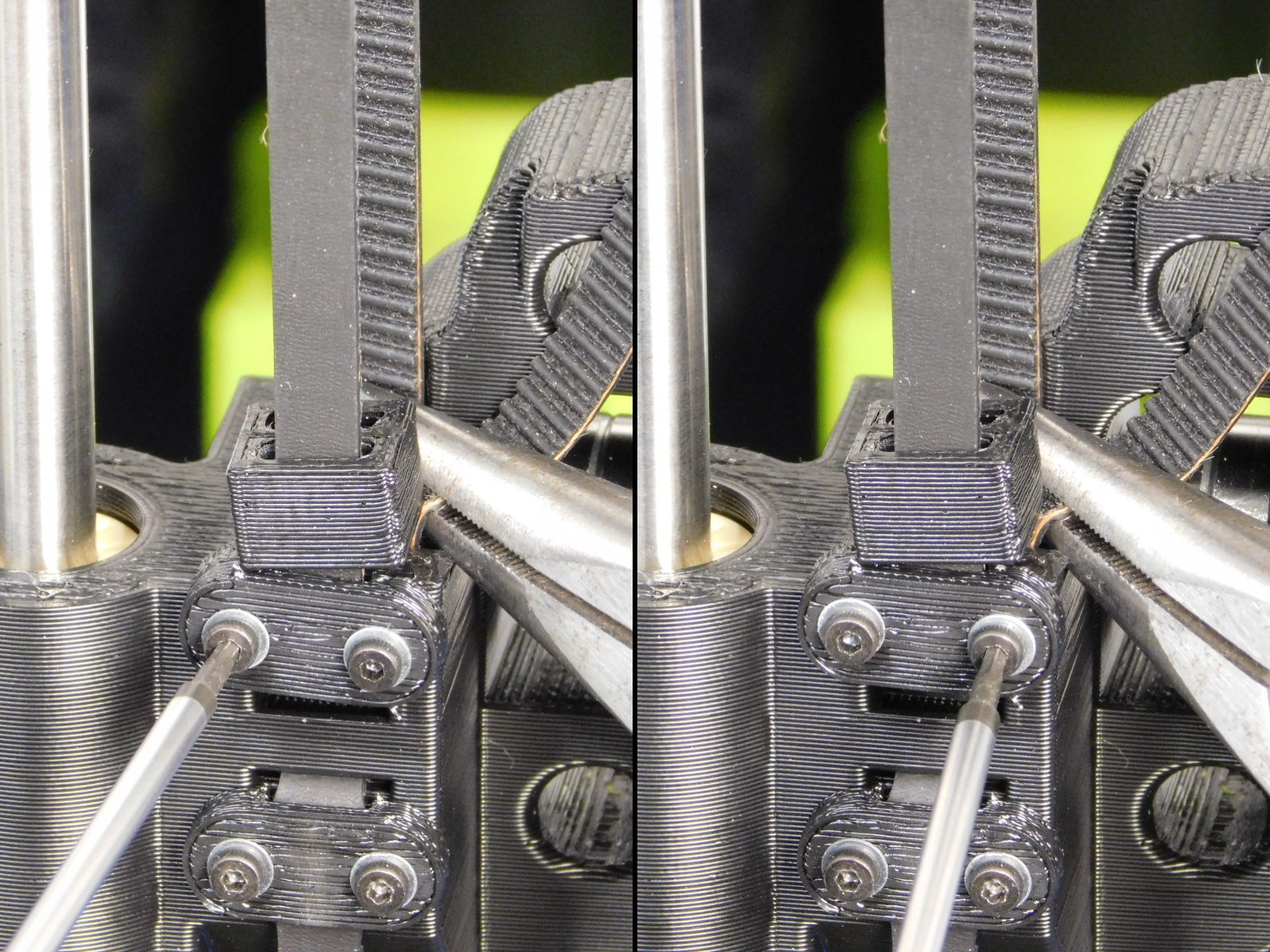
Grip the bottom of the X-End Motor printed part and lift until the upper Z-Belt Clamp is visible through the cut-out in the left frame plate.
Loosen the two M2x6 SHCS securing the upper Z-Belt Clamp until the belt is able to move.
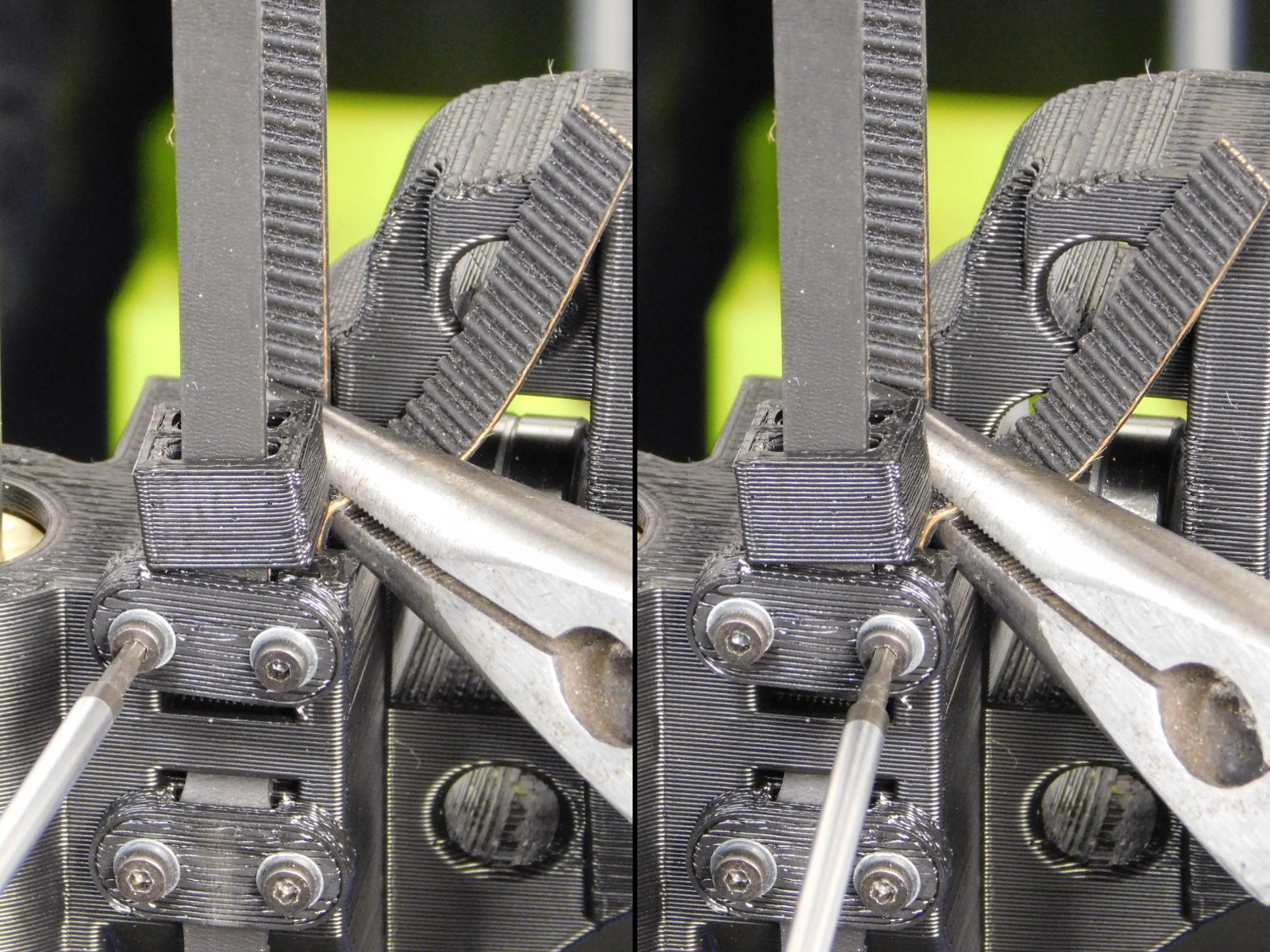
Grip the end of the belt on top of the X-End Motor printed part and twist to apply tension to the Z-Belt.
Tighten the two M2x6 SHCS on the upper Z-Belt Clamp to secure the Z-Belt.
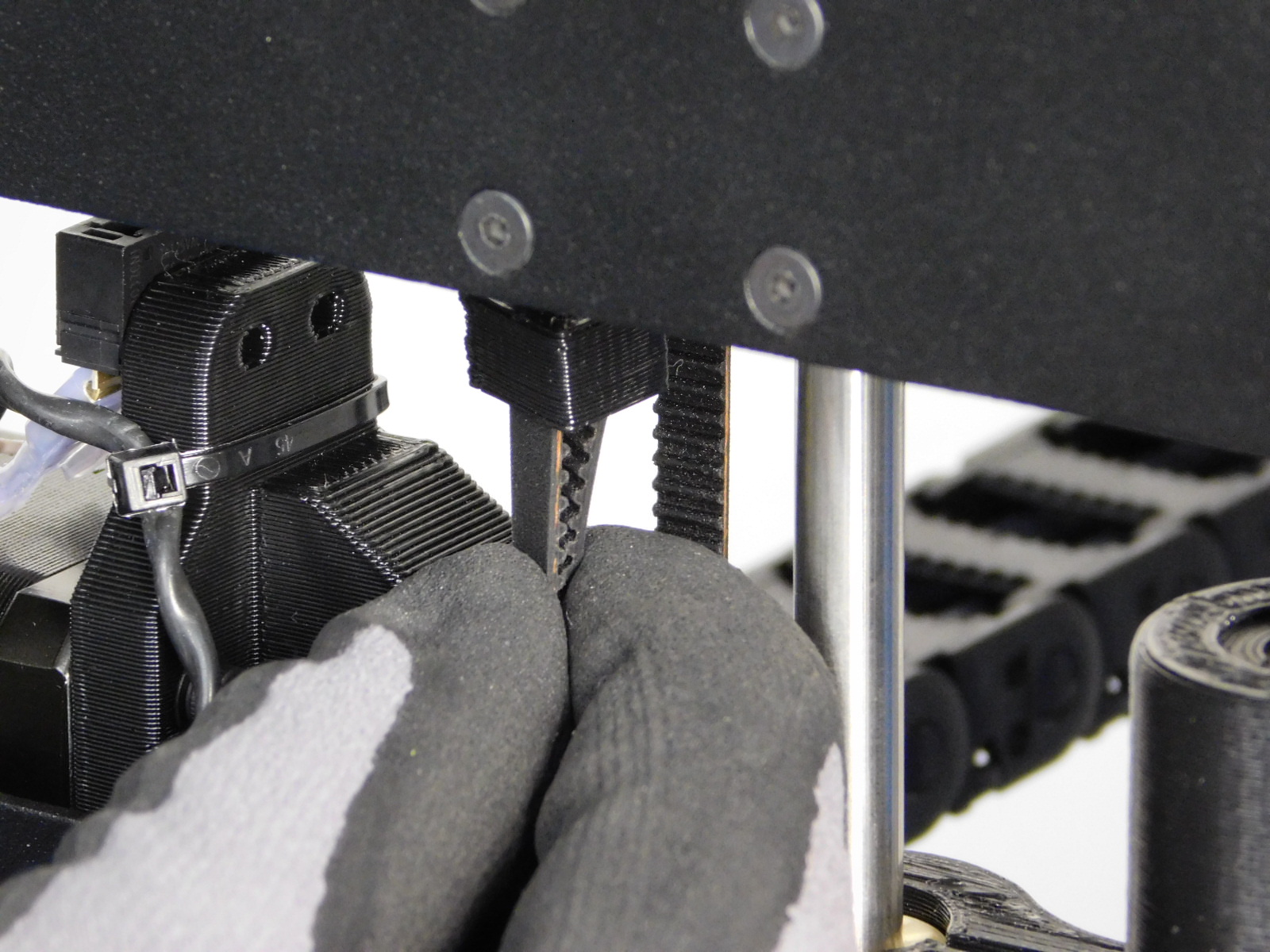
Slide the Belt Tensioning Collar [PP-GP0307] down over the end of the belt to capture the slack. Push it as close to the X-End Motor printed part as possible.
Trim the excess belt straight with the teeth of the belt, leaving ~5mm above the belt tensioning collar.
Use the 508C Sonic Tension Meter to ensure the belt is tensioned sufficiently.
Acceptable tension for the Z-Belts is 35-45N. It is best to set the belt towards the top of the range, because they will settle to a lower tension after burn-in.
For proper measurement results, obtain measurements with the Z-axis near mid travel, ensuring the section of belt being measured is not contacting printed parts; this will provide incorrect tension readings.
Setting number 3 on your 508C Meter is set-up with proper parameters for the Z-axis, if unsure contact your line lead, supervisor, or MER Technician.
Both Z-Belts should be as close to each other in tension as possible.
Torque Z-Belt Clamp fasteners to 2in*lbs
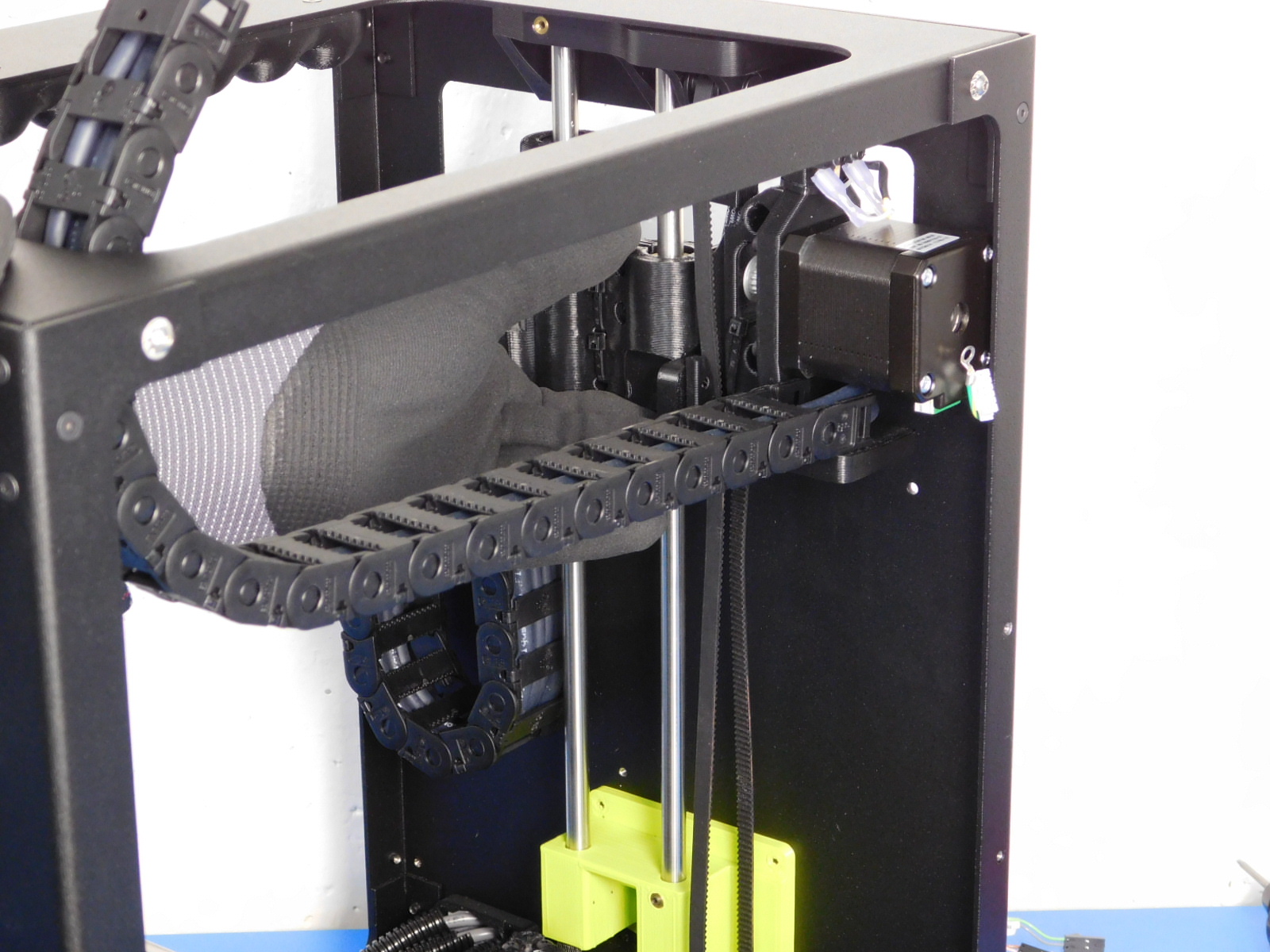
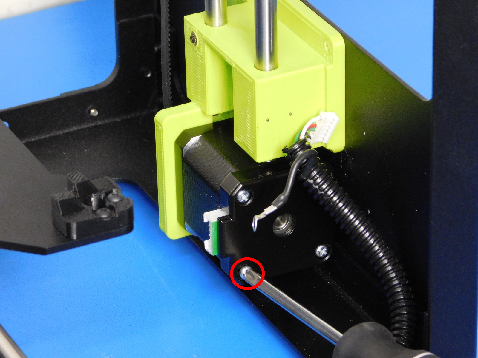
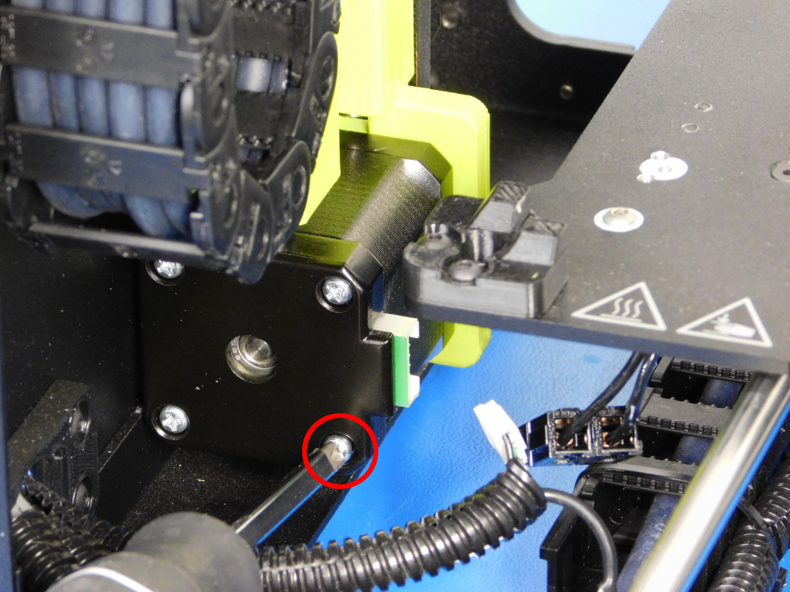
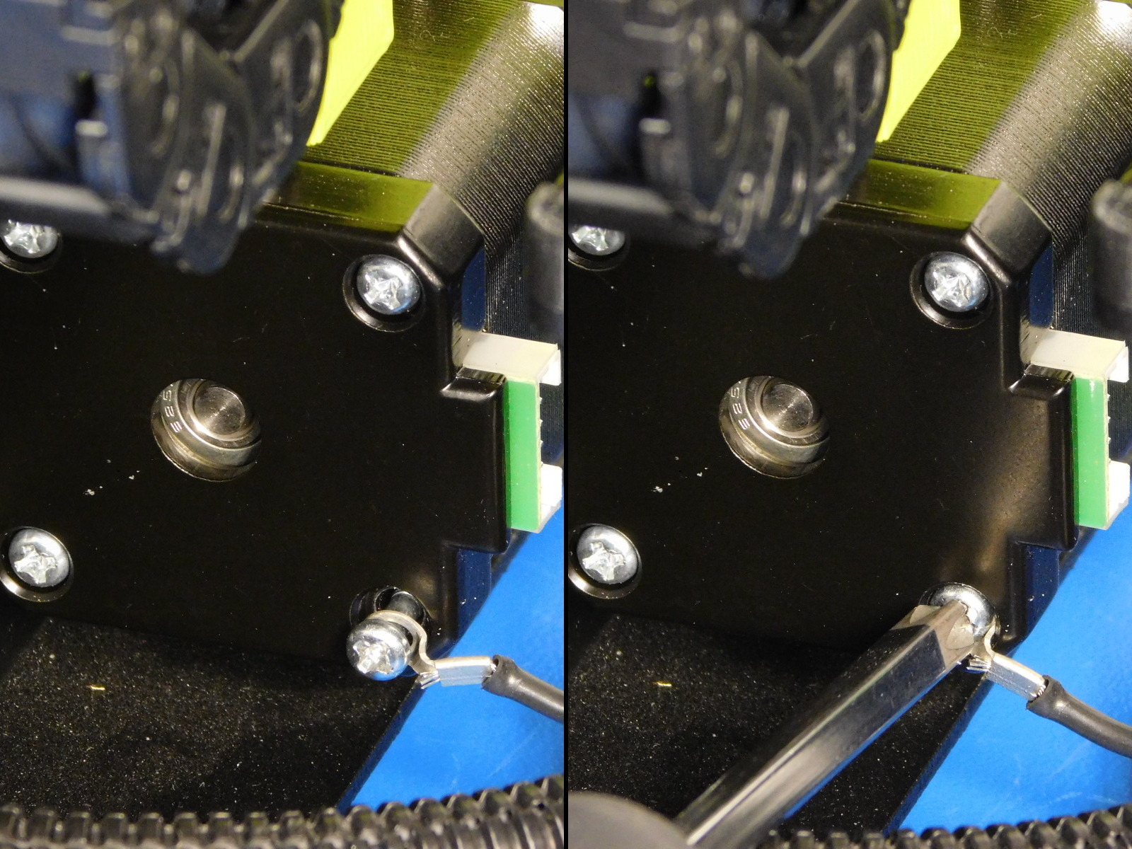
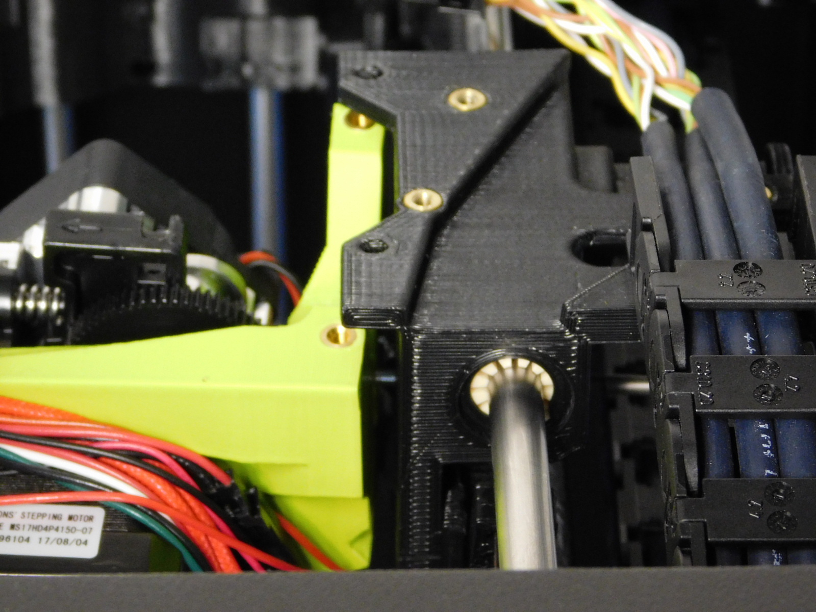
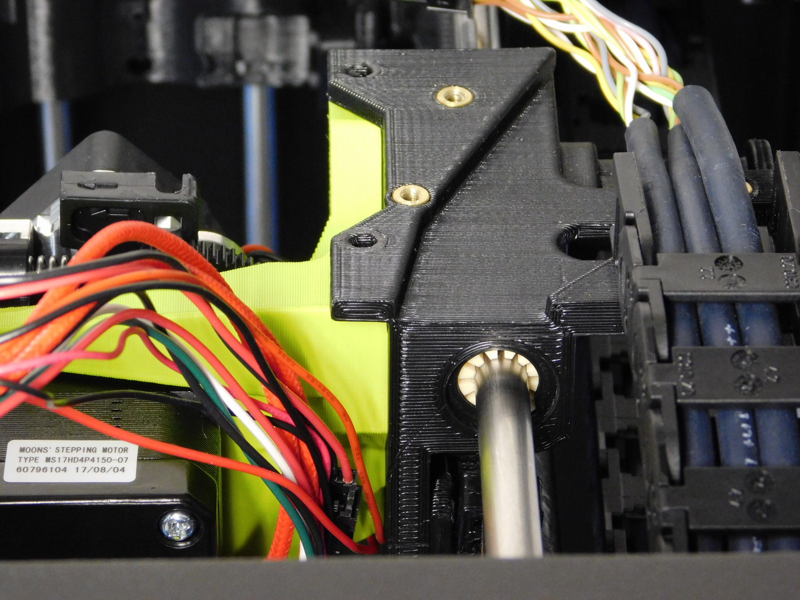
Completely remove the Z-Right motor housing screw below the connector using a P2 Phillips screwdriver
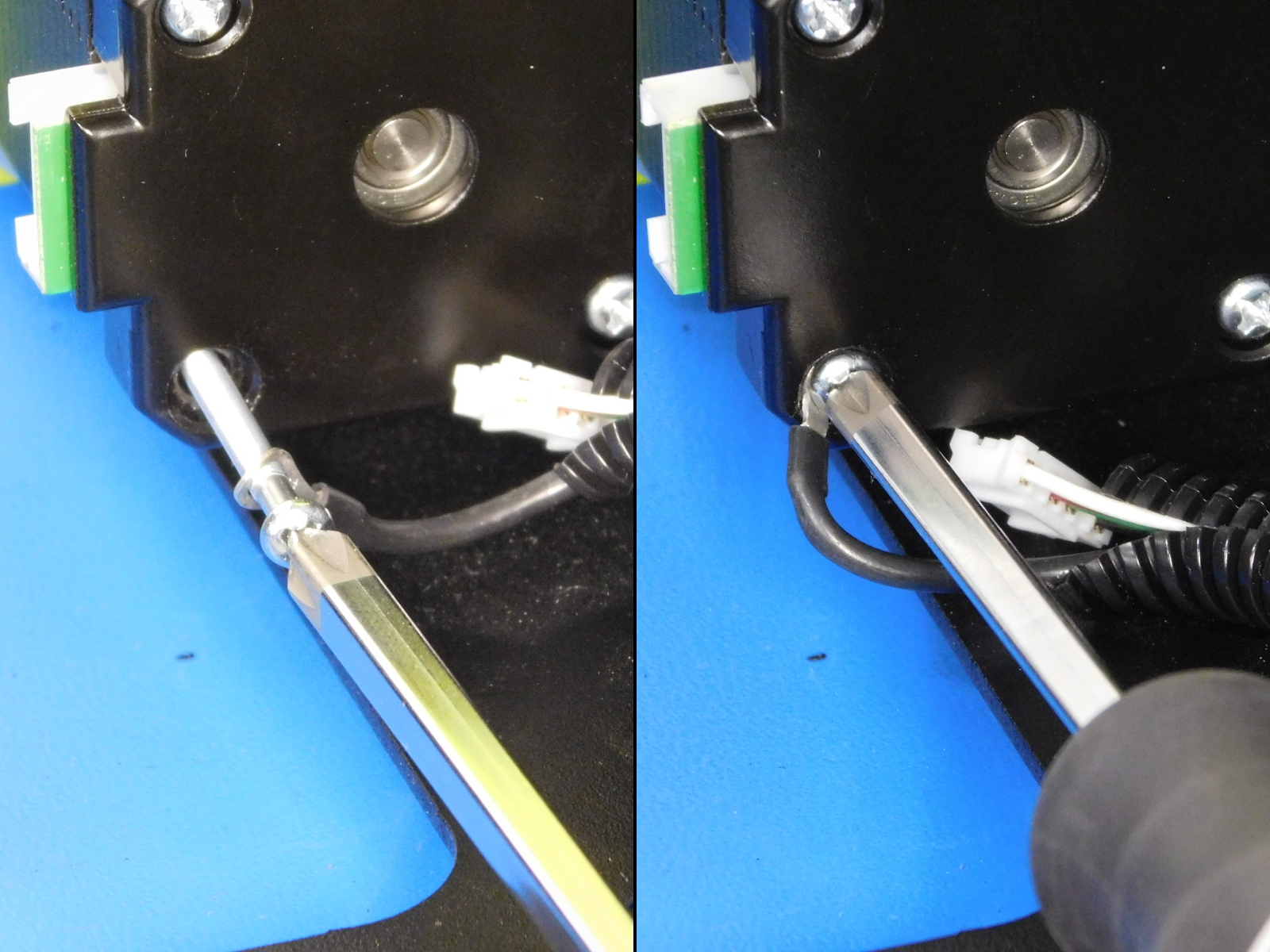
Insert the right motor's housing screw through the ring terminal of the Z-Right Motor cable, reinstall the housing screw into the Z right motor capturing the ring terminal.
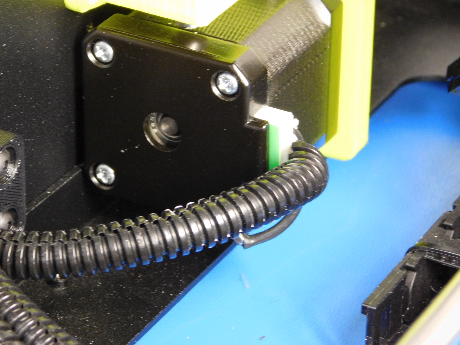
Ensure the screw becomes recessed and tight.
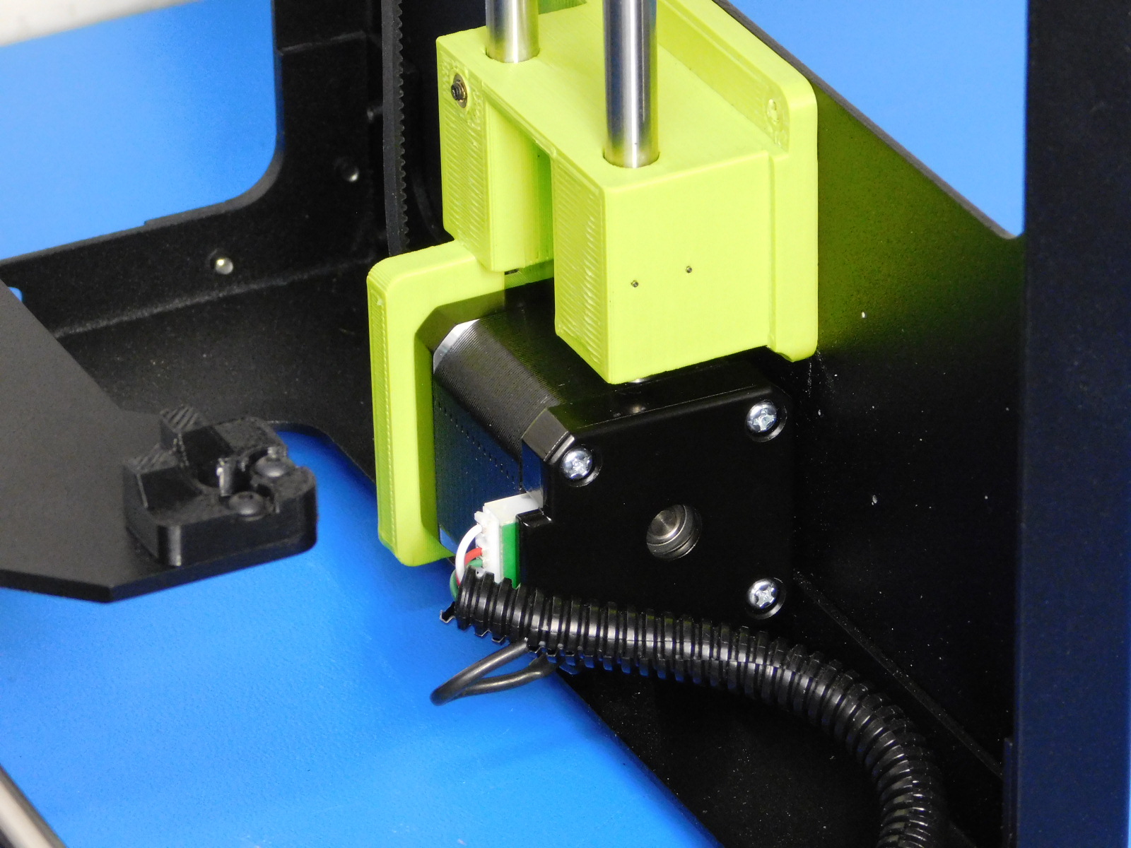
Connect the JST connector to the Z-Right Motor
Completely remove the Z-Left motor housing screw below the connector using a P2 Phillips screwdriver
Insert the left motor's housing screw through the ring terminal of the Z-Left Motor cable, reinstall the housing screw into the Z-Left motor, capturing the ring terminal.
Ensure the screw becomes recessed and tight.
Connect the JST connector to the Z-Left Motor
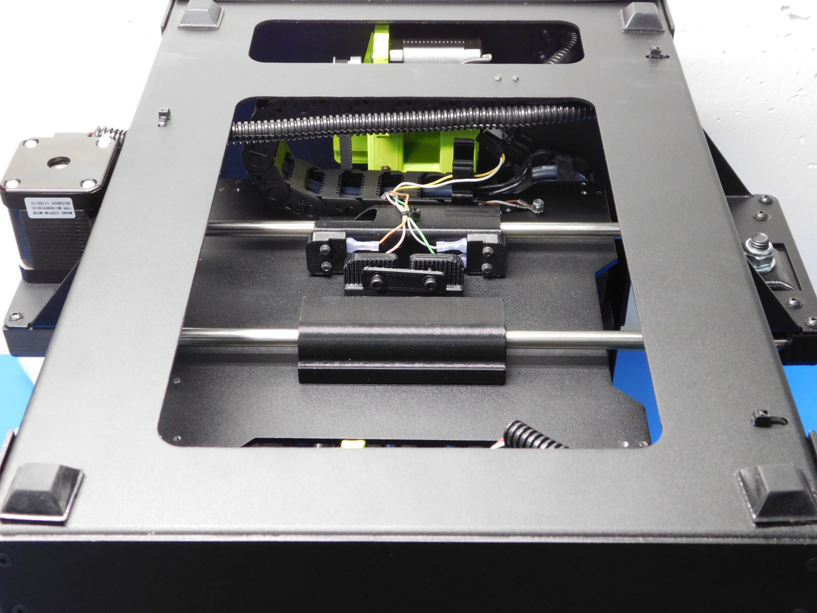
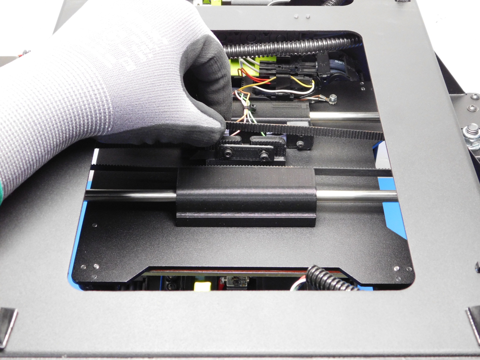
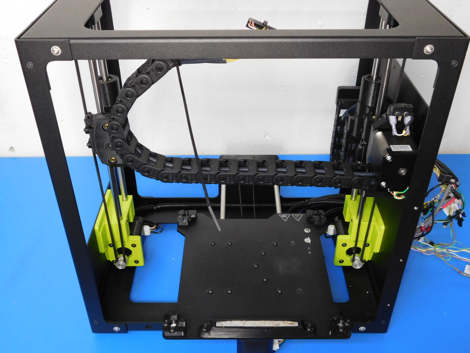
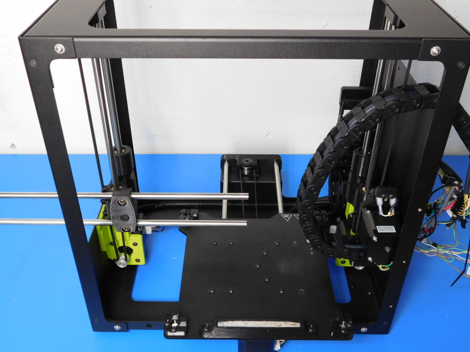
Flip the assembly upside down so that it rests on the top frame plate with the Y-Idler to your right.
Cut the Timing Belt [HD-BL0033] at an angle to assist feeding through the Y-Idler.
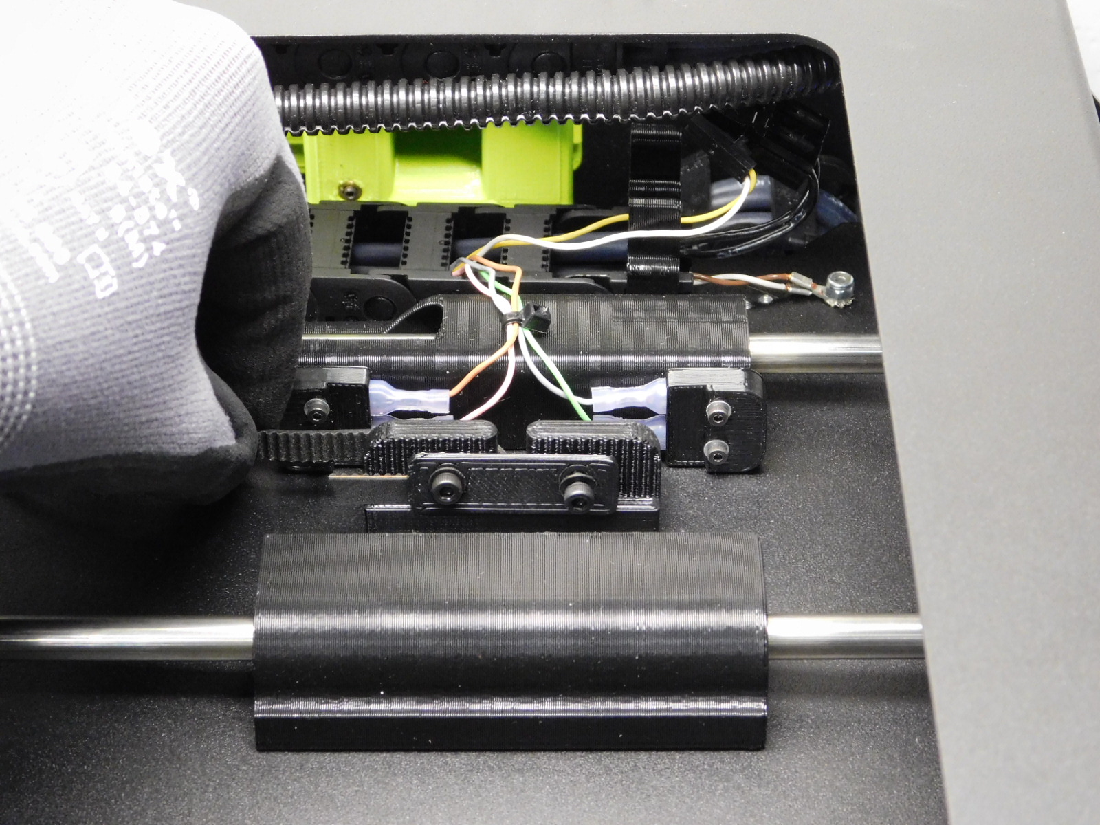
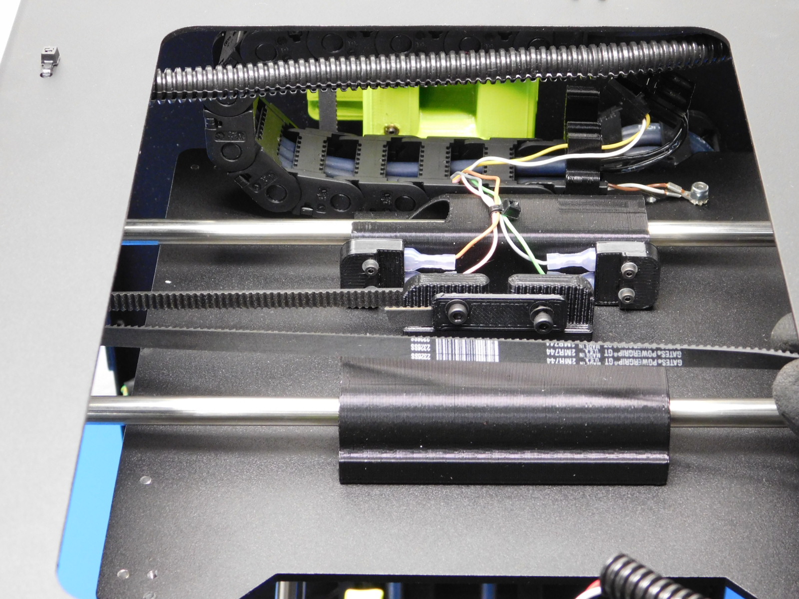
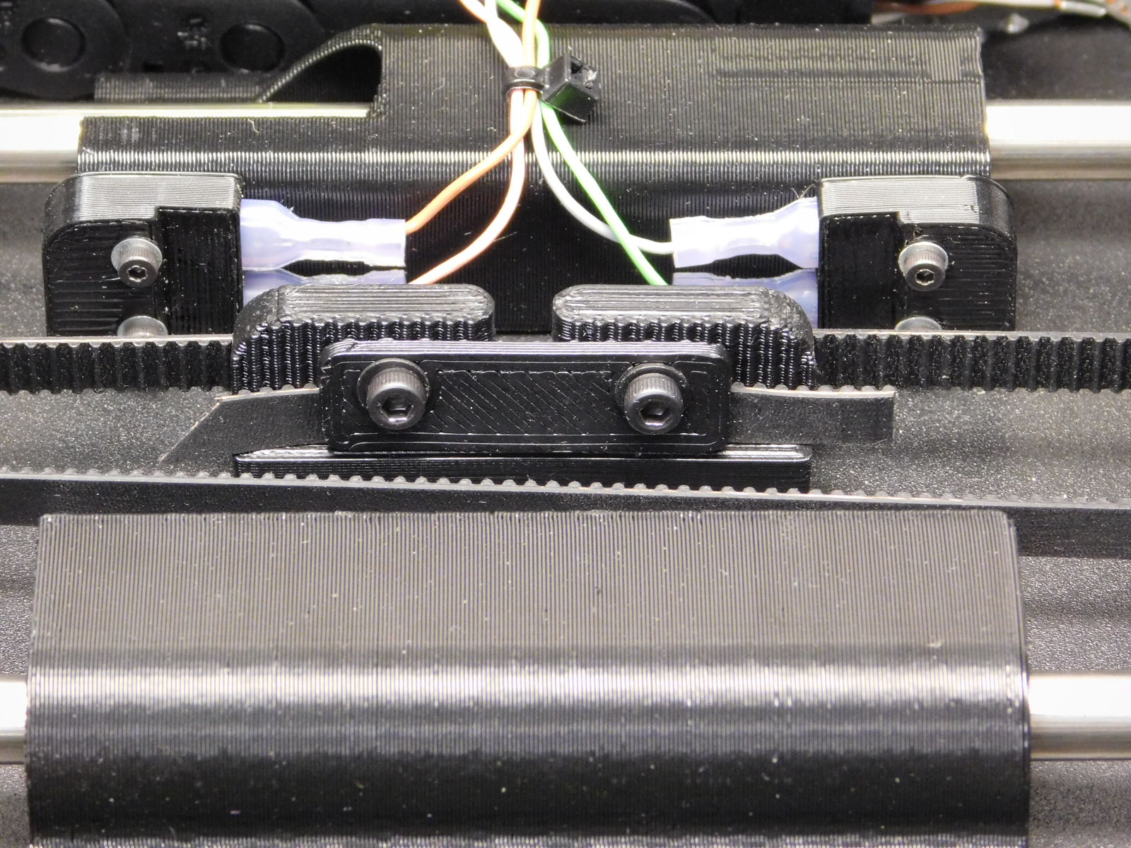
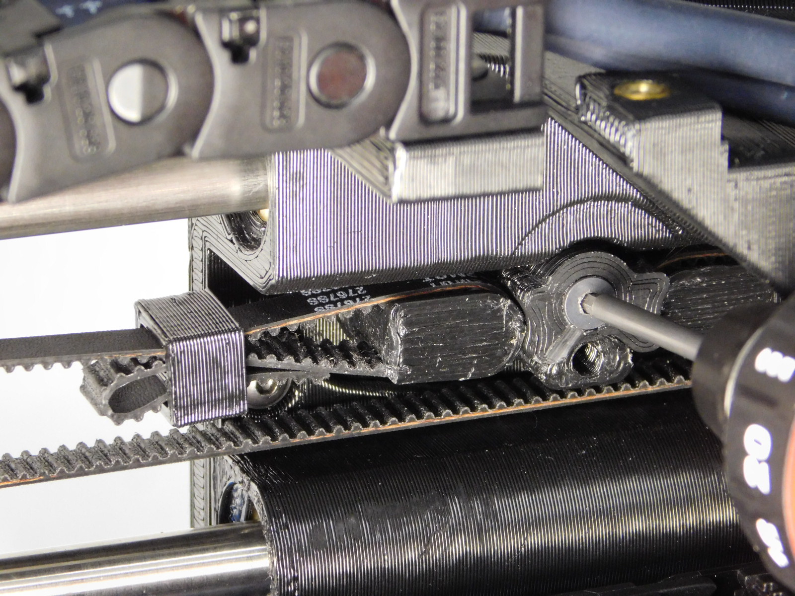
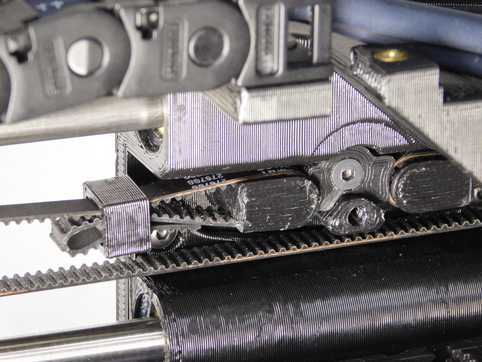
Loop the belt around the left belt mount post as pictured.
Run the timing belt with the teeth on the inside around the timing pulley, then run the timing belt around the idler bearings and back to the belt mount
Loop the belt around the right belt mount post
Tighten the left M3x12 SHCS to firmly hold the belt.
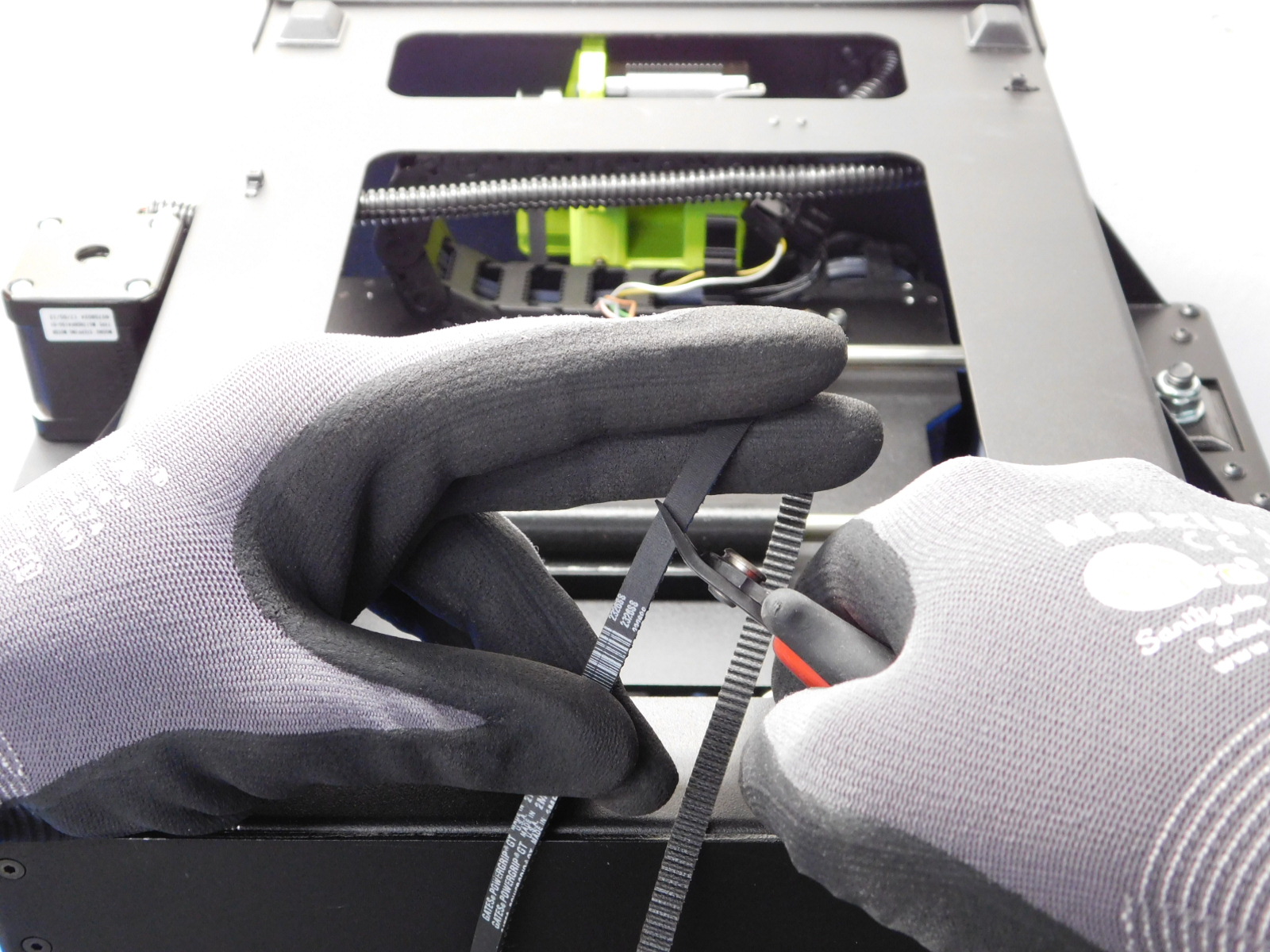
Grab the loose end of belt (on the right) with a pair of needle nose pliers and pull the belt tight, tighten the right side of the Belt clamp
Use setting number 2 on the 508C Sonic Tension Meter to check the tension in the belt (see OHAI) When measuring the mini 2 belt tensions on the X and Y, push the carriages to the idler side.
The tension should be between 23-27 Newtons. It is best to set the belt towards the top of the range, because they will settle to a lower tension after butn-in.
Trim the excess timing belt, leaving about 20mm on each side.
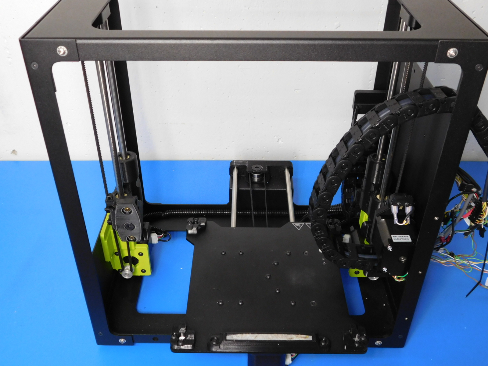
Flip the assembly back upright with the back of the machine facing you.
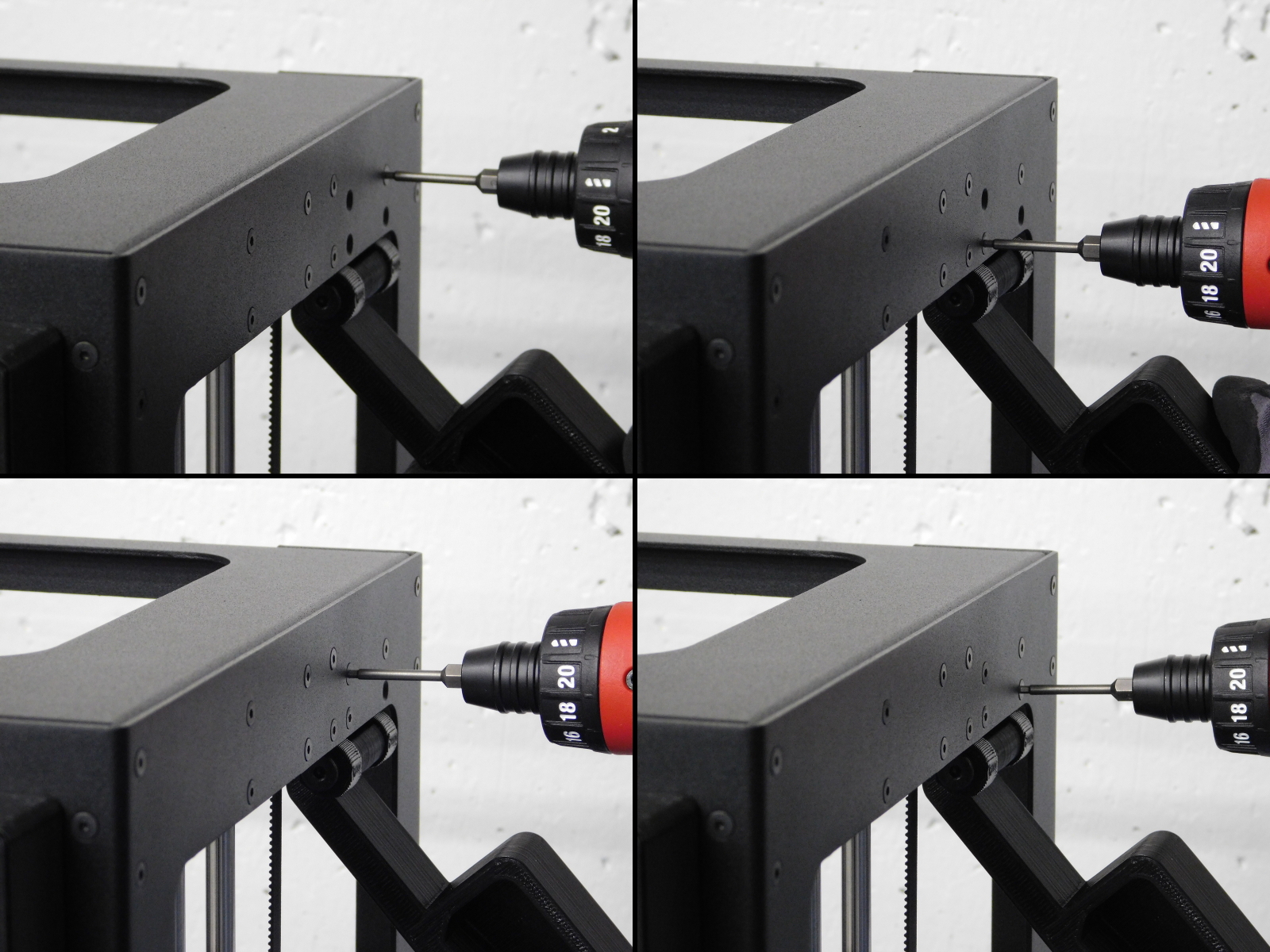
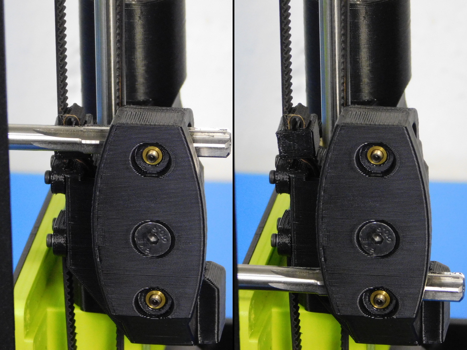
Use a 8mm part reaming tool to ream the smooth rod holes of the X-End Idler.
Push both Left & Right X-Ends down against the Z-Lowers so that they are level with each other.
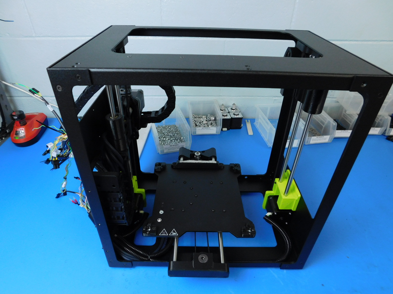
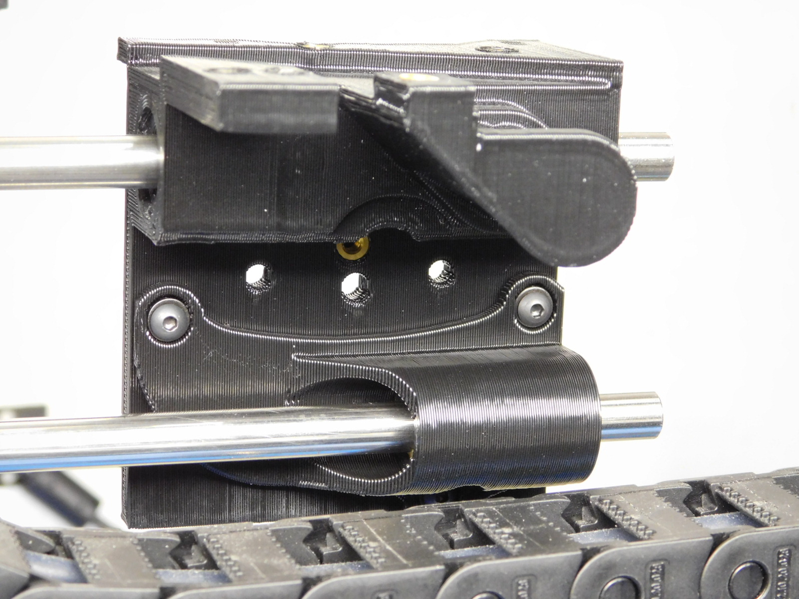
Slide the two smooth rods through the X End idler assembly and the X carriage assembly as pictured
Insert the ends of the Smooth Rods into the X-End Motor assembly
It is important not to push too far as too much distance between the X-Ends will cause the Z-Axis to bind at the top. Make sure the X-Ends remain relaxed with no outward tension from the Smooth Rods. The ends of the smooth rods should protrude an even distance from the right side of the X-End Idler printed part.
Tighten the set screws already installed in the rear of the X-End Idler; torque to 3in*lbs
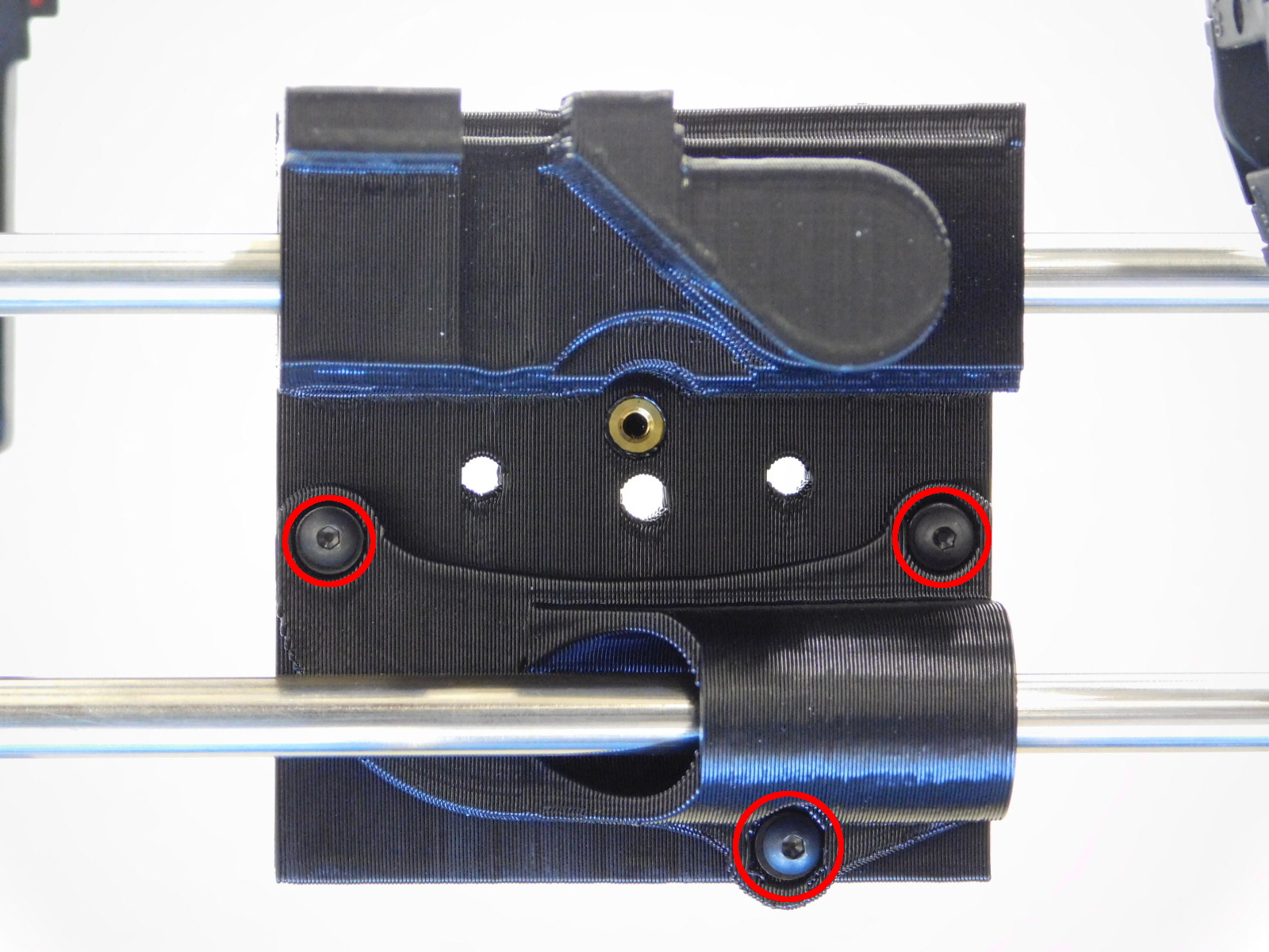
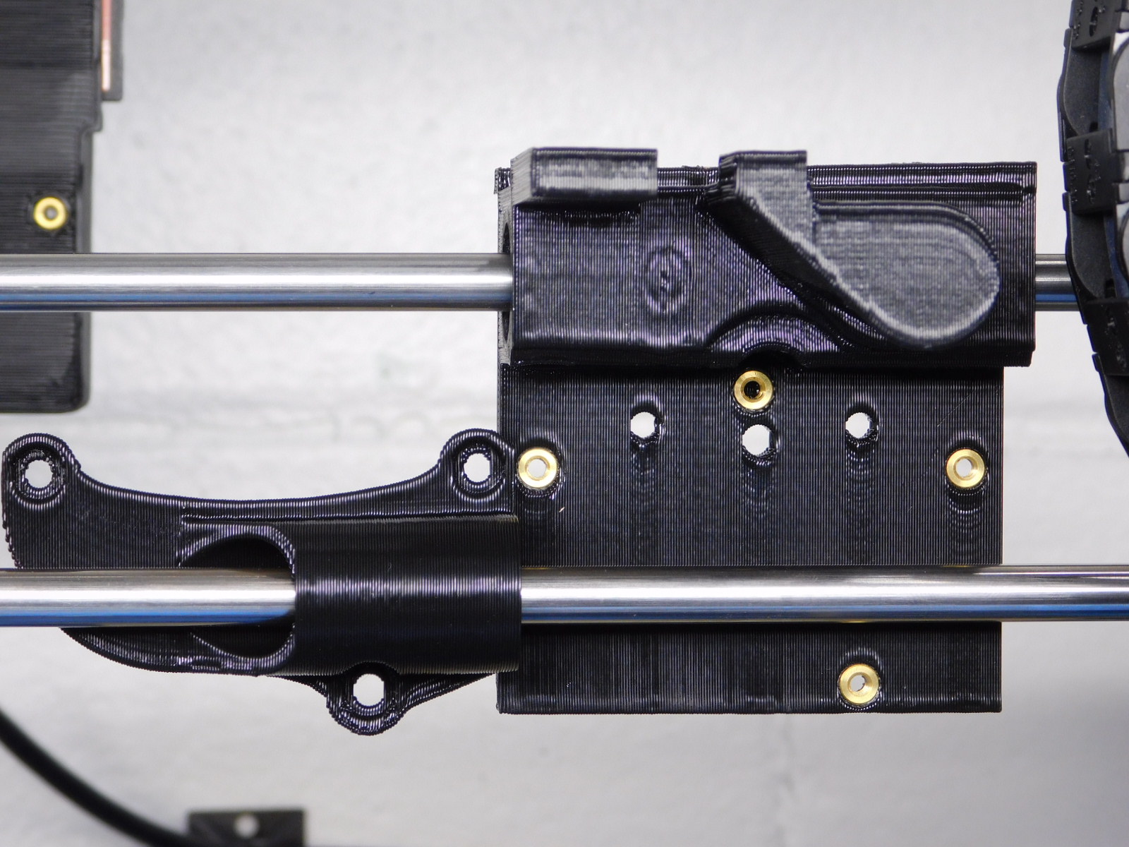
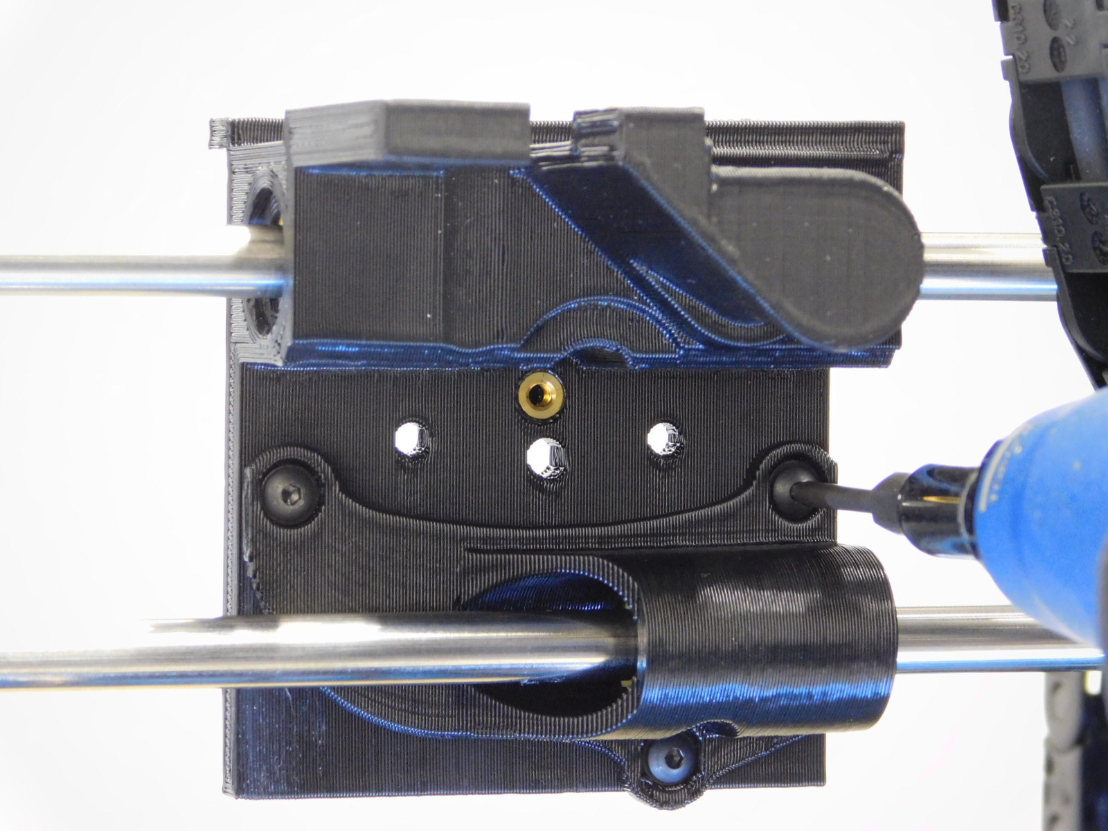
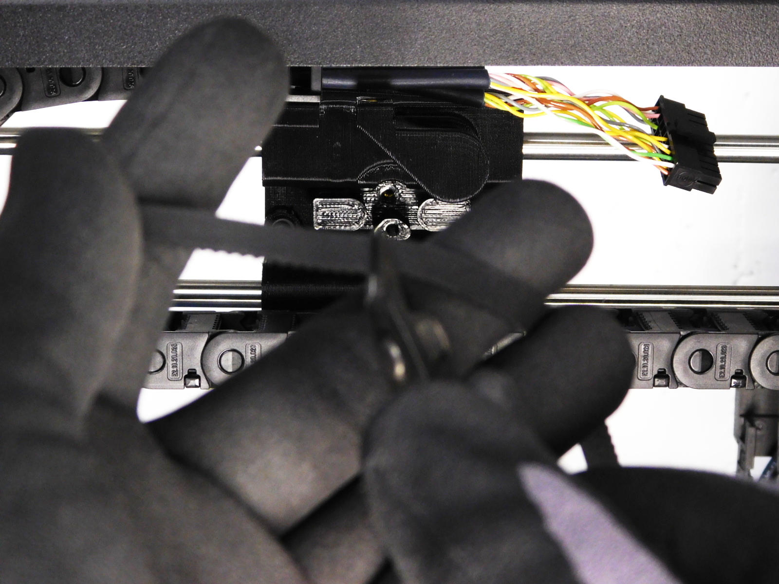
Using a 2mm Hex Driver, remove the four M3x8 BHCS securing the X-Bearing Holder to the X-Carriage, slide the X-Bearing Holder to your left on the smooth rod.
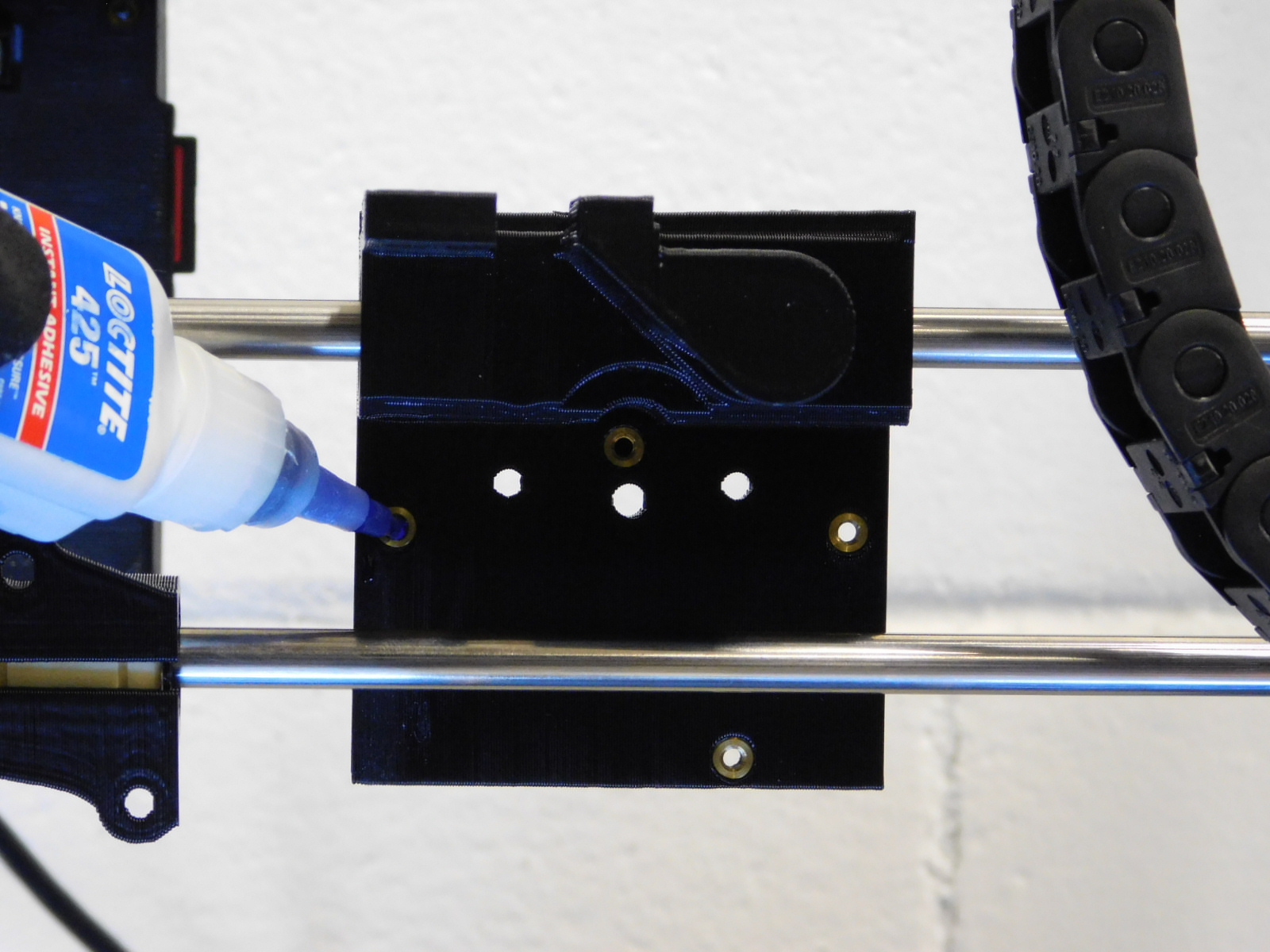
Using an eyedropper, apply a small amount of Loctite® 425™ to the now exposed M3 inserts on the back of the X-Carriage.
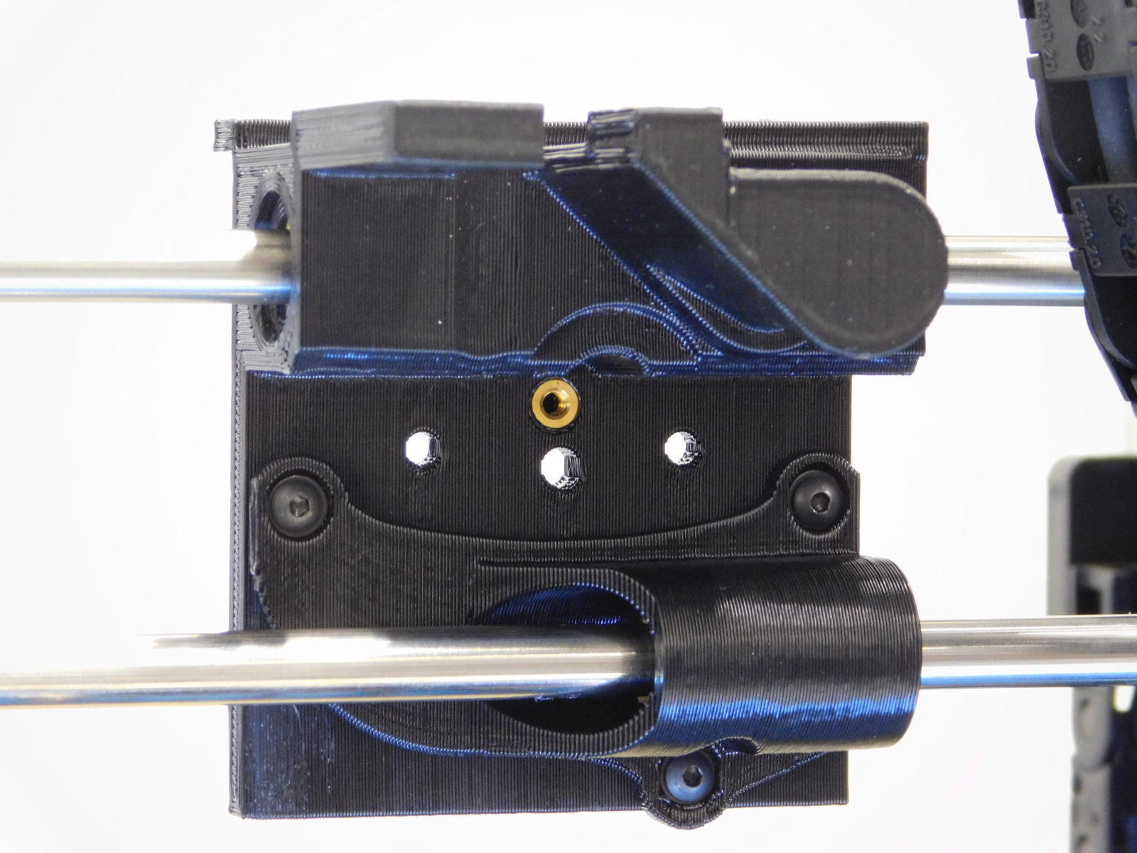
Re-install all four of the M3x8 BHCS with washers [HD-BT0137] & [HD-WA0038]
Torque all of these fasteners to 3in*lbs
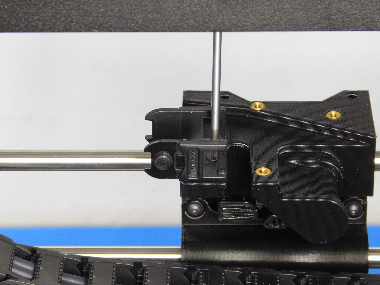
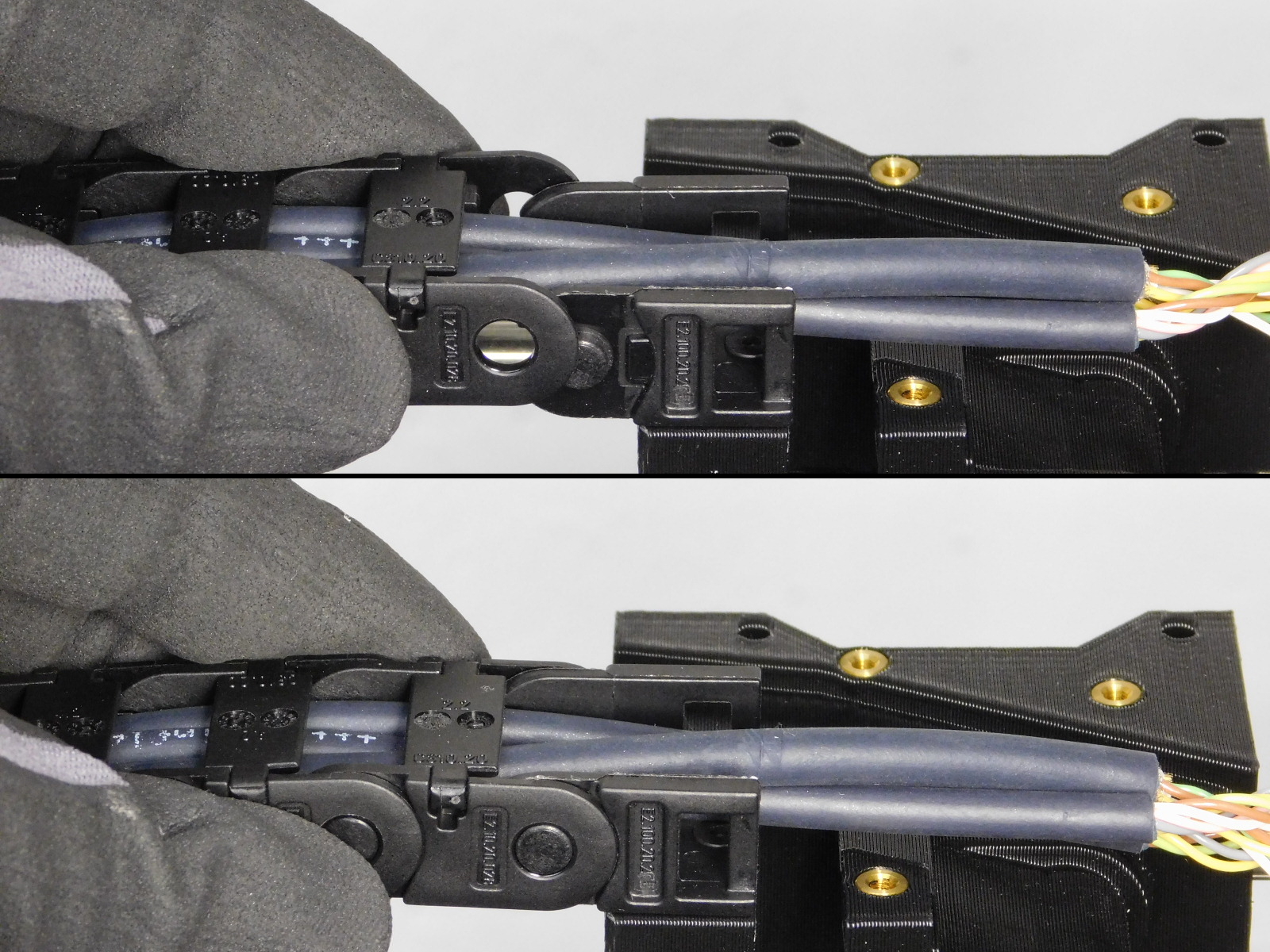
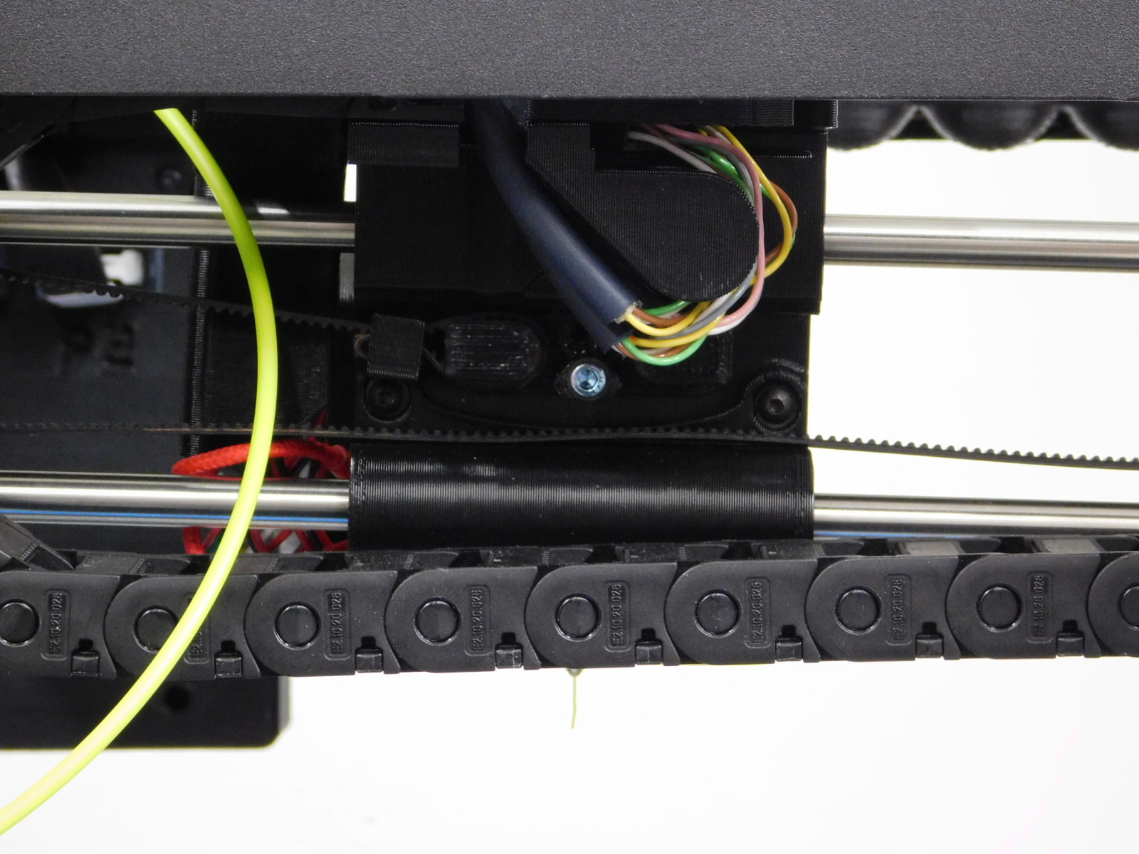
Remove the zip tie from the end of the cable chain.
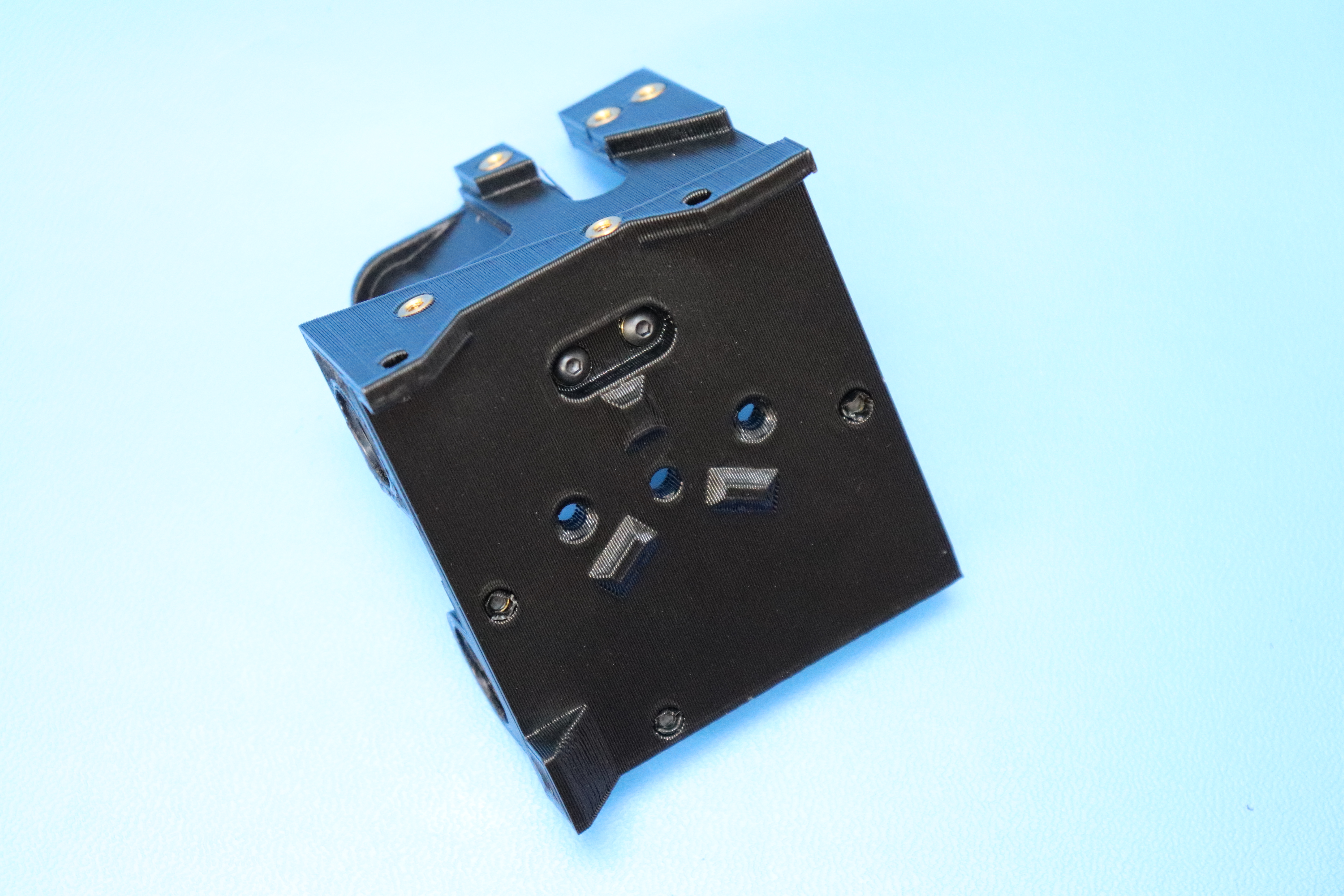
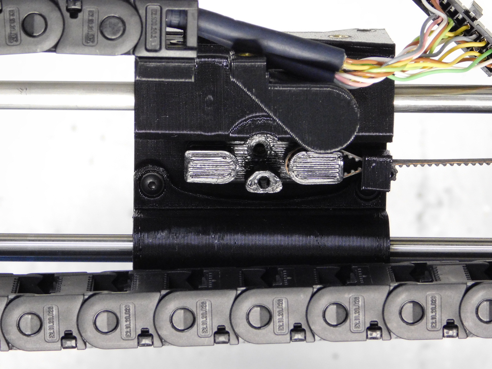
Remove the cable chain mount from the cable chain and attach to the X-Carriage as pictured using two M3x6 FHCS [HD-BT0128]
Re-attach the cable chain to the mount as pictured.

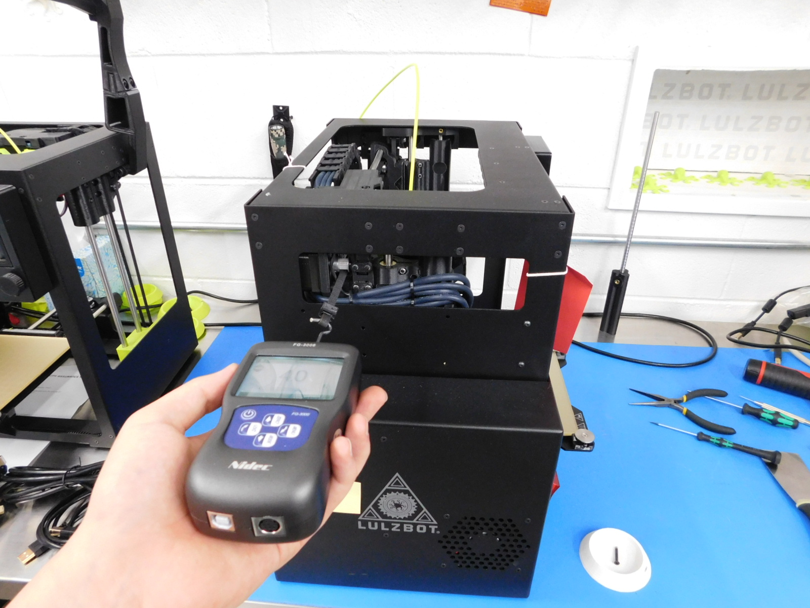
Using the force gauge, measure the carriage drag as shown. If the drag is above 15N, check the individual bushing drags. If needed, carefully broach the bushing set to reduce the drag with the special broaching tool for a maximum of one pass.
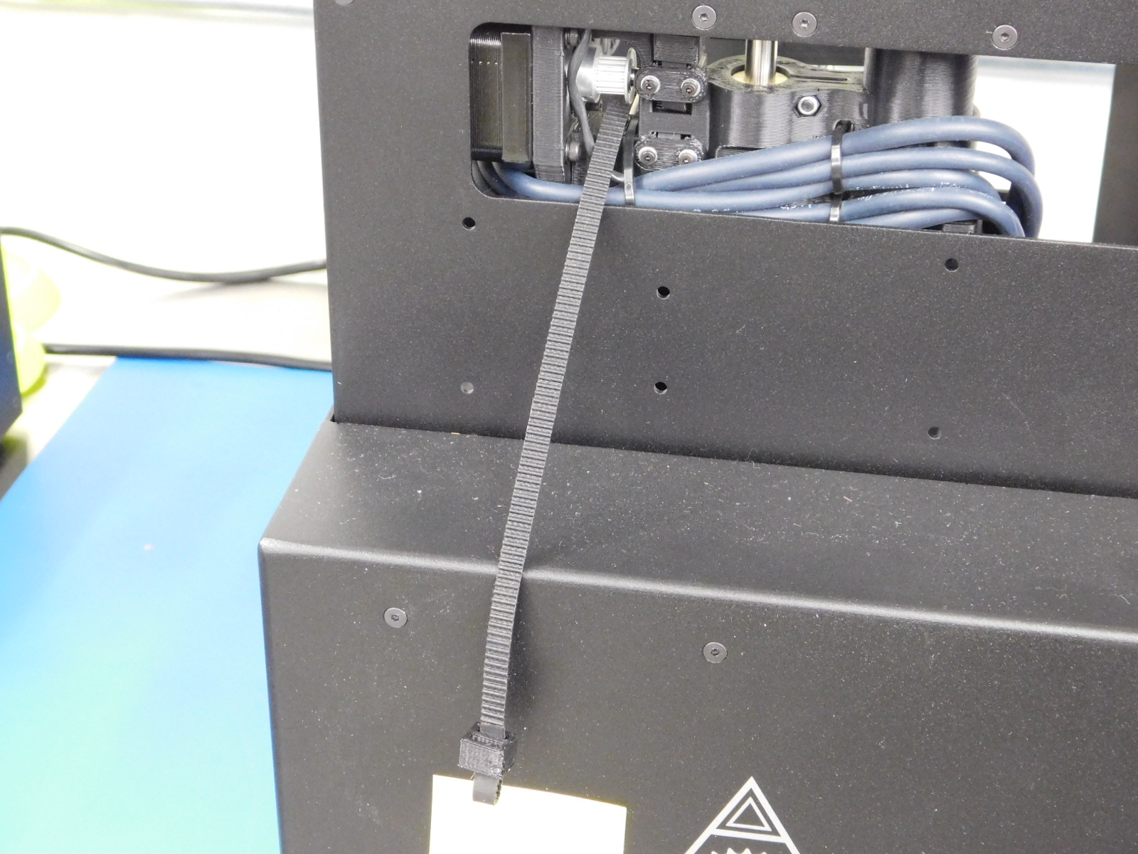
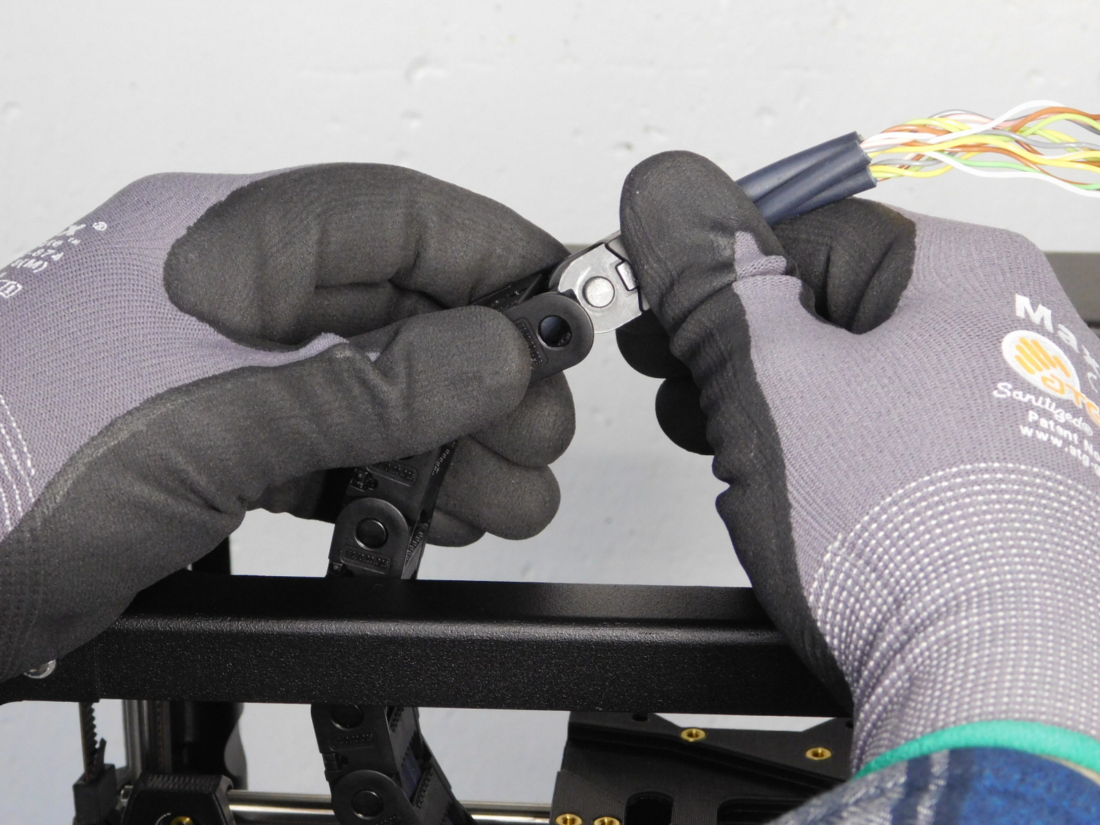
Cut a Timing Belt [HD-BL0033] straight with the teeth of the belt to make an open belt
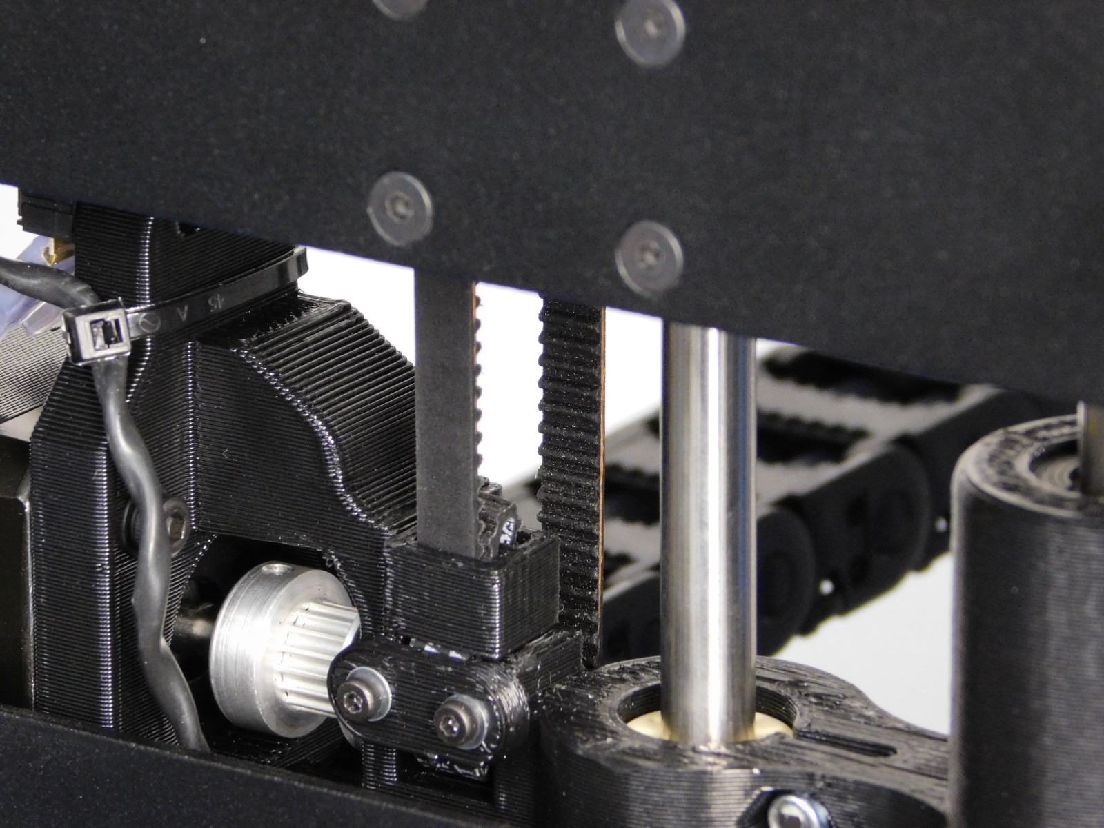
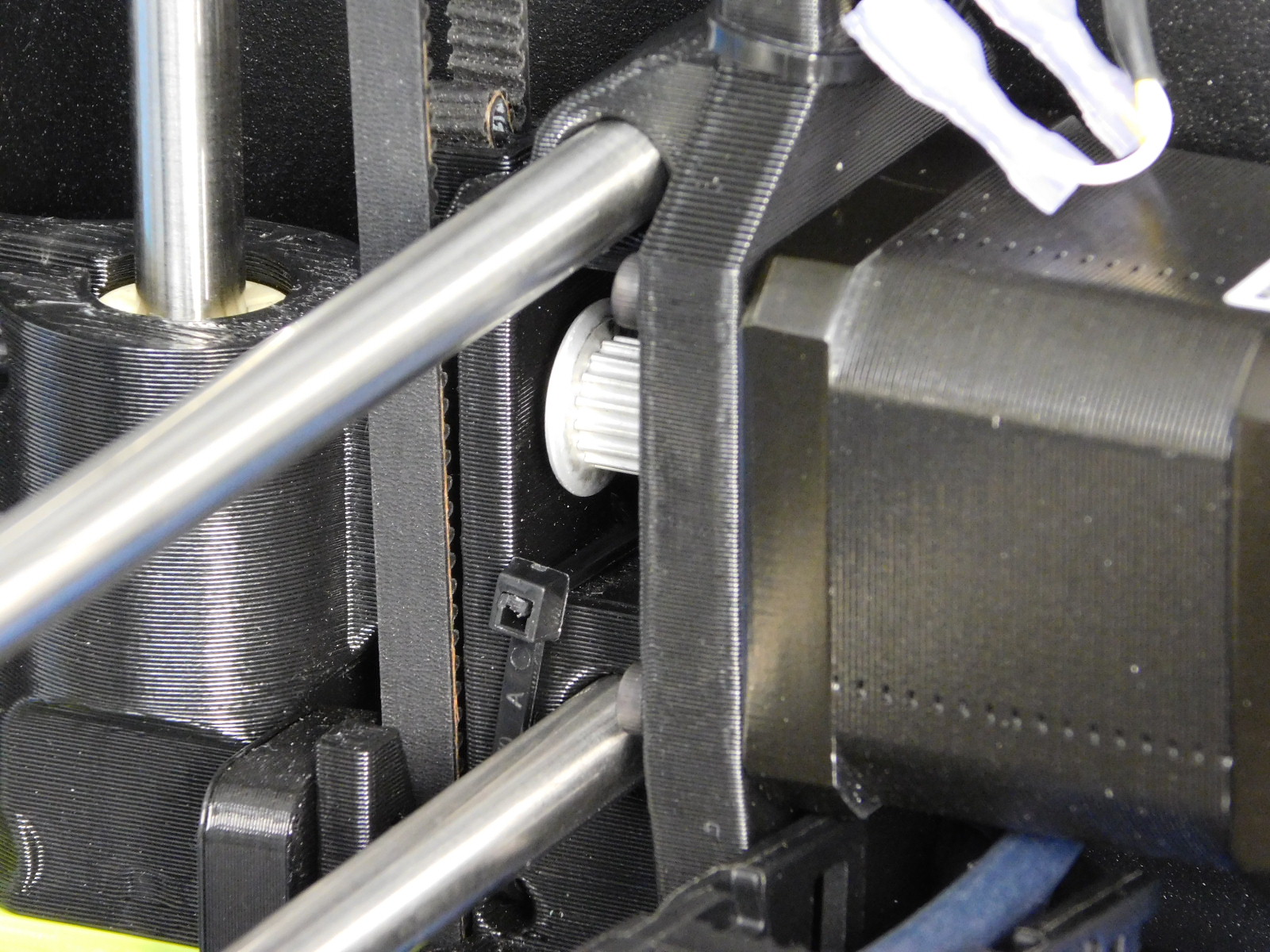
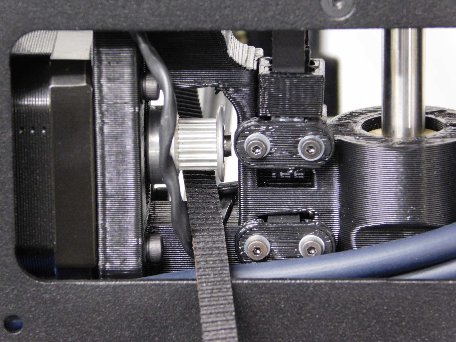
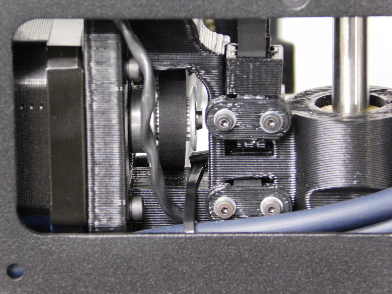
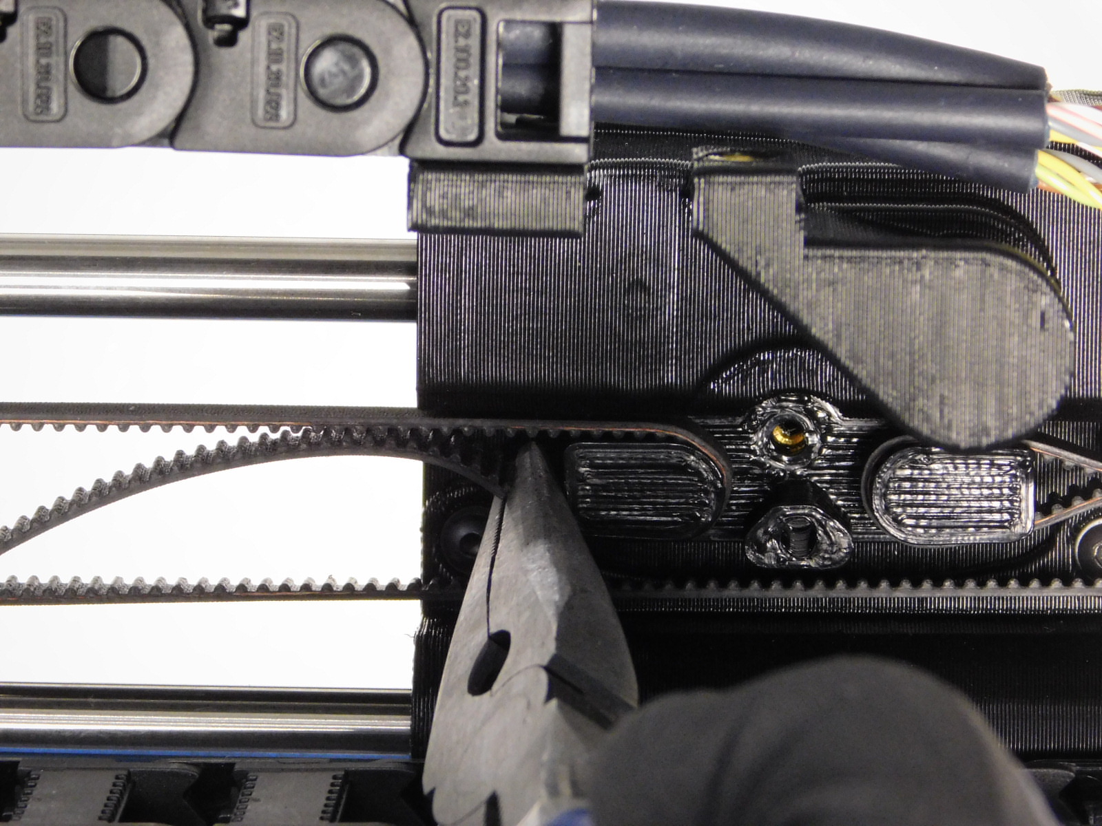
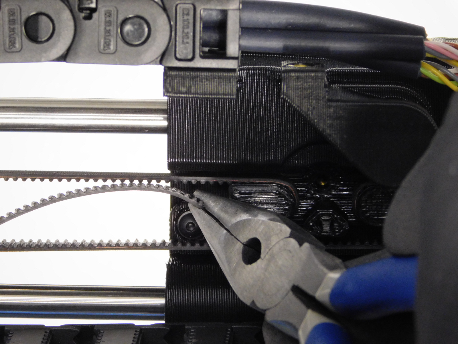
Grabbing the bottom of the X-Axis, lift the Z-Axis so that the X-Motor pulley can be seen through the cut-out in the left frame plate.
Beginning from the left with the teeth of the belt facing up, feed the drive belt underneath the X-Motor pulley.
Continue back over the X-Motor pulley, back through the X-End Motor printed part.
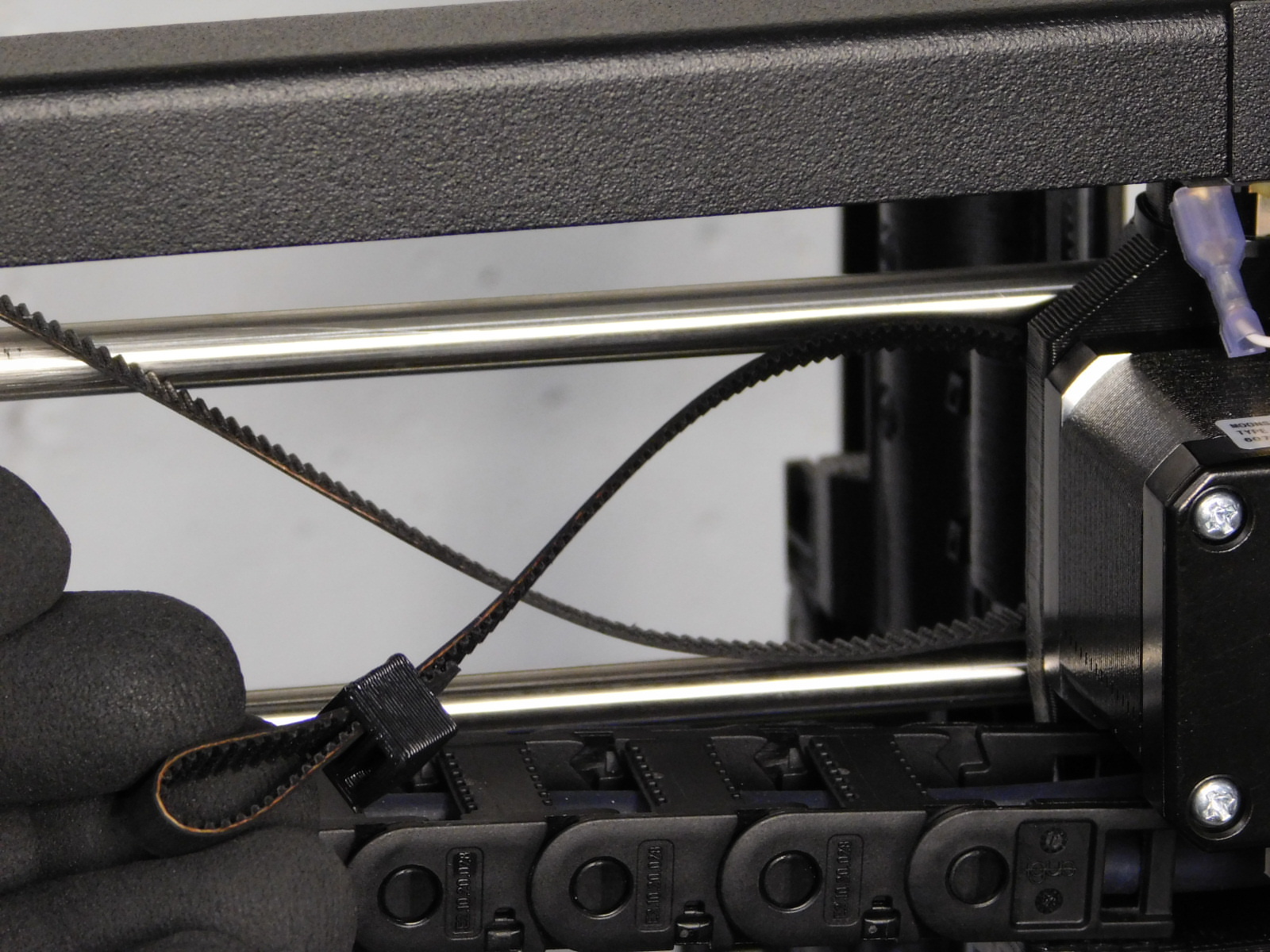
Slide one Belt Tensioning Collar [PP-GP0307] onto the end of the belt with the narrow end facing the X-End Motor, and the second slack retaining slot facing down.
Fold the belt 40mm from the end so that the teeth of the belt are together.
Slide the Belt Tensioning Collar [PP-GP0307] down over both belt halves, forming a loop at the end.
(both ends of belt will pass through the larger slot of the collar)
It is often helpful to grip the end of the belt at the narrow end of the tensioning collar just after the end is through to slide the Belt Tensioning Collar on further.
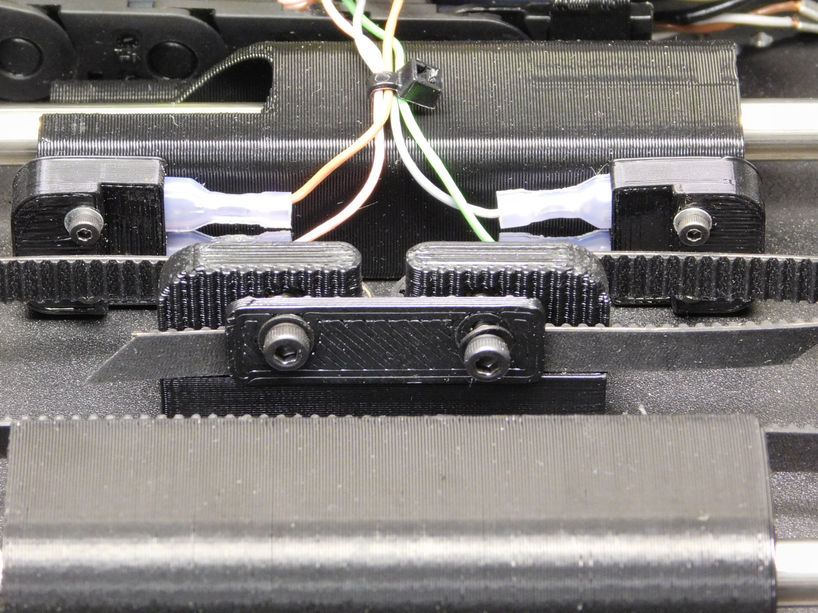
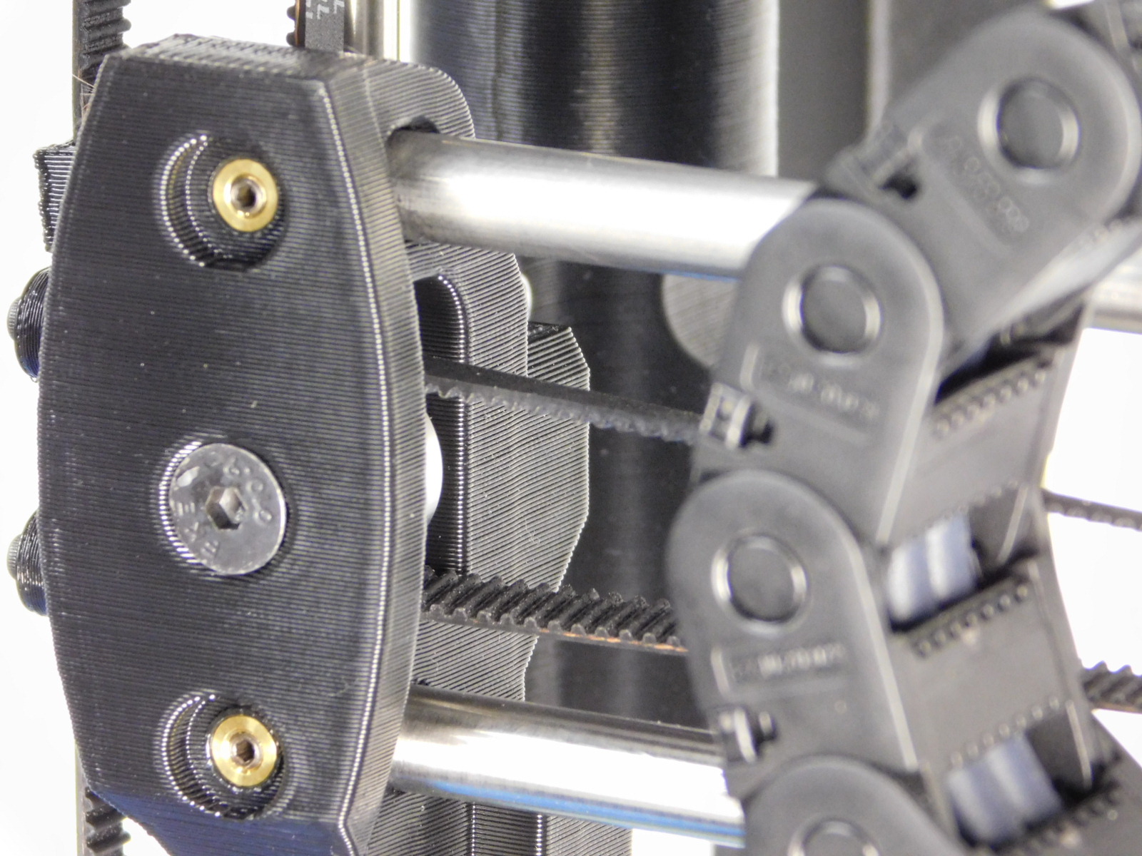
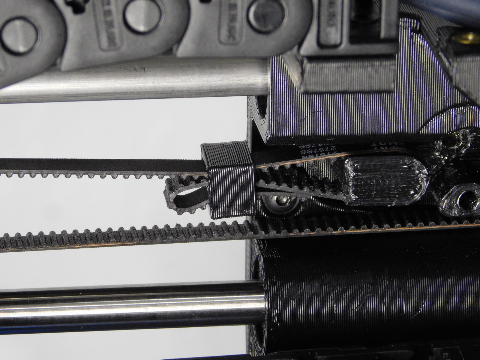
Slide the looped end of the belt over the X-Belt Mount post on your right (X-End Motor side)
Slide the Belt Tensioning Collar [PP-GP0307] so that its left edge is 10mm from the right edge of the X-Belt Mount post.
Tuck the belt slack into the second slot on the collar.
With the other end of the belt, begin by passing the belt to your left, underneath the X-End Idler bearings; teeth facing up.
Continue up and around the X-Idler bearings, passing back through the X-End Idler printed part above the bearings.
Make sure there are no twists in the belt.
Slide one Belt Tensioning Collar [PP-GP0307] onto the end of the belt with the narrow end facing the X-End Idler.
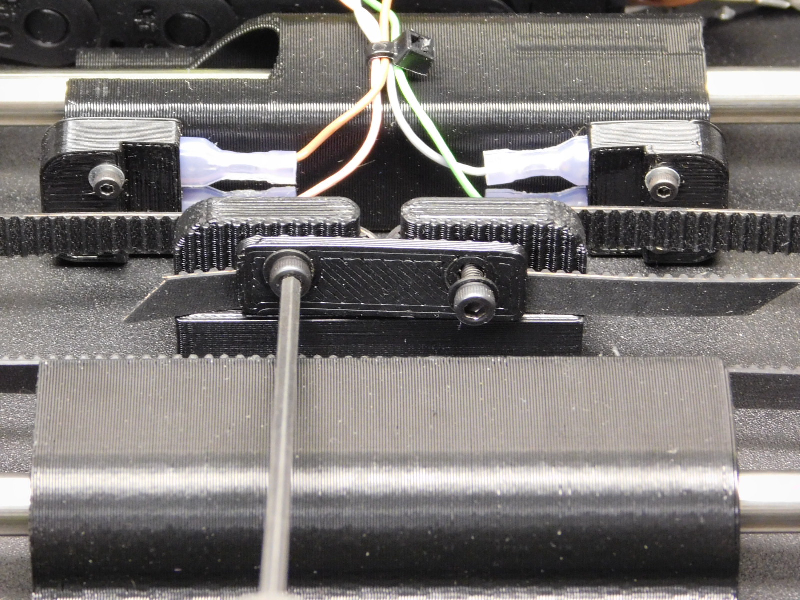
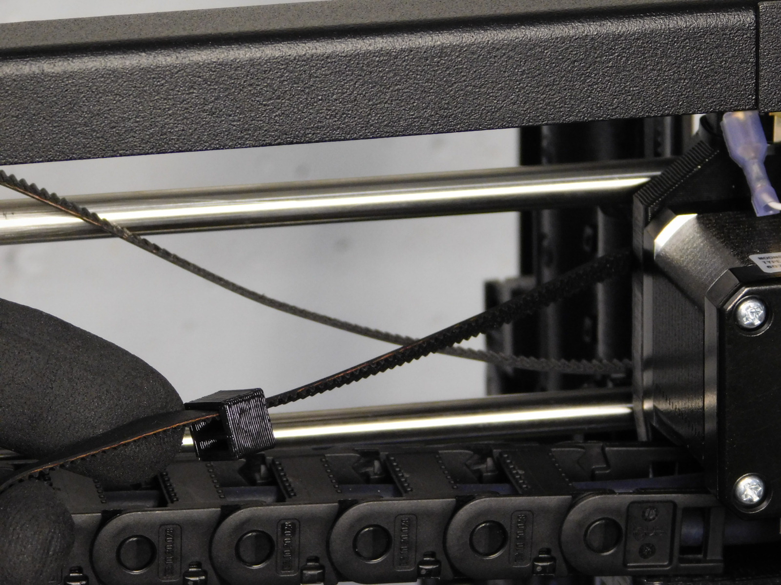
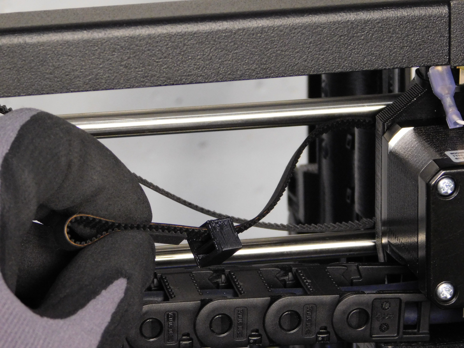
Fold the belt down and around the X-Belt Mount post on your left (X-End Idler side) and pulling to your left make a loop.
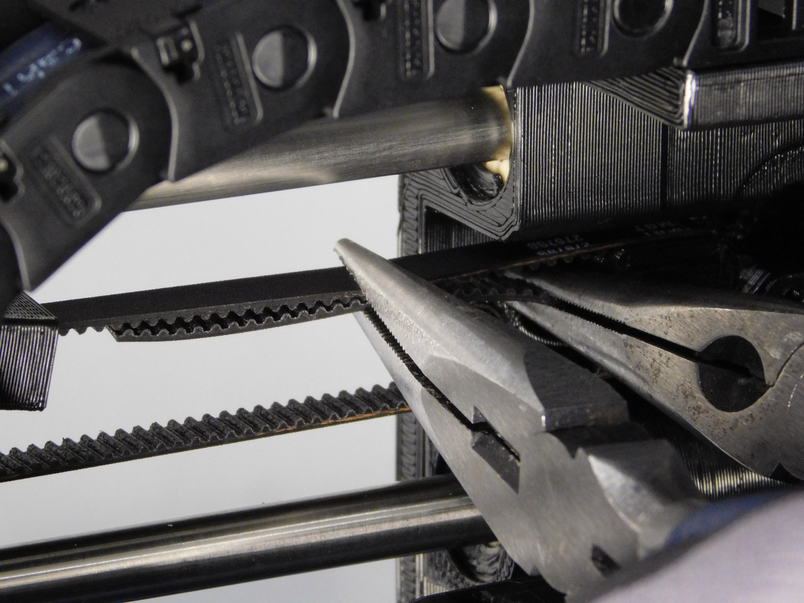
Grab the bottom side of the belt just to the left of the X-Belt Mount post and leverage your hand to the right to tension the belt.
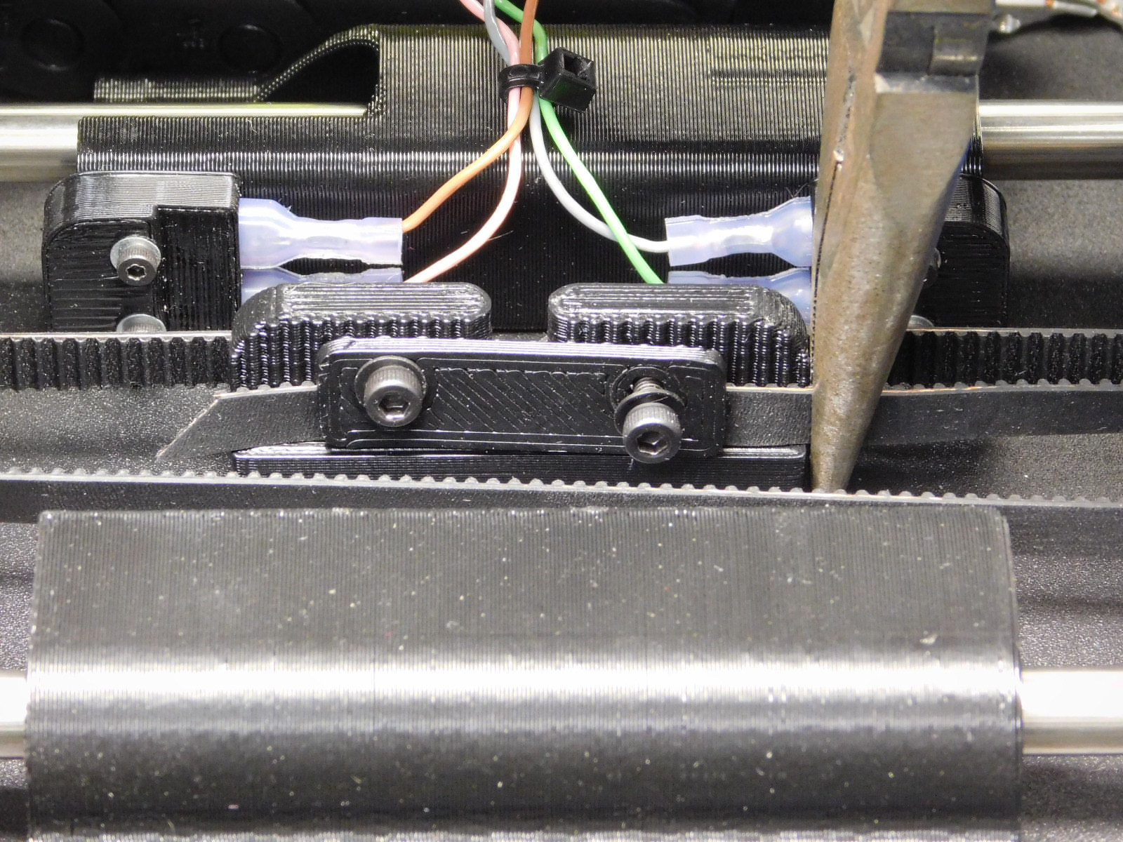
With another pair of pliers, grip both halves of the belt just to the left of the pliers in your right hand.
Slide the Belt Tensioning Collar [PP-GP0307] over the end of the belt, towards the X-Carriage.
It is often helpful to grip the end of the belt at the narrow end of the tensioning collar just after the end is through to slide the Belt Tensioning Collar on further.
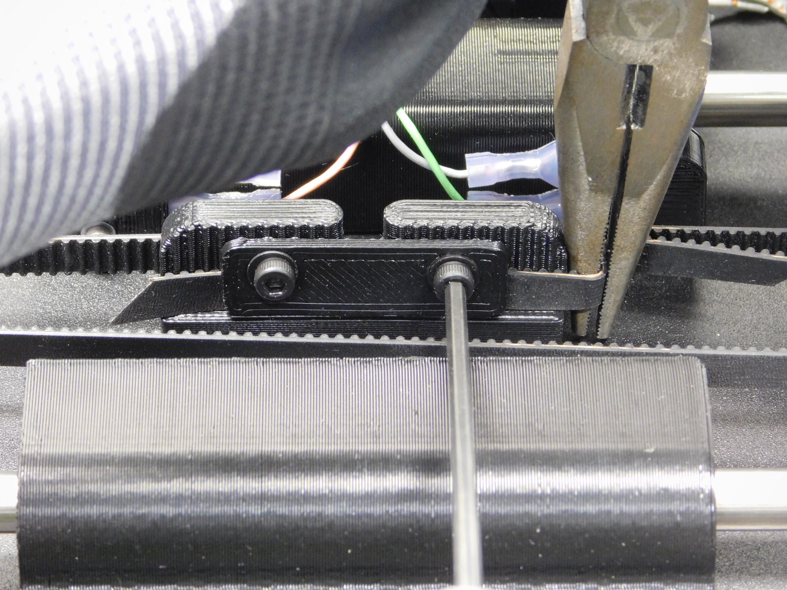
Slide the Belt Tensioning Collar [PP-GP0307] until its right edge is 10mm from the left edge of the X-Belt Mount post.
Trim excess belt to the left of the tensioning collar straight with the teeth of the belt, leaving ~15mm of excess.
Use setting number 2 on the 508C Sonic Tension Meter to ensure the belt is tensioned sufficiently.
Acceptable tension for the X-Belt is 23-40N, refer to the 508C Sonic Tension Meter OHAI-kit. It is best to set the belt towards the top of the range, because they will settle to a lower tension after burn-in.
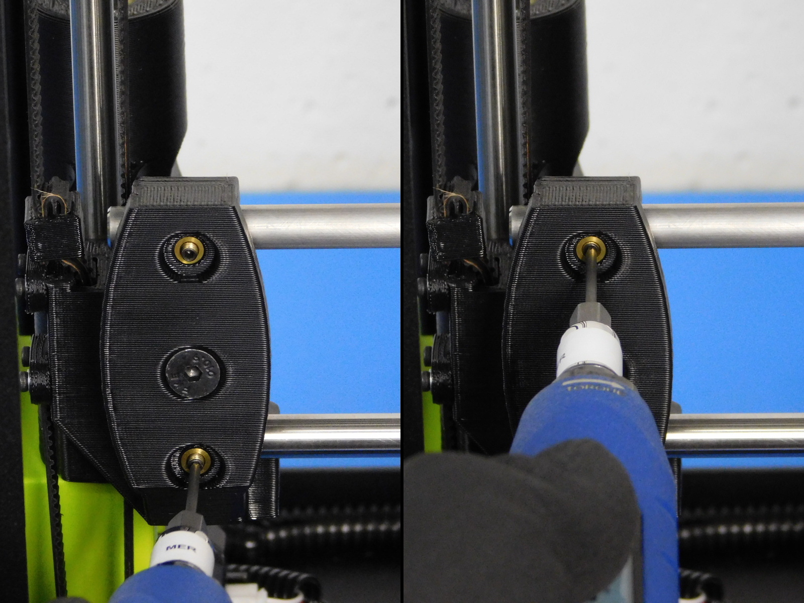
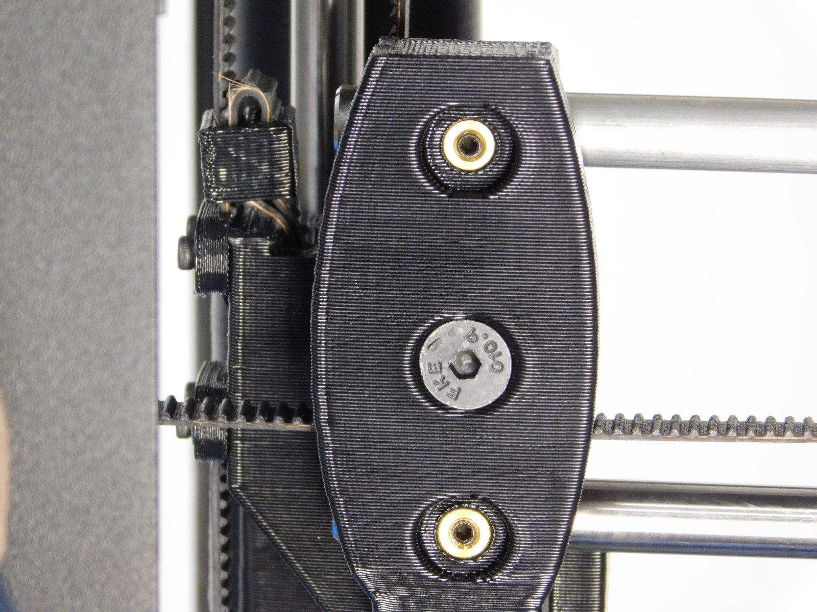
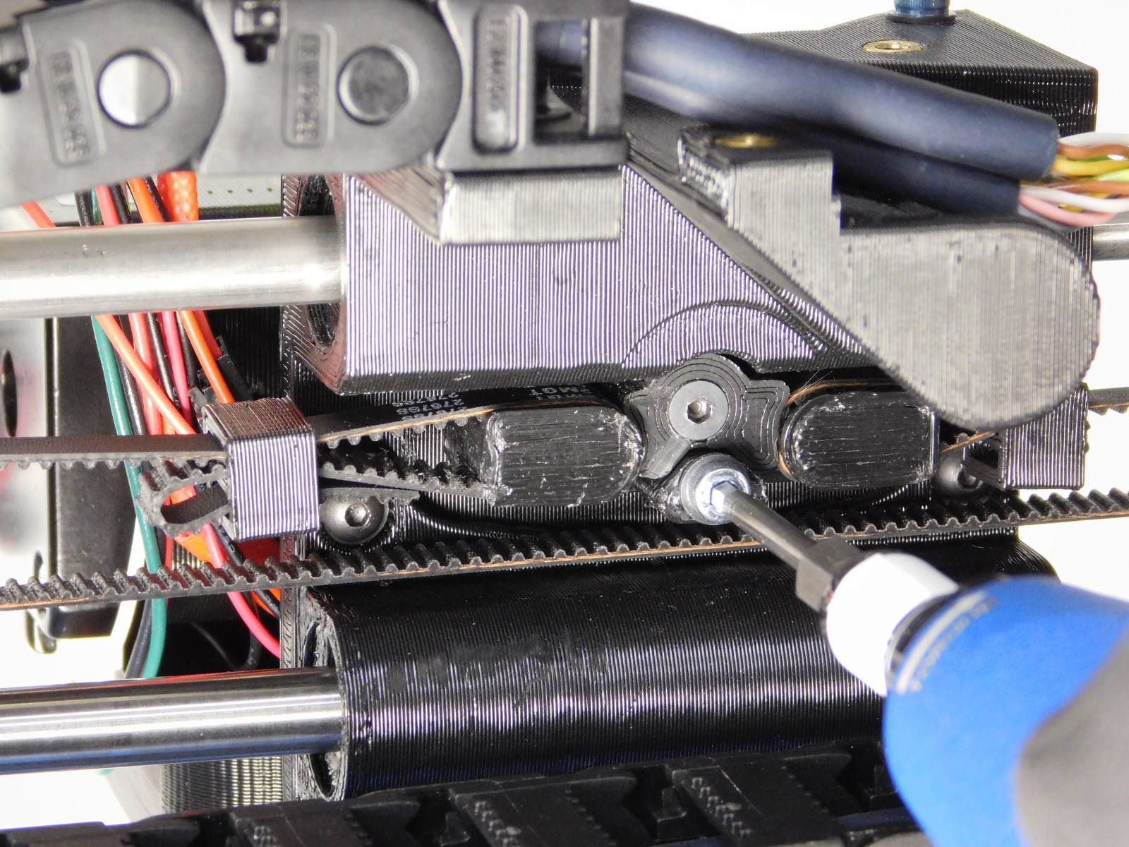
Install the X-Belt Tensioner Post [PP-GP0333] between the posts of the X-Belt Mount, oriented as pictured, using one M3x22 FHCS [HD-BT0204]
Torque to 3in*lbs

Line up the extruder [AS-TH0066] with the X-Carriage
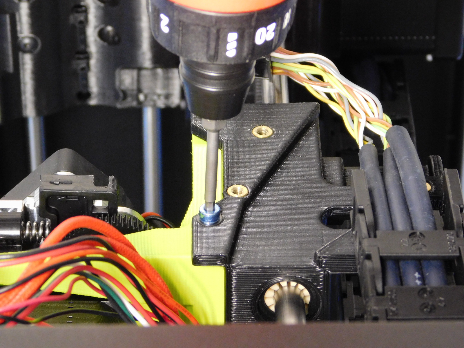
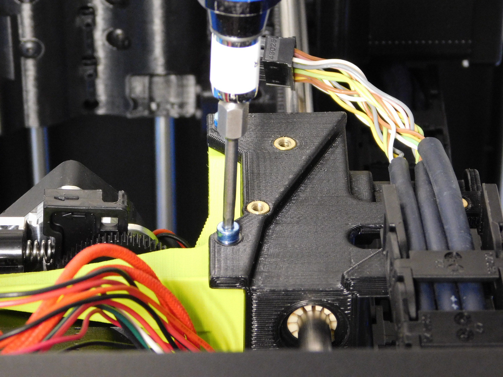
First secure from the back using one M3x30 Blue SHCS with washer [HD-WA0038] through the lower open hole in the X-Belt Mount.
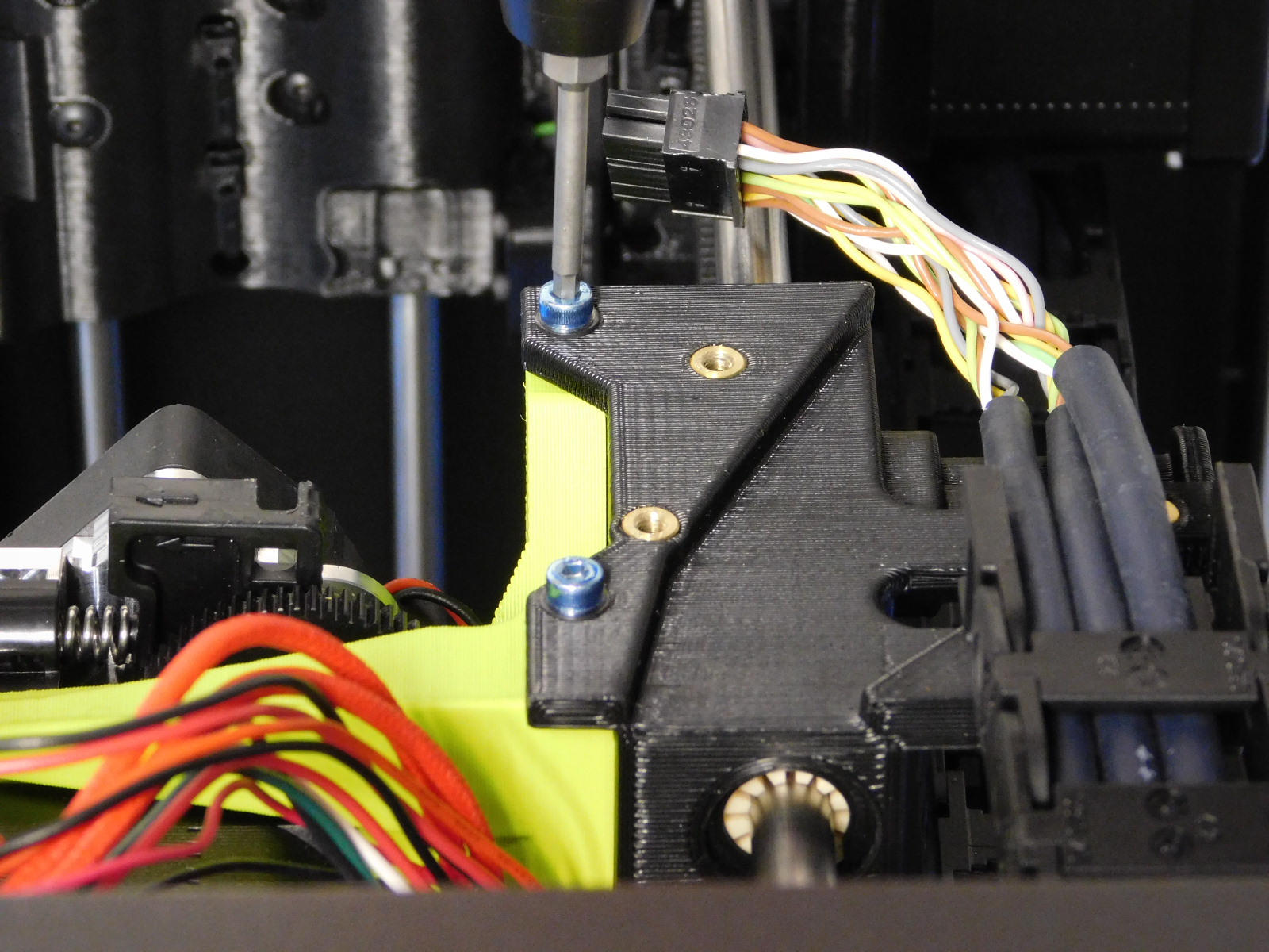
Then secure from above using two M3x8 Blue SHCS [HD-BT0211] with washers [HD-WA0038]
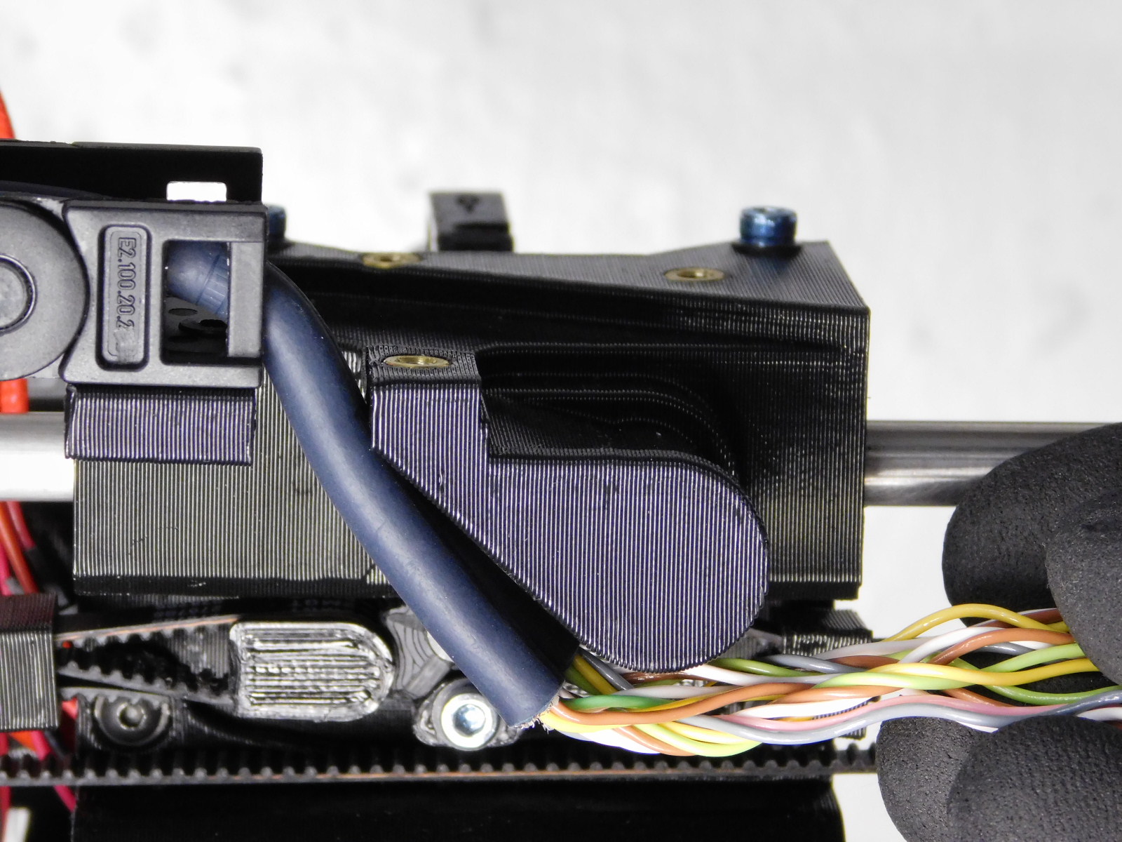
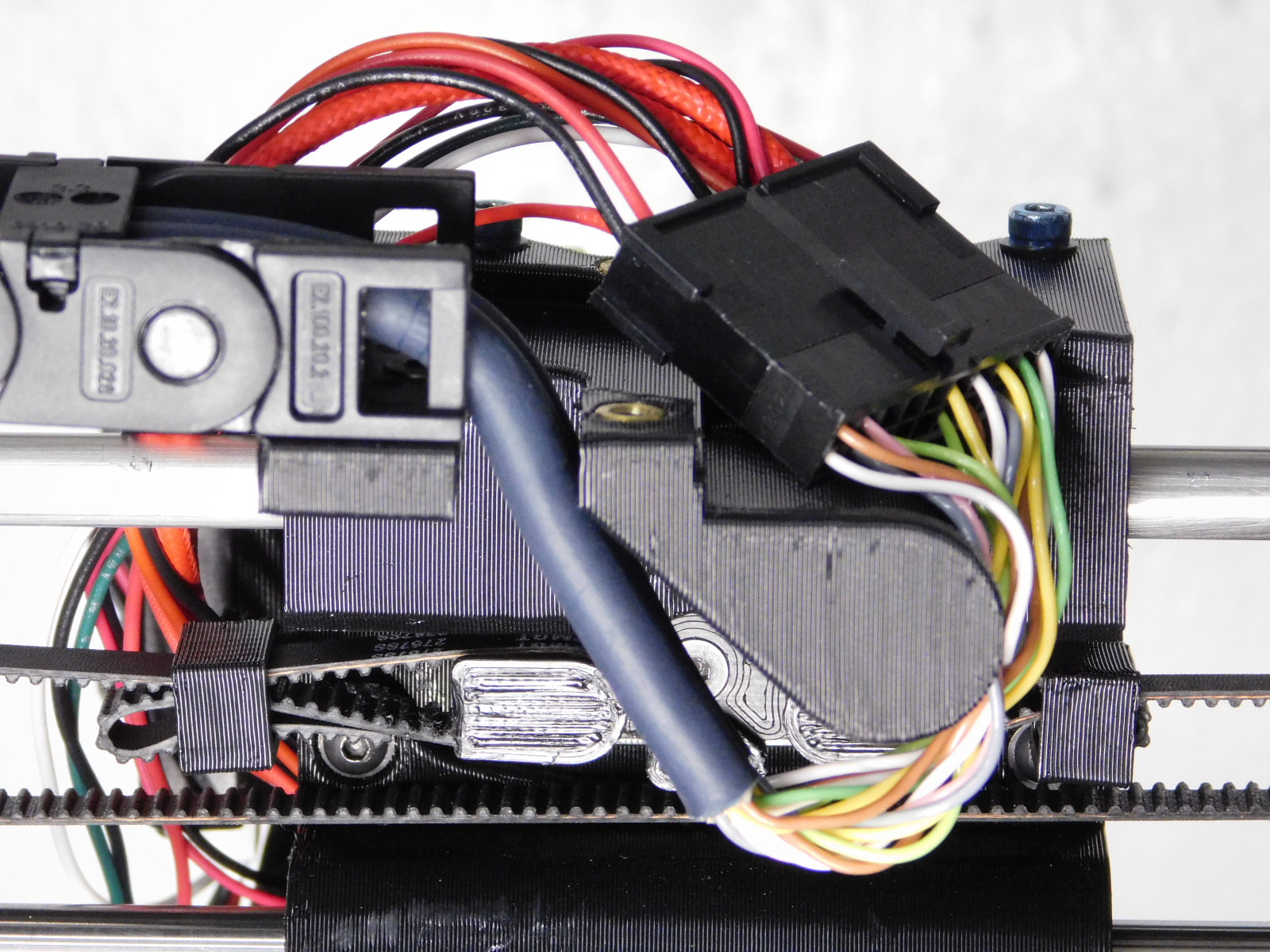
Connect the extruder to the extruder harness as pictured; first routing the cables down through the slot in the top of the X-Carriage before wrapping around and back up to meet connectors.
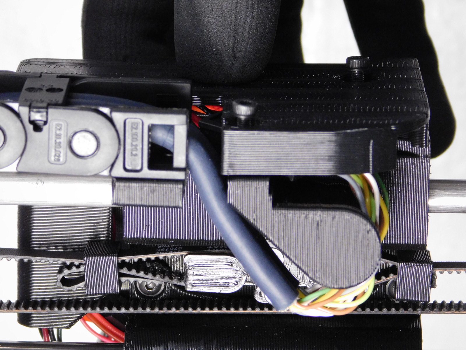
Slide the cable pathway of the X-Carriage Cap [PP-GP0320] over the exposed wiring of the toolhead and make sure it rests atop the X-Carriage without pinching any wires.
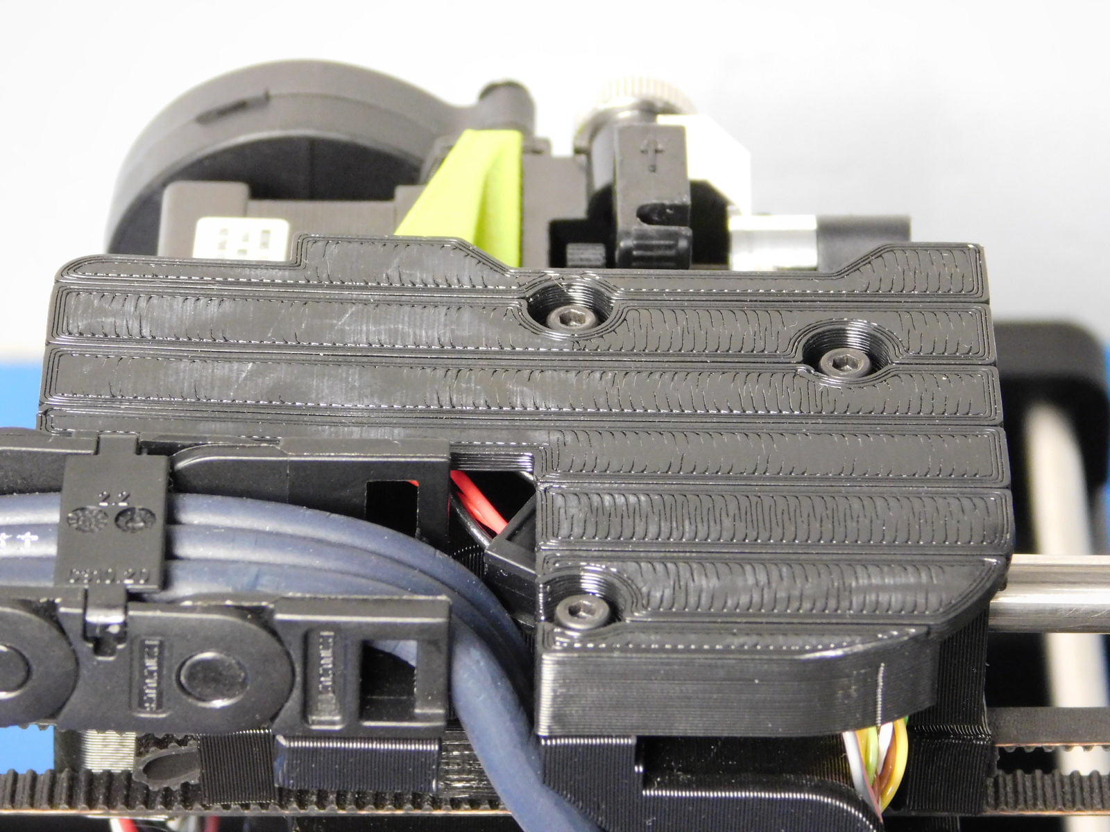
Secure the X-Carriage Cap [PP-GP0320] using 3x M3x12 SHCS [HD-BT0039] with washers [HD-WA0038]
Torque until the screw heads are flush with the top of the X-Carriage Cap.

Install the Spool Arm Assembly [AS-PR0107] to the four open holes in the top of the right frame plate using 4x M3x6 FHCS [HD-BT0128]
Torque to 5in*lbs