Open HardwareAssembly Instructions
Guides for installation and assembly of the LulzBot line of products made by Aleph Objects, Inc.
Guides for installation and assembly of the LulzBot line of products made by Aleph Objects, Inc.
Materials Required:
1x- [PP-FP0055] Left Frame
2x- [HD-BT0128] M3x6 FHCS
2x- [HD-BT0137] M3x8 BHCS
1x- [HD-BT0146] M3x12 BHCS
3x- [HD-WA0038] M3 black oxide washers
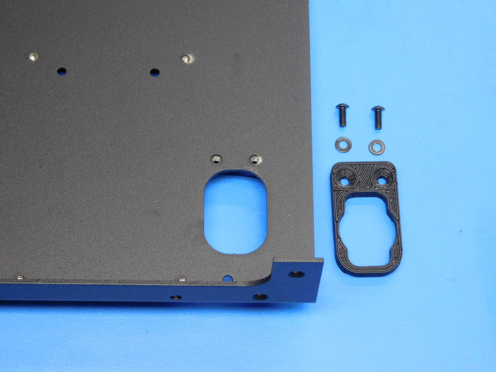
1x- [PP-IS0062] Upper Strain Relief Mount Assembly
1x- 30mm Cable chain mount end removed from EL-HR0130
Tools needed:
2mm hex driver
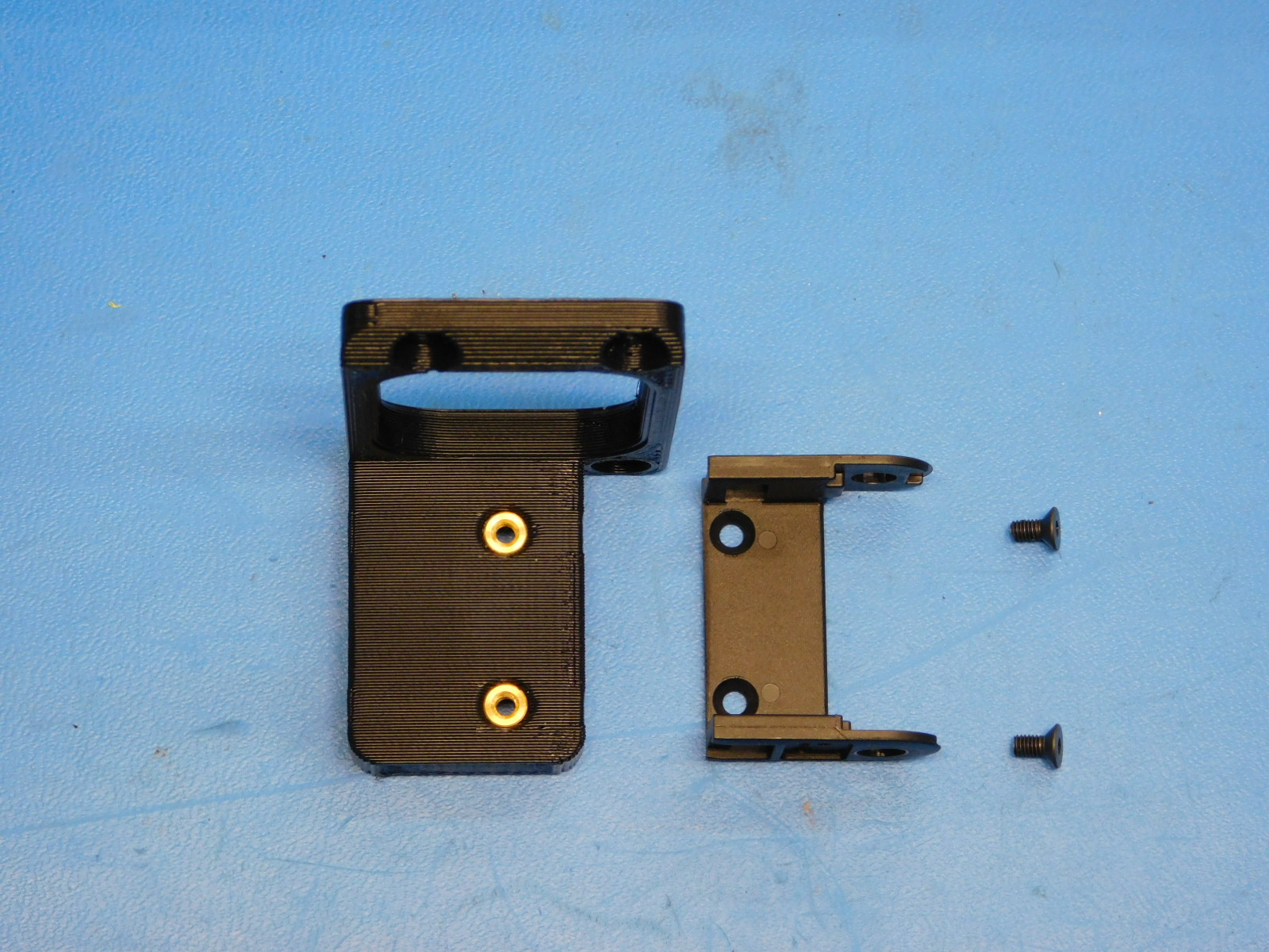
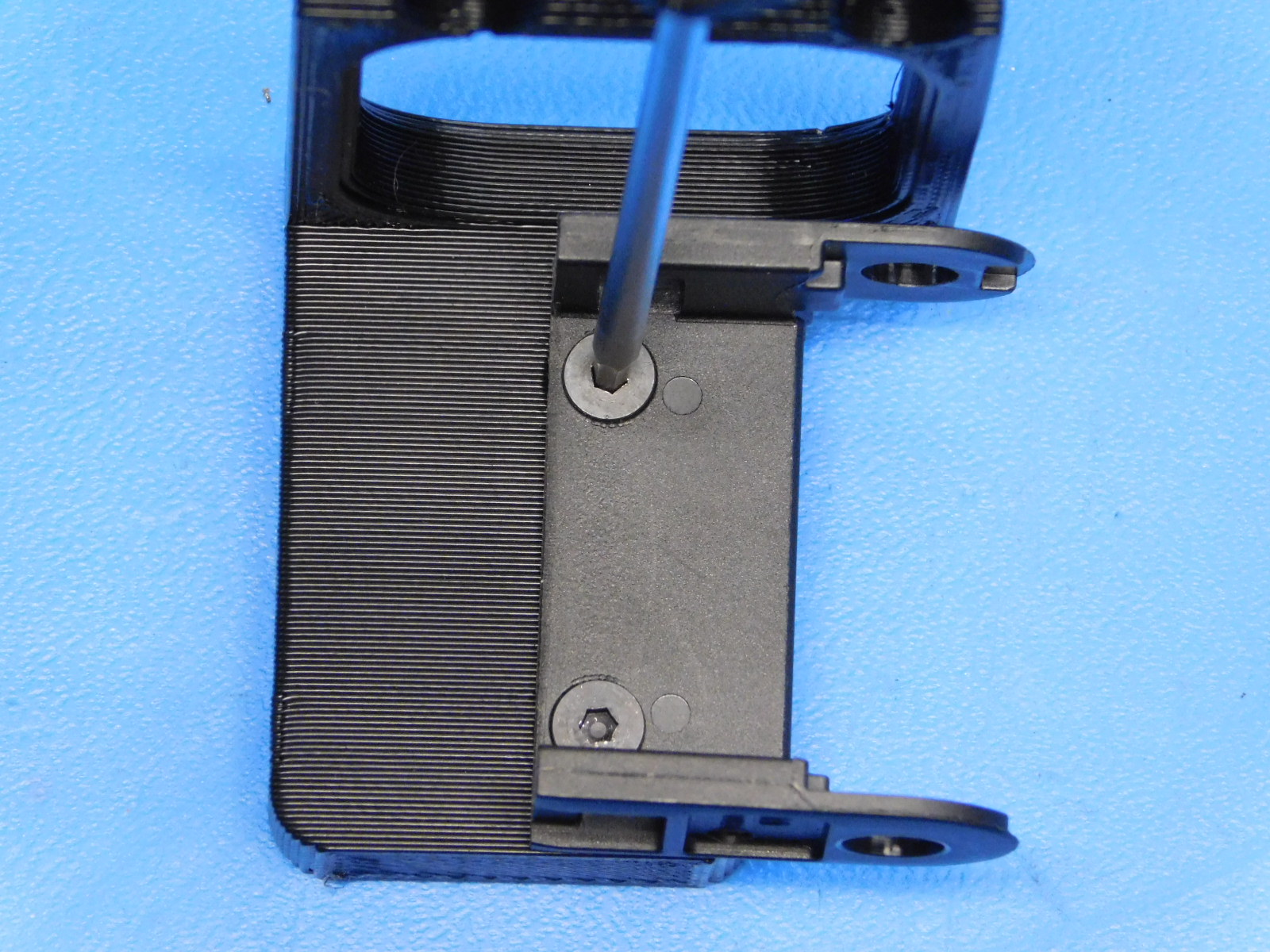
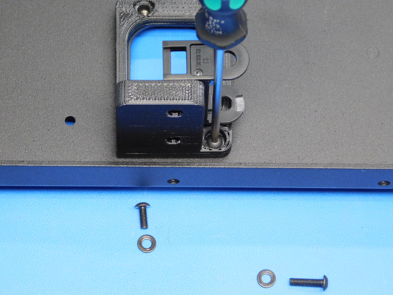
Using two M3x6 FHCS [HD-BT0128] secure the 30mm cable chain mount to the Upper Relief Mount Assembly [PP-IS0062]
Ensure the cable chain mount is oriented as pictured.
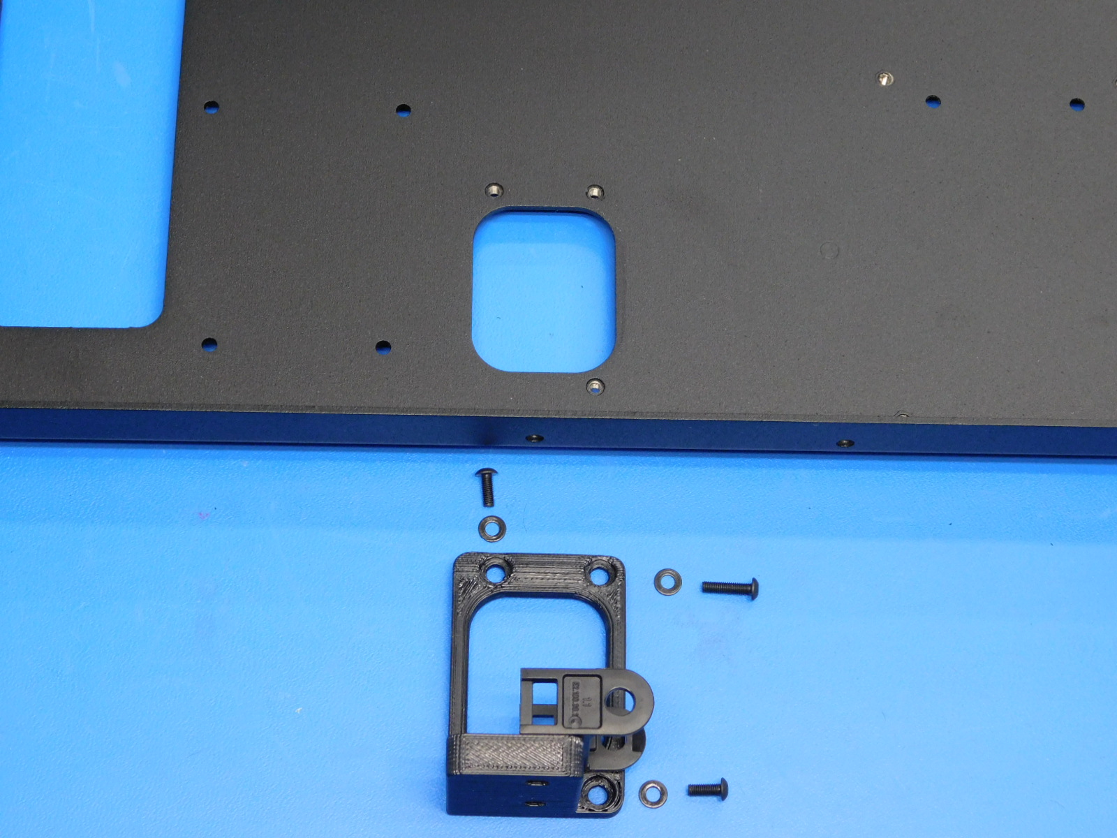
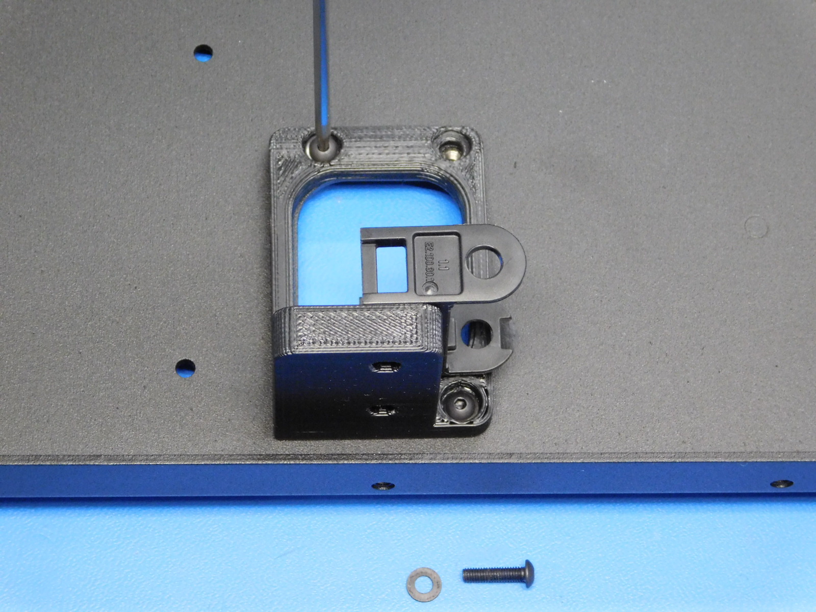
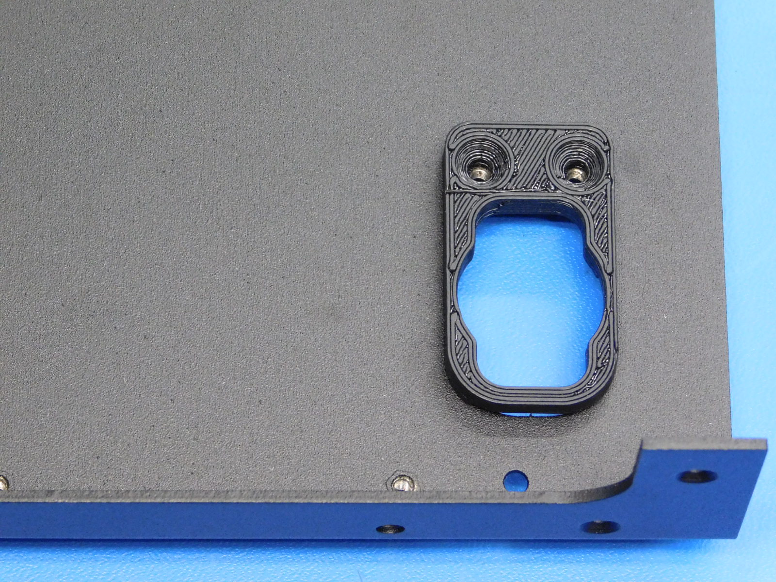
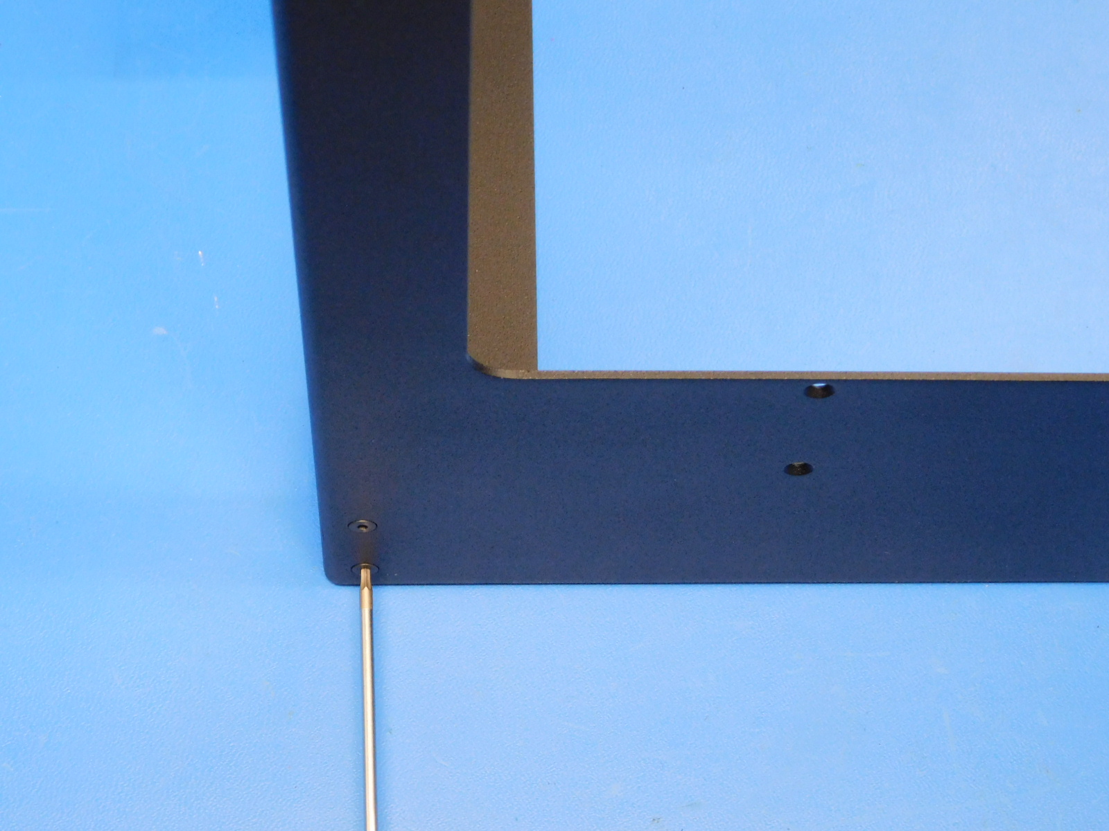
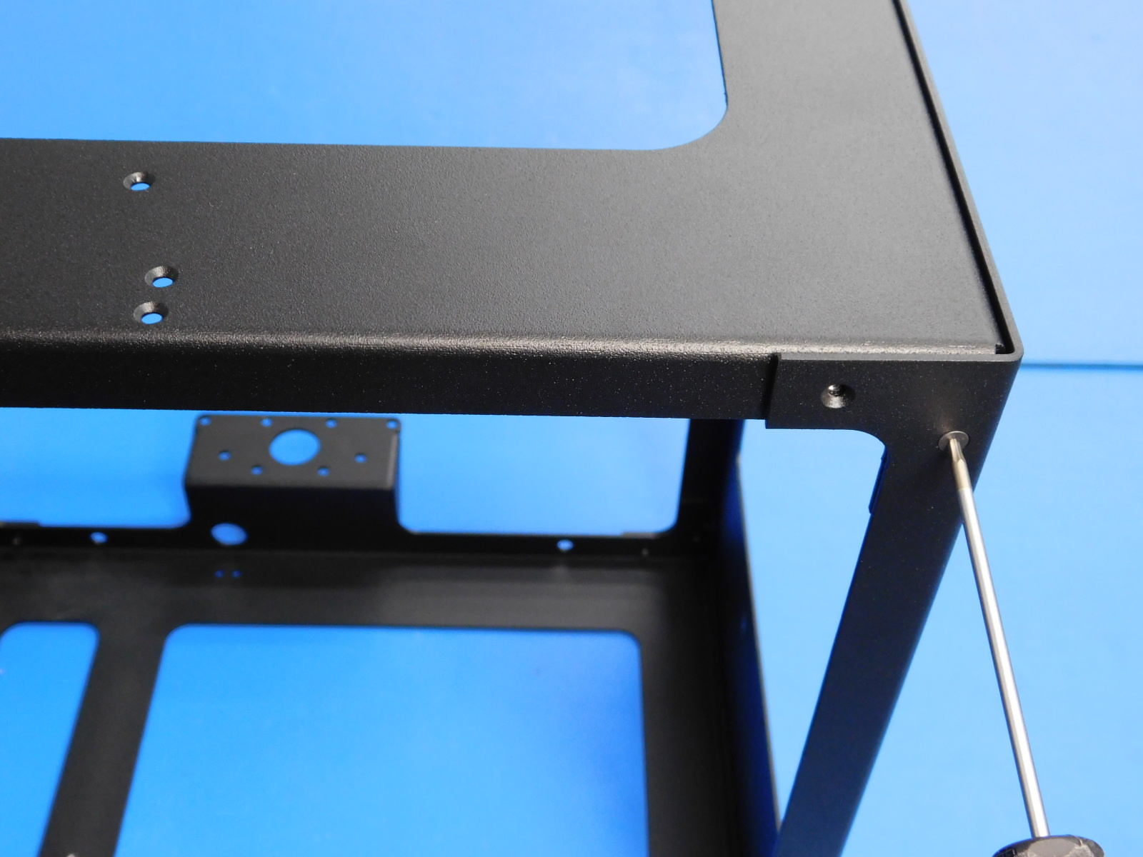
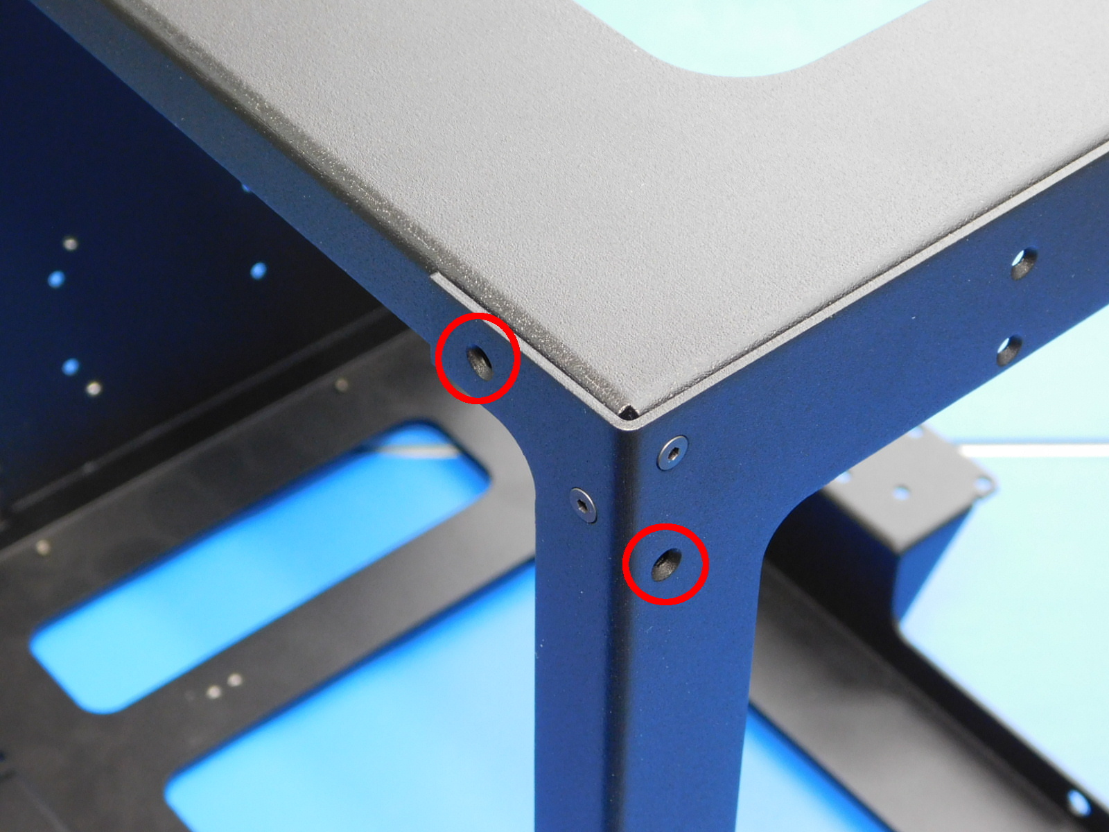
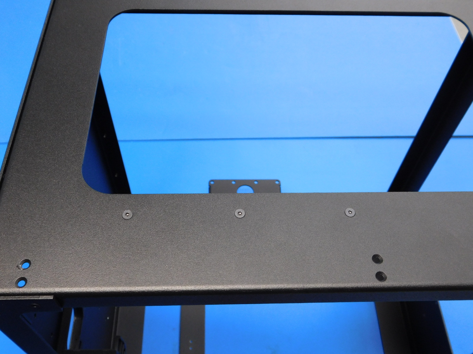
Align the upper strain relief holes with the three holes in the left frame.
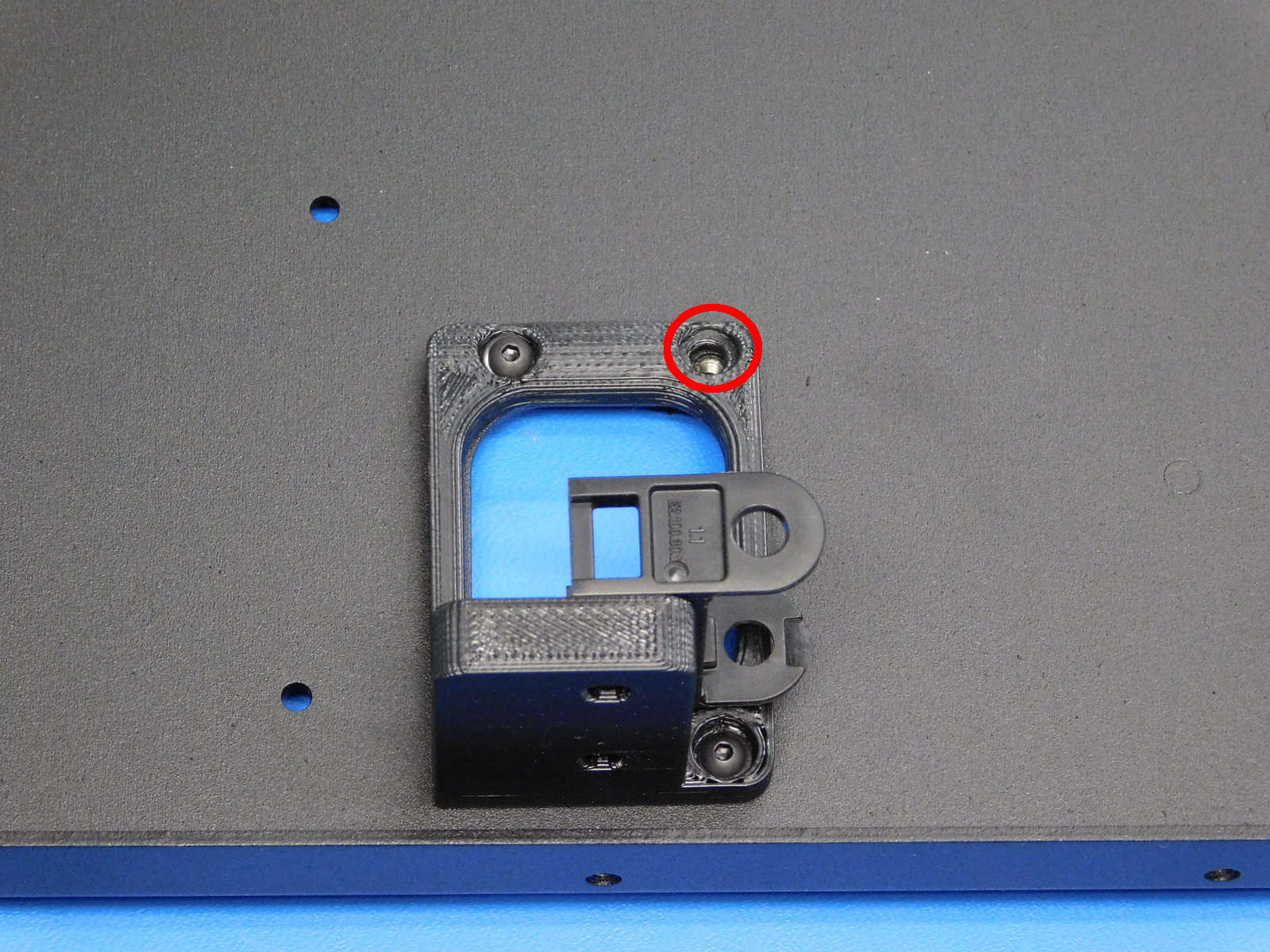
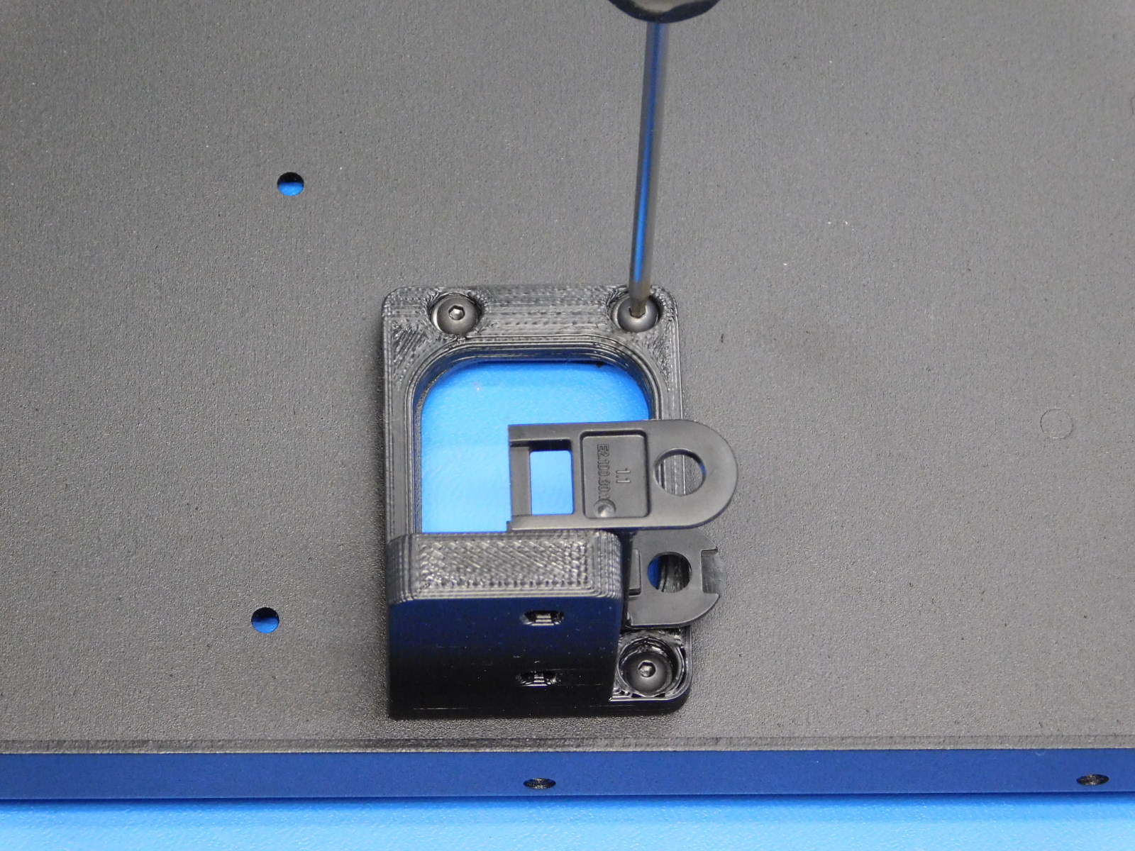
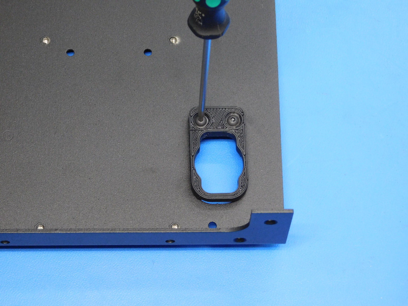
Secure the upper strain relief using two M3x8 BHCS [HD-BT0137] with washers [HD-WA0038] and one M3x12 BHCS [HD-BT0146] with washer [HD-WA0038] in the hole circled in red; see [reference#1].
Torque fasteners to 5in*lbs.
Materials Required:
1x- [PP-FP0055] Left frame
1x- [PP-GP0265] Lower strain relief
2x- [HD-BT0137] M3x8 BHCS
2x- [HD-WA0038] M3 black oxide washer
Tools needed:
2mm hex driver
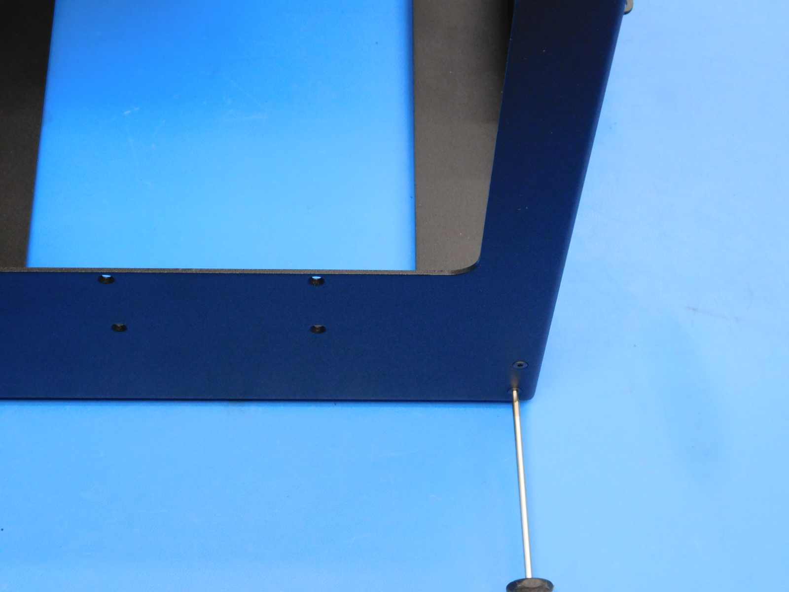
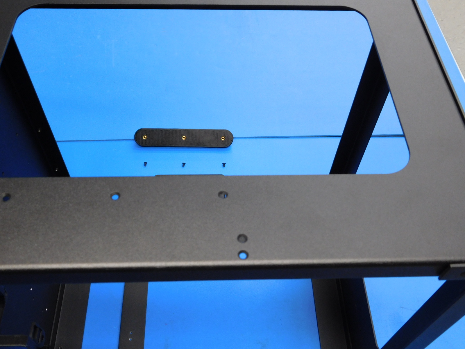
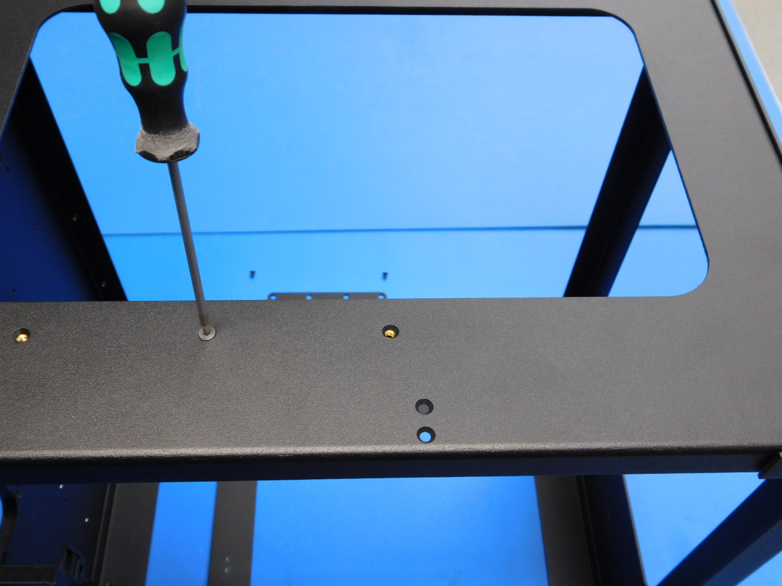
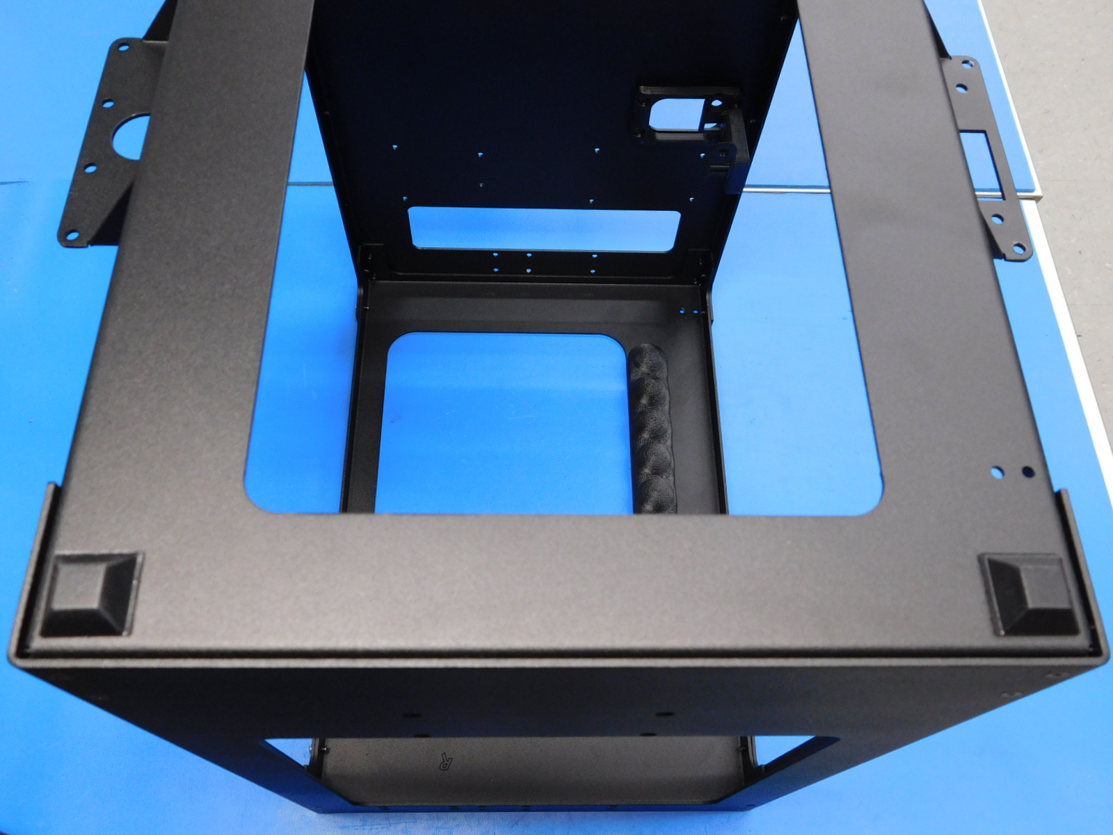
Align the lower strain relief with the holes on the left frame (see [reference#2] for mounting location and part orientation.)
Secure the lower strain relief with two M3x8 BHCS [HD-BT0137] with washers [HD-WA0038], torquing them to 5in*lbs.
Materials required:
1x- [PP-FP0055] Left frame plate
1x- [PP-MP0149] Bottom frame plate
7x- [HD-BT0128] M3x6 FHCS
1x- [HD-BT0104] M3x8 BHCS Stainless steel
1x- [HD-WA0035] External Tooth serrated lock washer
Tools needed:
2mm hex driver
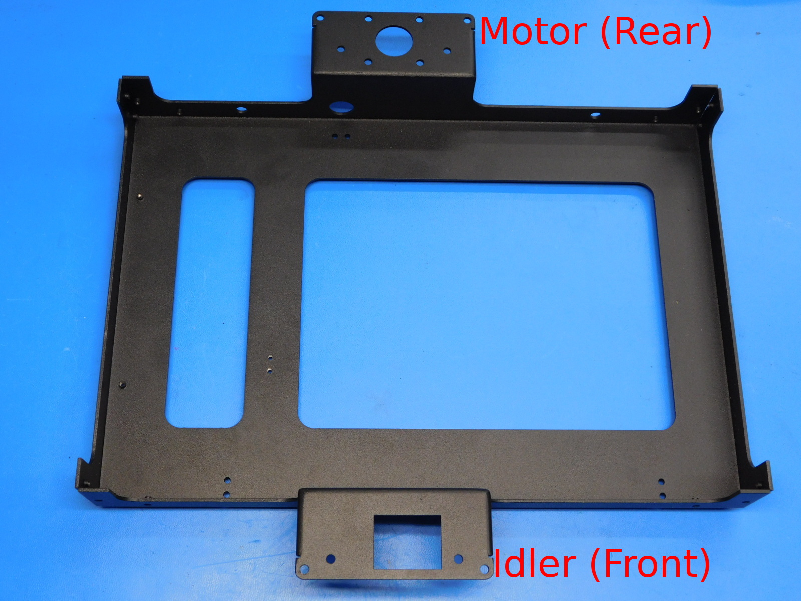
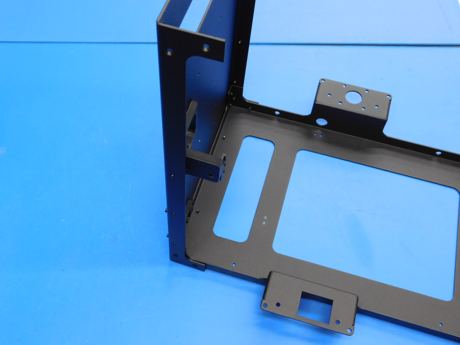
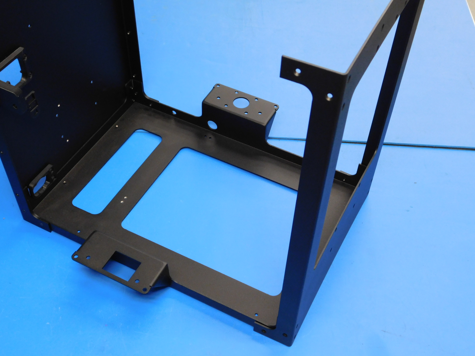
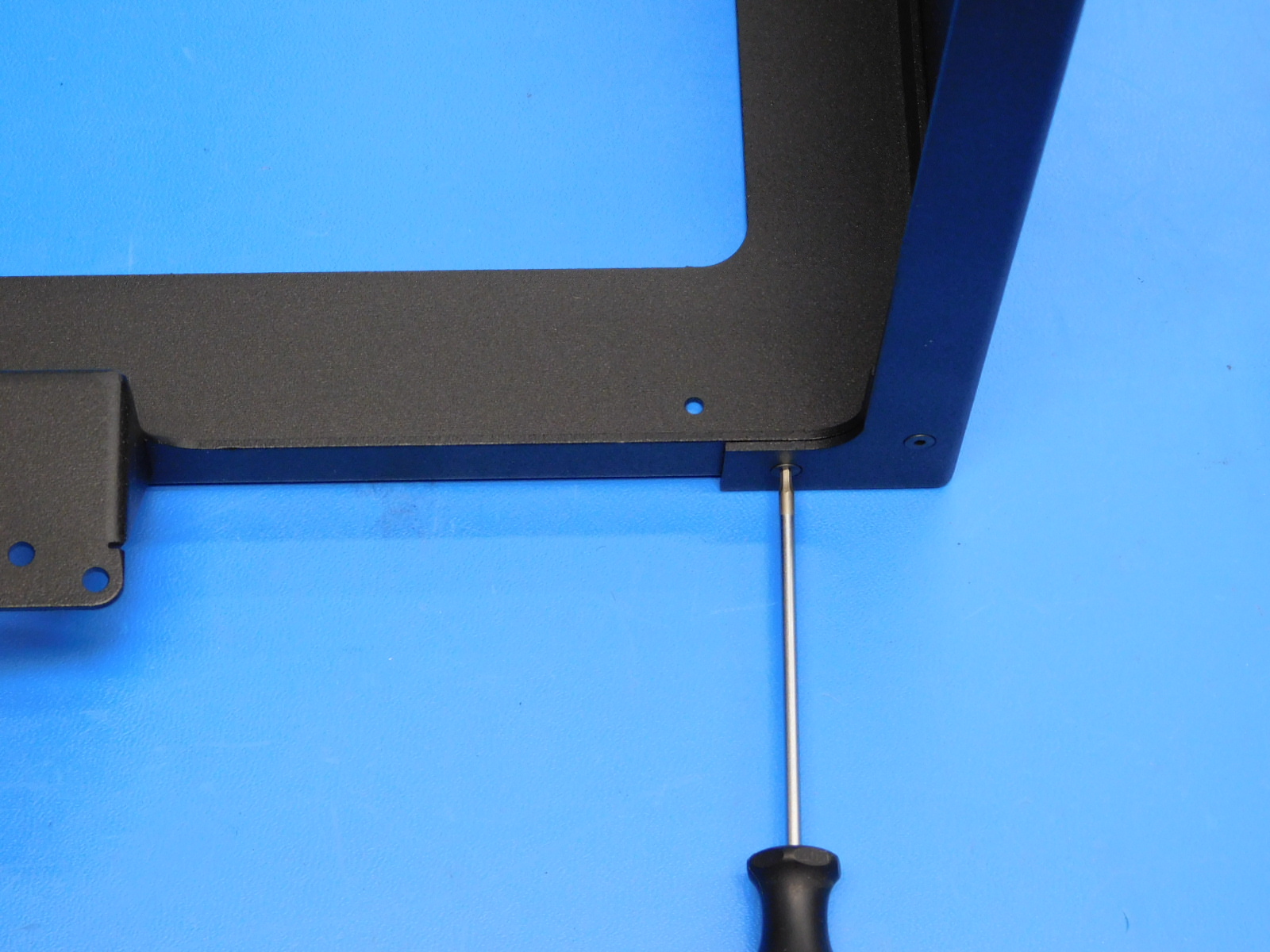
Slide the left frame [PP-FP0055] over the left side of the Bottom Frame Plate [PP-MP0149].
See [reference#3] for bottom plate orientation.
Align the holes of the two frames
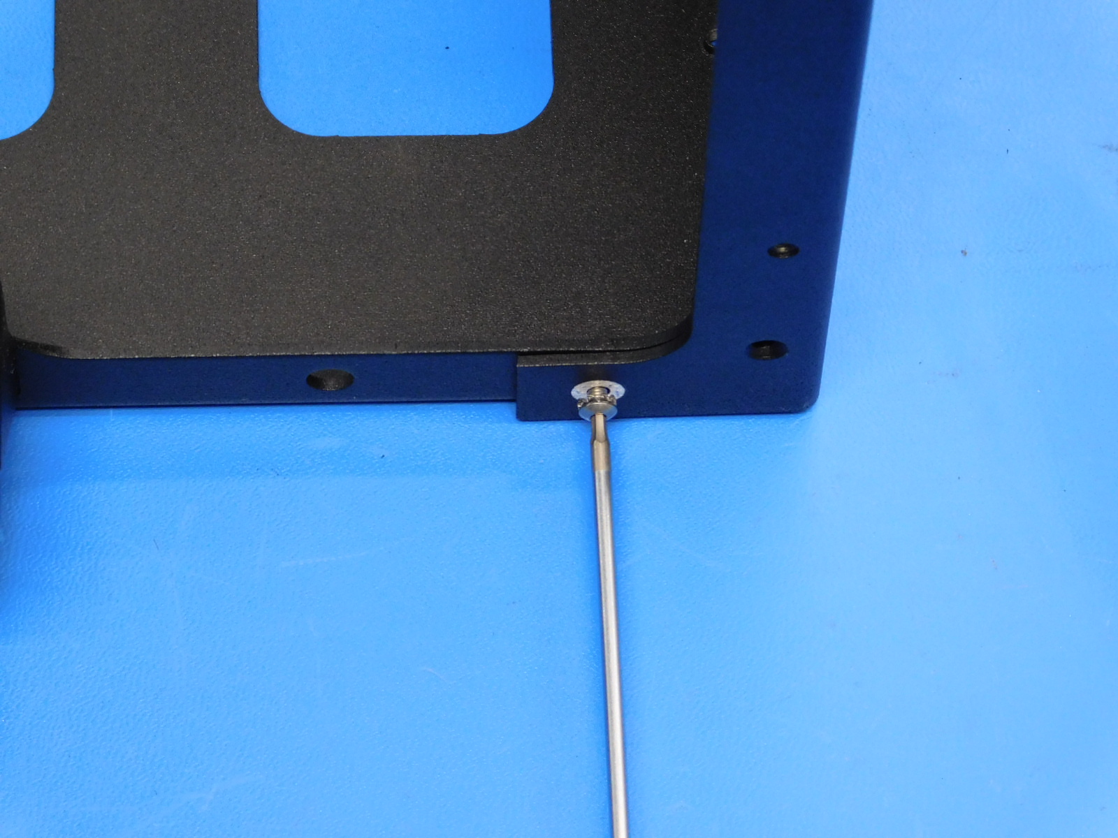
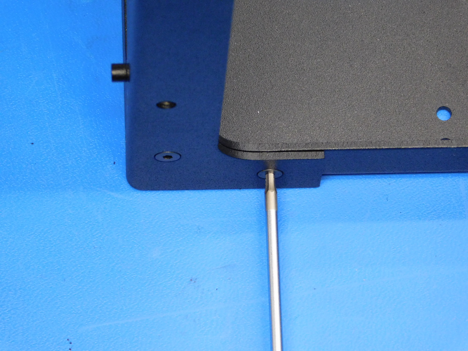
Fasten one M3x8 BHCS stainless steel screw [HD-BT0104], with star washer [HD-WA0035], into the non countersunk hole on the back of the printer that lines up with the threaded hole in the bottom plate.
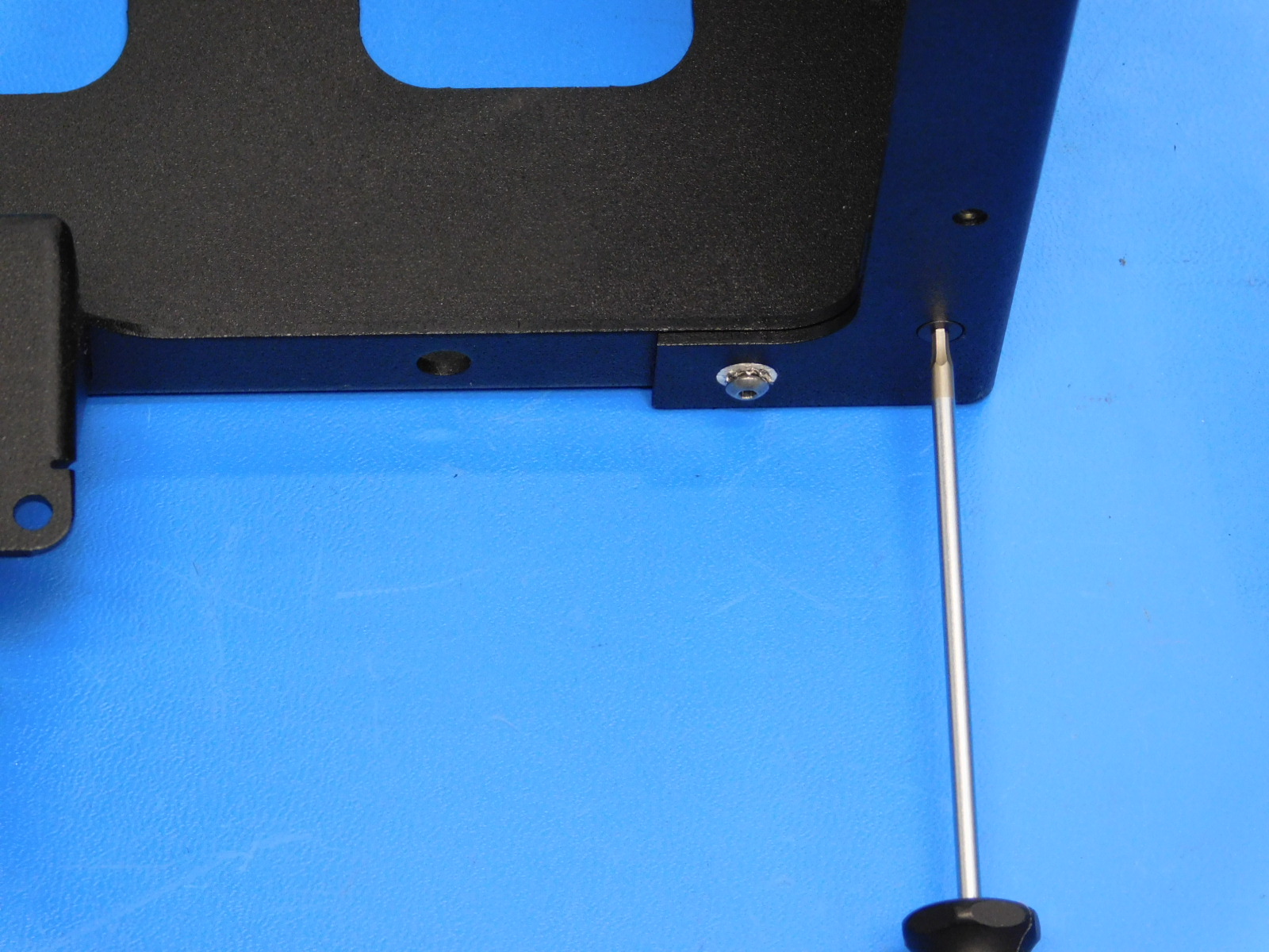
On the back of the printer (motor side), fasten one M3x6 FHCS [HD-BT0128] into the counter sunk hole on the back of the printer that lines up with the hole in the bottom frame. Torque to 5in*lbs
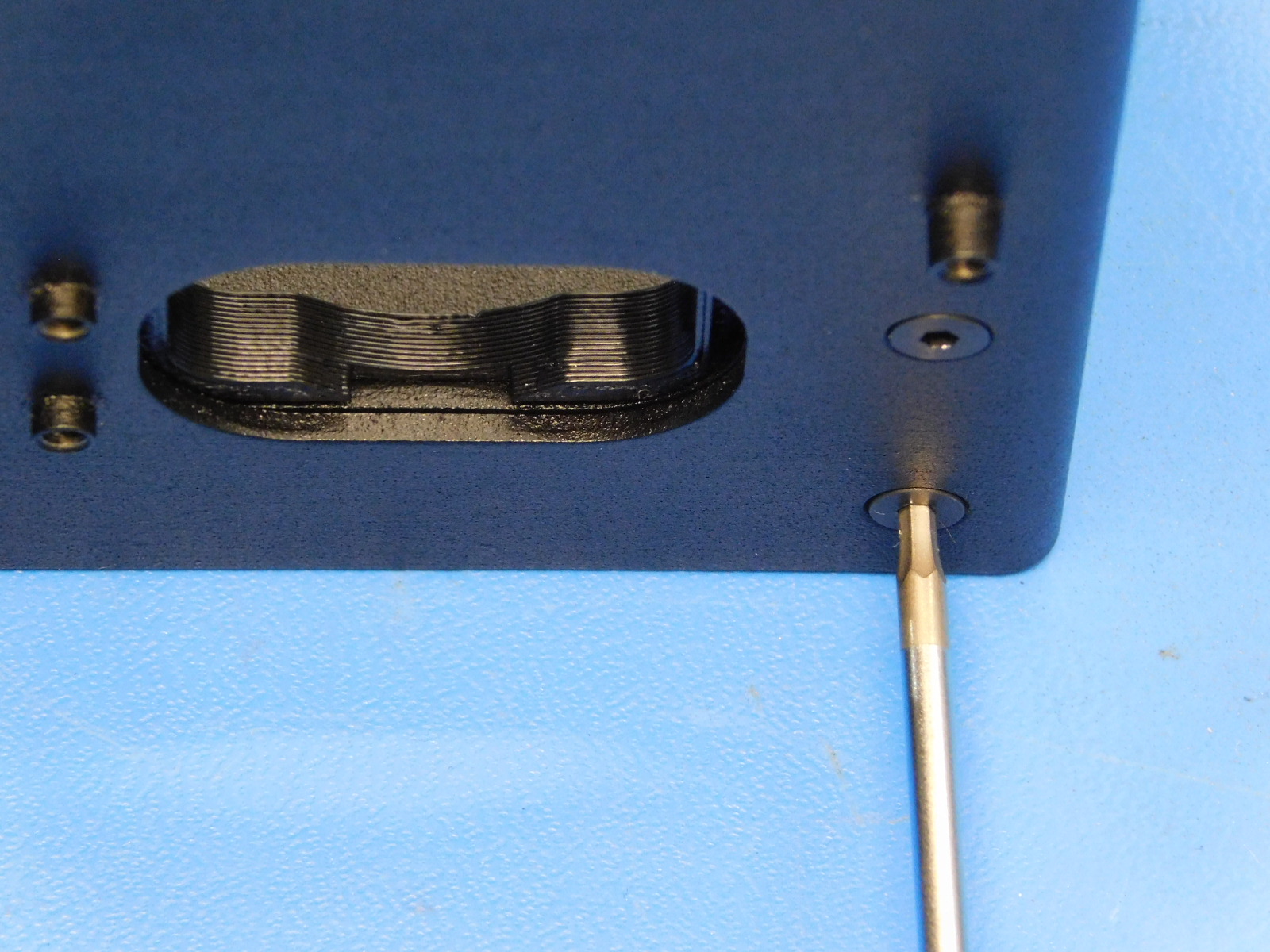
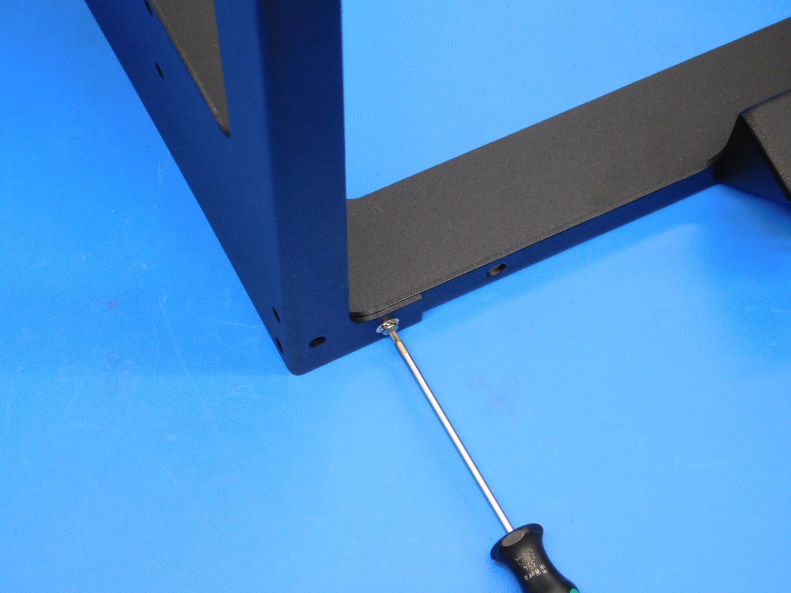
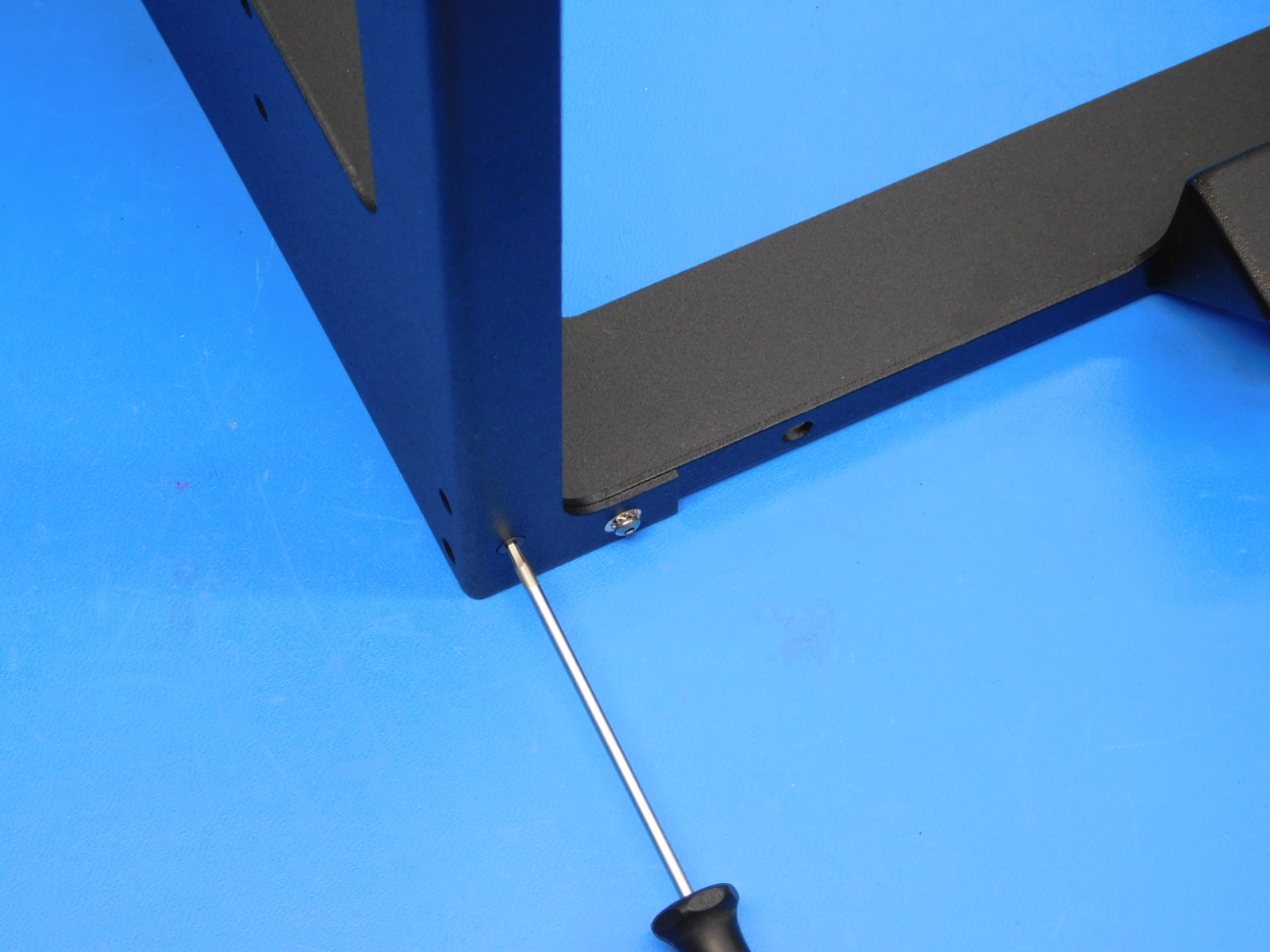
Rotate the bottom frame so the face of the left frame is facing front. Fasten two M3x6 FHCS [HD-BT0128] into the bottom right corner counter sunk holes of the left frame. Fasten two M3x6 FHCS [HD-BT0128] into the bottom left corner counter sunk holes of the left frame. Torque to 5in*lbs
Rotate the frames so that the idler side is facing front. Fasten two M3x6 FHCS [HD-BT0128] into the bottom left countersunk holes. Torque to 5in*lbs

Materials Required:
1x- [PP-FP0052] Right Frame Plate
1x- [PP-MP0149] Bottom frame plate
7x- [HD-BT0128] M3x6 FHCS
1x- [HD-BT0104] M3x8 BHCS Stainless steel
1x- [HD-WA0035] M3 External tooth serrated lock washer
Tools needed:
2mm hex driver
Slide the Right Frame Plate [PP-FP0052] over the right side of the Bottom Frame Plate [PP-MP0149].
See [reference#3] for bottom plate orientation.
Align the holes of the two frame pieces
On the back of the printer (Motor side), fasten one M3x8 BHCS stainless steel screw [HD-BT0104], with washer [HD-WA0035], into the non countersunk hole on the back of the printer that lines up with the threaded hole in the bottom plate. Torque to 5in*lbs
Fasten one M3x6 FHCS [HD-BT0128] into the counter sunk hole on the back of the printer that lines up with the hole in the bottom frame. Torque to 5in*lbs
Rotate the bottom frame so the face of the right frame is facing front. Fasten two M3x6 FHCS [HD-BT0128] into the bottom left corner counter sunk holes of the right frame. Fasten two M3x6 FHCS [HD-BT0128] into the bottom right corner counter sunk holes of the right frame. Torque to 5in*lbs
Rotate the frames so that the idler side is facing front. Fasten two M3x6 FHCS [HD-BT0128] into the bottom left countersunk holes. Torque to 5in*lbs
Materials Required:
12x- [HD-BT0128] M3x6 FHCS
2x- [HD-BT0104] M3x8 BHCS SST
2x- [HD-WA0035] M3 External Tooth serrated lock washer
Tools needed:
2mm hex driver
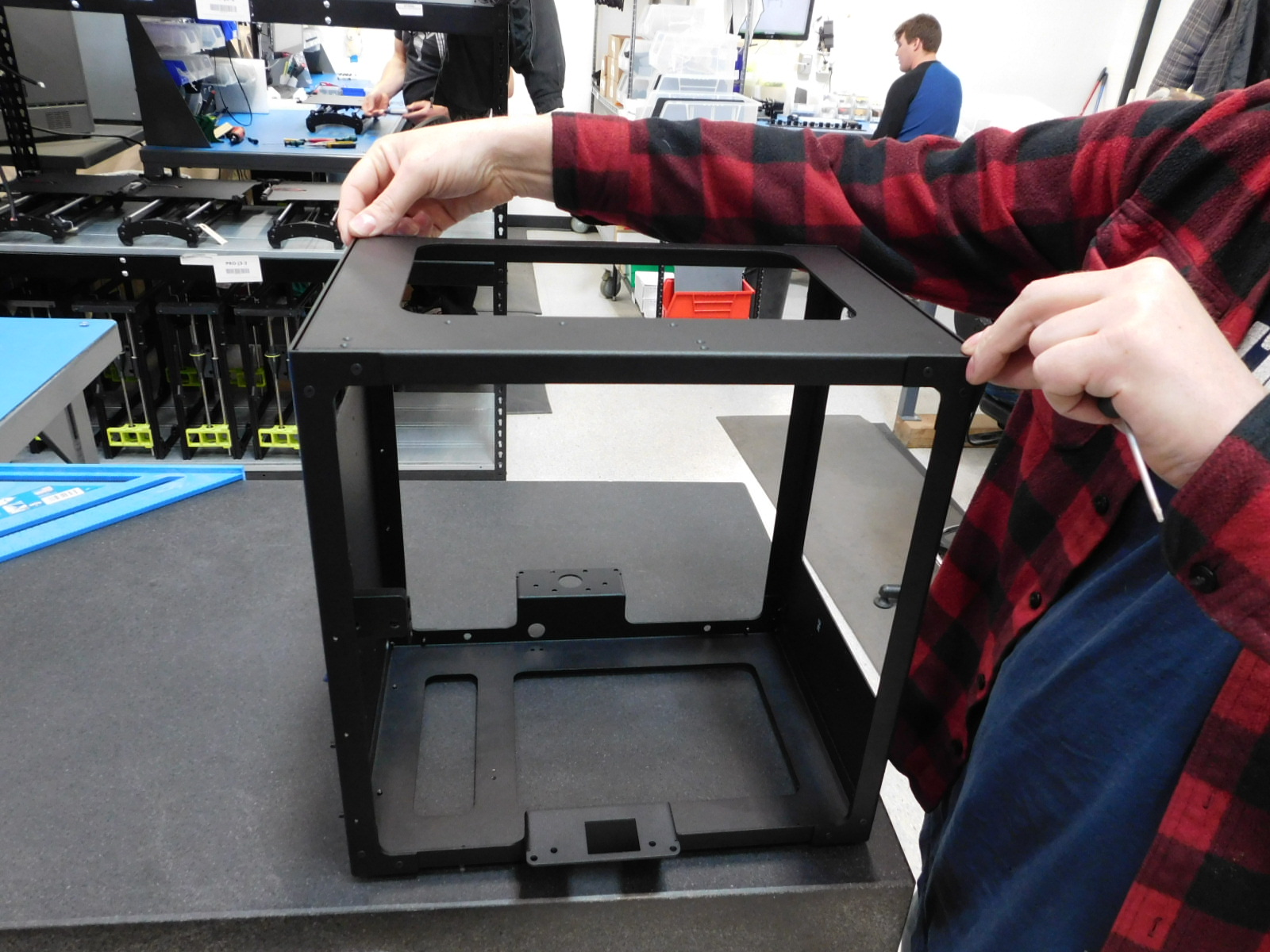
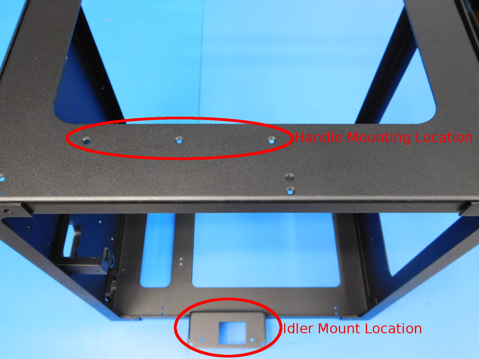
Slide the Top Frame Plate [PP-FP0051] in between the Left and Right frame plates. Ensure the handle mounting location on the top frame is oriented to the front ( idler side) of the printer.
Align the holes in the frame pieces
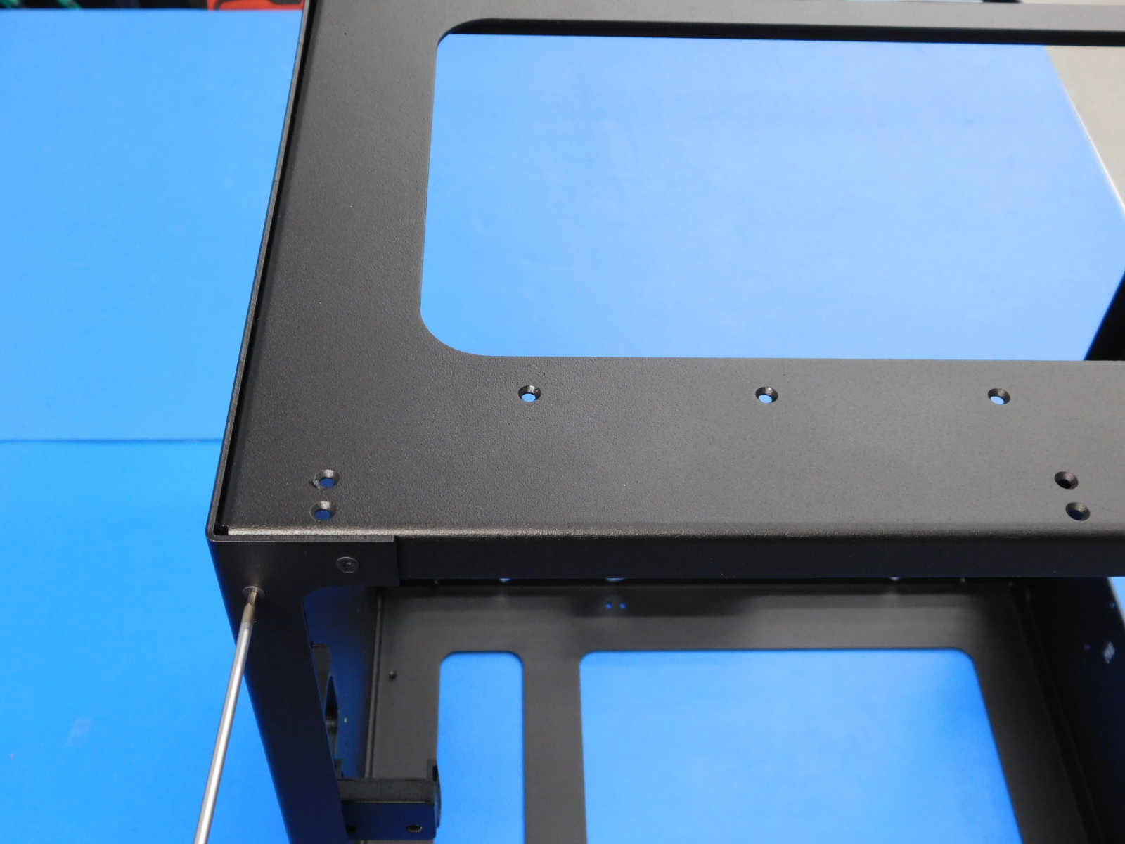
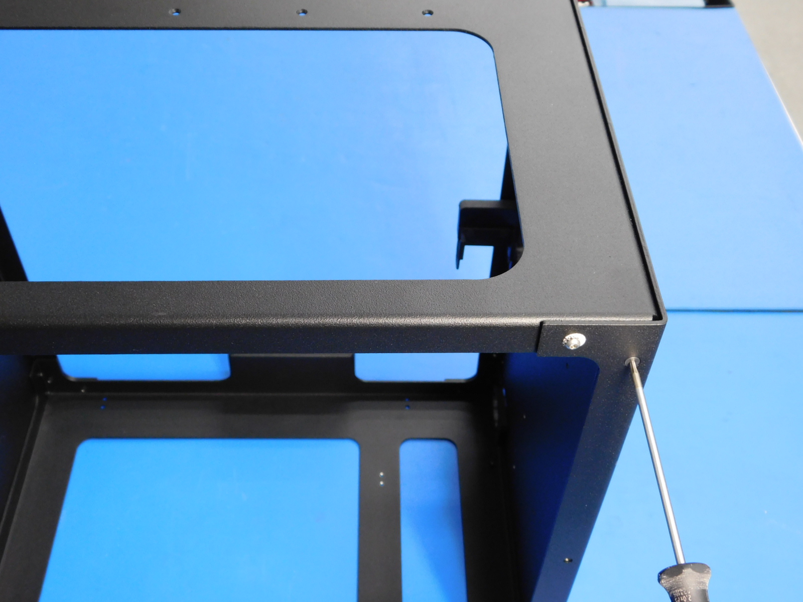
On the front (idler side), fasten two M3x6 FHCS [HD-BT0128] screws into the top left corner
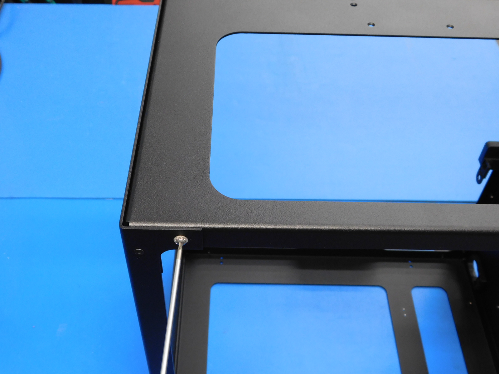
Rotate the frames so the motor side is on the left and the idler side is on the right. Fasten two M3x6 FHCS [HD-BT0128] screws into the top right corner. Fasten two M3x6 FHCS [HD-BT0128] screws into the top left corner.
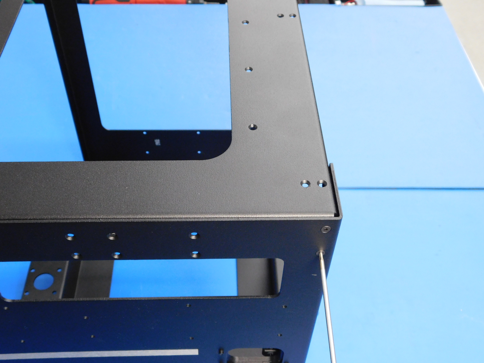
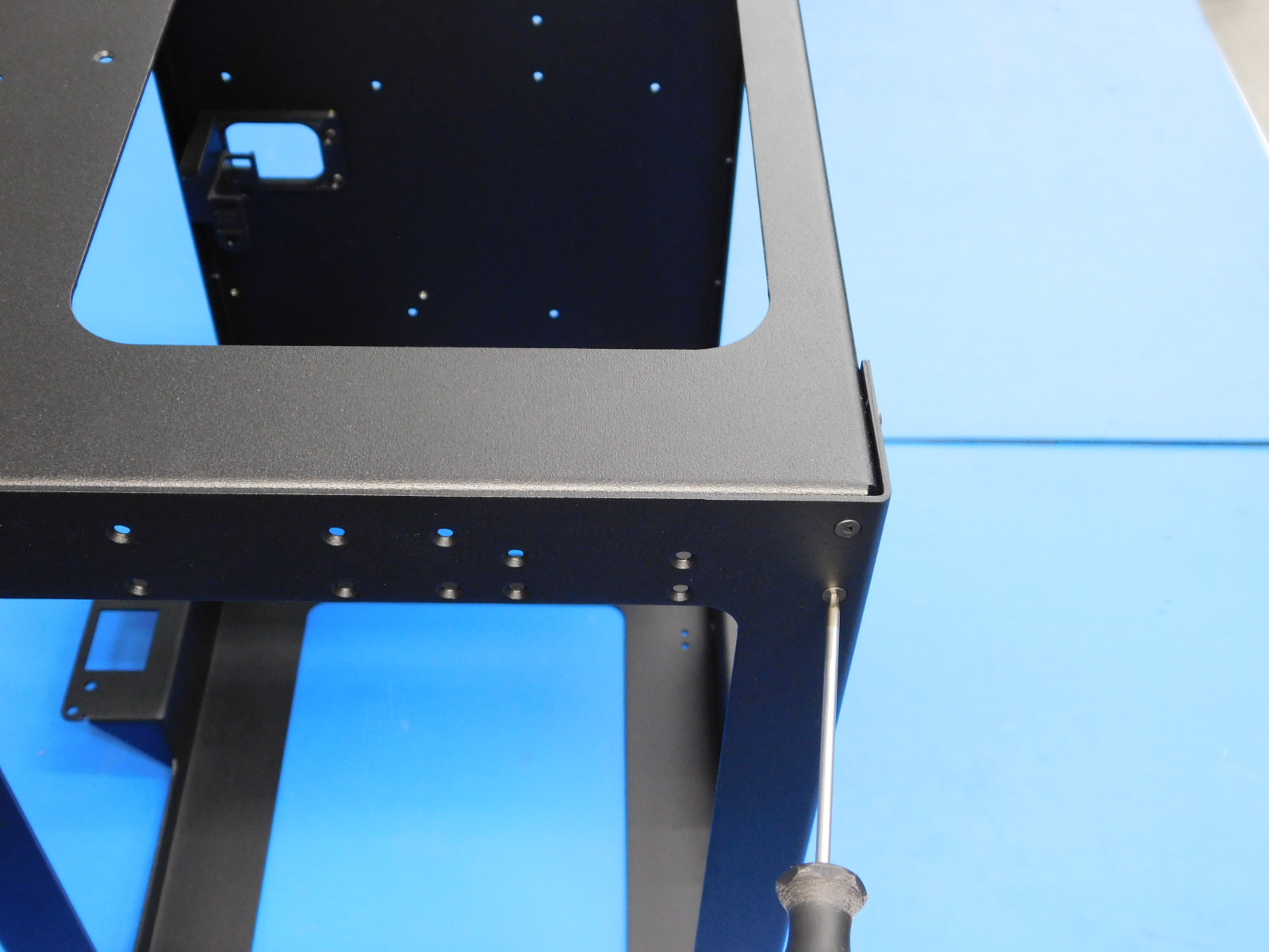
Rotate the frames so the motor side is in facing front. Fasten one M3x8 BHCS stainless steel screw [HD-BT0104], with star washer [HD-WA0035], into the non countersunk hole in the top right corner. Fasten one M3x6 FHCS [HD-BT0128] screw into the top right corner. Fasten one M3x6 FHCS screw [HD-BT0128] into the top left corner. Fasten one M3x8 BHCS stainless steel screw [HD-BT0104], with star washer [HD-WA0035], into the non countersunk hole in the top left corner.
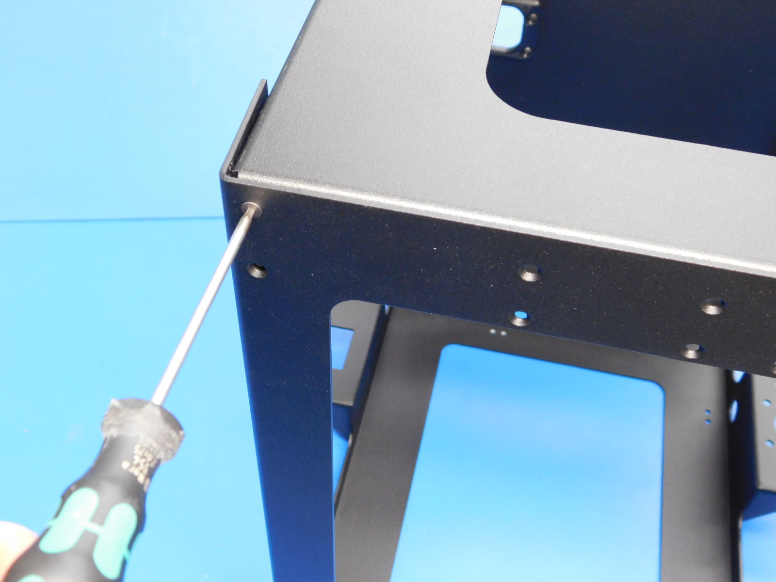
Rotate the frames so the motor side is on the right and the idler side is on the left. Fasten two M3x6 FHCS [HD-BT0128] screws into the top right corner. Fasten one M3x6 FHCS [HD-BT0128] screw into the top left corner.
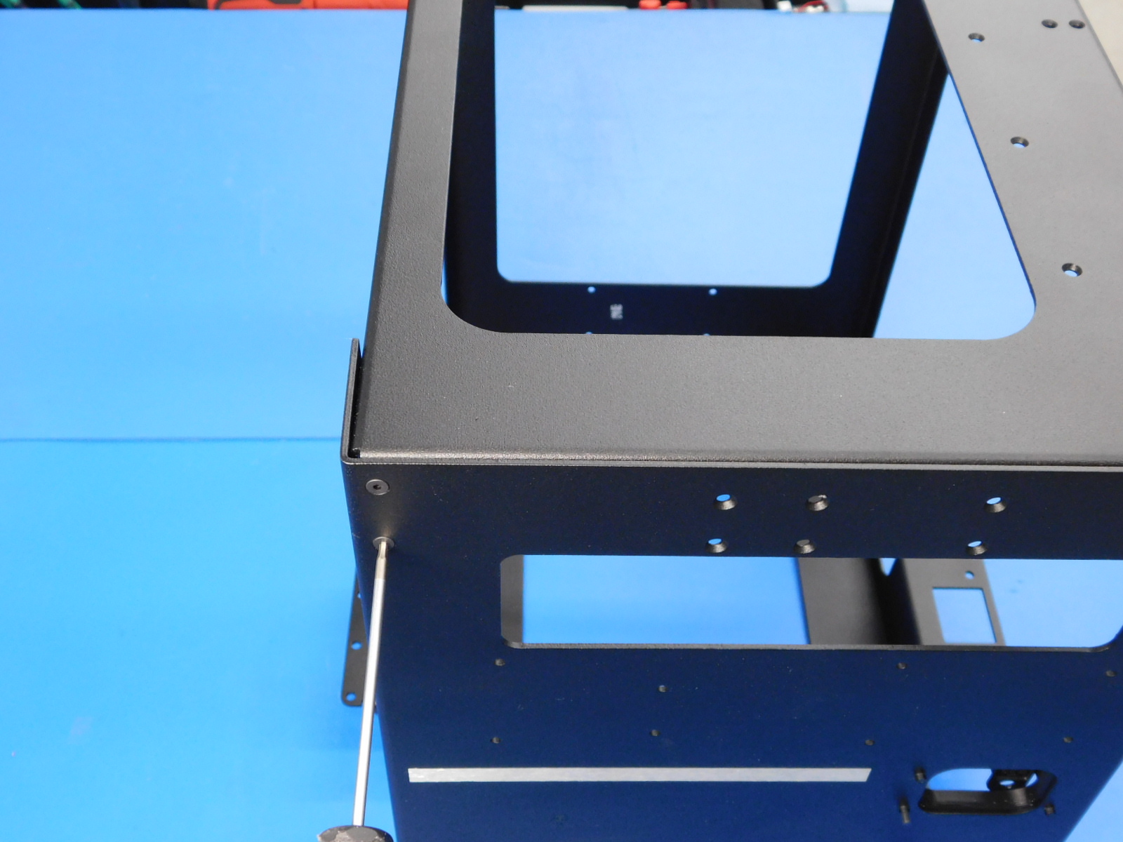
Rotate the frames so the idler is in facing front. Fasten one M3x6 FHCS [HD-BT0128] screws into the right-most screw location on the top right corner.
Note: 2 screw holes on the frame's top front right corner should be empty, these are for the LCD display installed at Final Electrical Assembly, See [reference#4]

Materials Required:
1x- [PP-IS0061] Mini Handle, Complete
3x- [HD-BT0128] M3x6 FHCS
Tools needed:
2mm hex driver
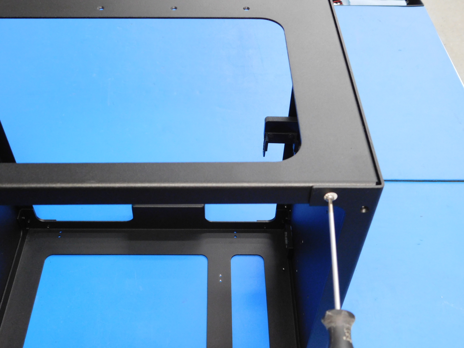
Line the handlebar with the three holes in the top frame plate towards the front.
Secure the handle by fastening three M3x6 FHCS [HD-BT0128] through the counter sunk holes in the frame into the threaded inserts in the handle. Torque to 5in*lbs
Materials Required:
4x- [HD-MS0054] Rubber bumper square
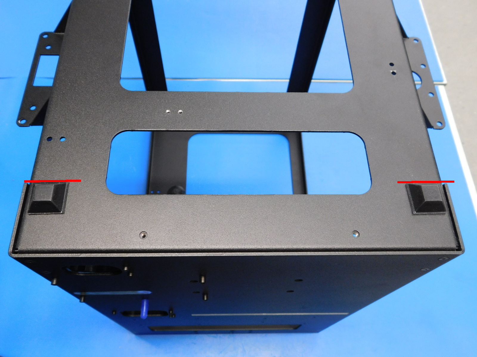
Flip the printer onto the top frame
Place two rubber bumper squares in the front corner and back corner on the right frame side.
Place two rubber bumper squares in the front corner and back corner of the left frame side.
The squares need to be aligned with the left frame brackets. See [reference#5]
Check the Frame Assembly to ensure that the frame is square and does not teeter;
Set the frame on the granite leveling block and press on opposite top corners to ensure all four rubber feet of the frame rest flat on the block.