Open HardwareAssembly Instructions
Guides for installation and assembly of the LulzBot line of products made by Aleph Objects, Inc.
Guides for installation and assembly of the LulzBot line of products made by Aleph Objects, Inc.
Materials required:
1x- [AS-EL0002] Hibiscus LCD Assembly
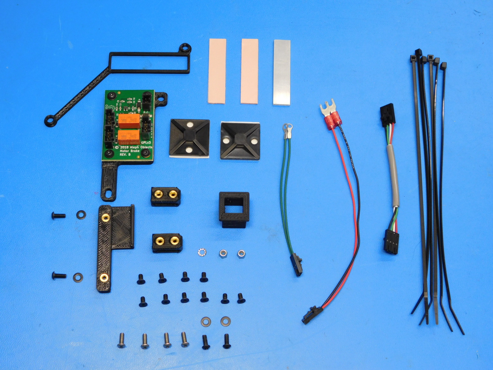
1x- [AS-EL0003] Z-Motor Brake - Assembled
1x- [AS-PR0102] Mini 2, Electrical Cover Assembly
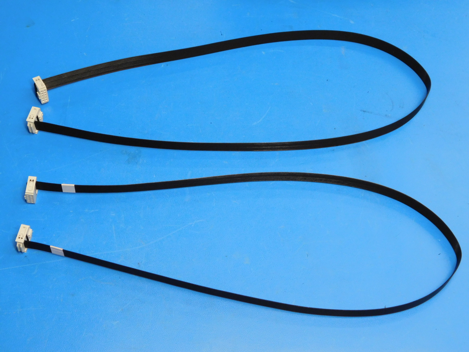
1x- [AS-CB0083] Mini 2 LCD Harness 1
1x- [AS-CB0084] Mini 2 LCD Harness 2
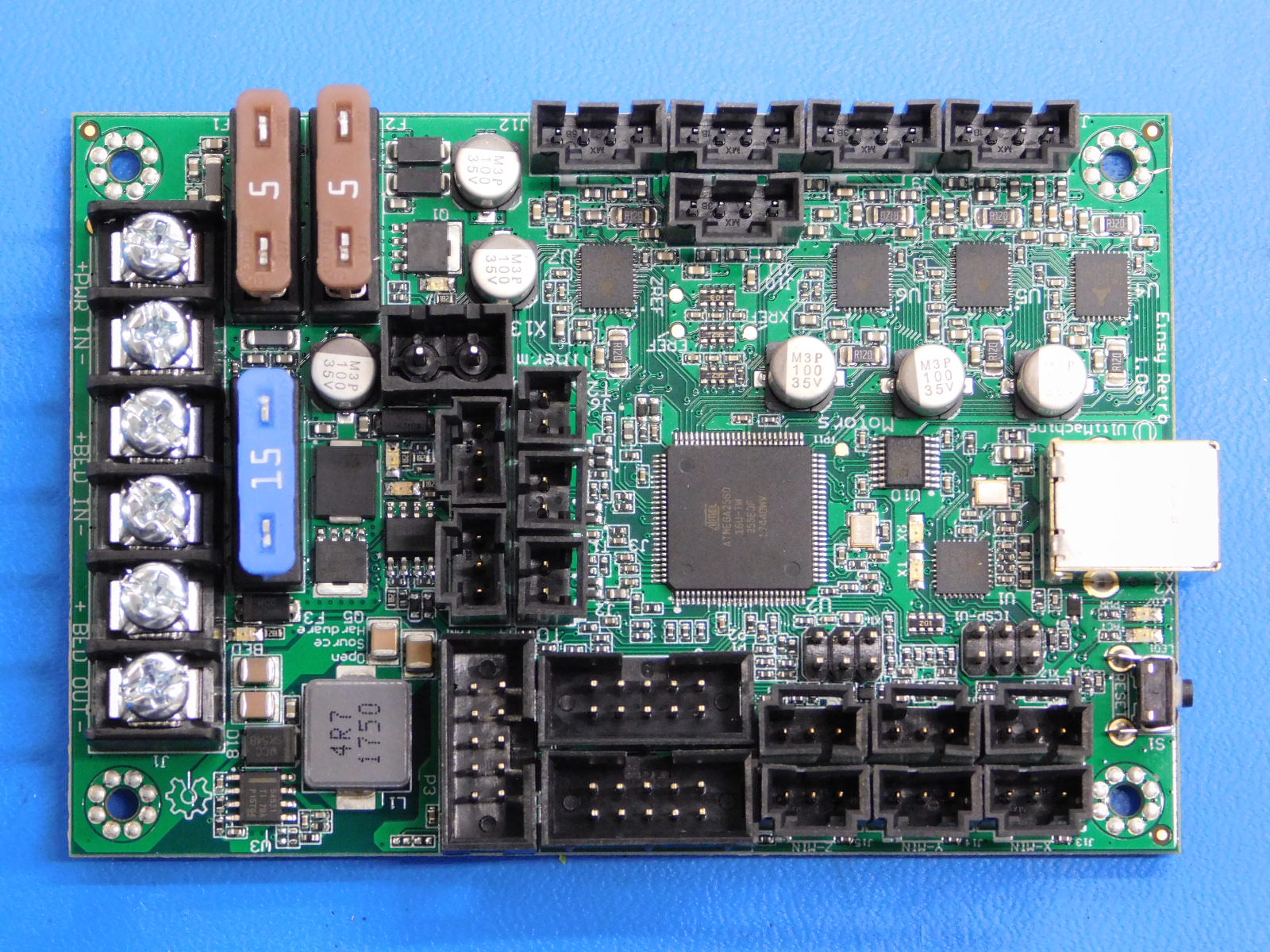
1x- [PC-AS0054] EinsyRetro 1.0a
1x- [PP-GP0247] USB Support
4x- [HD-BT0104] M3x8 SST BHCS
2x- [HD-MS0249] UV Resistant Cable Tie Downs
Xx- [HD-MS0058] 8" Zip Tie
2x- [HD-NT0001] M3 Nyloc Nut
1x- [HD-WA0035] M3 External Tooth Lock Washer
1x- [AS-CB0069] Z-Brake Power Harness
1x- [AS-CB0070] Z-Brake Motor Harness
1x- [PP-GP0338] Heatsink frame
1x- [PP-MP0210] Heatsink
2x- [HD-MS0463] Thermal Gap Filler
2x- [PP-IS0054] Top Cable Bracket w/ Inserts
1x- [PP-IS0055] Side Cable Bracket w/ Inserts
4x- [HD-WA0038] M3 Washer
4x- [HD-BT0137] M3x8 BHCS
10x- [HD-BT0128] M3x6 FHCS
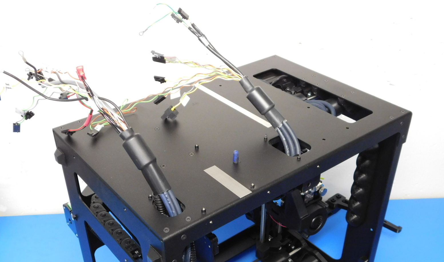
Place the machine on the right side frame plate with the spool arm in the up position, so that the left plate is facing up.
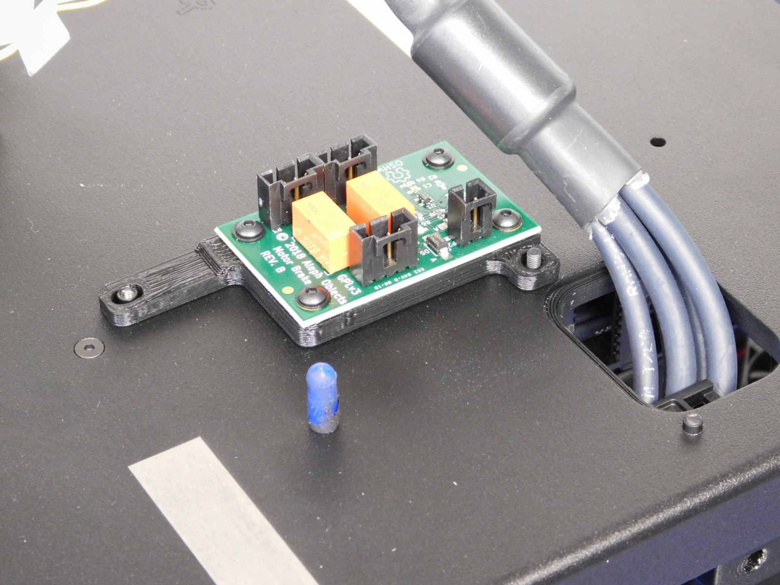
Place the Z-Brake [AS-EL0003] on the left plate, as pictured.
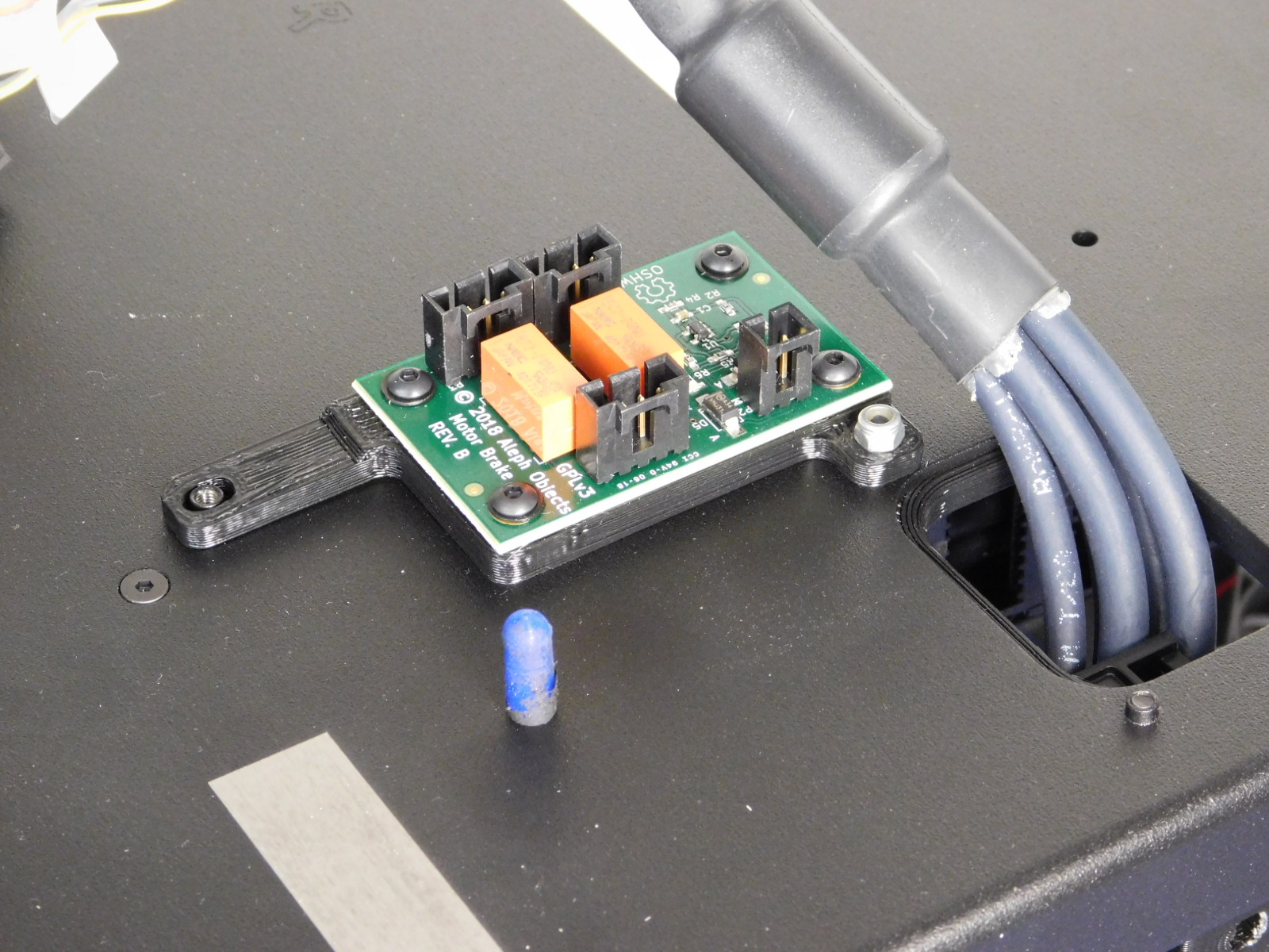
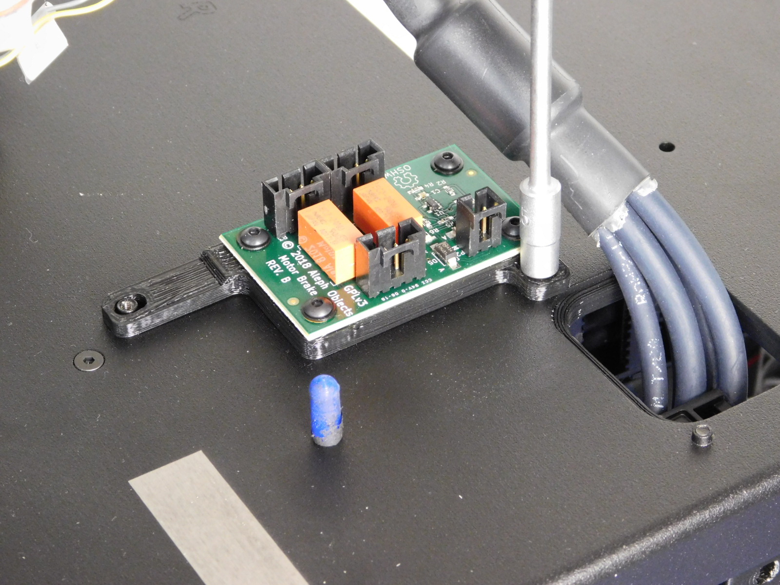
Secure the top of the Z-Brake to the location shown using one M3 Nyloc Nut [HD-NT0001]
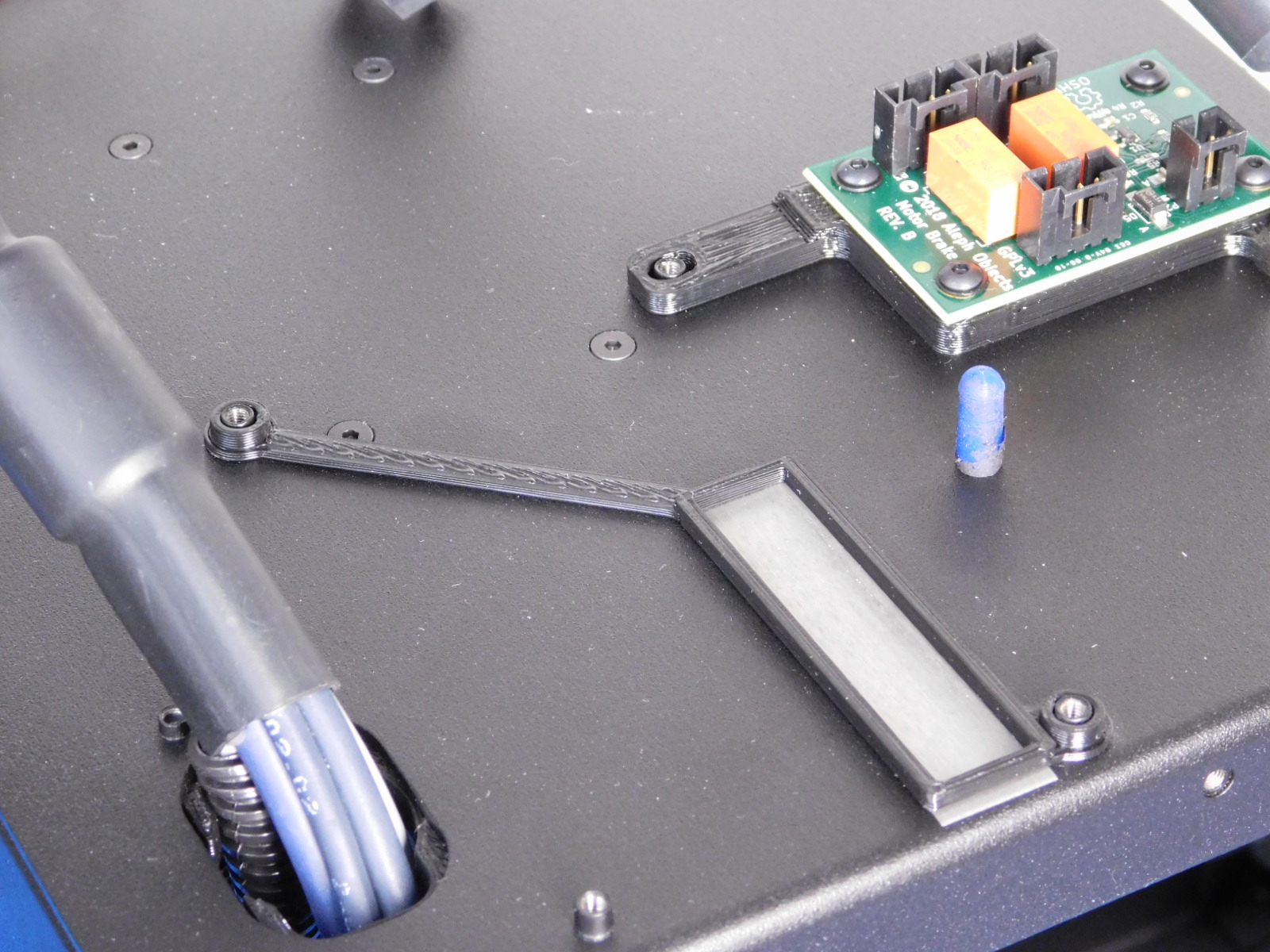
Place the Heatsink Frame [PP-GP0338] on the left frame plate, as pictured.
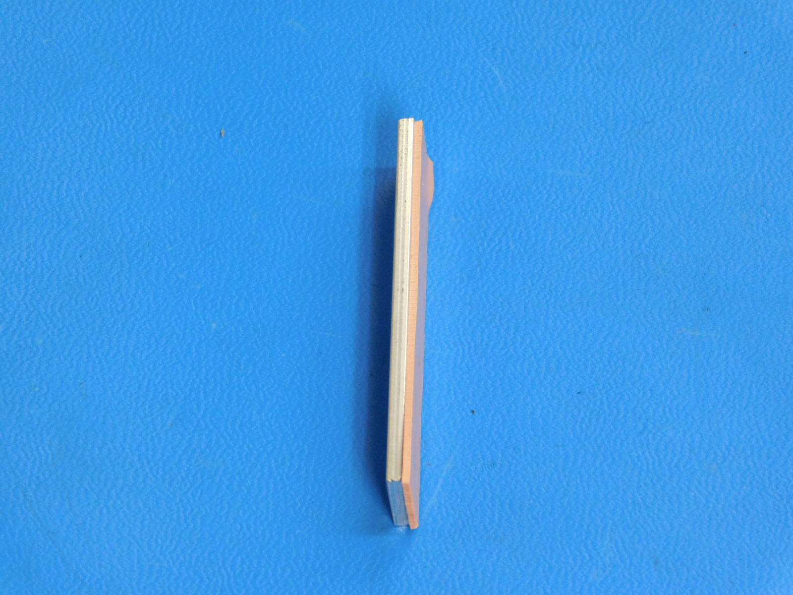
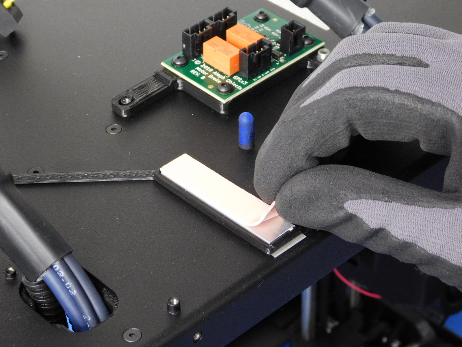
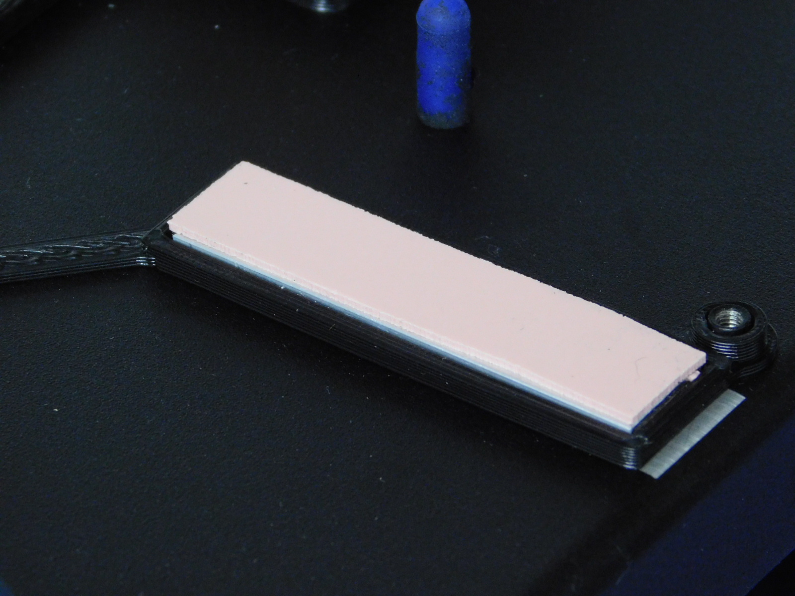
Apply Thermal Gap Filler [HD-MS0463] to one side of the Heatsink [PP-MP0210] as pictured.
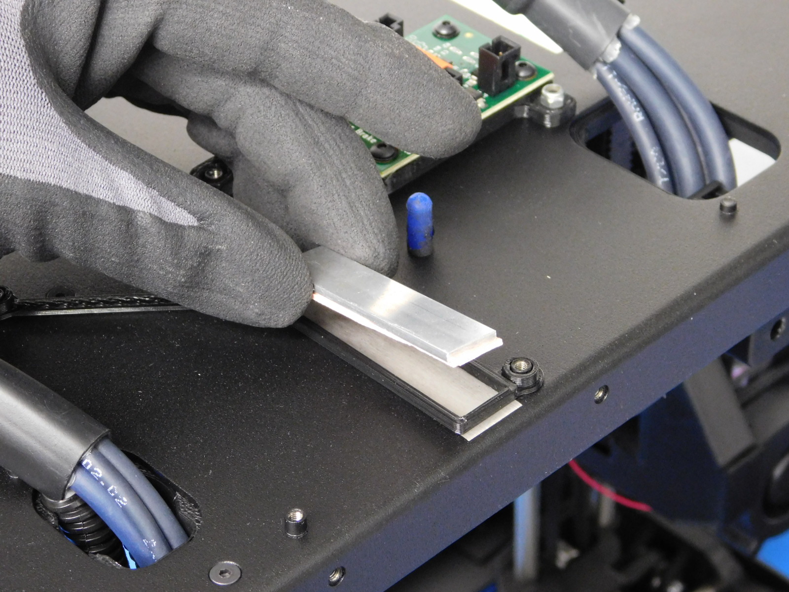
Place the Heatsink [PP-MP0210] inside the Heatsink Frame [PP-GP0338], press down firmly.
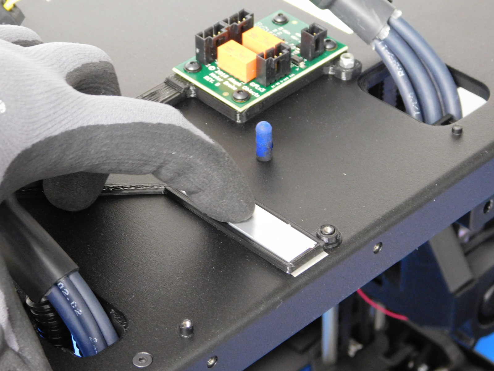
Apply Thermal Gap Filler [HD-MS0463] to the top of the Heatsink [PP-MP0210] as pictured.
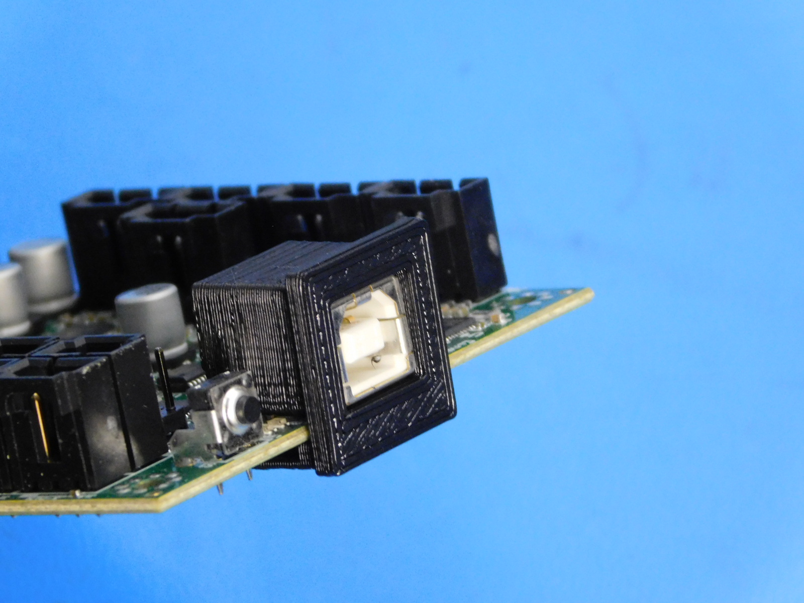
Install the USB Support [PP-GP0247] onto the EinsyRetro Board [PC-AS0054] as pictured.
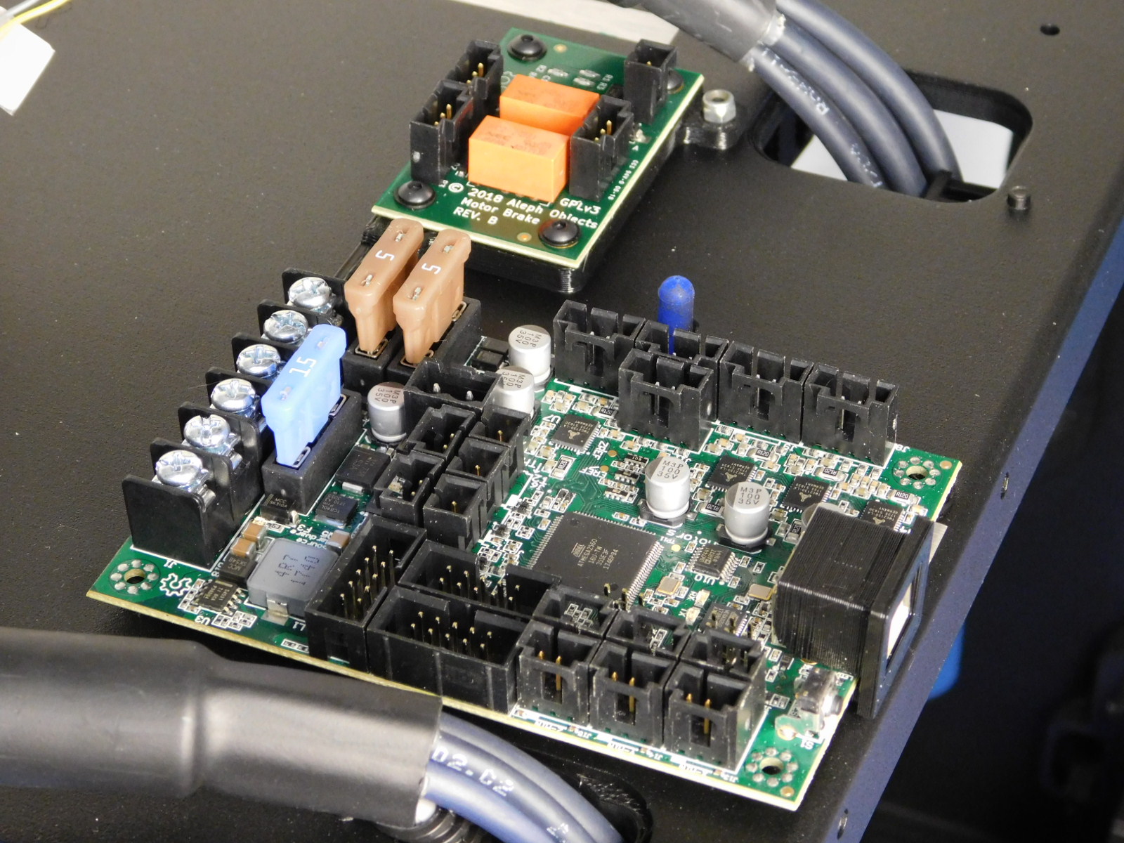
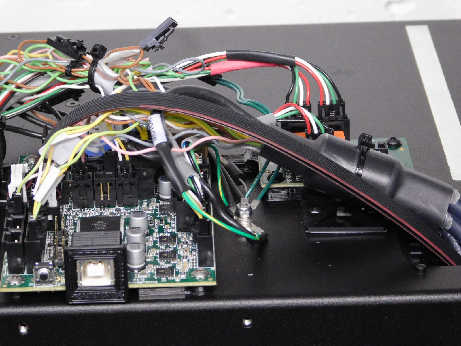
Place the EinsyRetro [PC-AS0054] on the left plate (over the heat sink installed in the previous step), aligning with the stand-offs as pictured.
Secure with 4x M3x8 SST BHCS; torque to 5in*lbs.
Install one cable tie down onto the left plate just below the upper strain relief along the right edge of the Z-Brake as pictured.
Install the second tie down just under the bottom left board mounting standoff, oriented along the bottom edge of the EinsyRetro. The tie down should be flush with the left edge of the EinsyRetro as pictured.

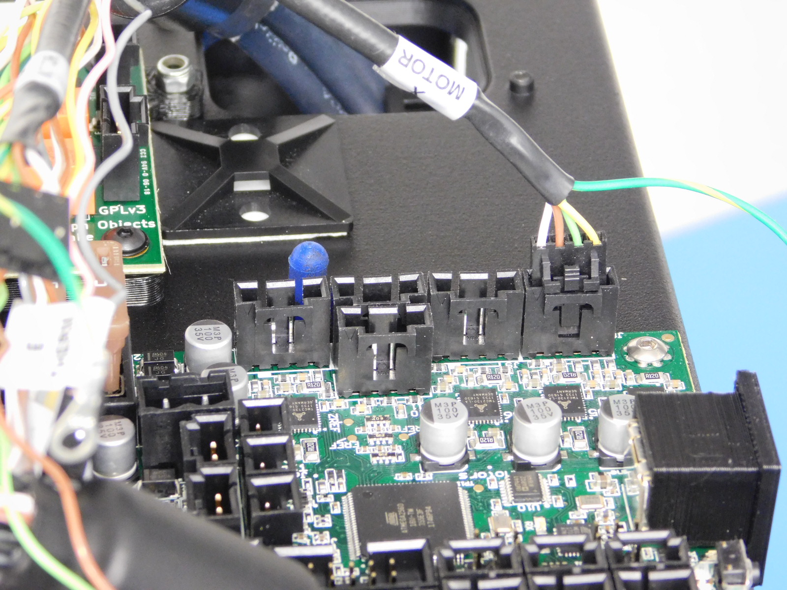
Plug in motor leads to the EinsyRetro control board as follows:
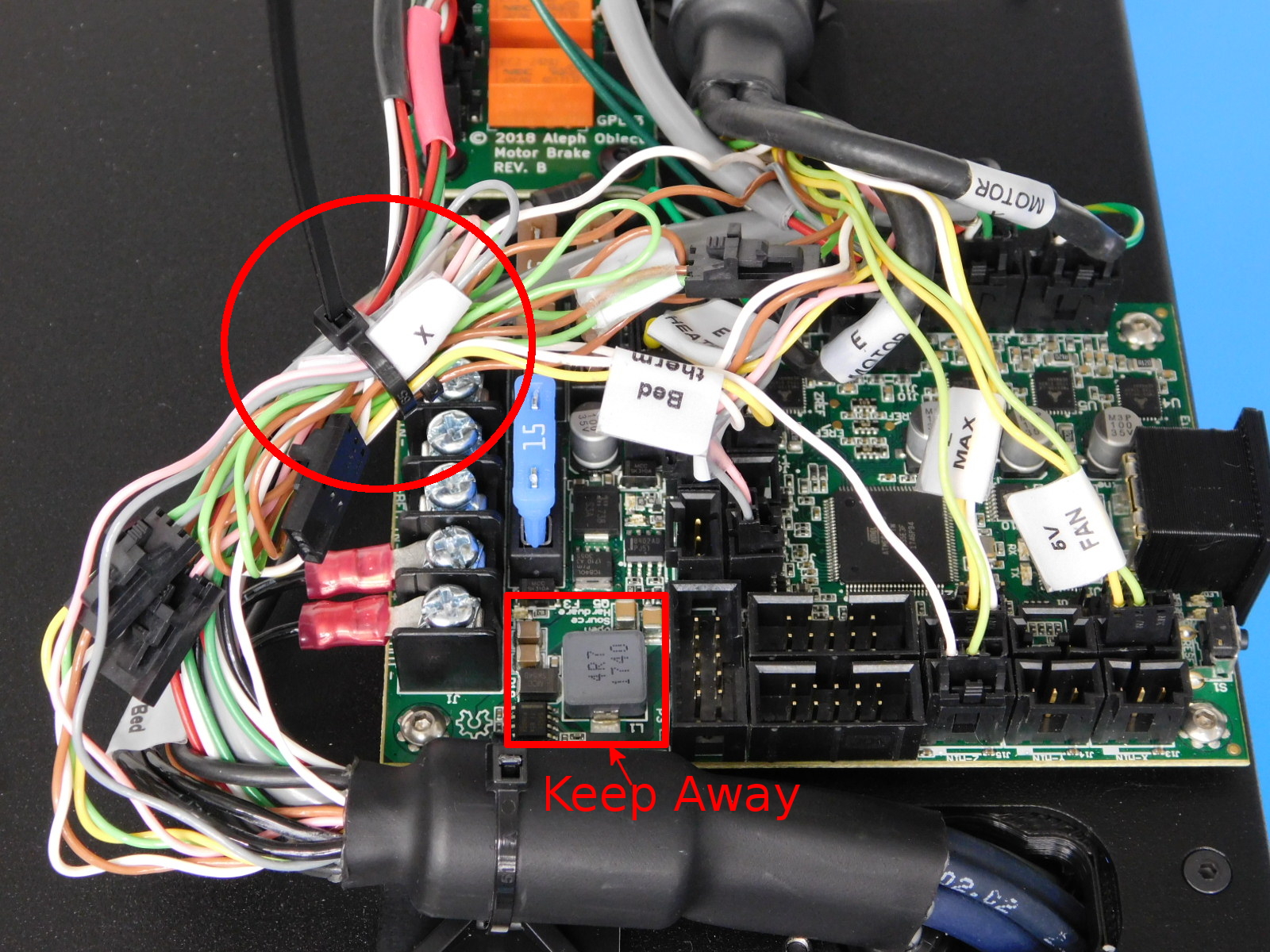
First locate the 4 pin Molex connector labeled “X Motor” and plug it into the board as pictured.
Locate the 4 pin Molex connector on the lead with grey jacket up to the connector; this is Y-Motor. Connect it to the board as pictured, to the left of the X-Motor connection.
Locate the two 4 pin Molex connectors with red and black heatshrink, these are Z-Motors. Connect these two to the left two connections on the Z-Brake board as pictured.
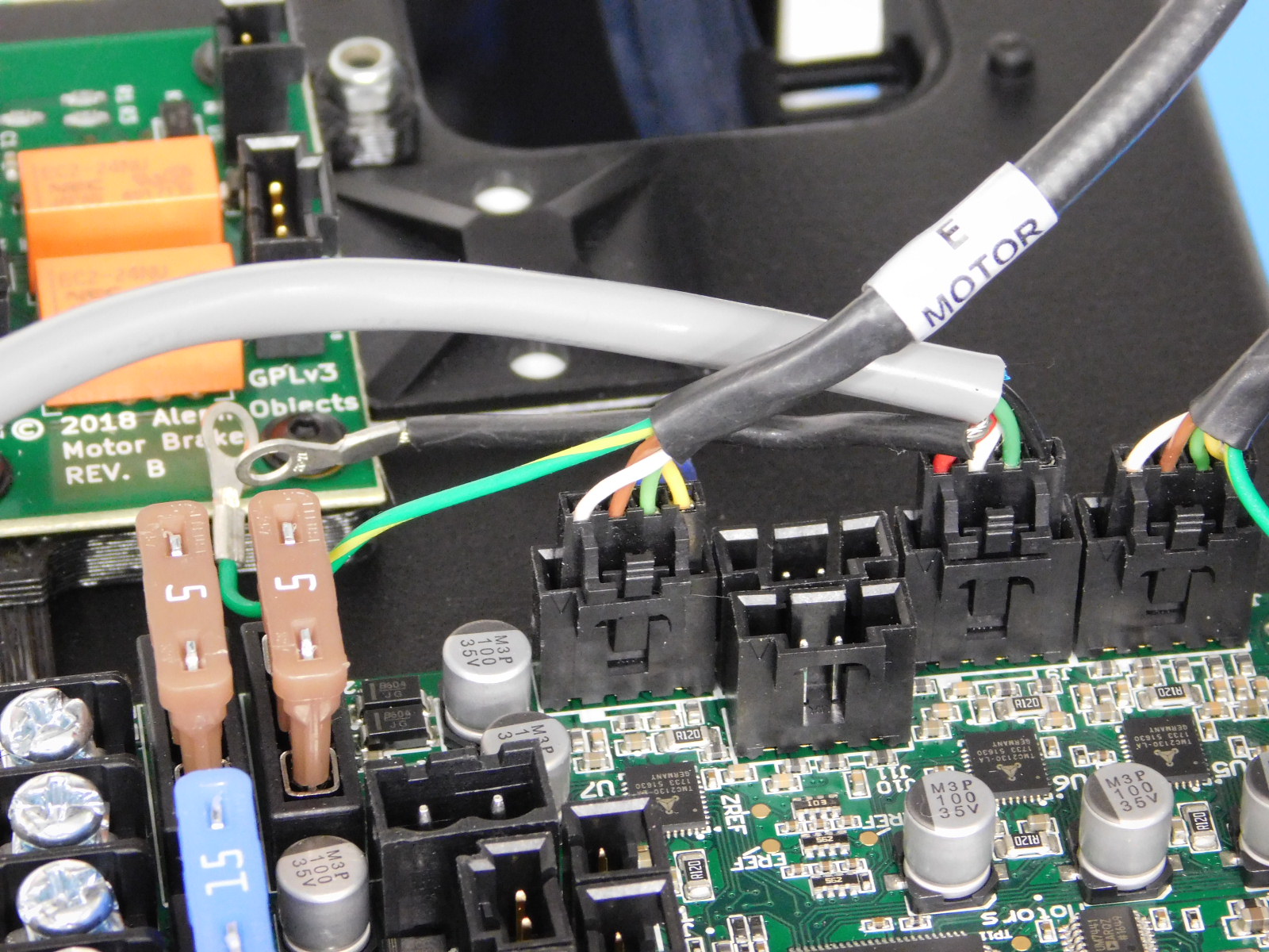
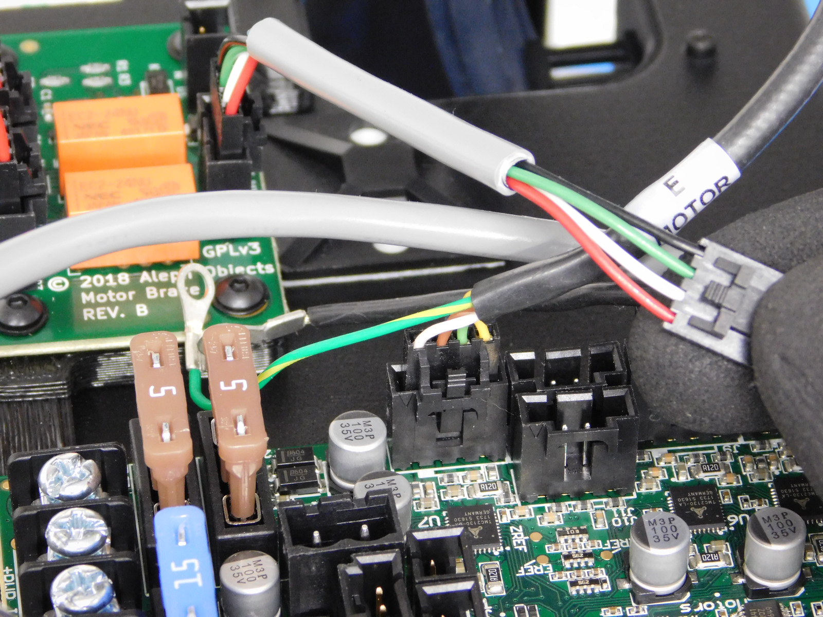
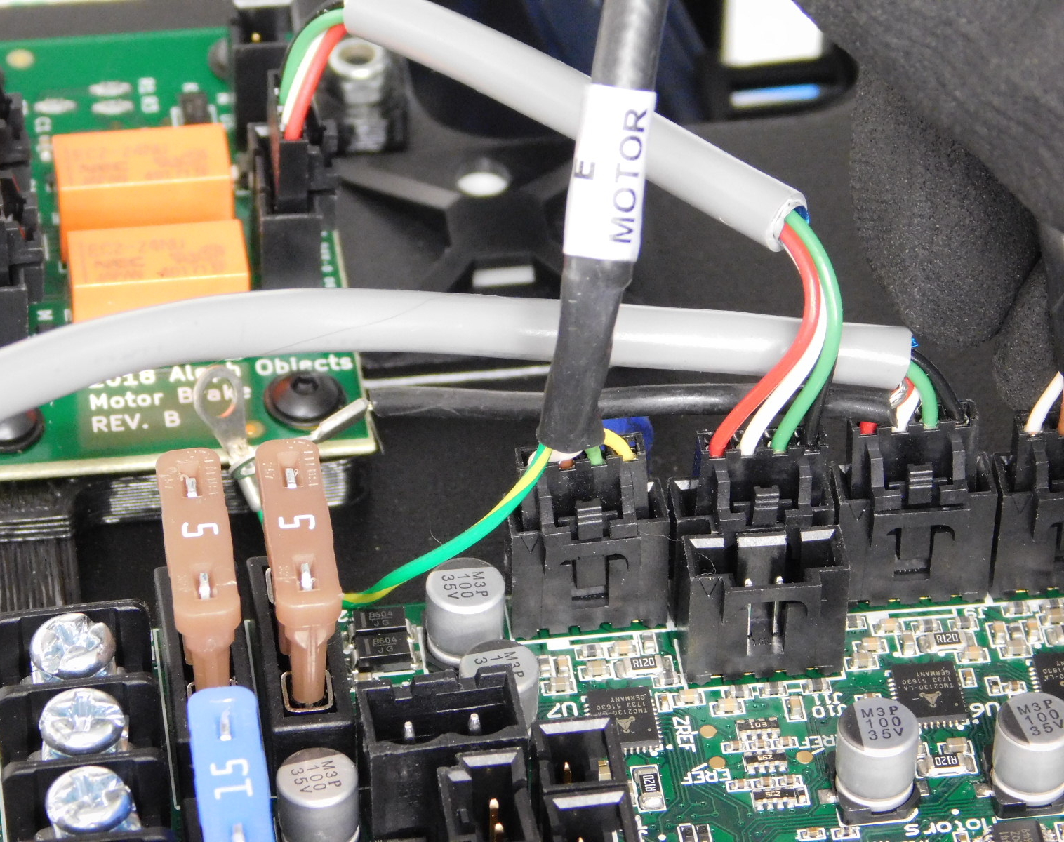
Locate the 4 pin Molex connector labeled “E Motor” and plug it into the board as pictured.
Connect Z-Brake Motor Harness [AS-CB0070] to the right side connection of the Z-Brake board. Connect the other end of the Z-Brake Motor Harness [AS-CB0070] to the EinsyRetro control board as pictured.


Connect the Extruder & Bed Heater leads to the EinsyRetro board as follows:
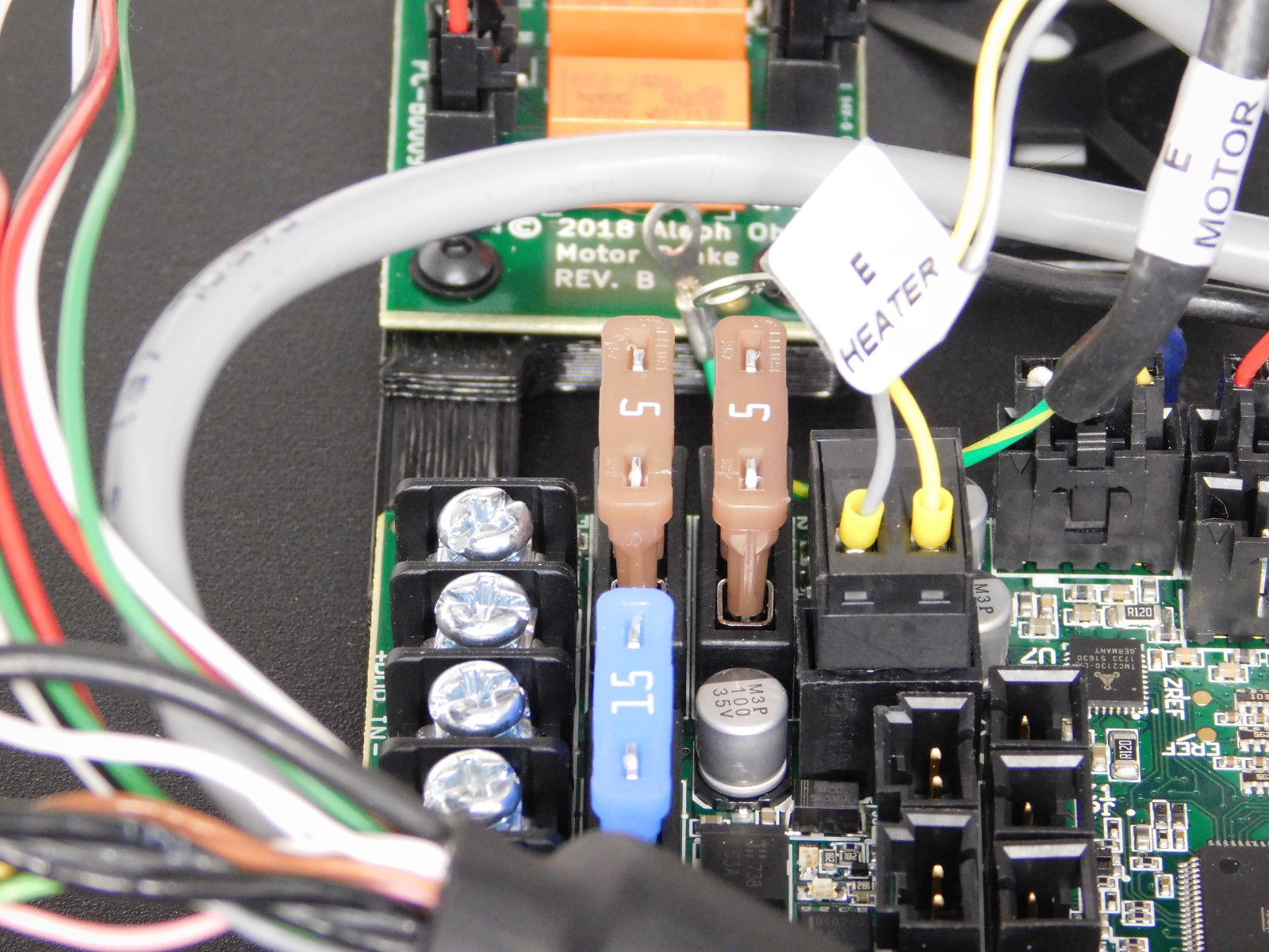
Locate the 2 pin terminal block plug labeled “E Heater” and plug in as pictured.
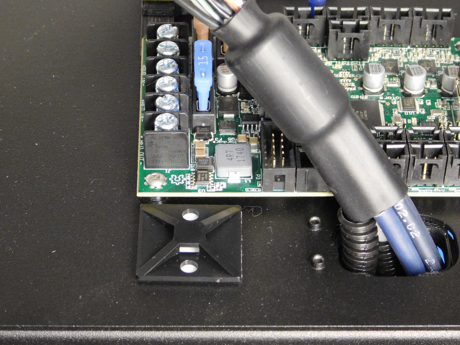
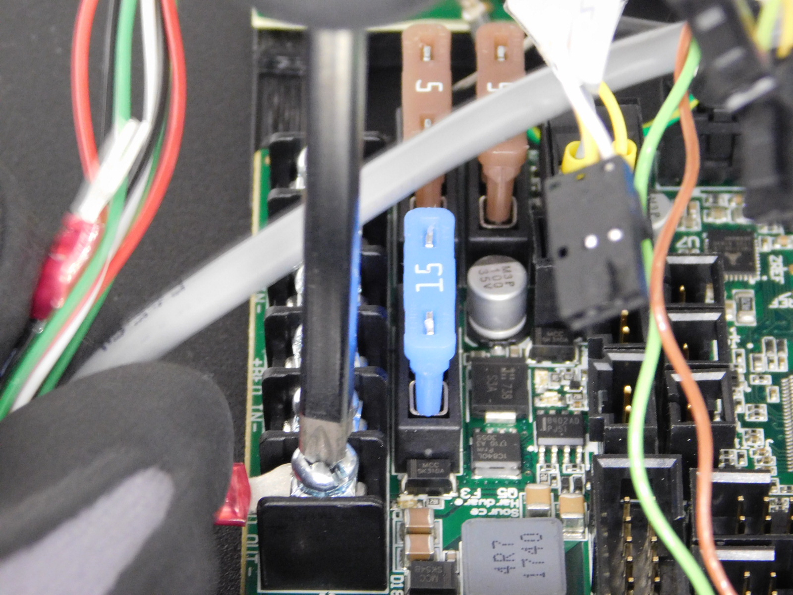
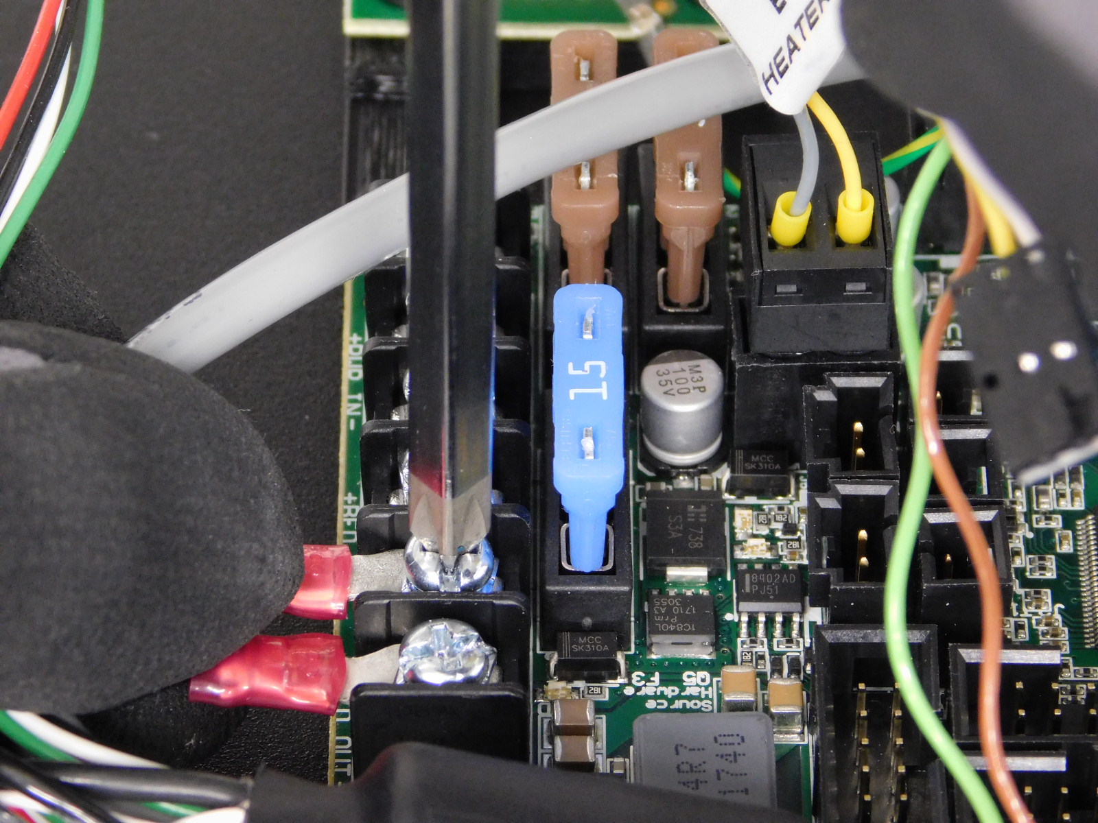
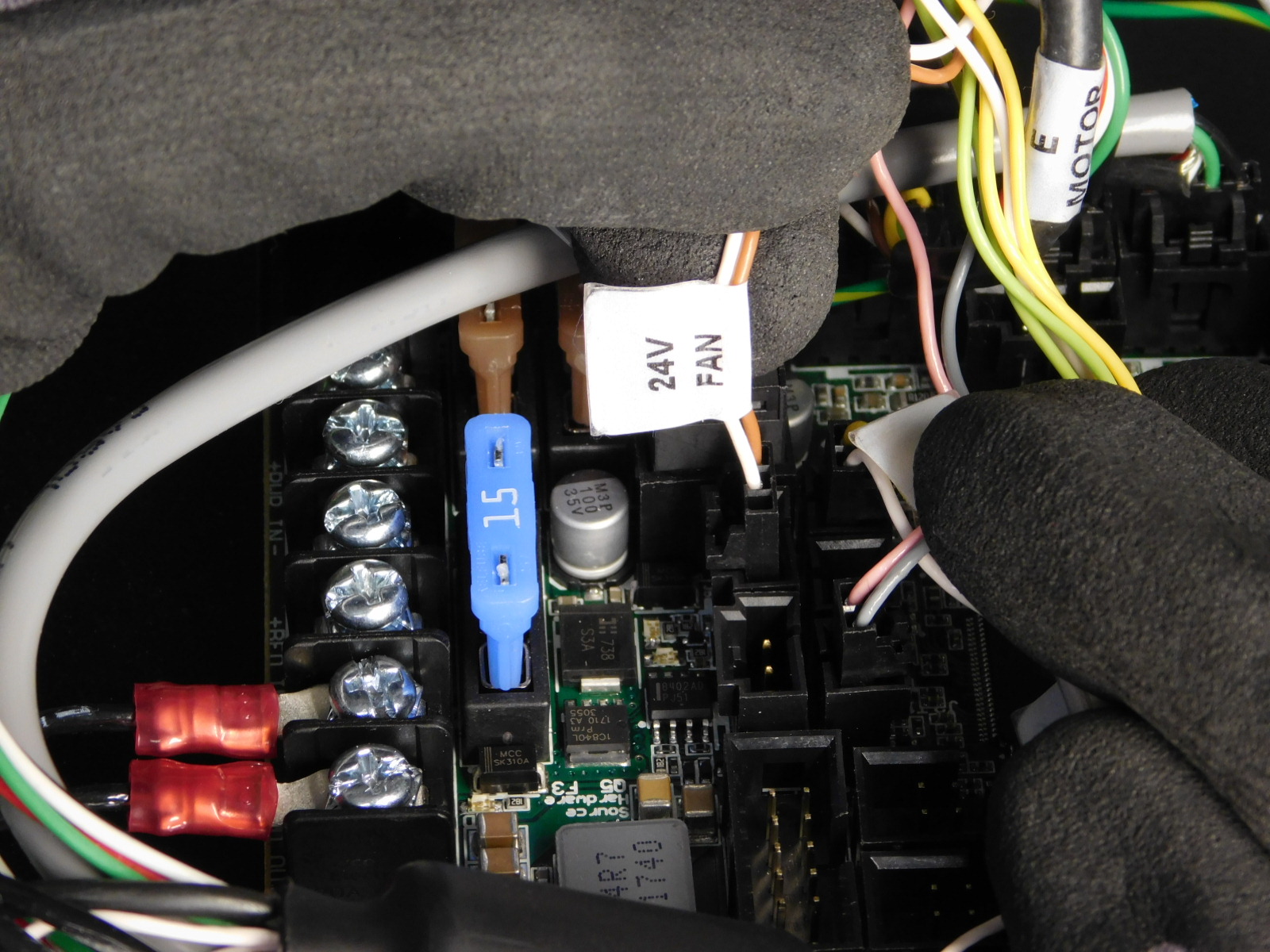
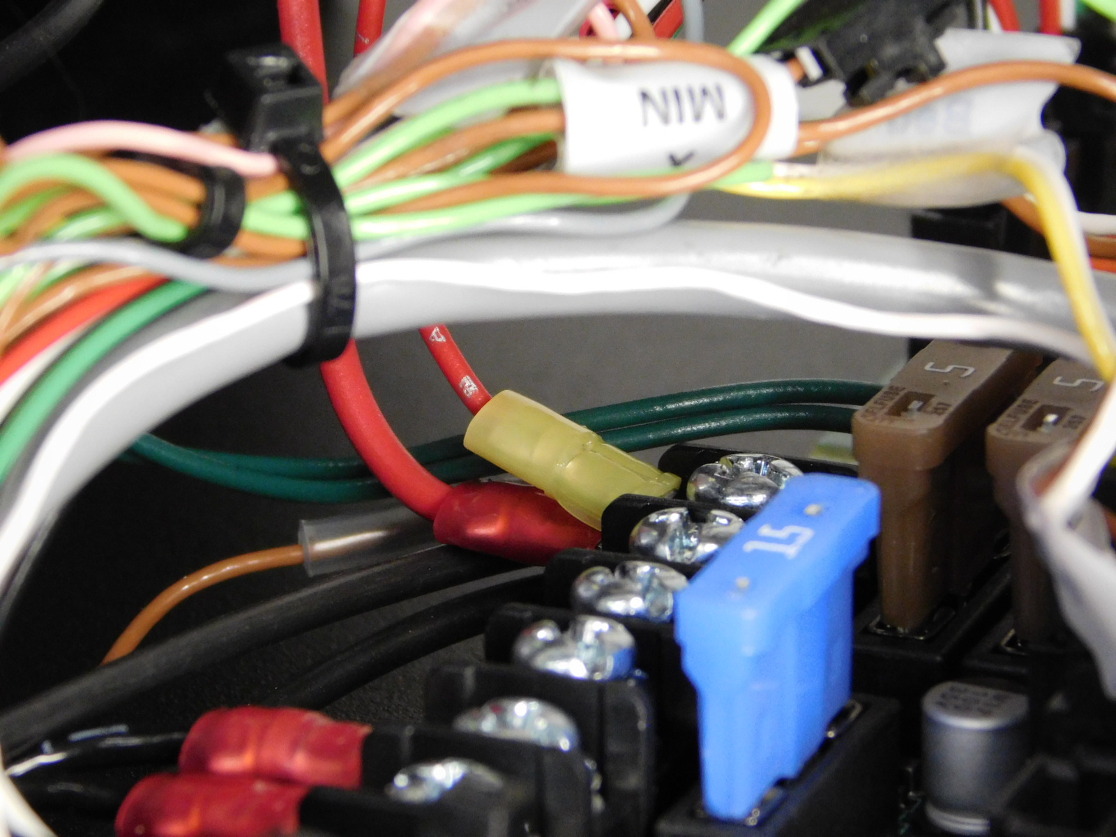
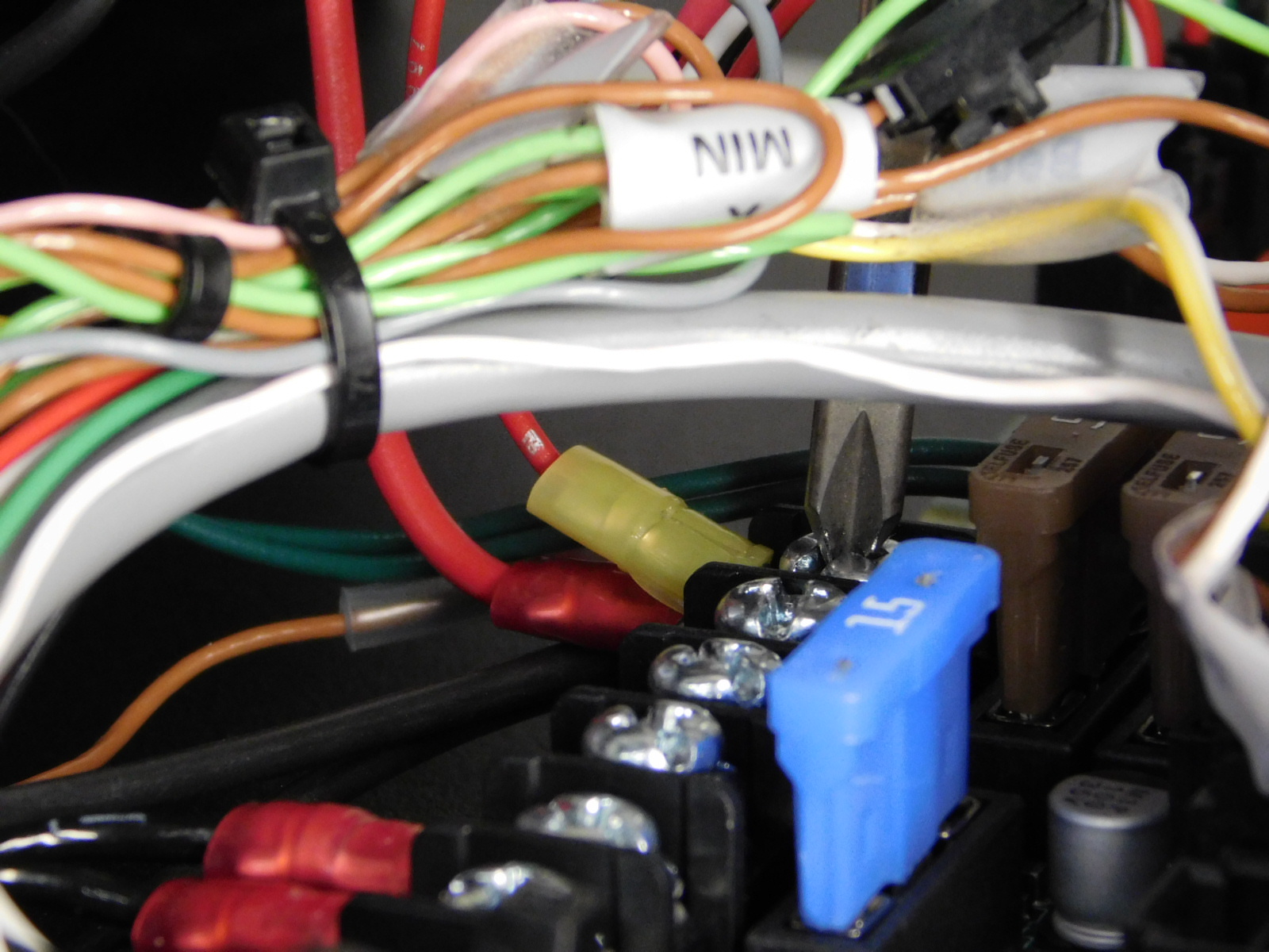
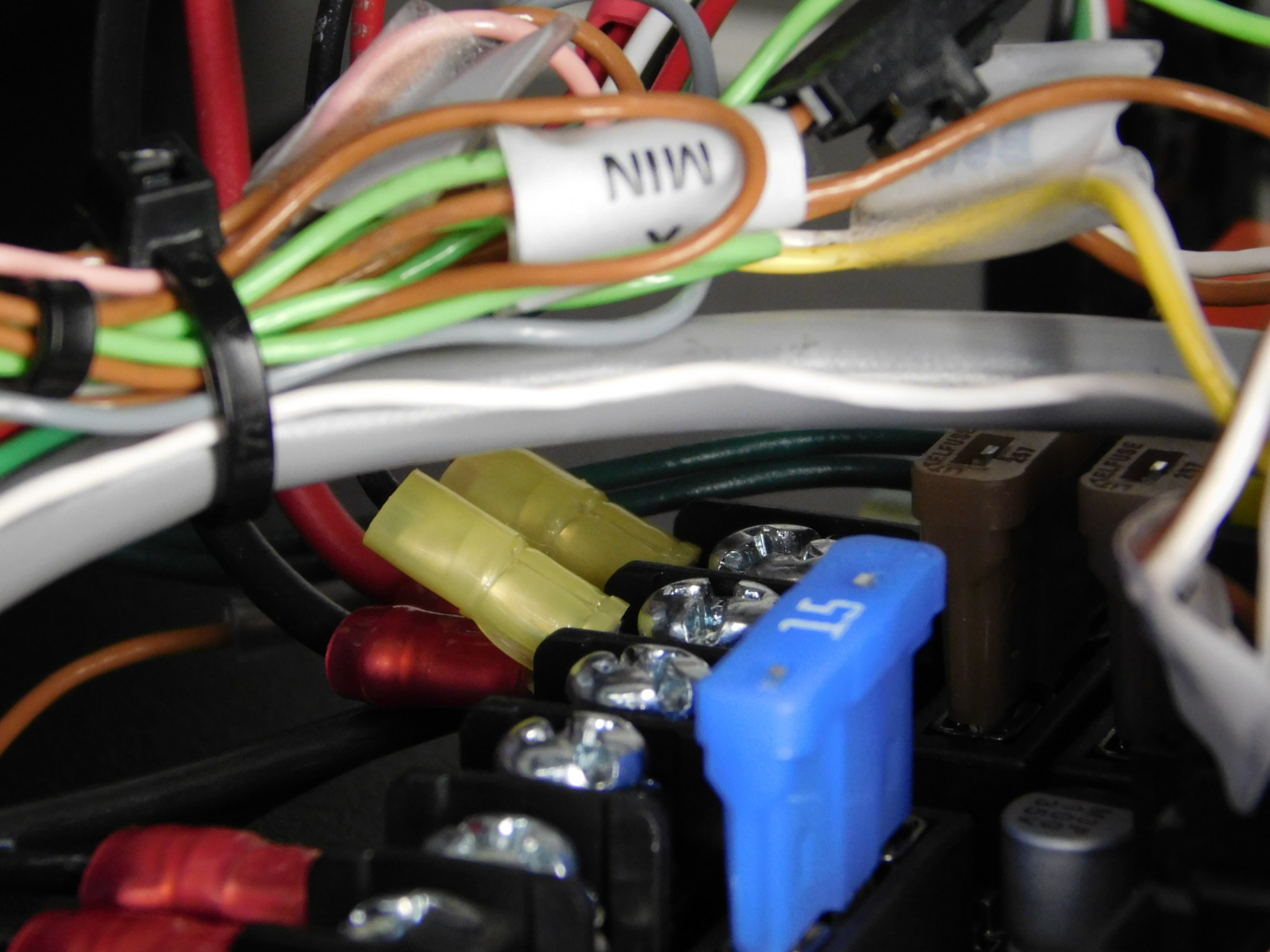
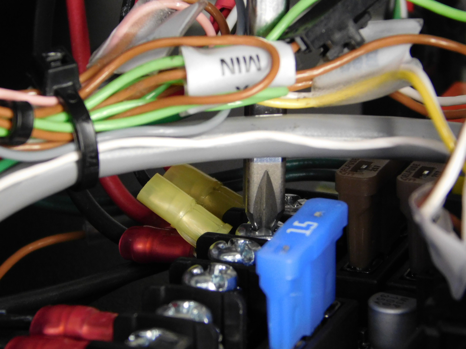
Locate the two red fork terminals labeled "Bed Pwr";
Using a Phillips screwdriver, loosen the lower two terminals on the EinsyRetro board
Insert the fork terminals into the two lower terminals (polarity irrelevant) and re-tighten the terminals securely using a Phillips screwdriver. Torque the terminals to 15 in*lbs.
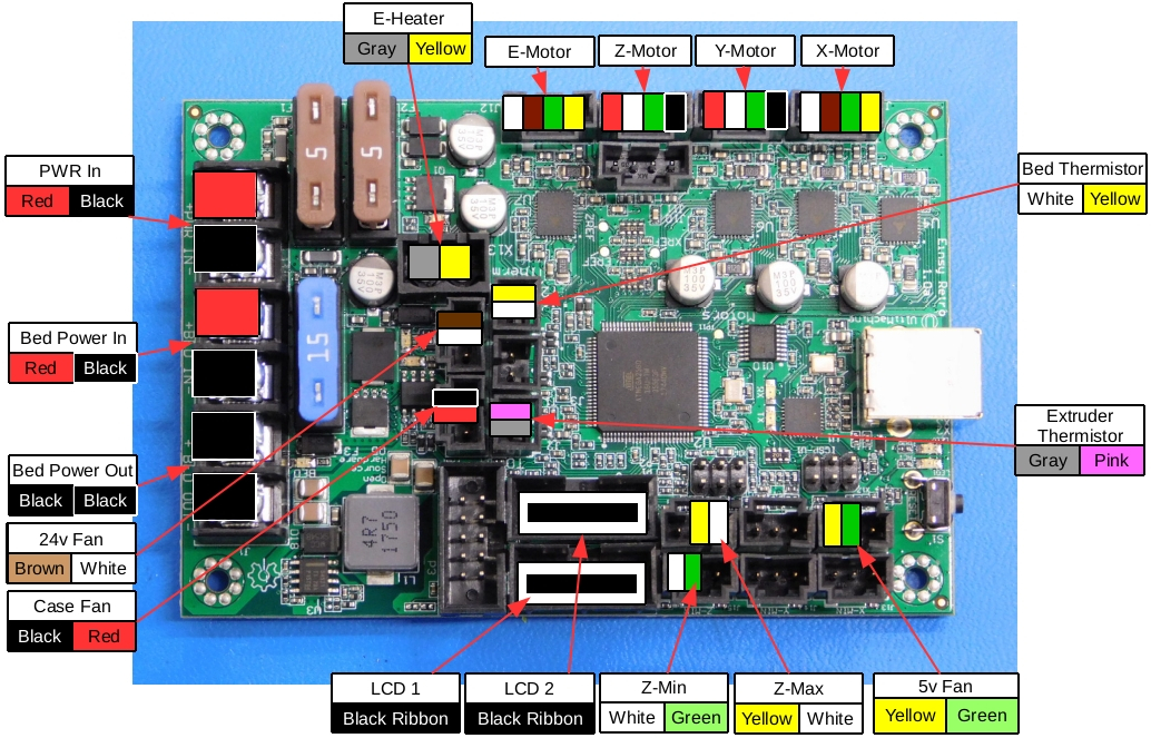
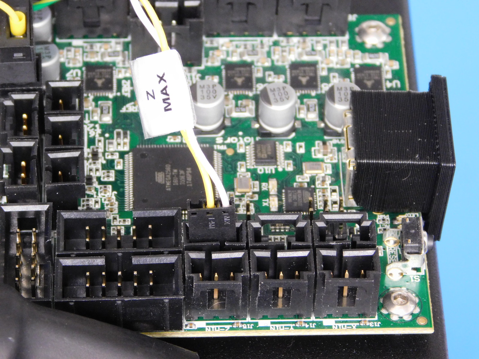
Locate the 3-pin Molex connector labeled "Z-Max" and connect to the board in the location shown.
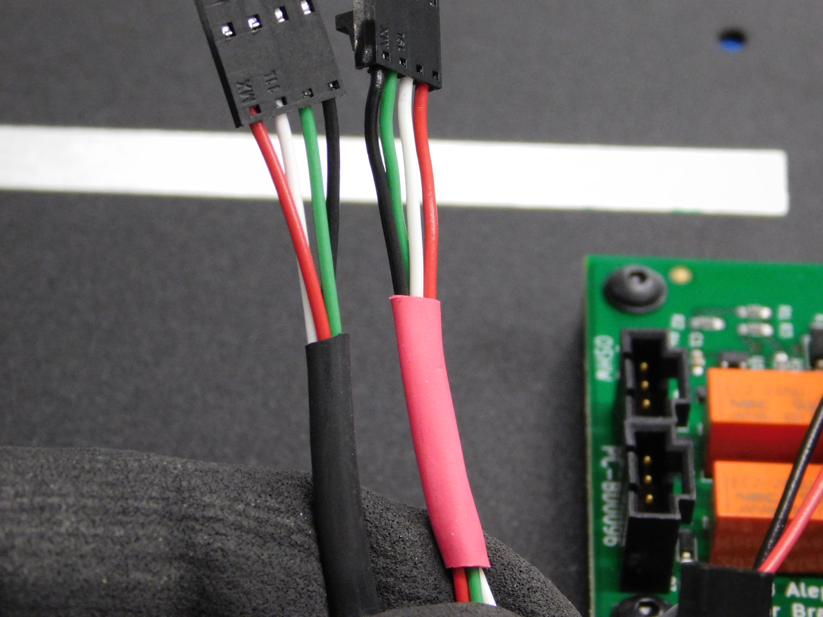
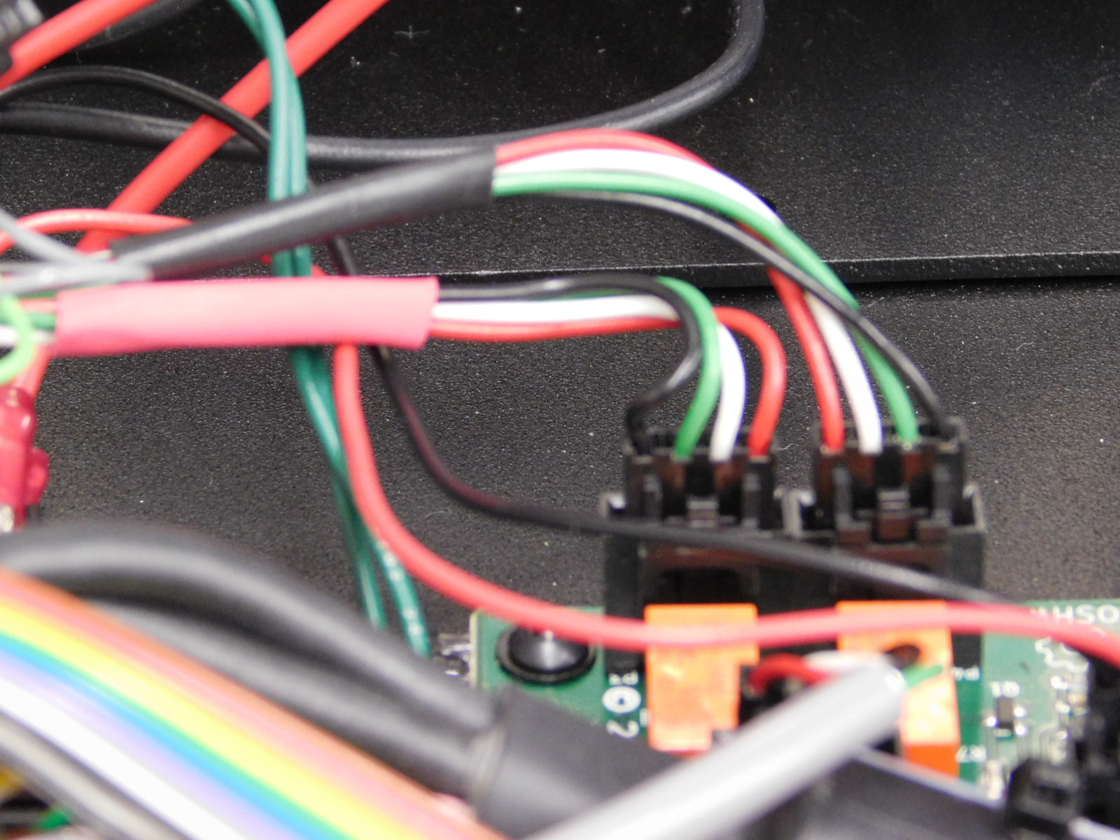
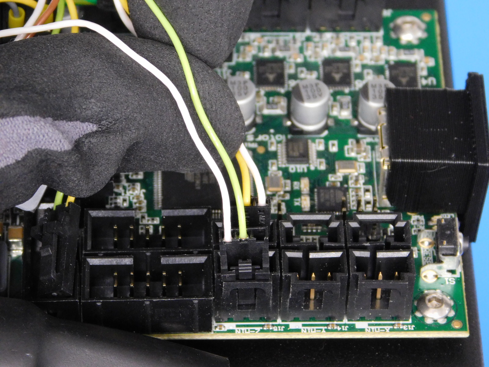
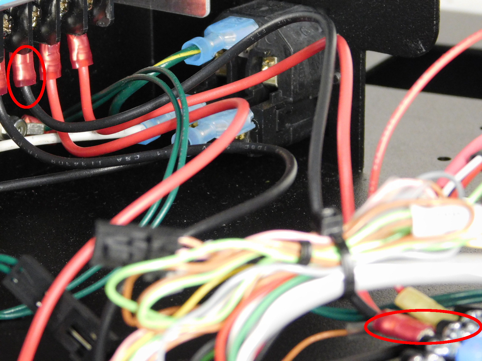
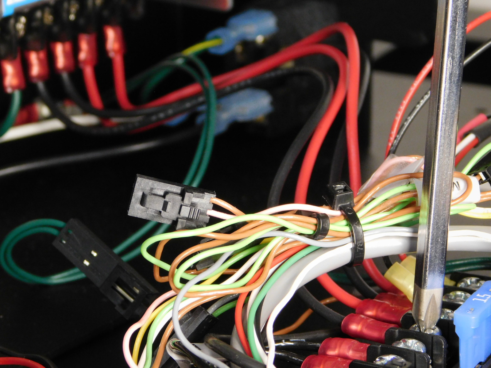
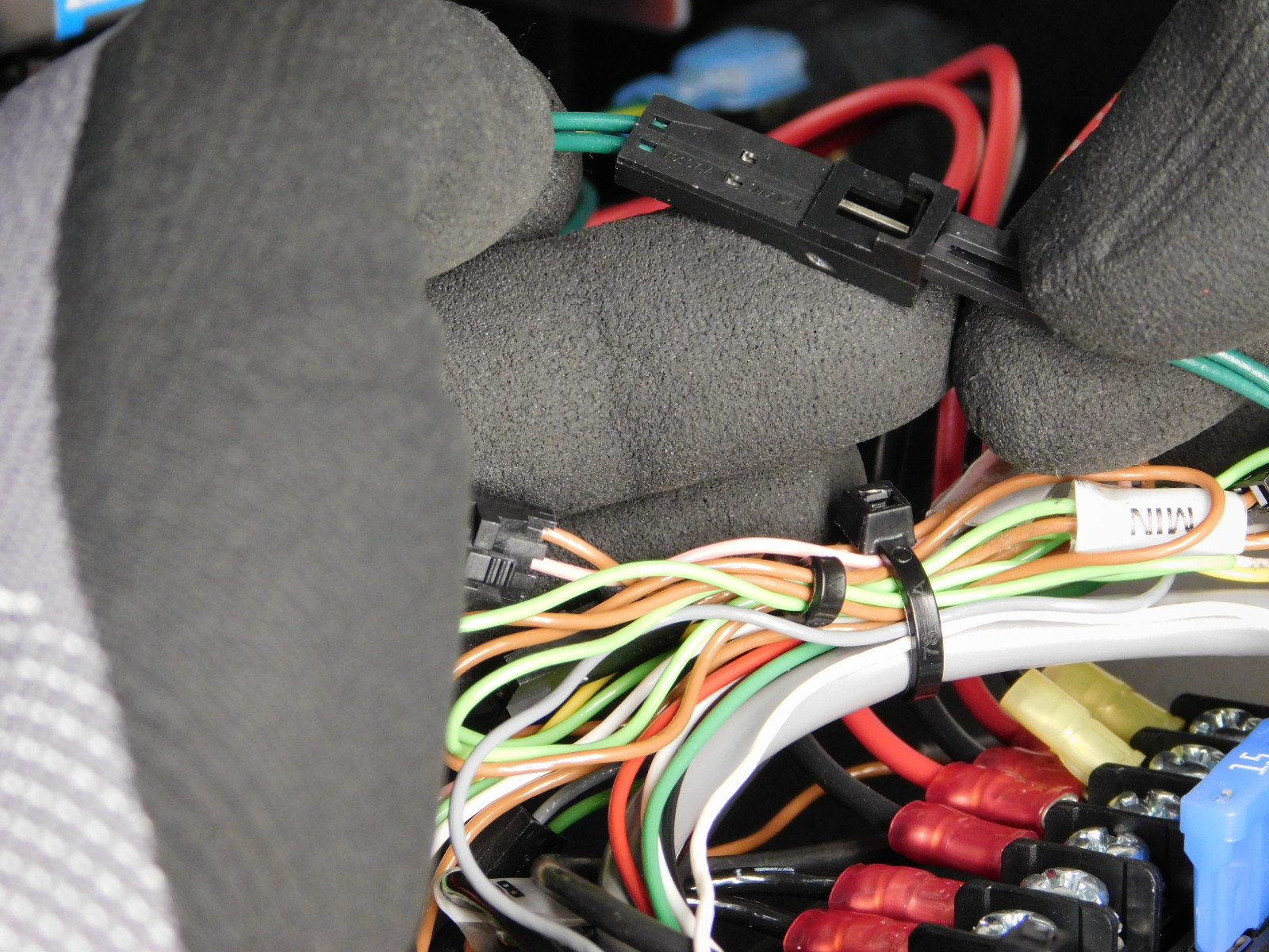
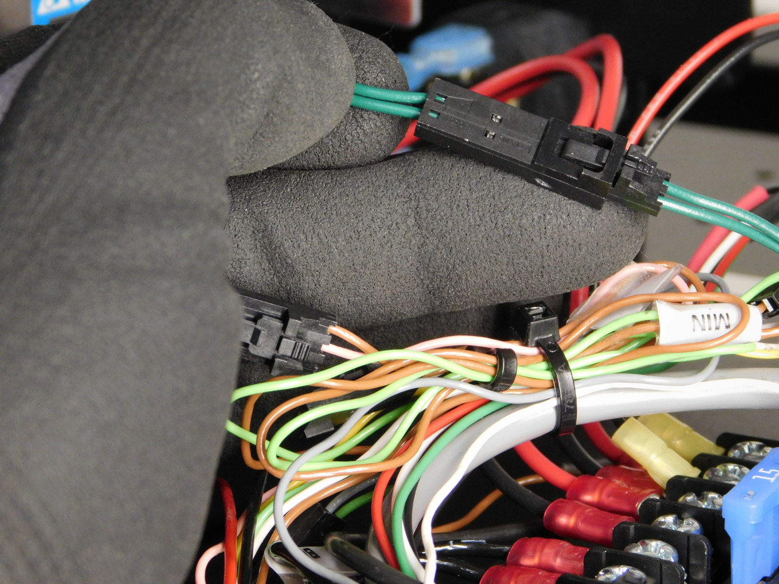
On the harness exiting the bottom of the left plate, locate the single white wire connected to pin 1 of a 3-pin Molex connector
On the harness exiting the left frame plate above the control board, locate the single un-pinned green wire and connect to pin 2 of the connector on the white wire you just located.
Now connect this to the Z-Min connector on the EinsyRetro board, as pictured.


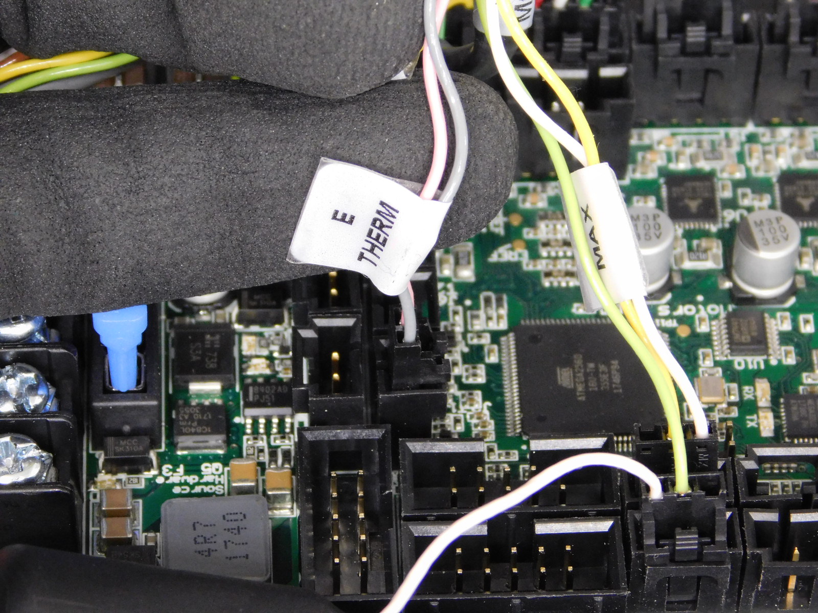
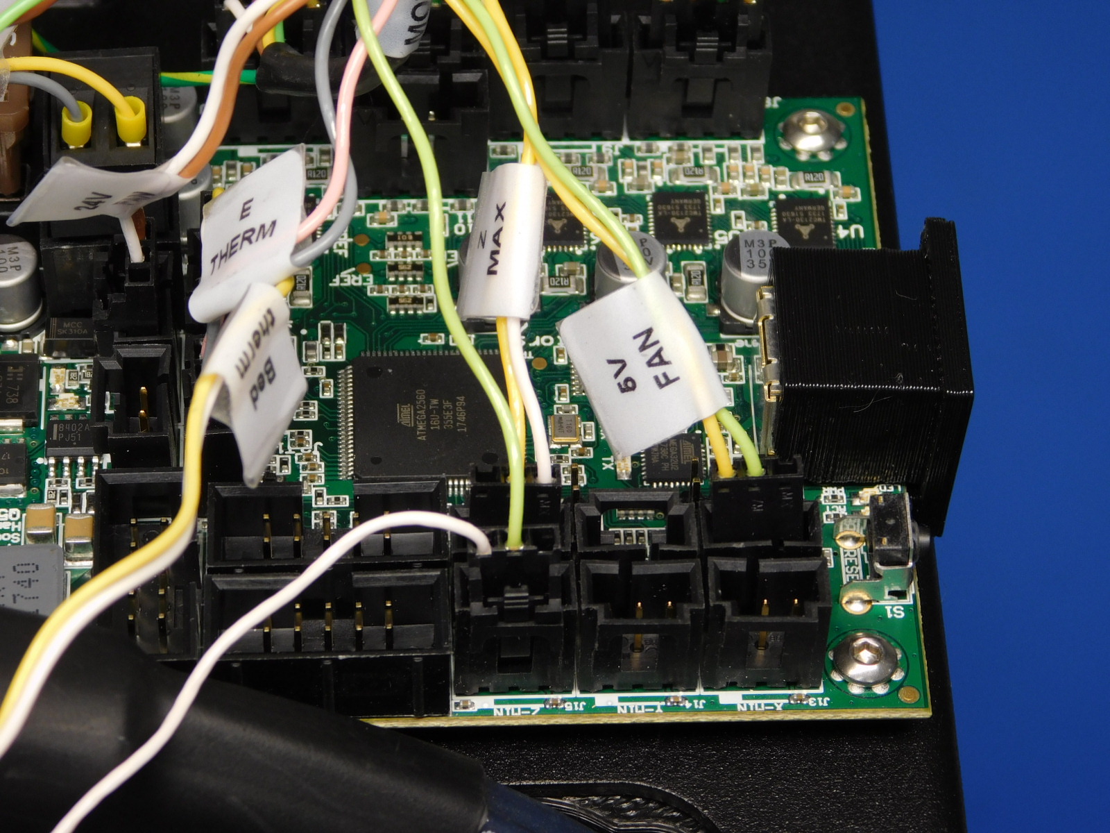
Locate the two pin Molex connector labeled “E Therm” and plug in as pictured.
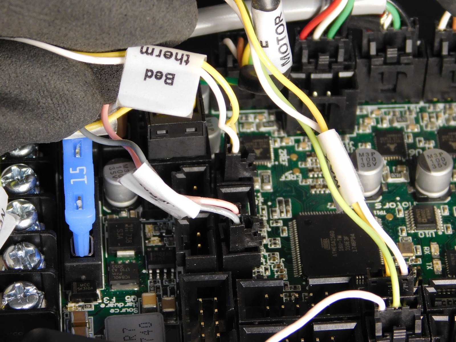
Locate the two pin Molex connector labeled “Bed Therm” and plug in as pictured.

Locate the three pin Molex connector labeled “24V Fan” and plug in as pictured.
Locate the three pin Molex connector labeled “5V Fan” and connect to the header labeled "X-Max" as pictured.

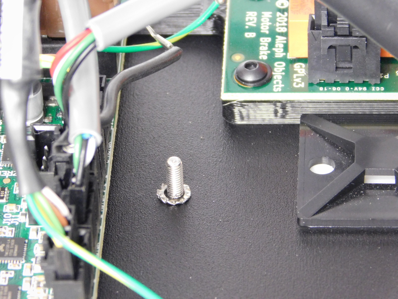
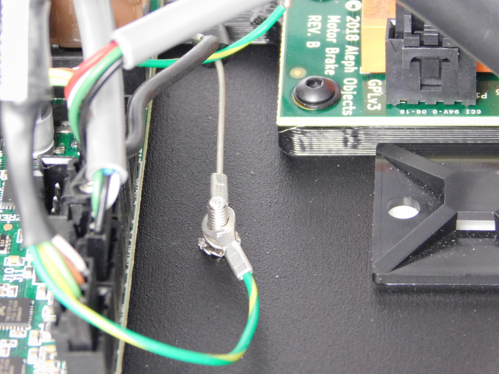
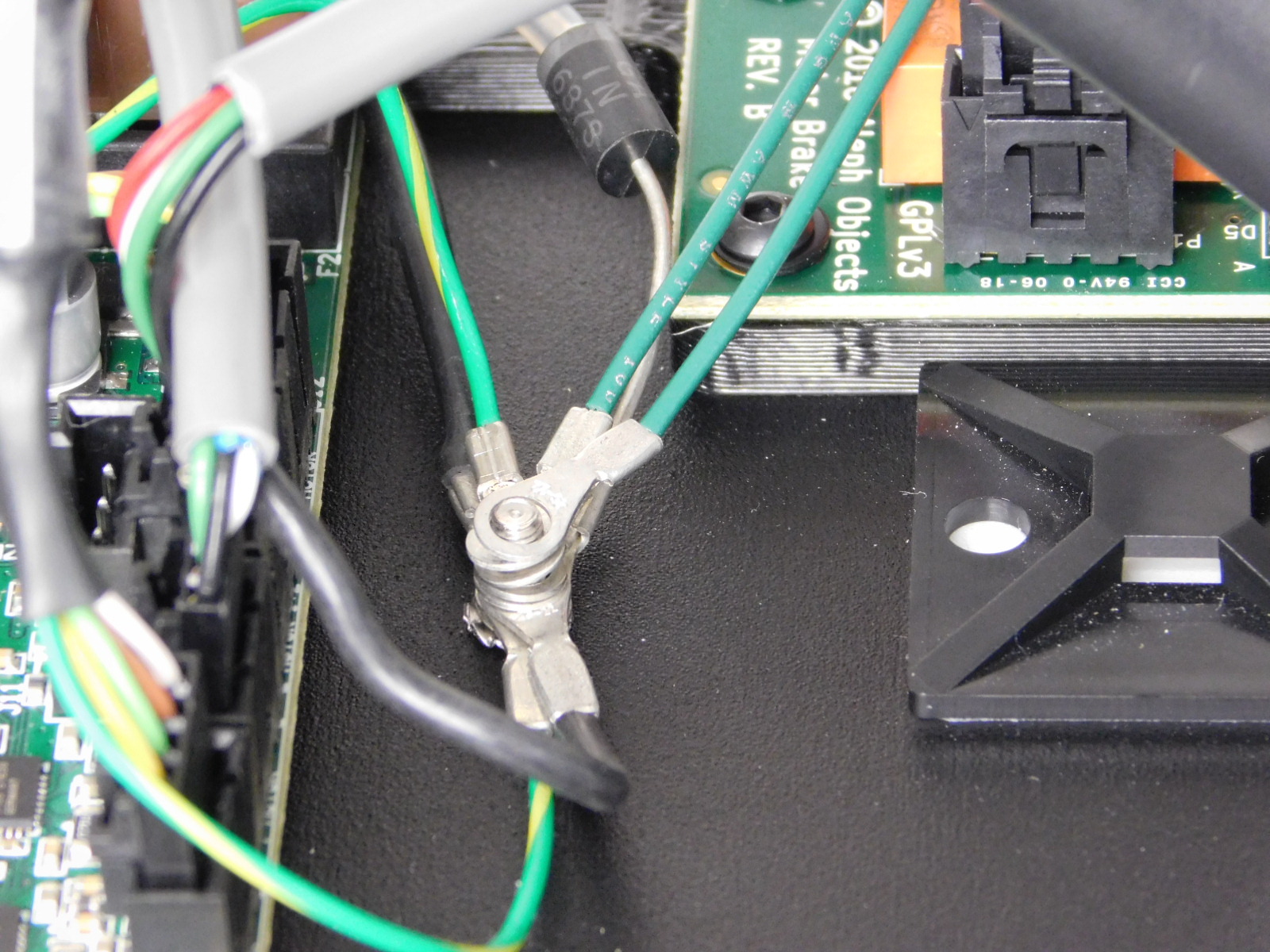
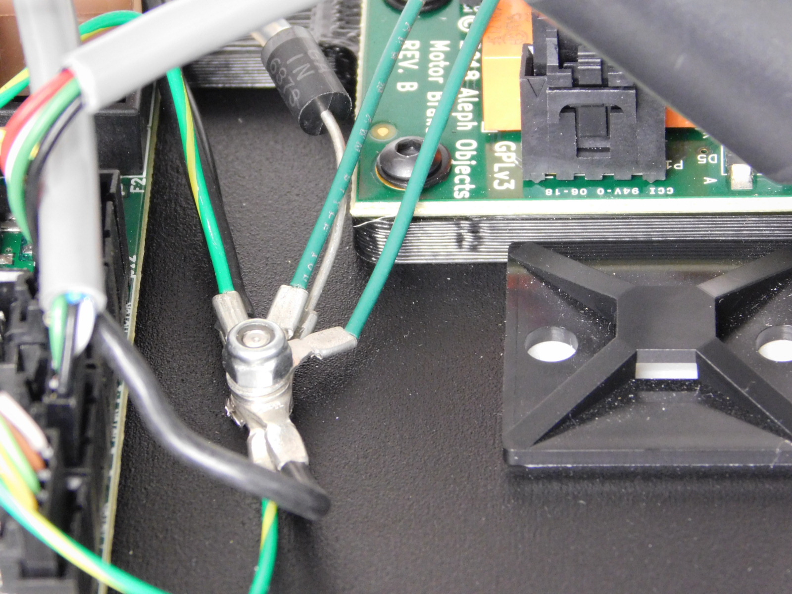
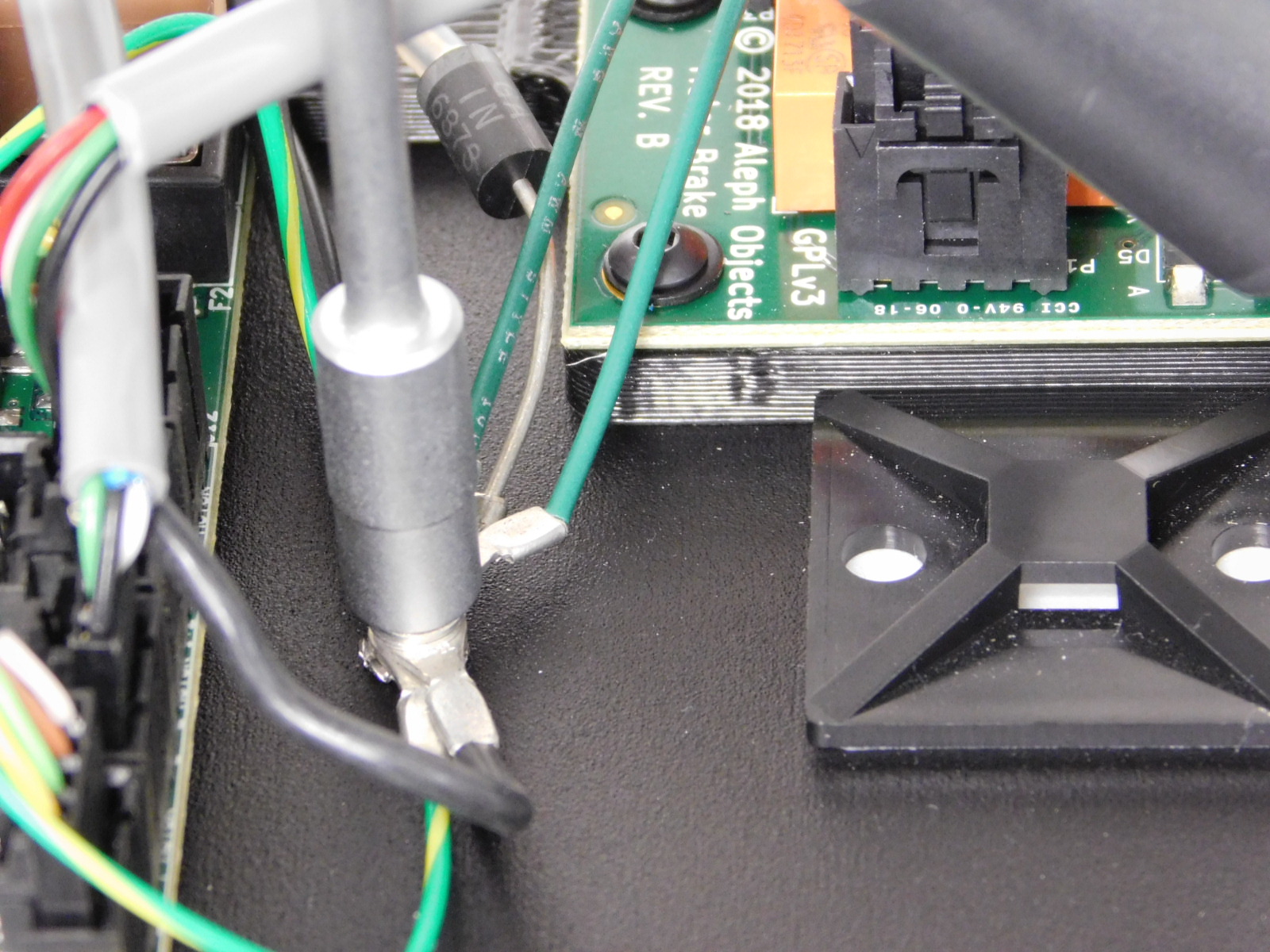
First put an M3 lock washer [HD-WA0035] onto the ground post on the left plate above the EinsyRetro control board.
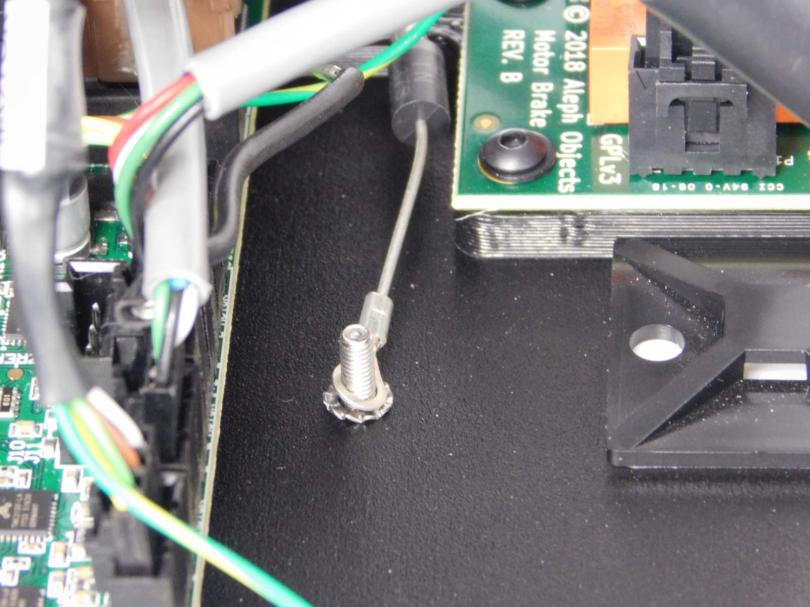
Next install the ring terminal of the TVS Diode wire onto the ground post.
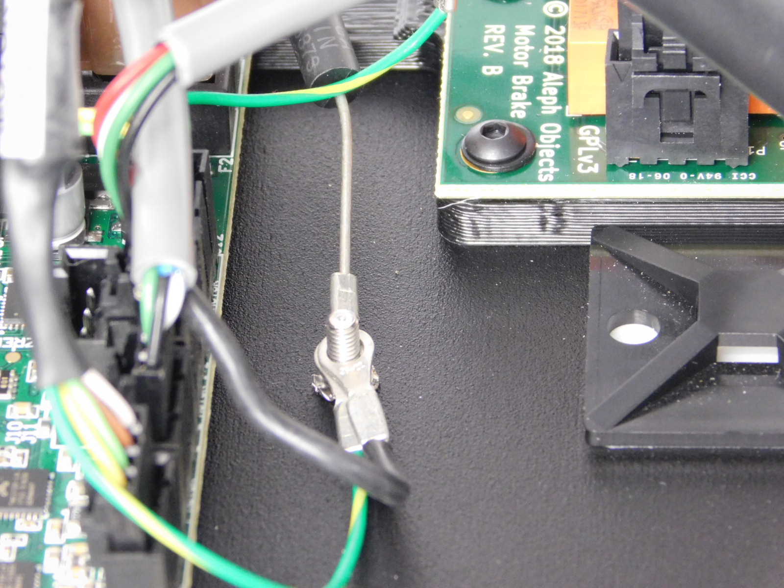
Install the ring terminal of the X motor ground wire onto the ground post.
Install the ring terminal of the Y motor ground wire onto the ground post.
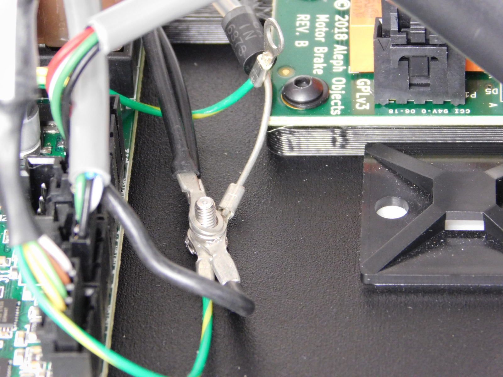
Install the 2 ring terminals of the Z motors ground wires onto the ground post.
Install the ring terminal of the Extruder motor ground wire onto the ground post.
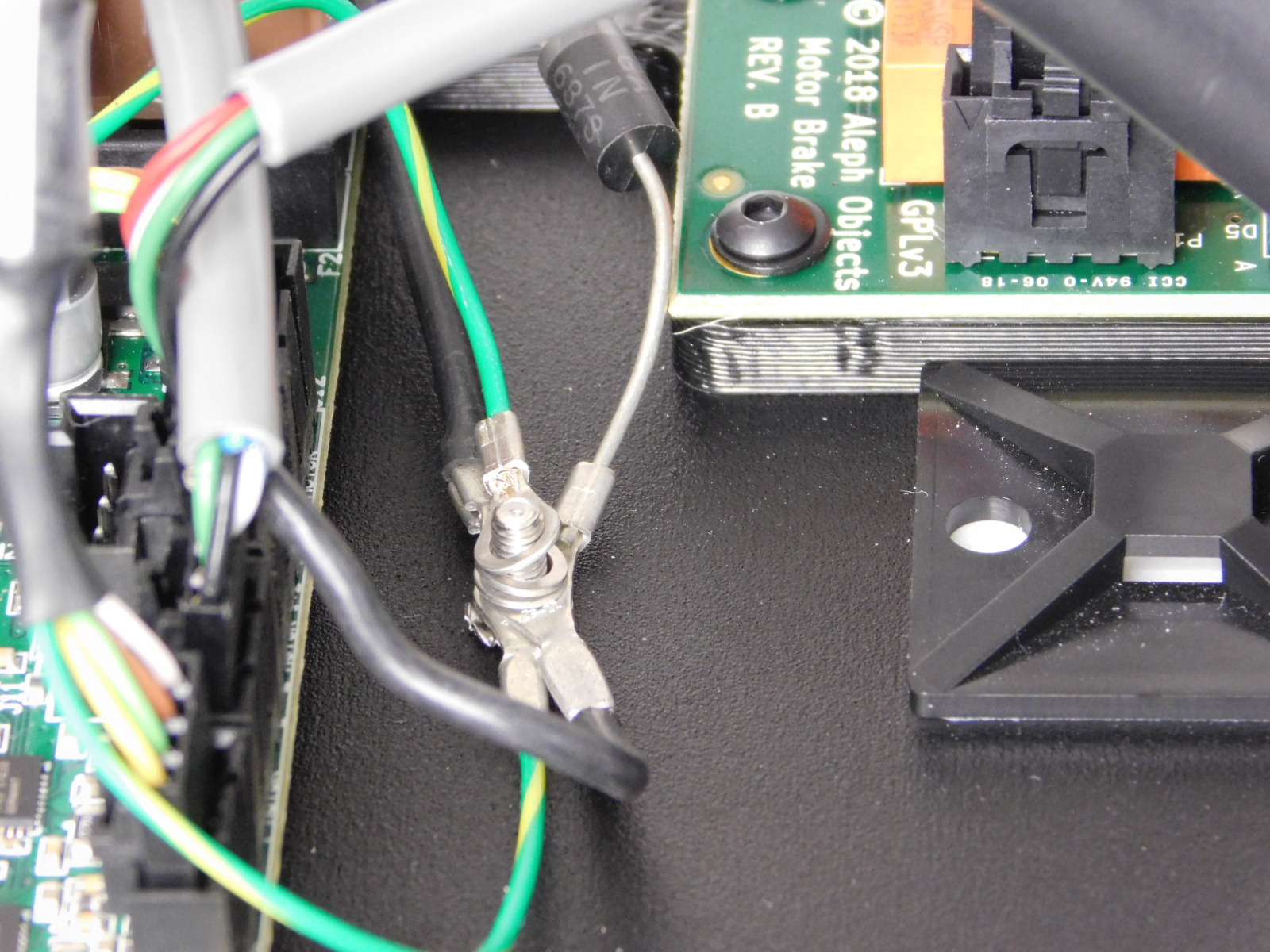
Install the 2 ring terminals of the Chassis Ground Extension [AS-CB0082] onto the ground post.
Use a 5.5mm nut driver and an M3 Nyloc Nut [HD-NT0001] to fasten all of these wires onto the ground post.
Tighten nut until the ring terminals can no longer move.
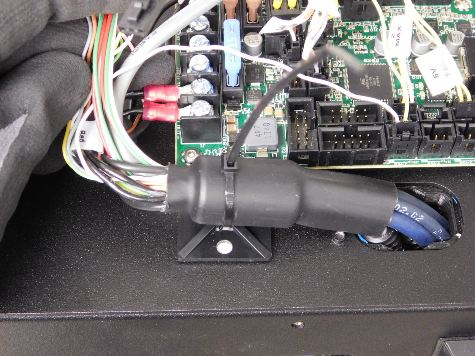
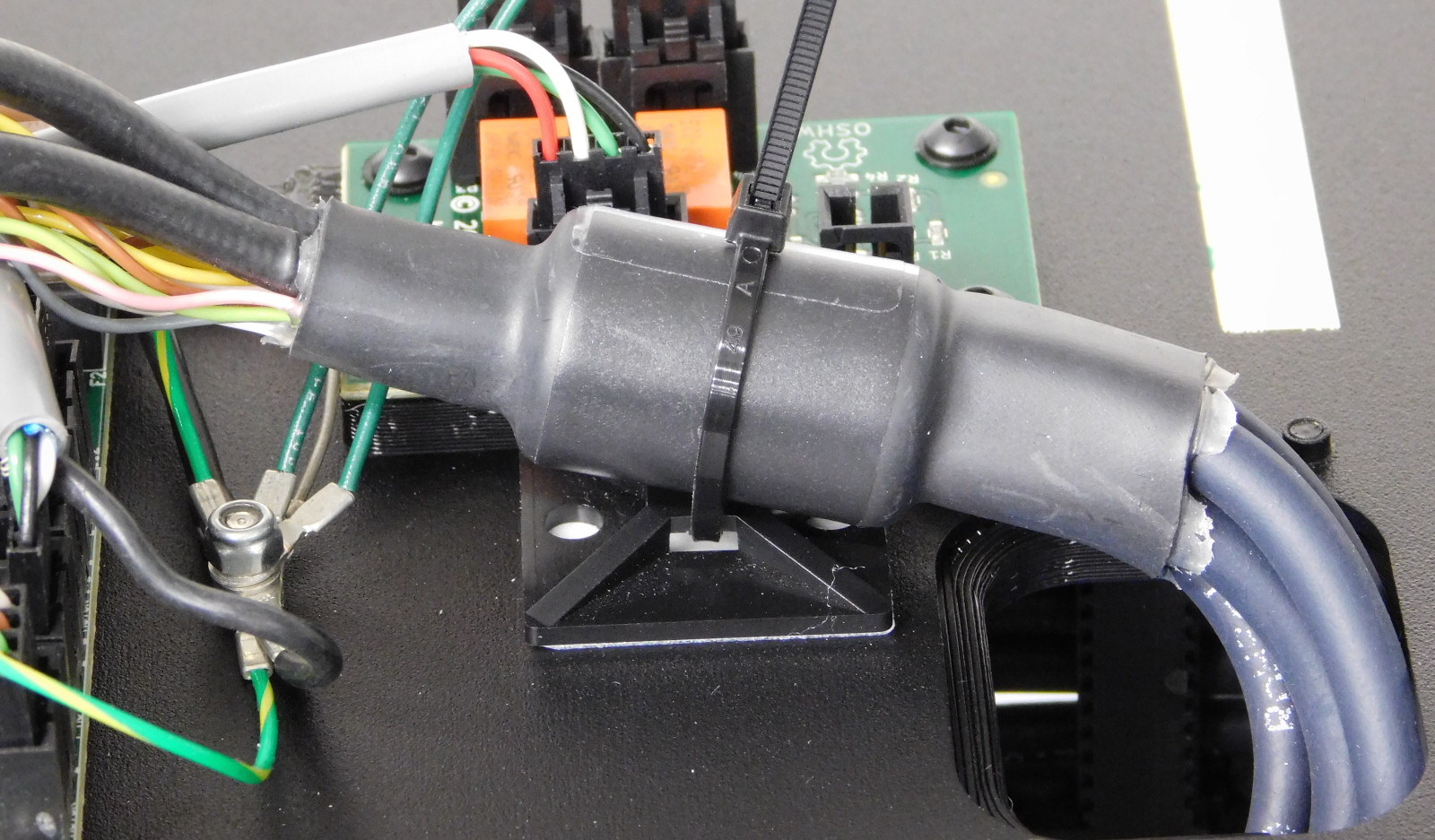
Secure the lower ferrite (YZ Harness) to the cable tie down below the EinsyRetro as pictured
Secure the upper ferrite (X/Extruder Harness) to the cable tie down next to the Z-Brake as pictured.
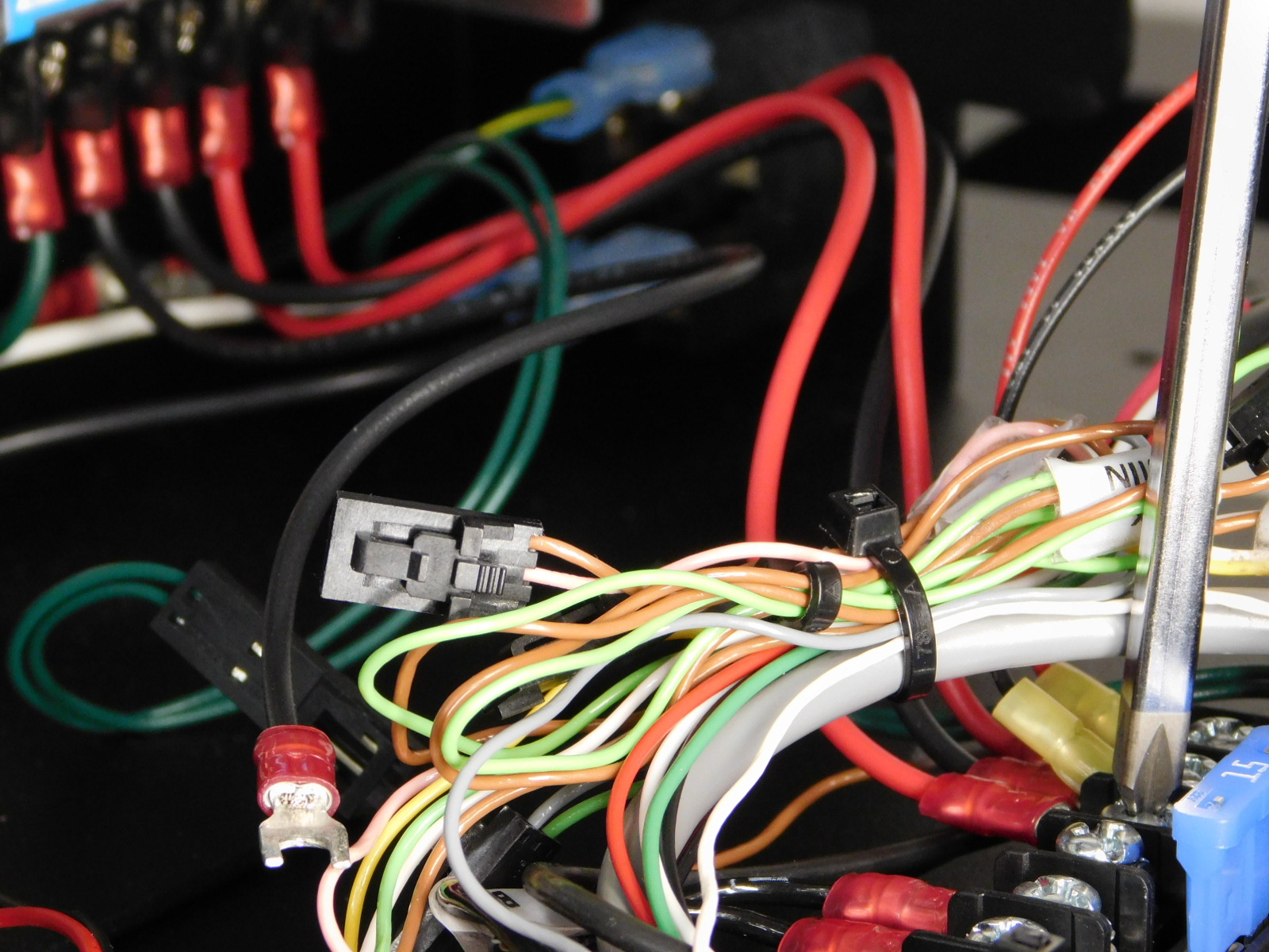
Locate the X-Min wire bundle;
Bundle the X-Min loop with the other un-used connectors
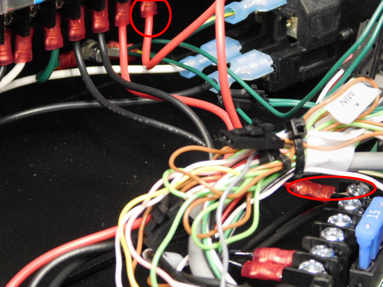
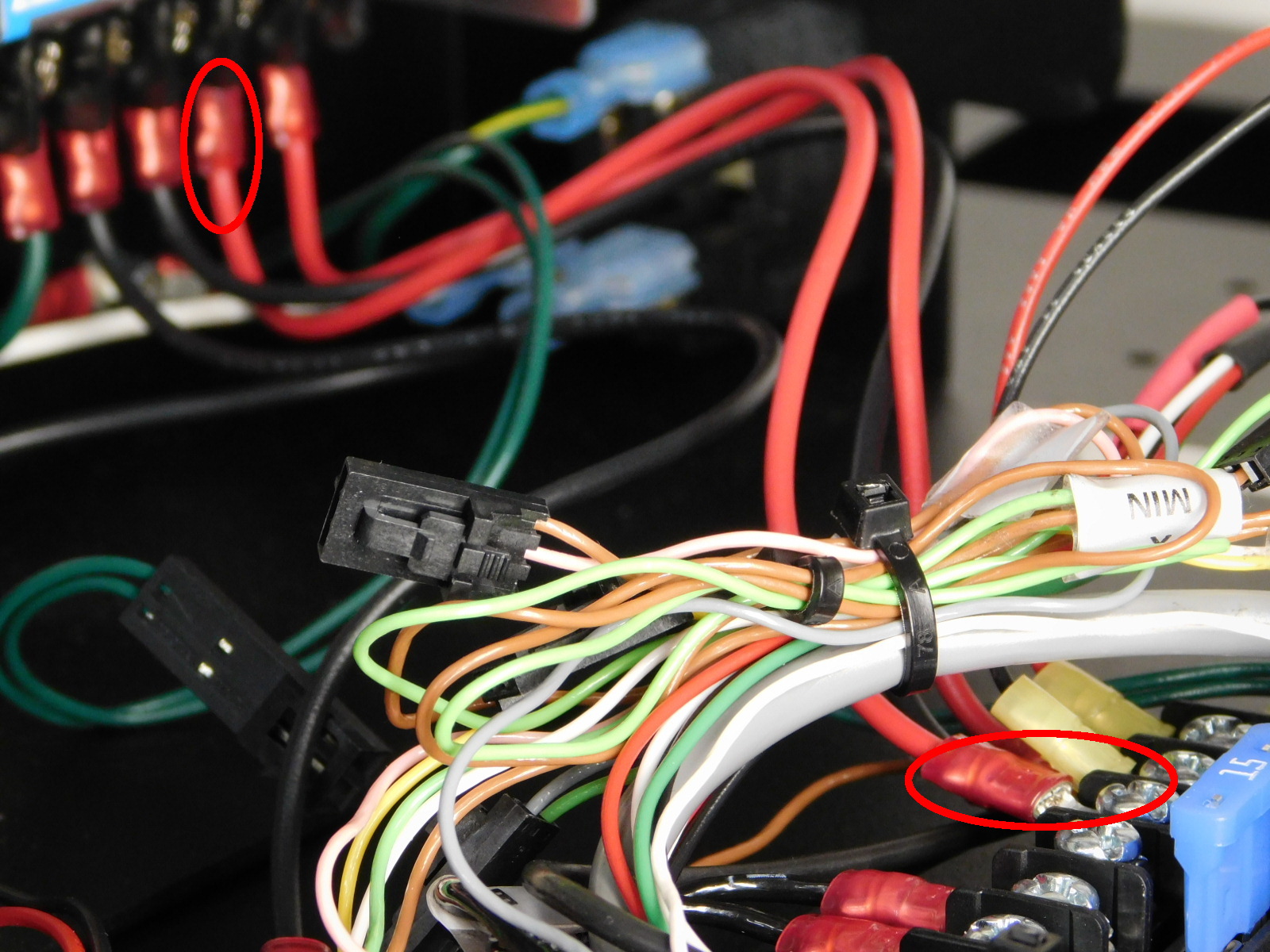
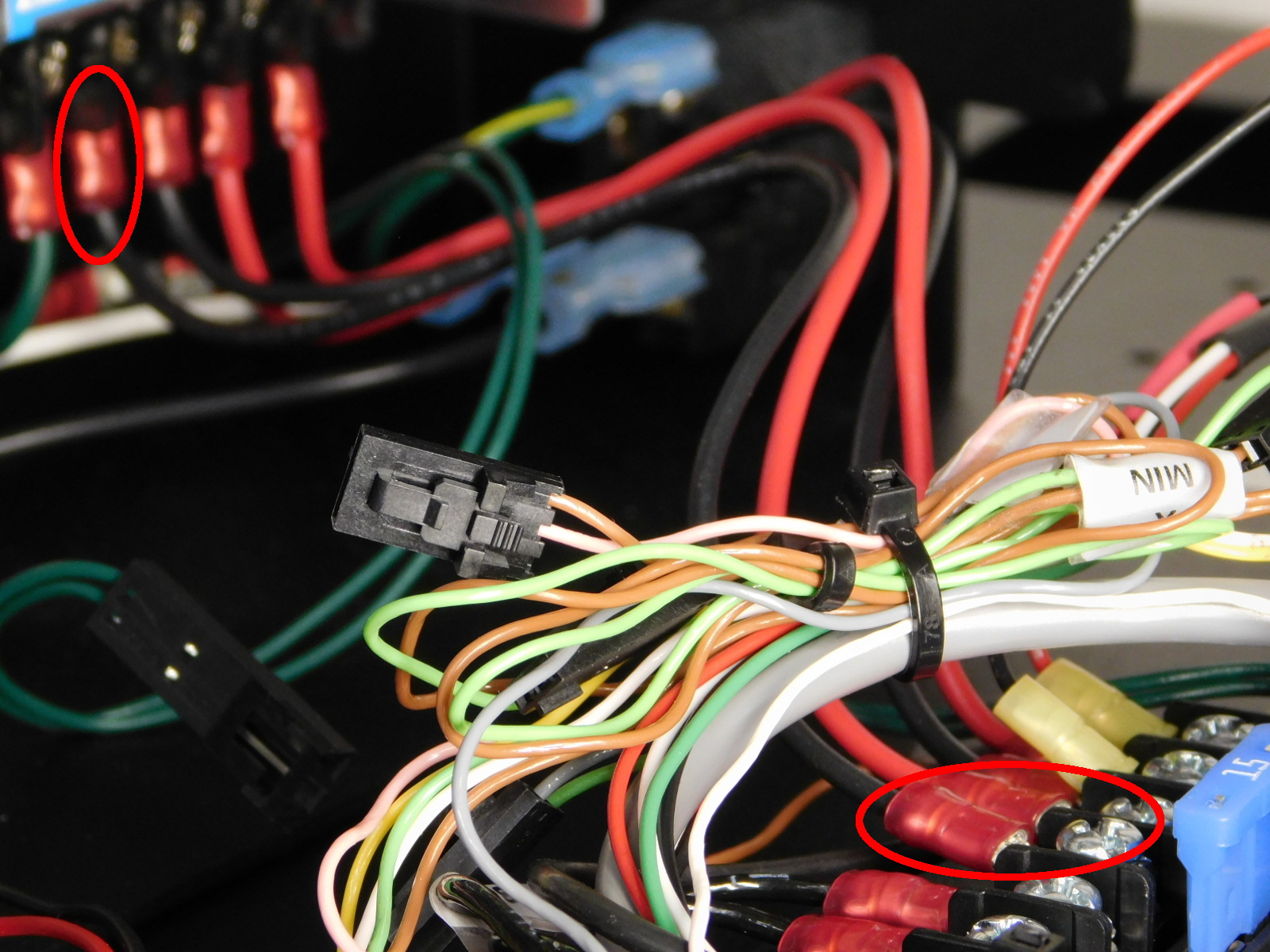
Route cables coming from the YZ harness away from the regulator (red square in picture) and include the Extruder heater in the cable tie.
Exclude the bed heater, the diode and both Z grounds from the cable tie.
Secure the cable tie around the listed wires approximately where shown to keep wires from gathering above the voltage regulator area.
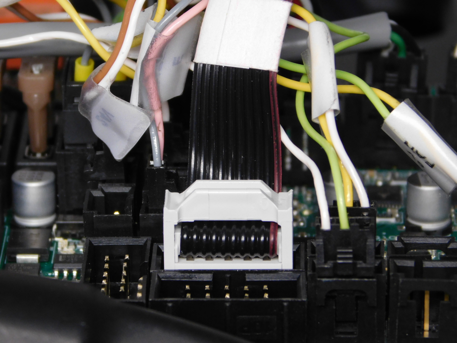
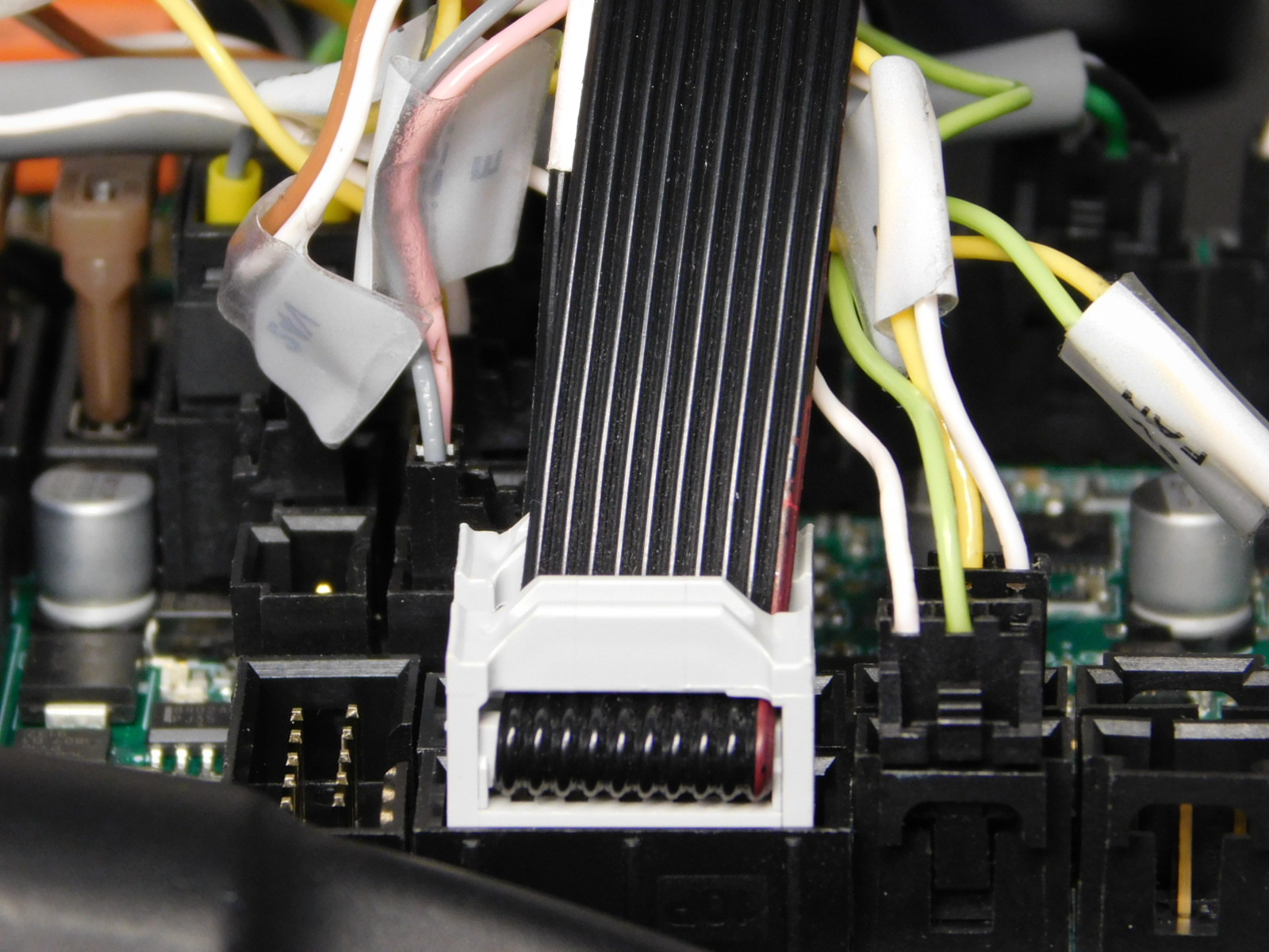
With the end of the cable that has the wire facing the keyed side of the connector, connect LCD Harness 2 [AS-CB0084] to P2 Header on the EinsyRetro as pictured.
With the end of the cable that has the wire facing the keyed side of the connector, connect LCD Harness 1 [AS-CB0083] to P1 Header on the EinsyRetro as pictured.
Route the two harnesses through the upper strain relief of the left plate, above the blue wires.

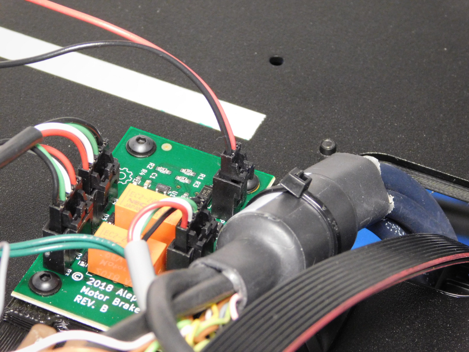
Connect the 2-pin molex end of the Z-Brake Power harness [AS-CB0069] to the 2-pin header on the Z-Brake as pictured.
Connect the power supply to the EinsyRetro as follows:
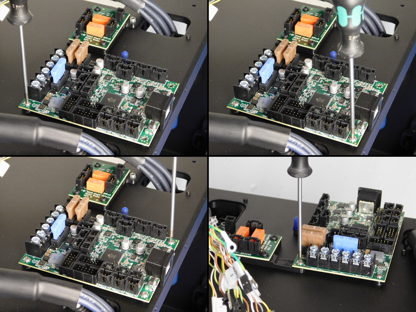
Connect the right-most red lead from the power supply to the top left terminal on the board by loosening the terminal screw with a Phillips screwdriver and inserting the fork terminal underneath as pictured.
Before tightening this terminal, insert the fork terminal of the Z-Brake power harness' red wire
Tighten securely. Torque to 15 in*lbs
Connect the right-most black lead from the power supply to the second terminal from the top, on the left side of the board by loosening the terminal screw with a Phillips screwdriver and inserting the fork terminal underneath as pictured.
Before tightening this terminal, insert the fork terminal of the Z-Brake power harness' black wire
Tighten securely. Torque to 15 in*lbs
Connect the red lead second from right on the power supply to the third terminal from the top on the left of the board by loosening the terminal screw with a Phillips screwdriver and inserting the fork terminal underneath as pictured.
Tighten securely. Torque to 15 in*lbs
Connect the black lead fourth from right on the power supply to the fourth terminal from the top on the left of the board by loosening the terminal screw with a Phillips screwdriver and inserting the fork terminal underneath as pictured.
Tighten securely. Torque to 15 in*lbs
Attach the Chassis to Ground Extension cable to the Earth Ground Extension cable. Click the 2 pin Molex connectors together. See picture.
Attach the Case fan wires (Red and Black wires with a three position connector) to the Einsy FAN1 header as pictured.


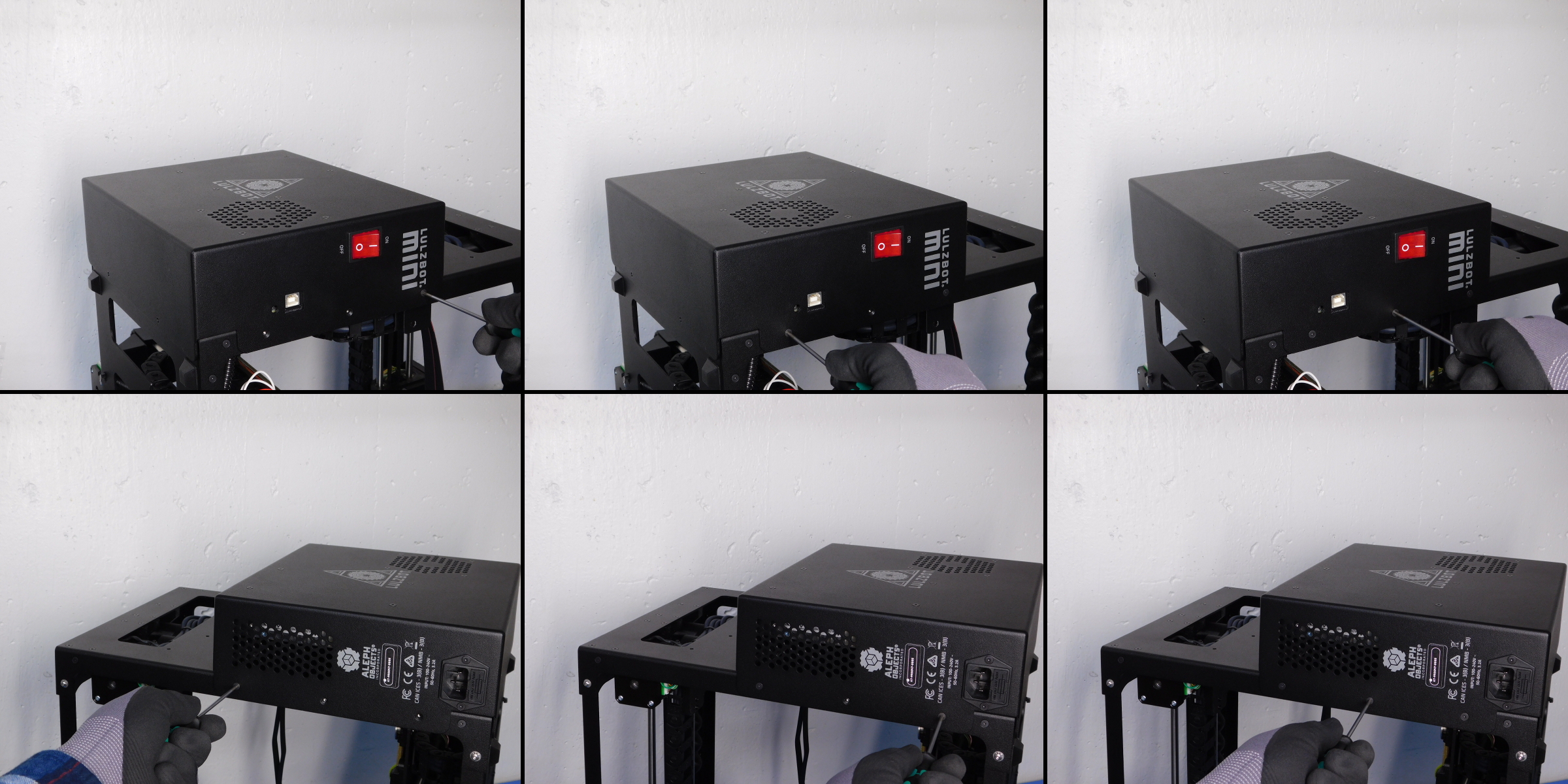
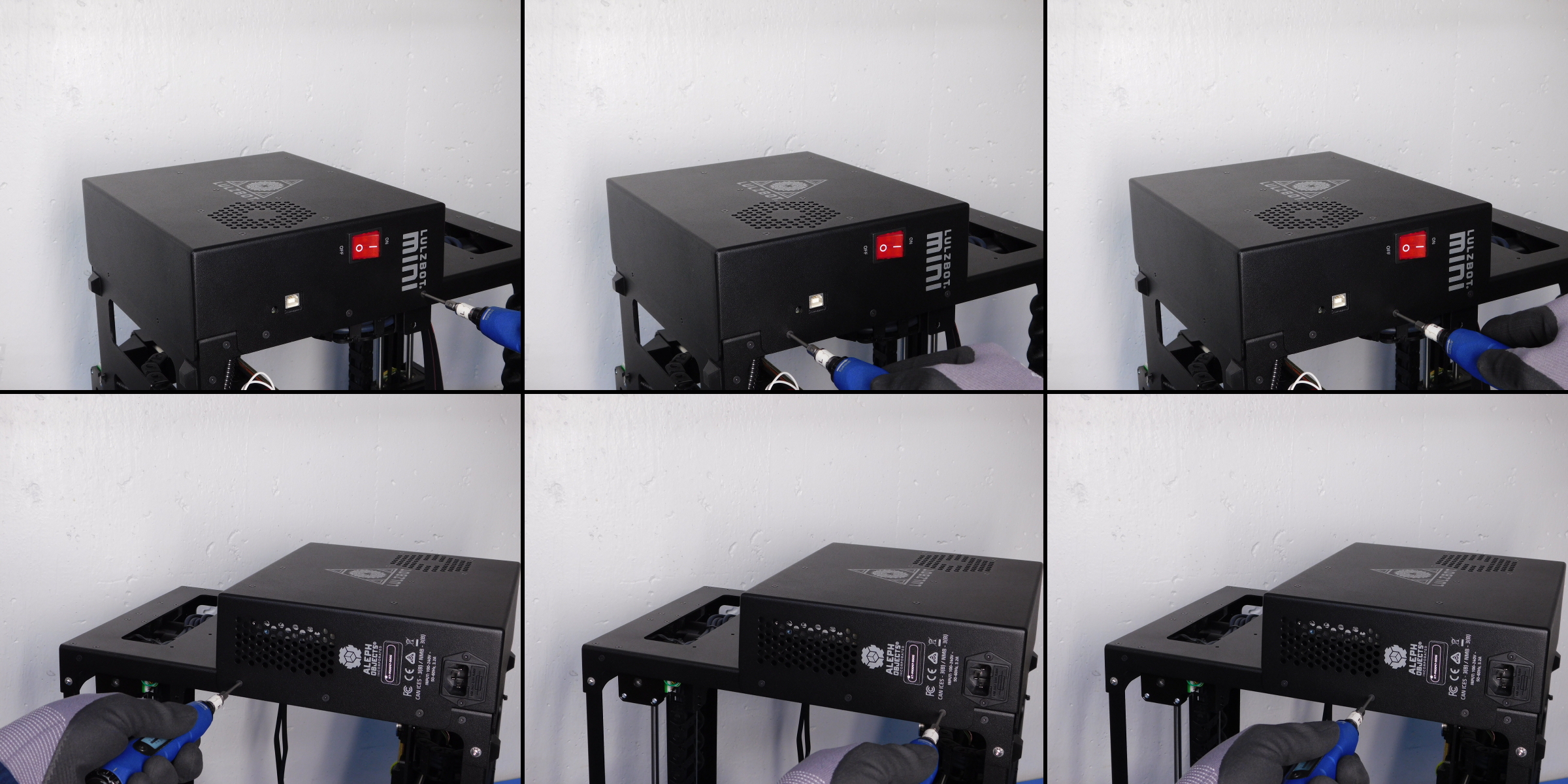
Attach the Electronics Case to the Mini left plate using six M3x6 FHCS to fasten the case to the left plate front and left plate back.
Torque to 5 in-lbs.
Secure on bottom of case using two M3x8 BHCS [HD-BT0137] with washers [HD-WA0038]
Torque to 5in*lbs
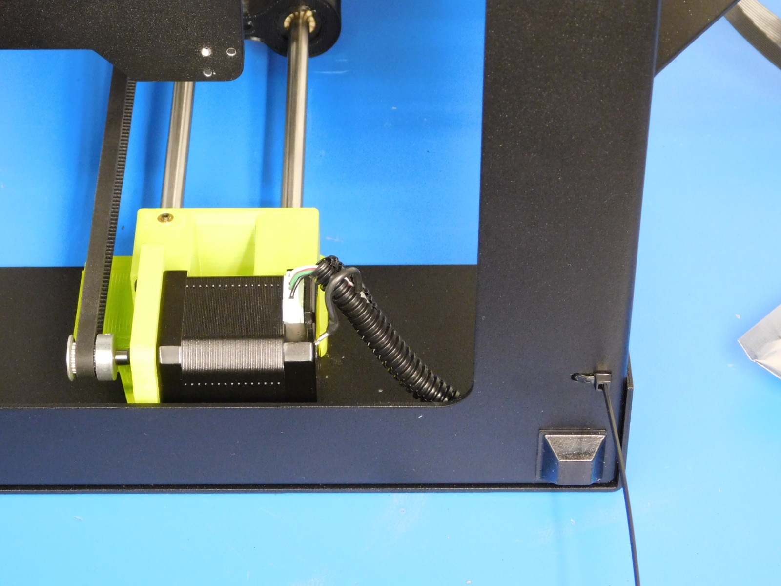
Secure the Z-Right Motor cable to the bottom frame plate at the location shown.
The latch should be on the bottom of the machine.
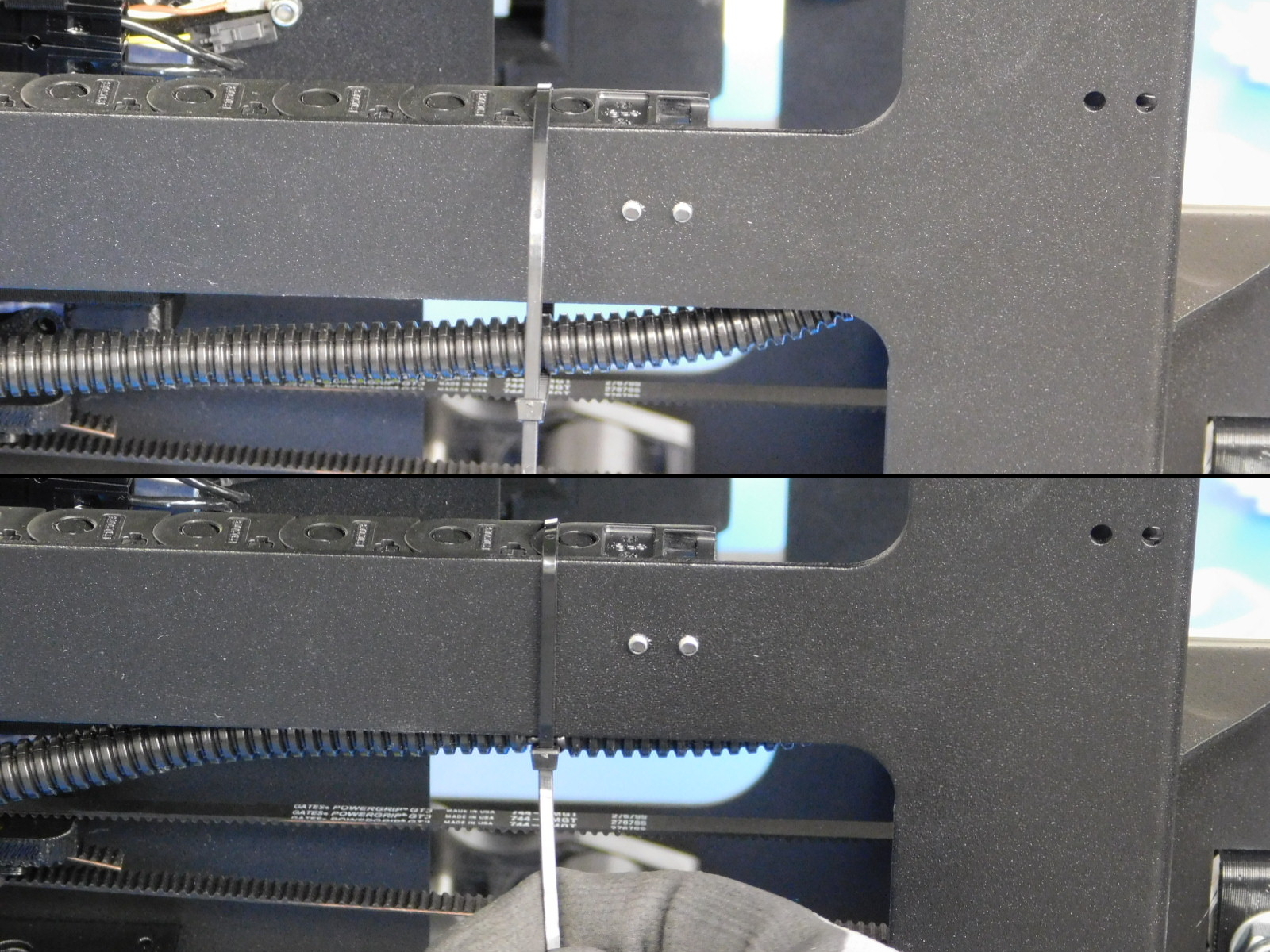
Secure the Y-Motor cable to the side of the cable chain as pictured.
Ensure cables inside the cable chain are not overlapping or twisted
Gather the Y axis cable harness (excluding Z-Left motor lead) and secure to the location shown, the zip tie latch should be on the bottom of the frame.
Ensure sufficient slack at the motor connections is given to prevent damage and accidental unplugging.
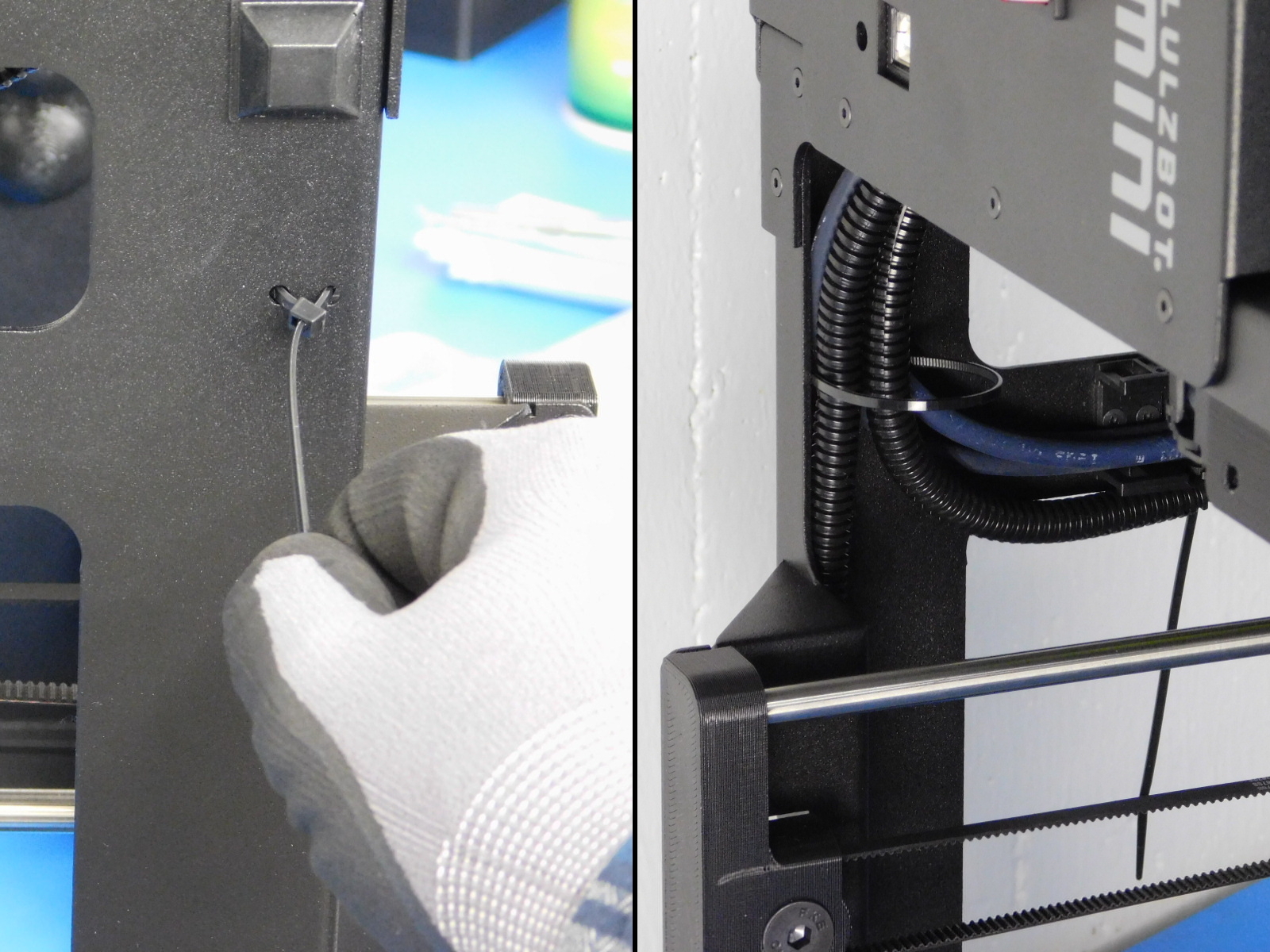
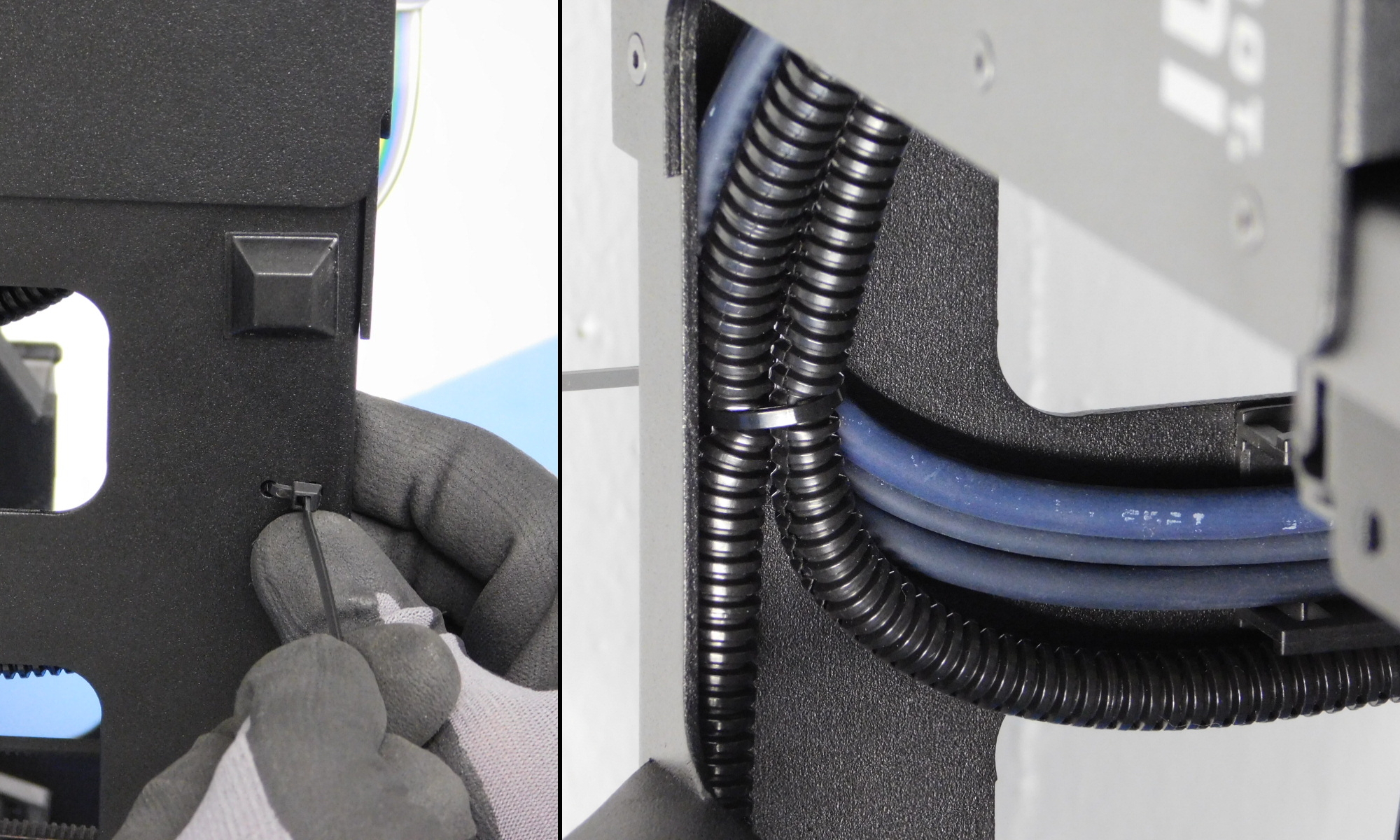
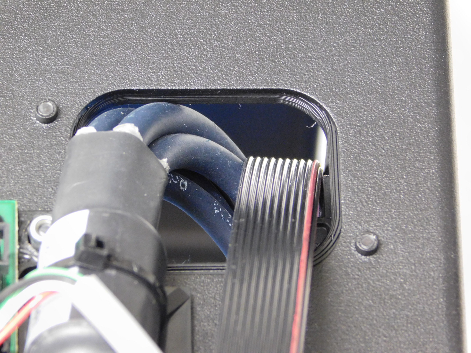
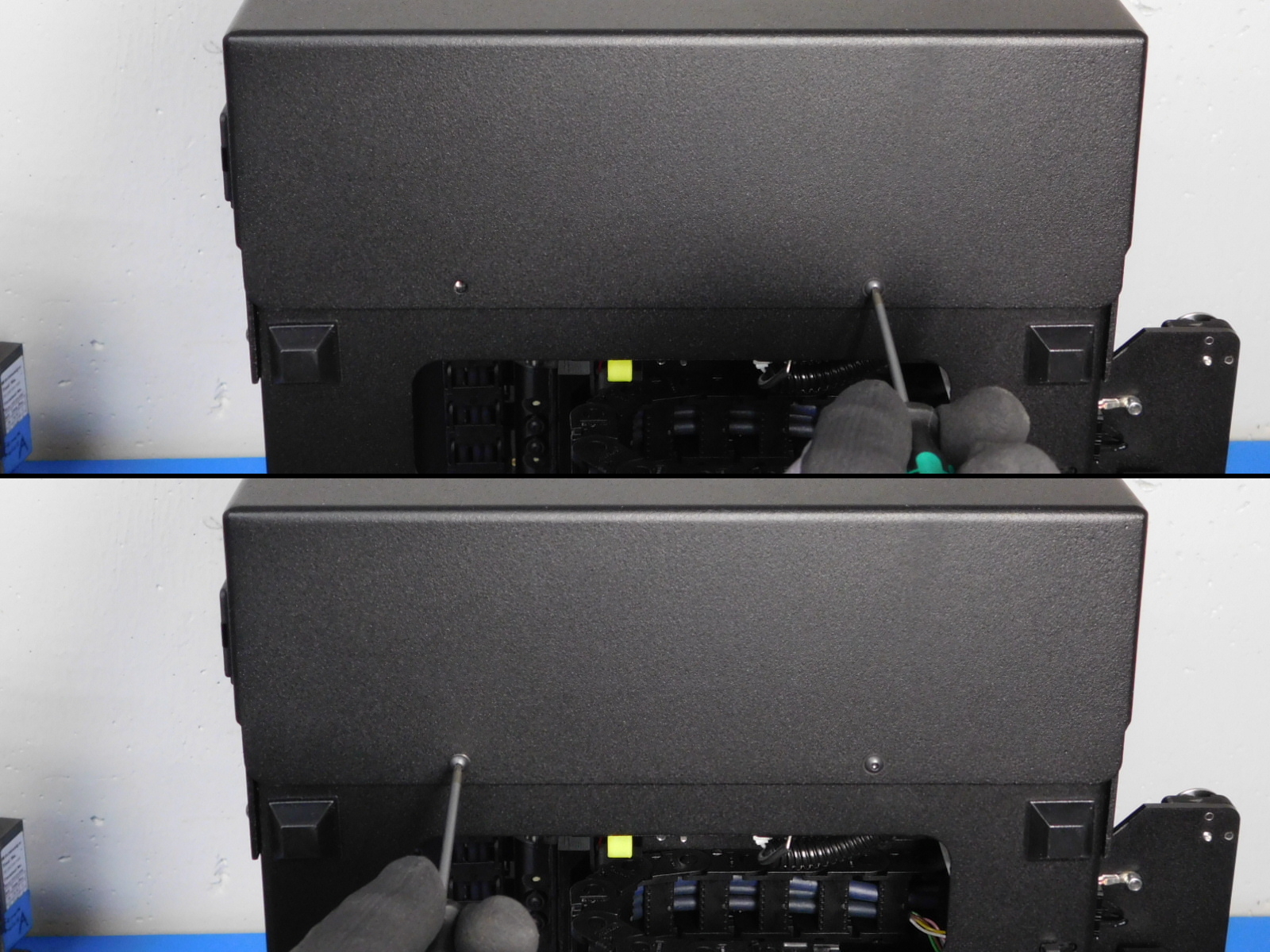
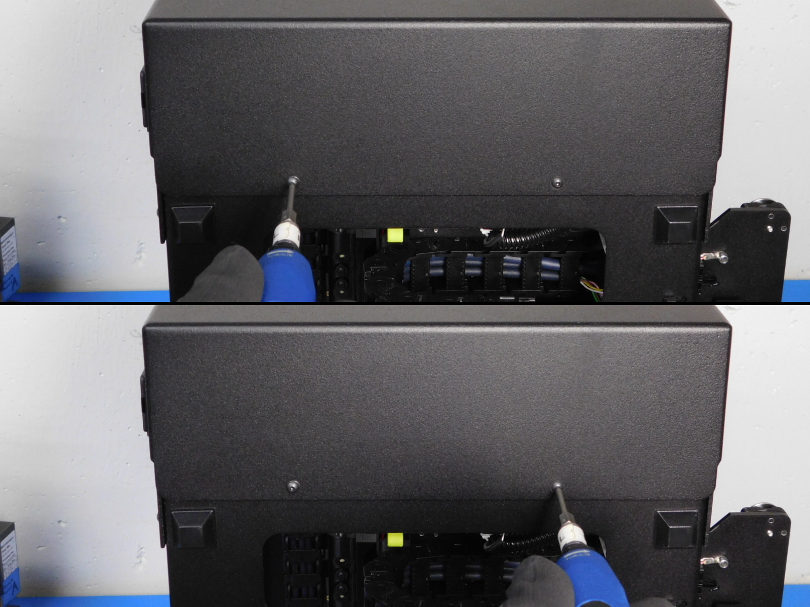
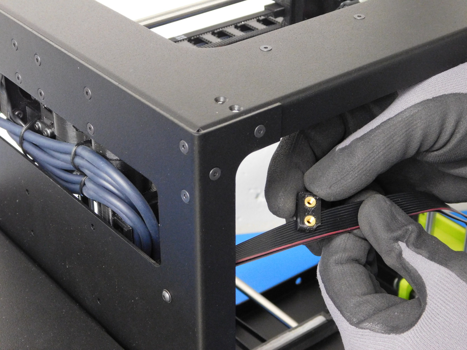
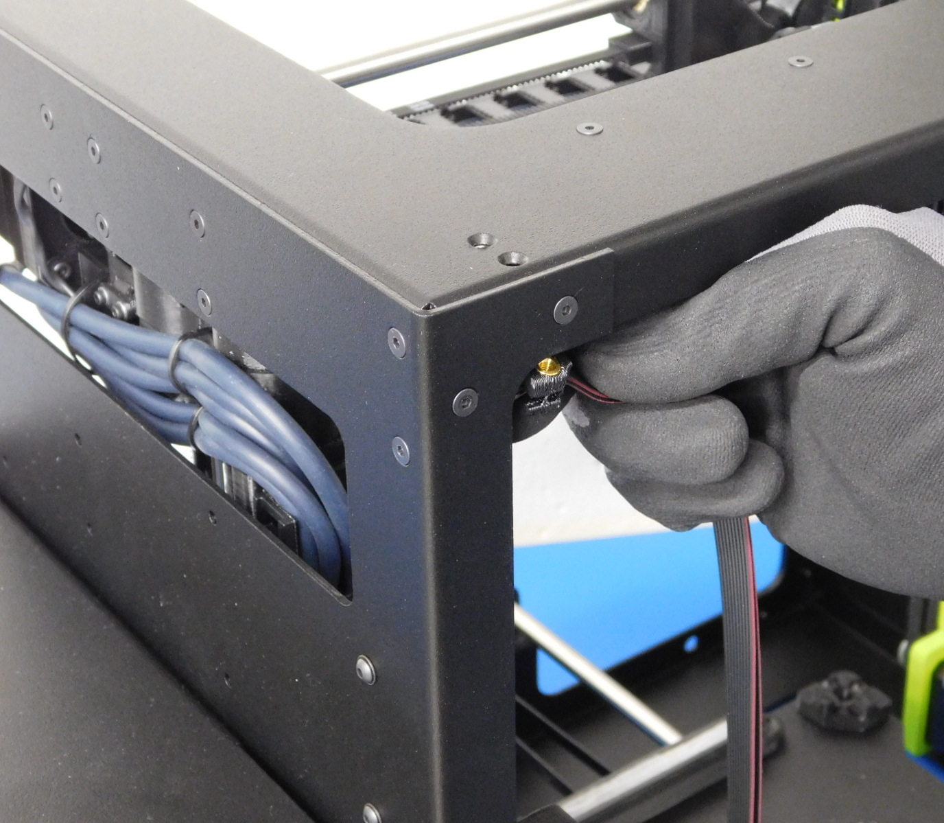
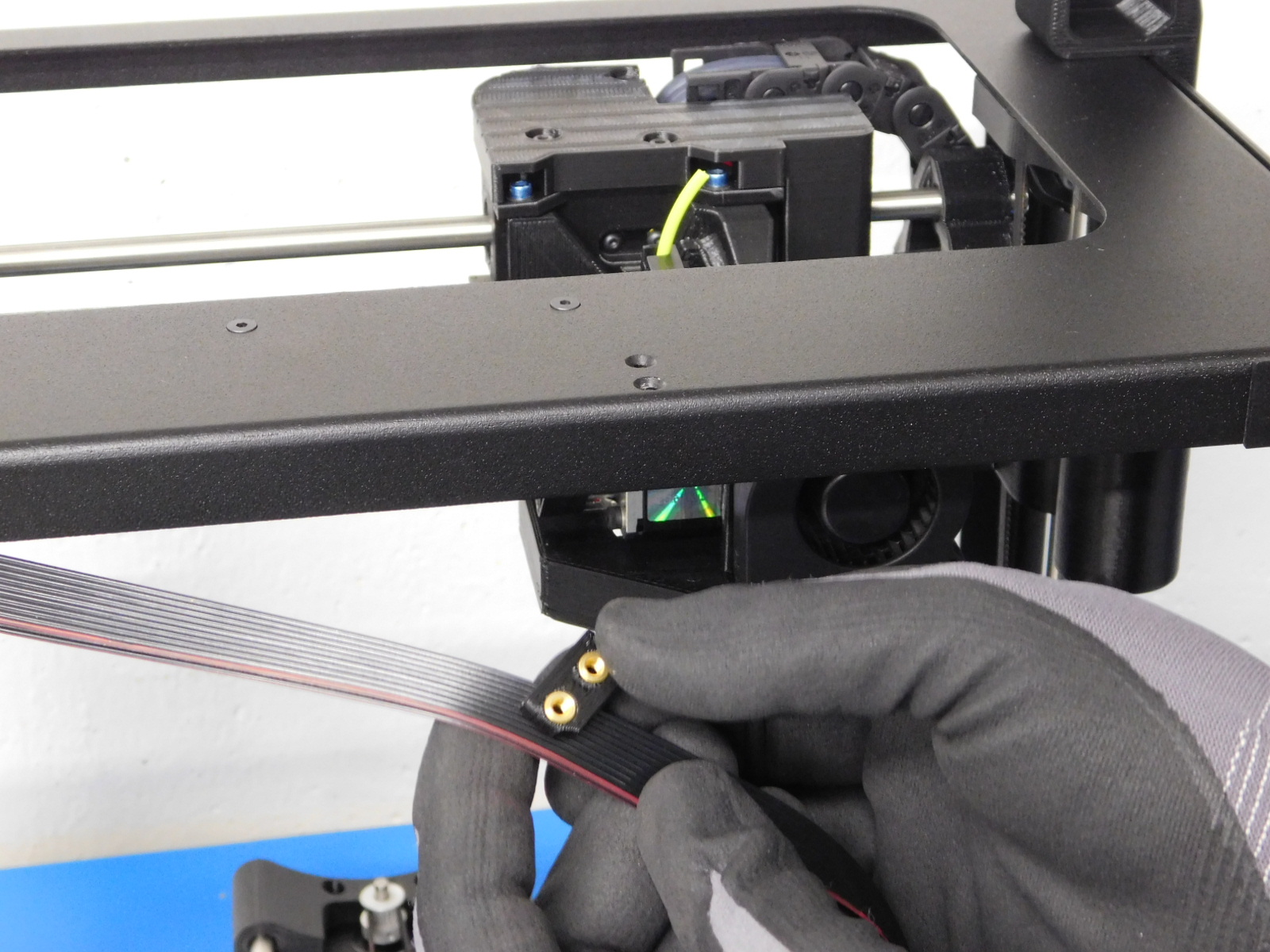
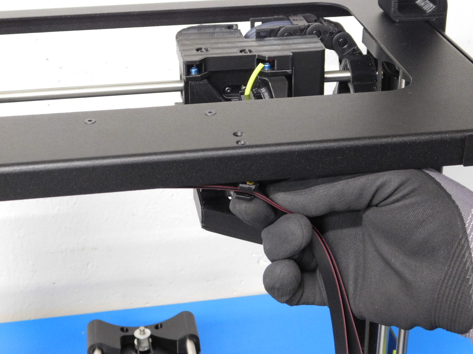
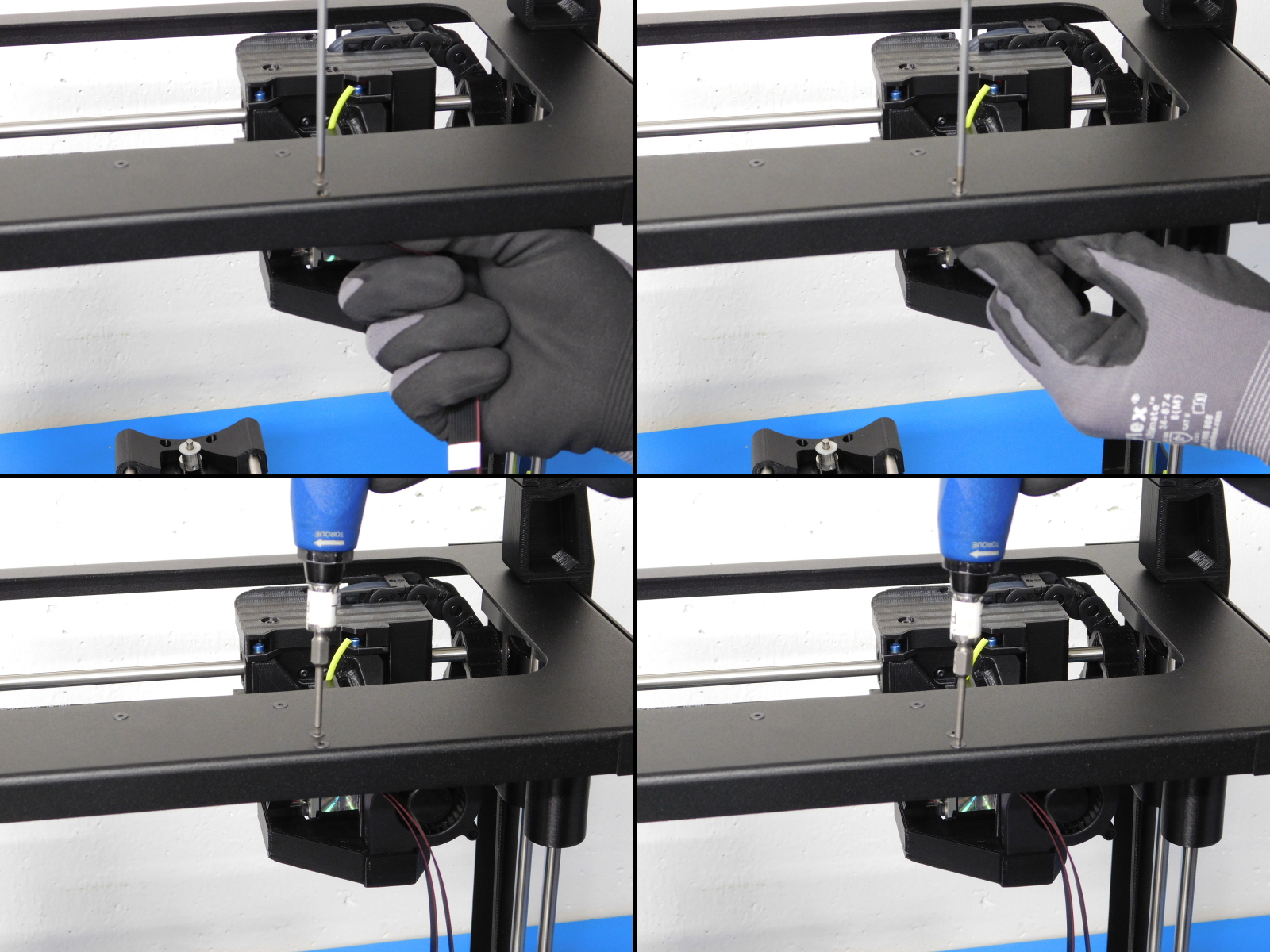
Thread harnesses through the side cable bracket, and hold in place above the frame hole. Adjust orientation so that holes align with frame.
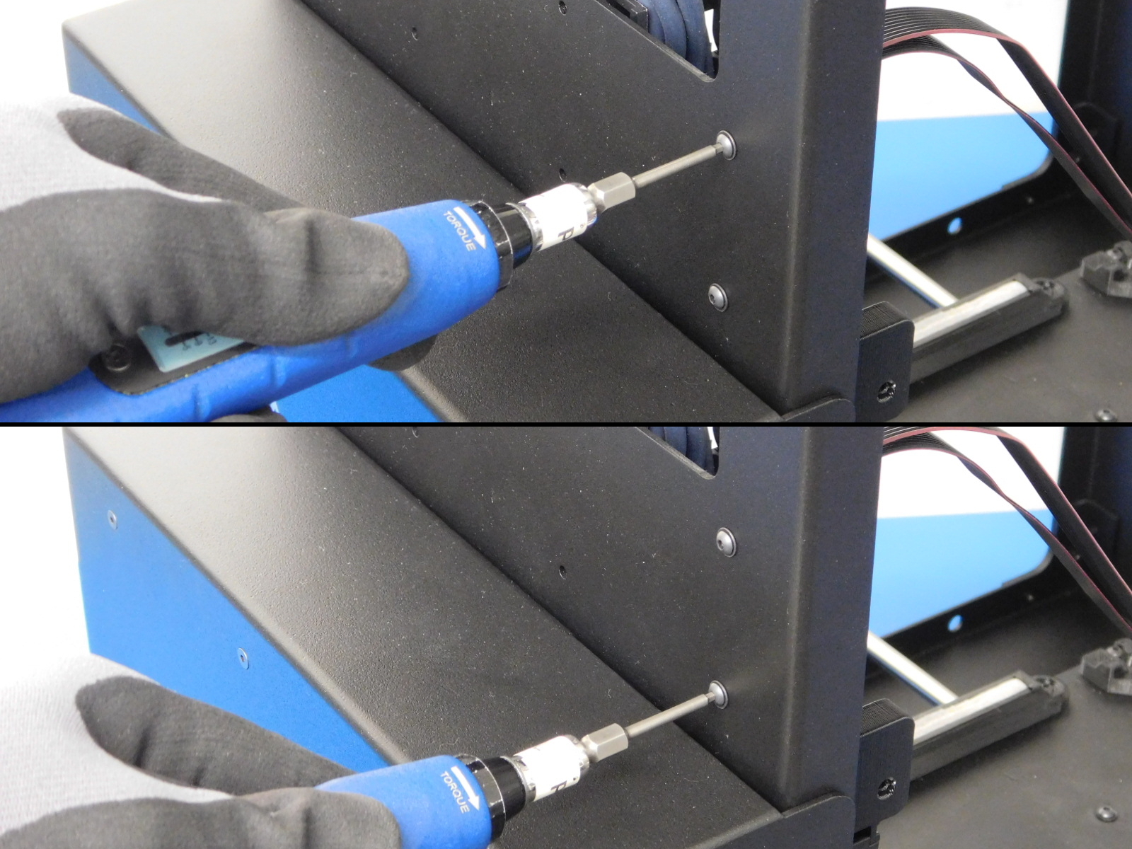
Secure the Side Cable Bracket [PP-IS0055] as pictured using two M3x8 BHCS [HD-BT0137] with washers [HD-WA0038]
Torque to 5in*lbs
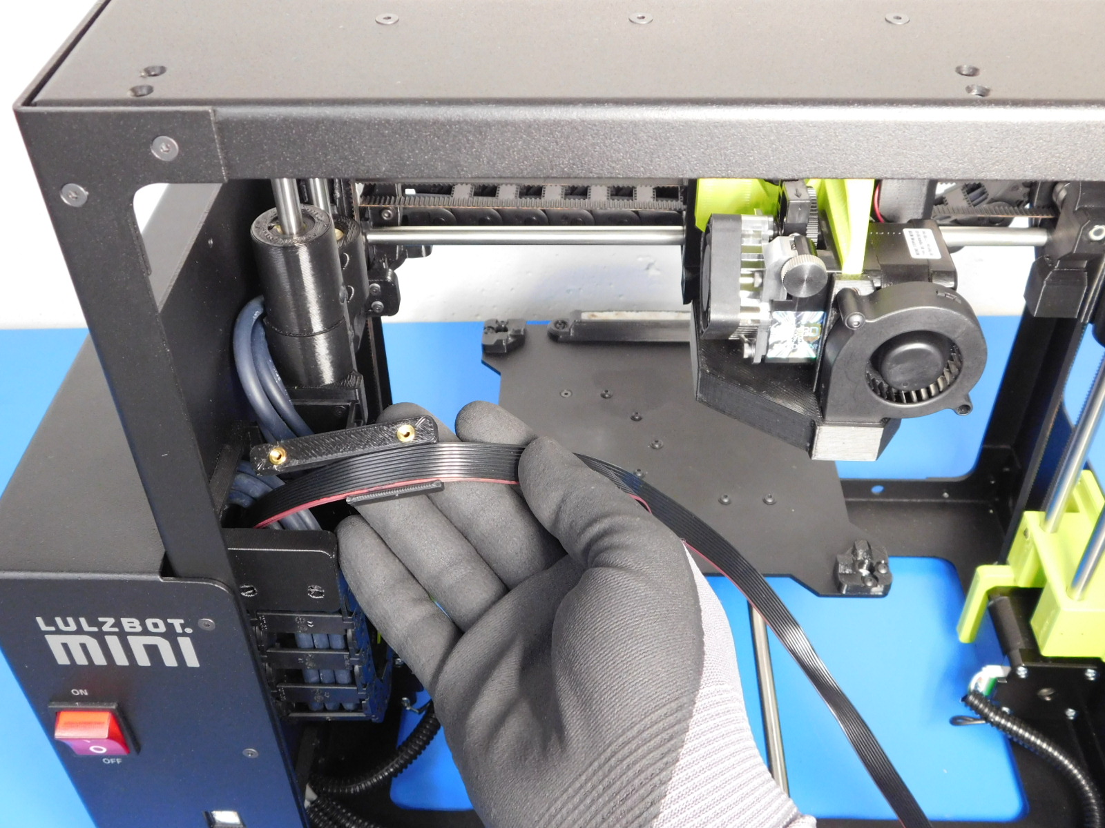
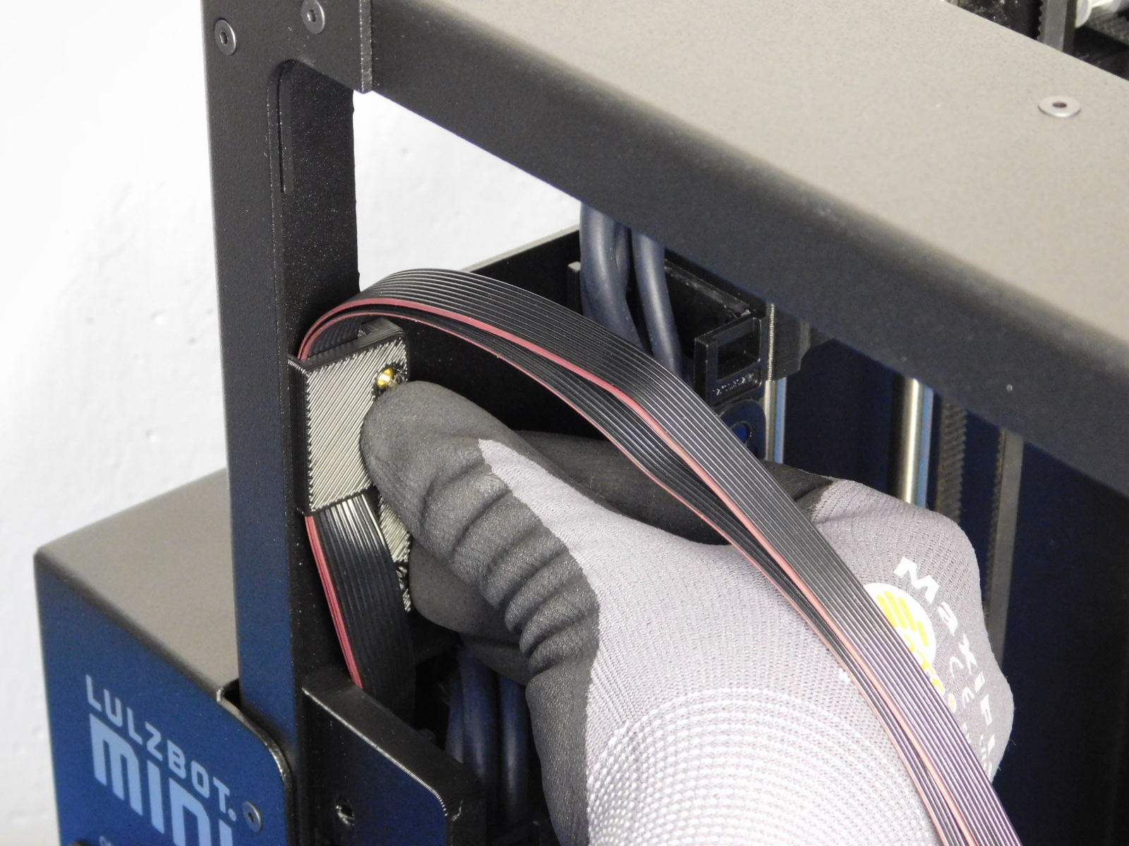
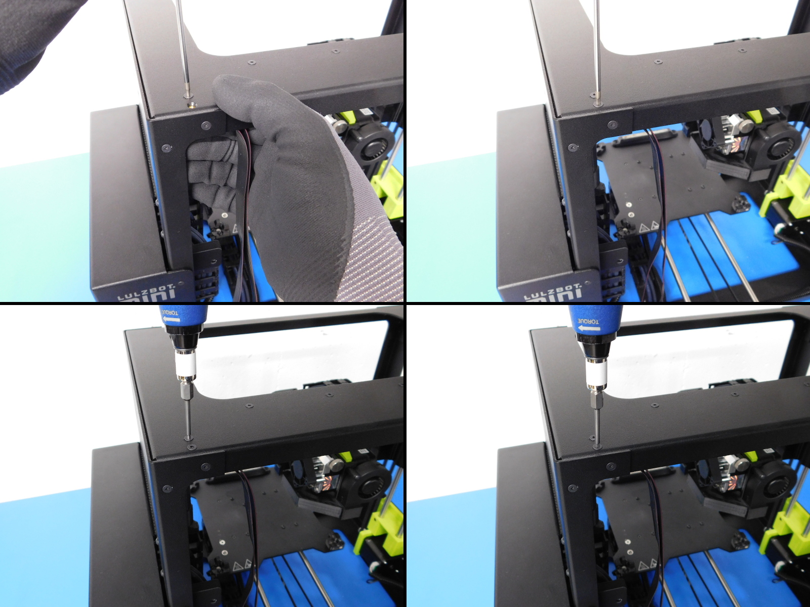
Slide a Top Cable Bracket [PP-IS0054] over both LCD Harnesses and line up with holes in top plate, starting with the two on the left.
Secure using two M3x6 FHCS [HD-BT0128]
Torque to 3in*lbs
Slide another Top Cable Bracket [PP-IS0054] over both LCD Harnesses and line up with holes in top plate towards the right.
Secure using two M3x6 FHCS [HD-BT0128]
Torque to 3in*lbs
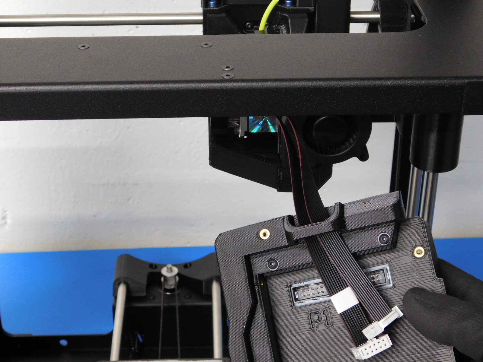
Thread the harnesses down through clip on the back of the LCD Assembly [AS-EL0002] as shown in image.
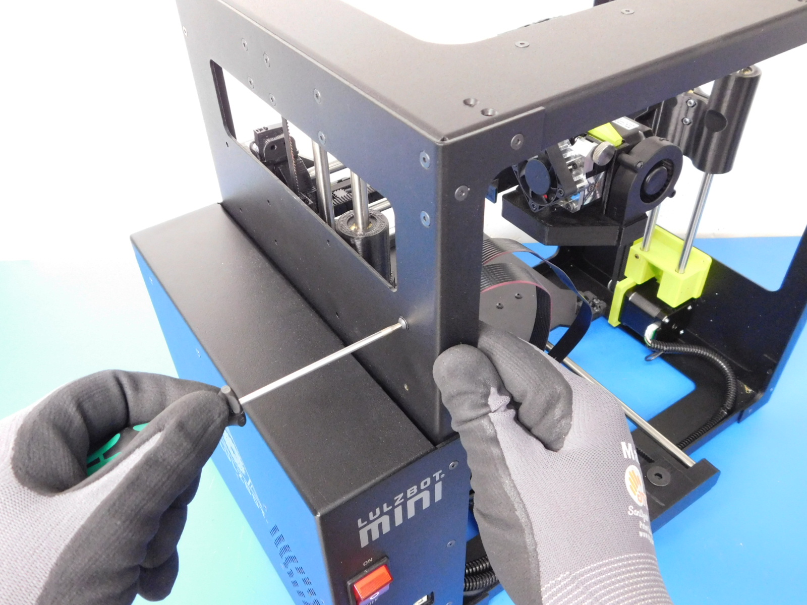
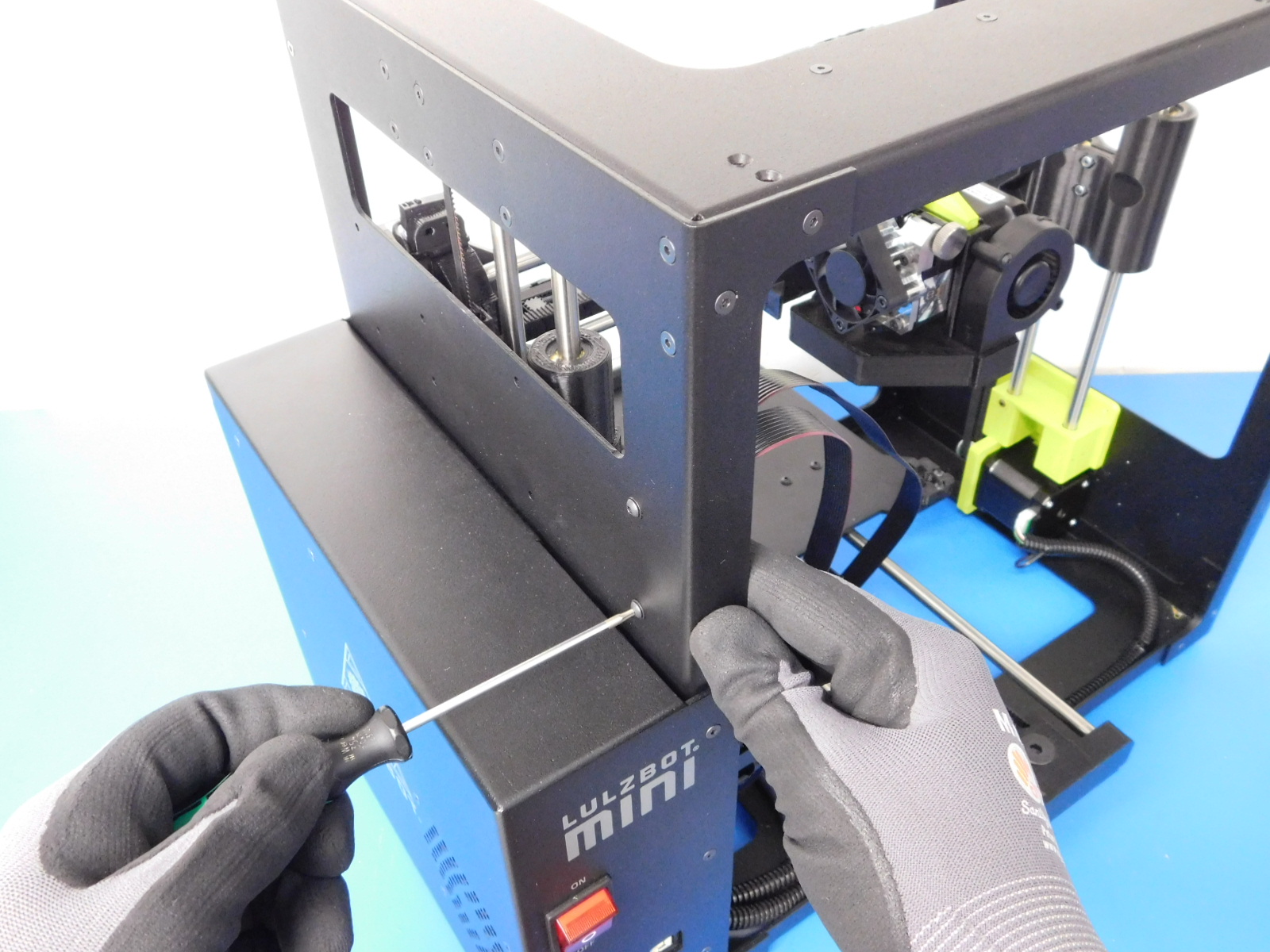
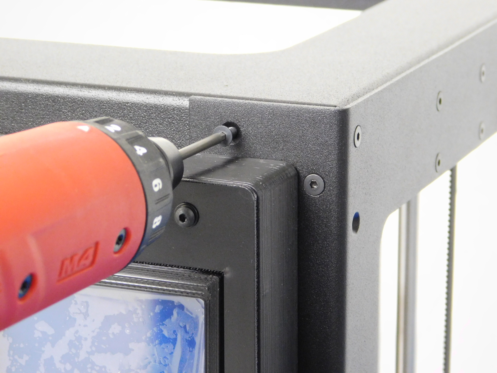
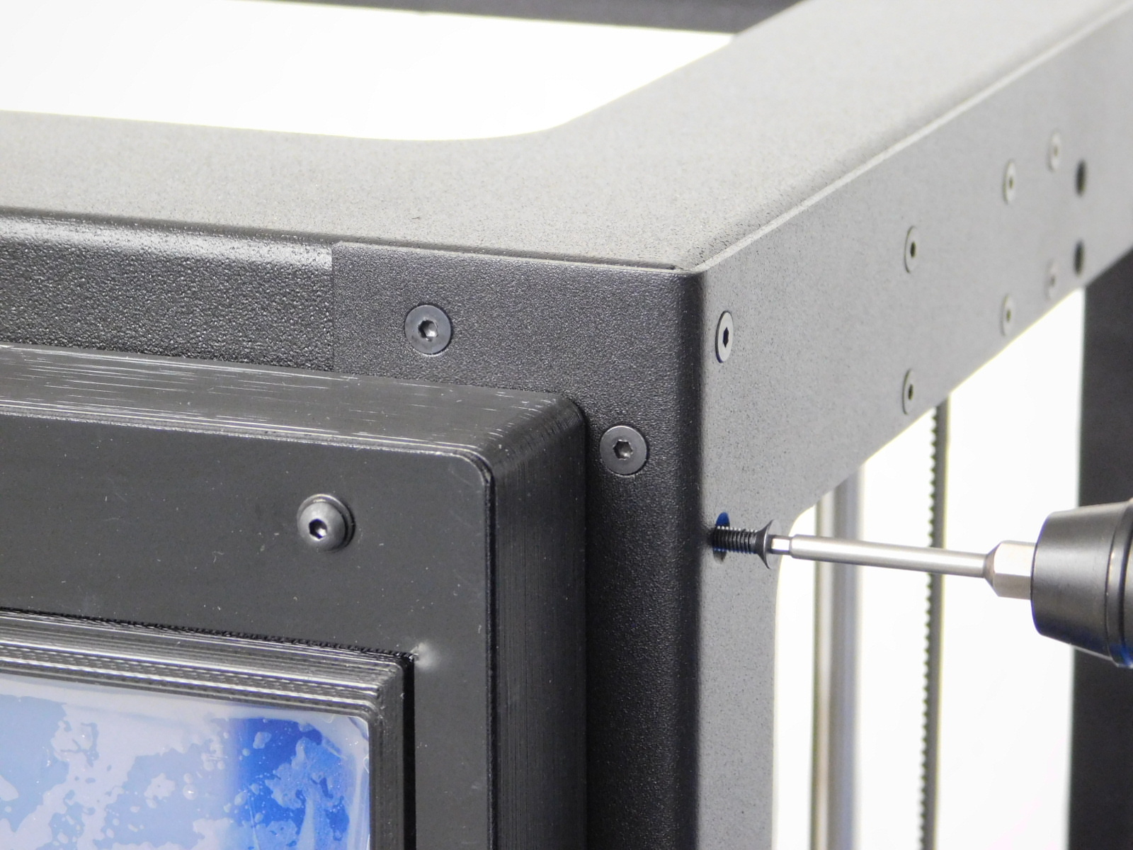
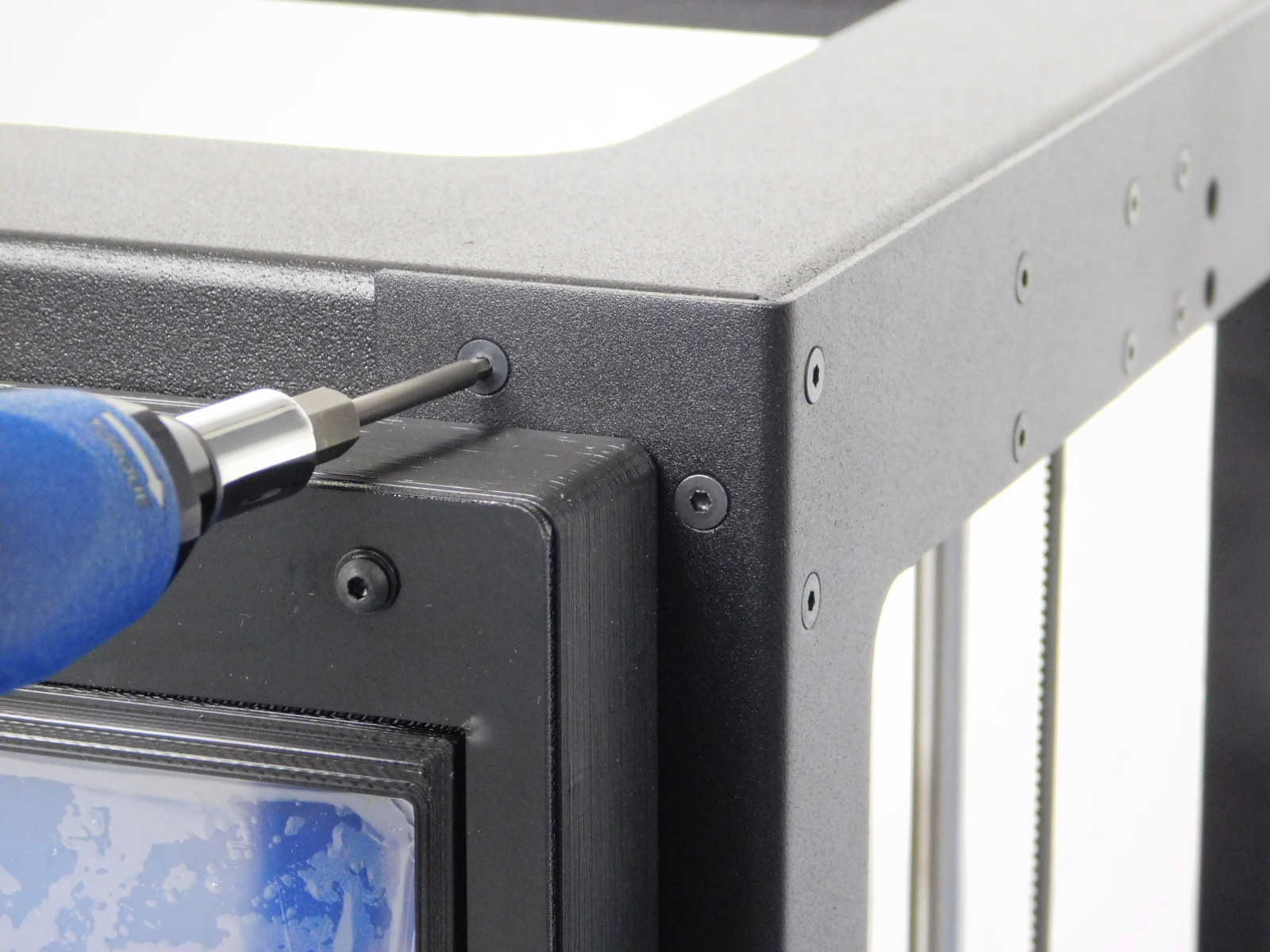
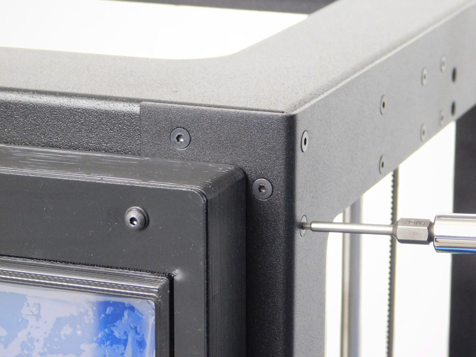
Using two M3x25 FHCS [HD-BT0206], secure the LCD Assembly [AS-EL0002] to the front top right corner of the machine.
The screws go in the open holes on that corner of the frame.
Torque to 5in*lbs
NOTE: Be cautious when securing the LCD Assembly that you are not pinching your LCD cables underneath the mount.
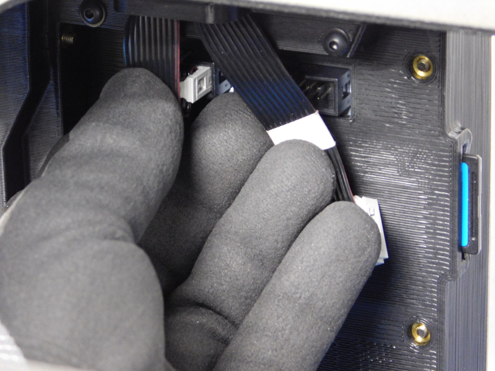
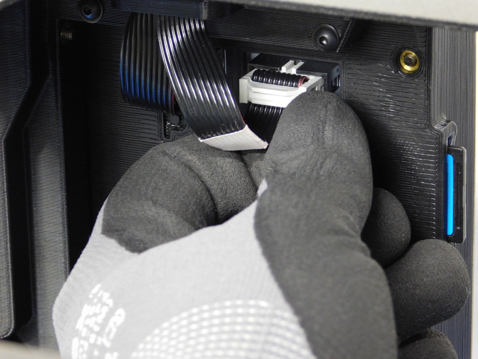
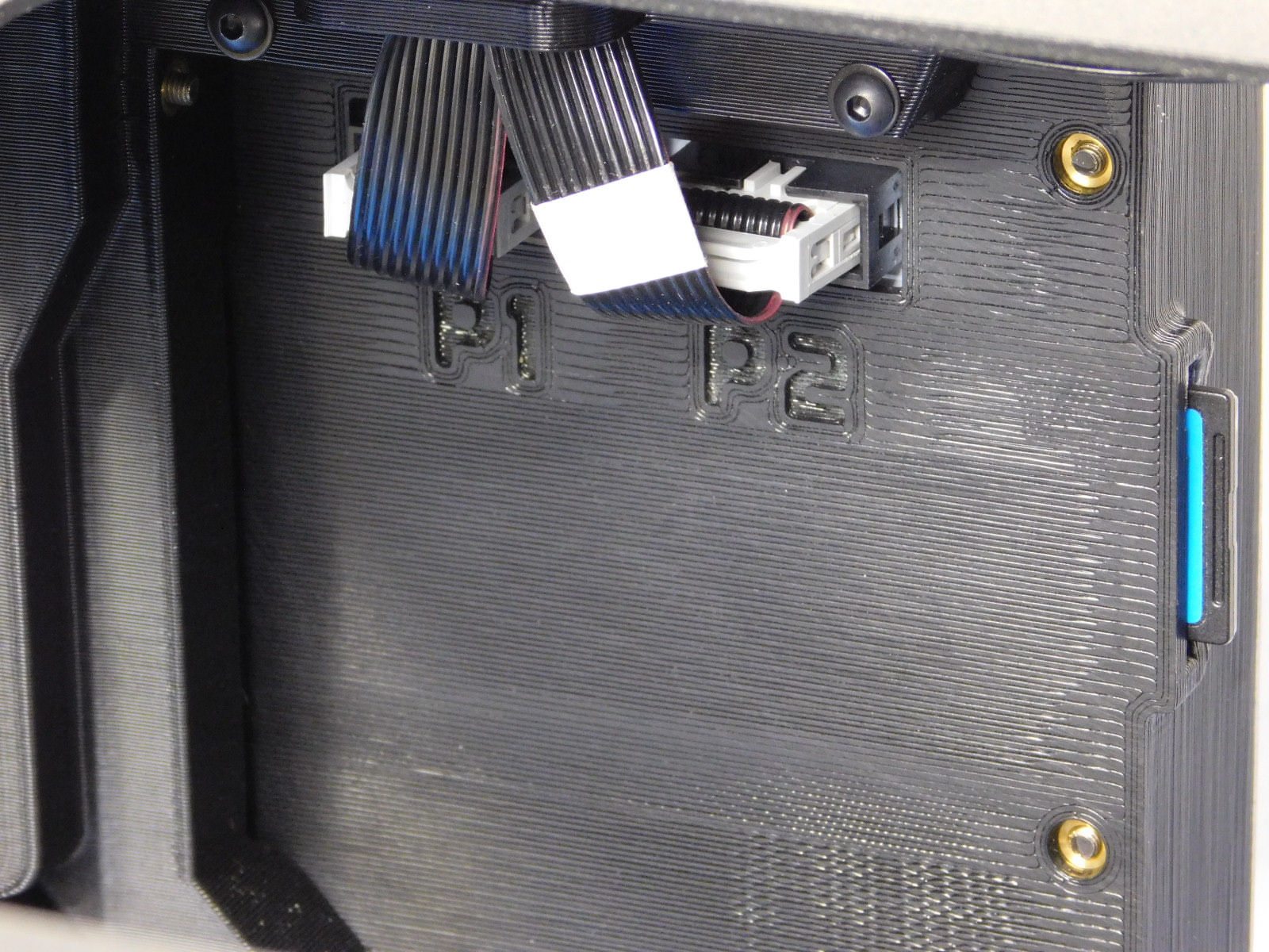
Connect LCD Harness 1 [AS-CB0083] (without white label) to P1 on the back of the LCD Controller as pictured.
Connect LCD Harness 2 [AS-CB0084] (with white label) to P2 on the back of the LCD Controller as pictured.
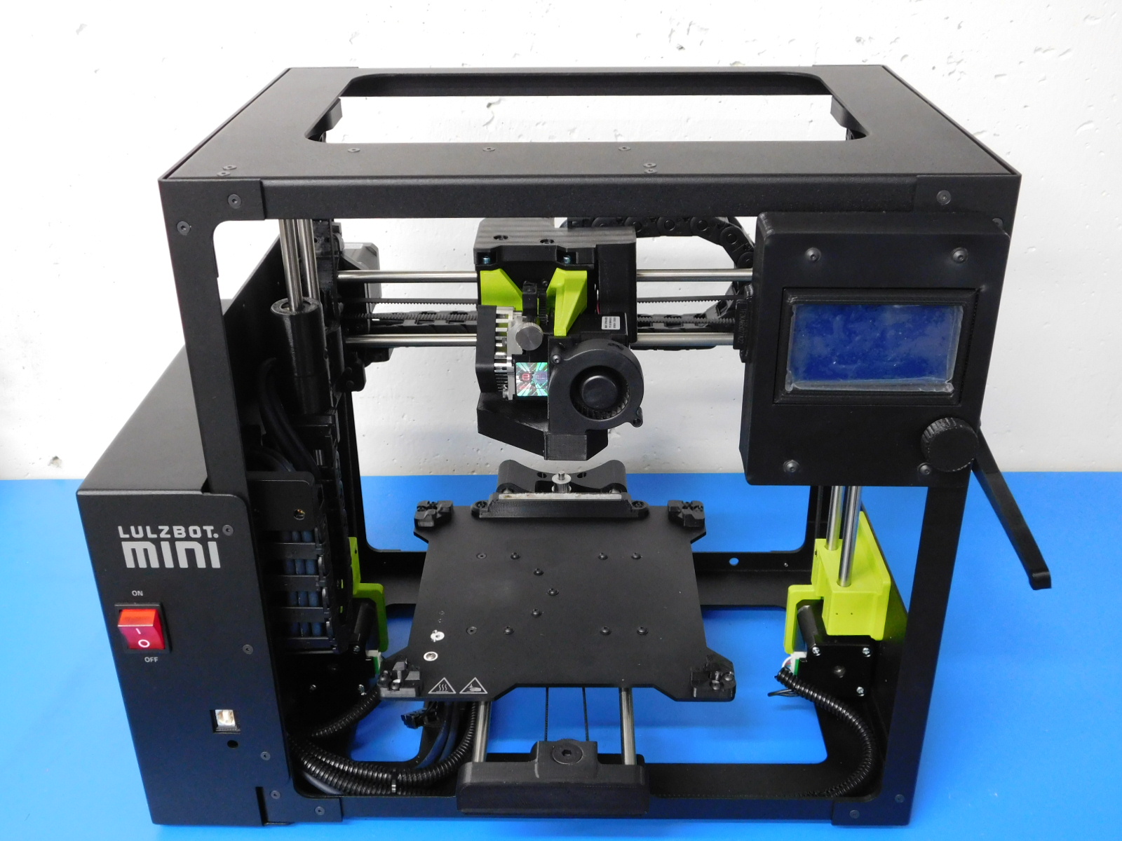
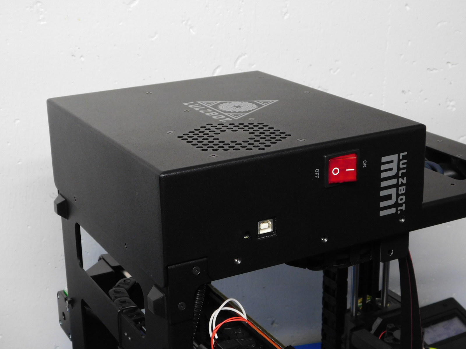
Verify all steps have been completed properly and your assembly resembles the picture shown at right.