Open HardwareAssembly Instructions
Guides for installation and assembly of the LulzBot line of products made by Aleph Objects, Inc.
Guides for installation and assembly of the LulzBot line of products made by Aleph Objects, Inc.
Required materials:
1x- [DC-LB0153] Ground Symbol Sticker
1x- [DC-LB0156] Electric Shock Warning Sticker
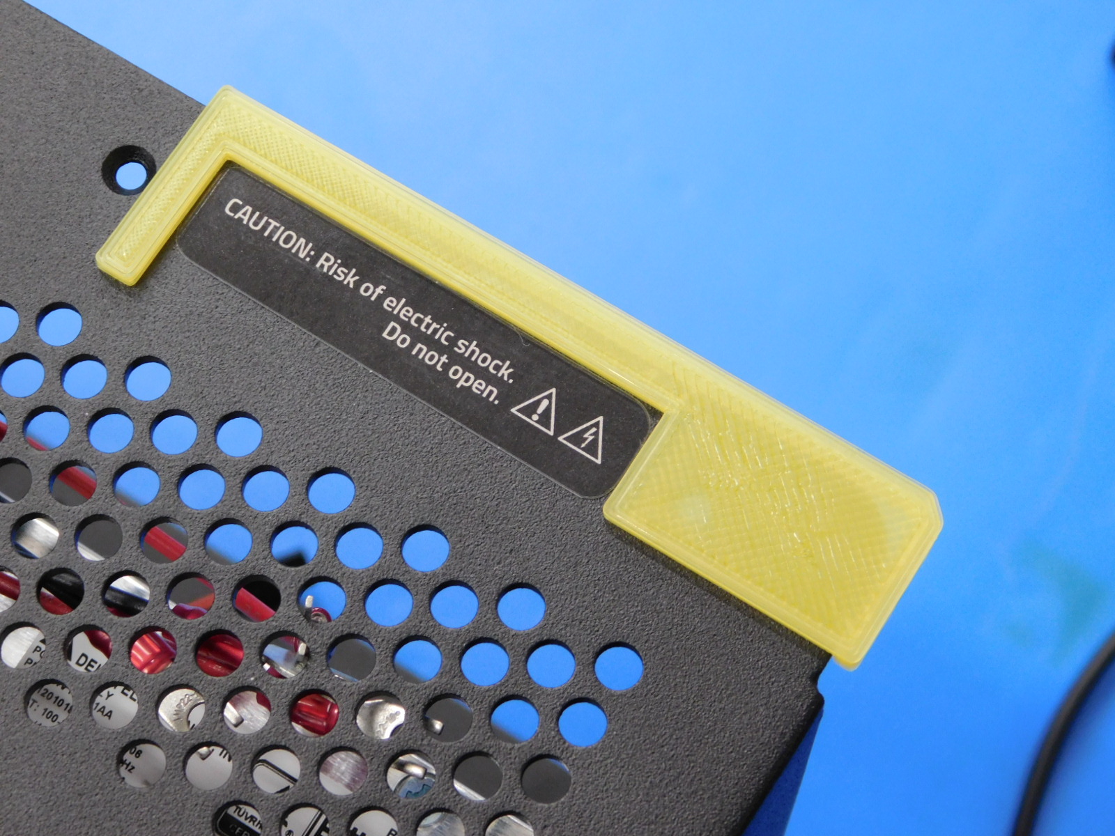
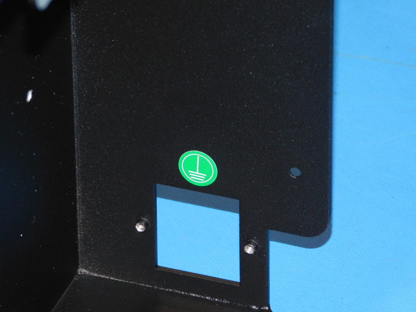
Apply the Electric Shock Warning sticker [DC-LB0156] to the Electronics Case in the position and orientation shown.
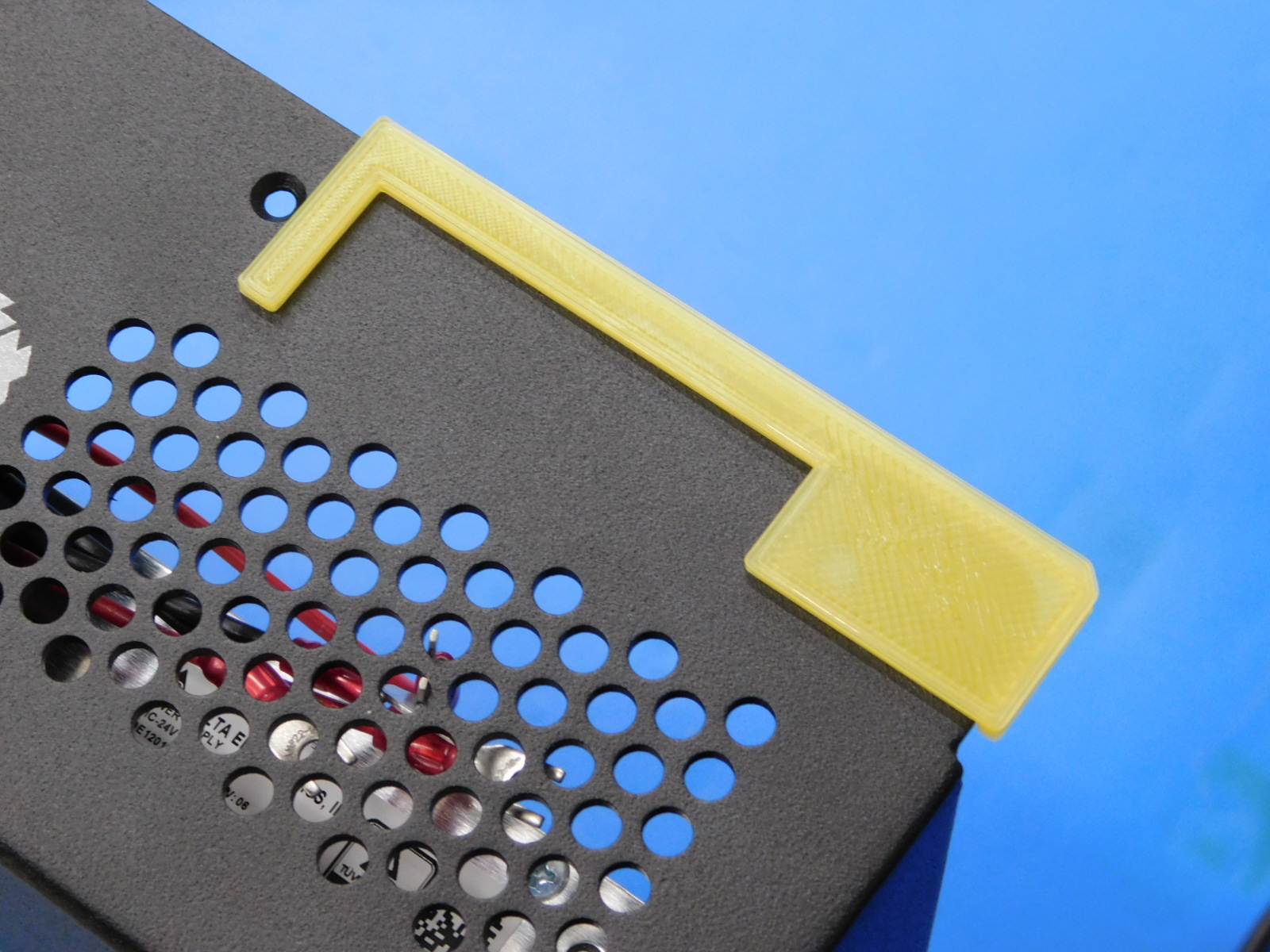
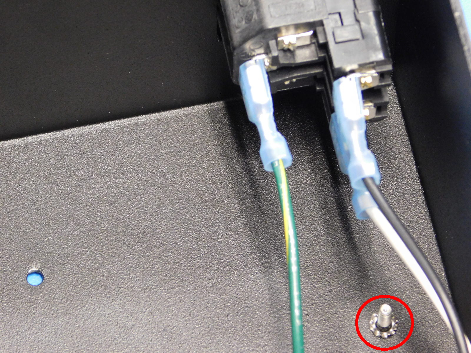
Apply one Ground Symbol Sticker [DC-LB0153] centered above the receptacle punch-out on the inside of the electronics case, as pictured.

Materials Needed:
1x- [EL-PS0025] 150W 24V Power Supply
1x- [AS-CB0076] Switch to PS Extension black
1x- [AS-CB0077] Switch to PS Extension white
2x- [AS-CB0074] PS to EinsyRetro Red Wire
2x- [AS-CB0081] PS to EinsyRetro Black Wire
Tools Needed:
Phillips Screwdriver
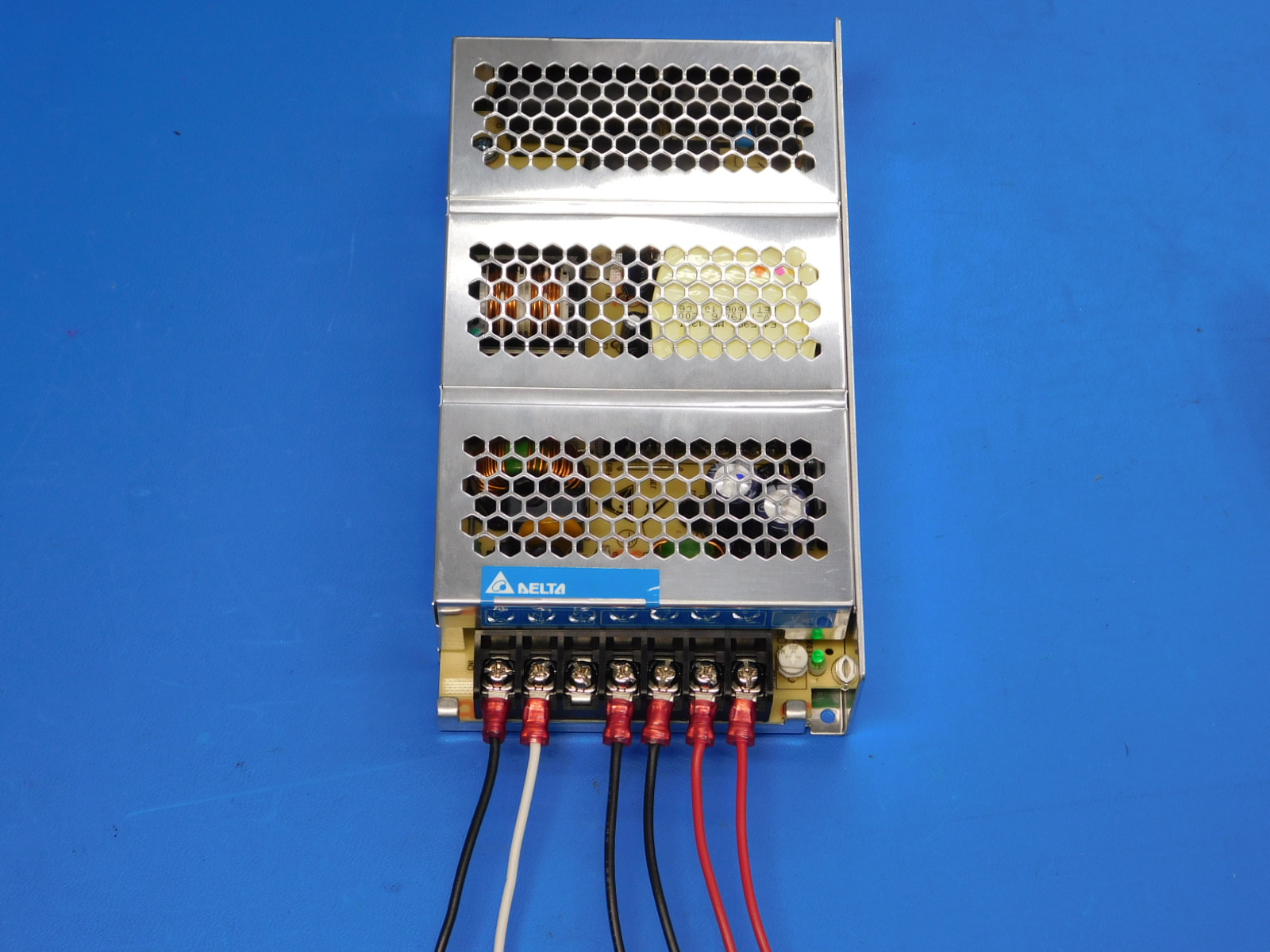
Attach the following cables to the 150W 24V Power Supply (EL-PS0025):
Switch to PS Extension black [AS-CB0076], Switch to PS Extension white [AS-CB0077], 2x PS to EinsyRetro Black [AS-CB0081], 2x PS to EinsyRetro Red [AS-CB0074]
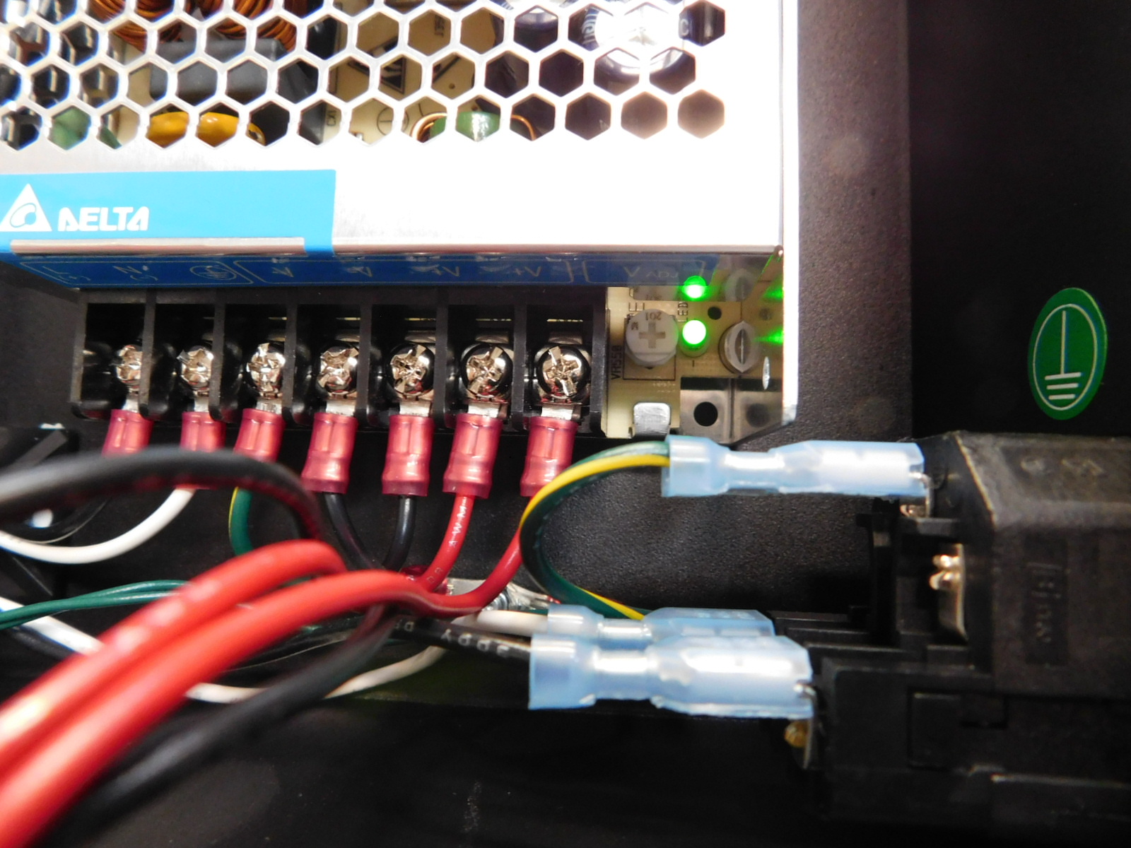
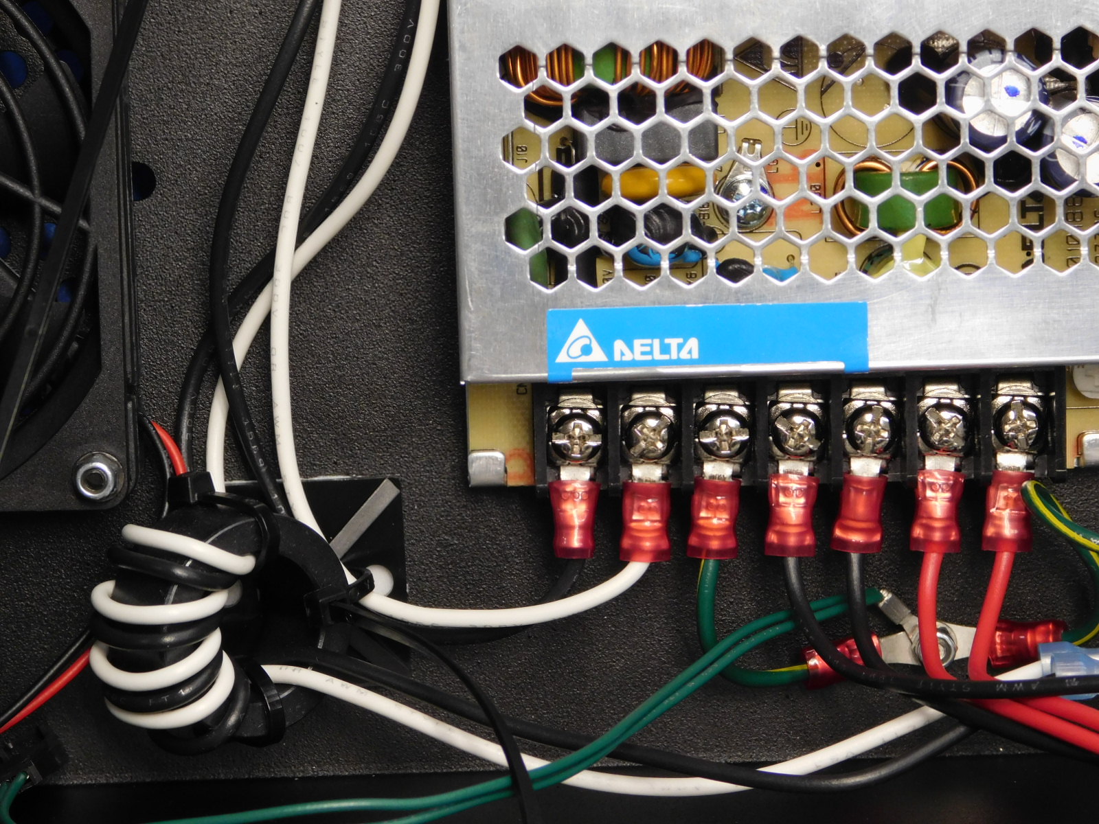
With the terminal block side of the power supply facing towards you, install Switch to PS Extension black [AS-CB0076] and Switch to PS Extension white [AS-CB0077] cable assemblies on the two far left terminals, attach the black cable to the far left terminal and the white cable to the second terminal in from the left (see picture).
Install 2x PS to EinsyRetro Black [AS-CB0081] and 2x PS to EinsyRetro Red [AS-CB0074]. The two red cables attach to the two far right terminals on the terminal block. And the two black cables attach to the third and fourth terminals in from the right side of the terminal block (see picture).
Parts Needed:
1x- 150.876mm EMI shielding gasket (EL-MS0432)
1x- Electronics cover (PP-FP0139)
Tools Needed: None
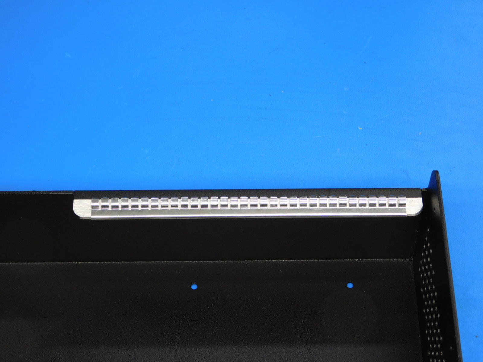
Carefully clip on the 150.876mm EMI shielding gasket (EL-MS0432) to the flange on the case.
Parts Needed:
2x- Cable tie downs (HD-MS0249)
Tools Needed:
Control Box Tie Down Jig
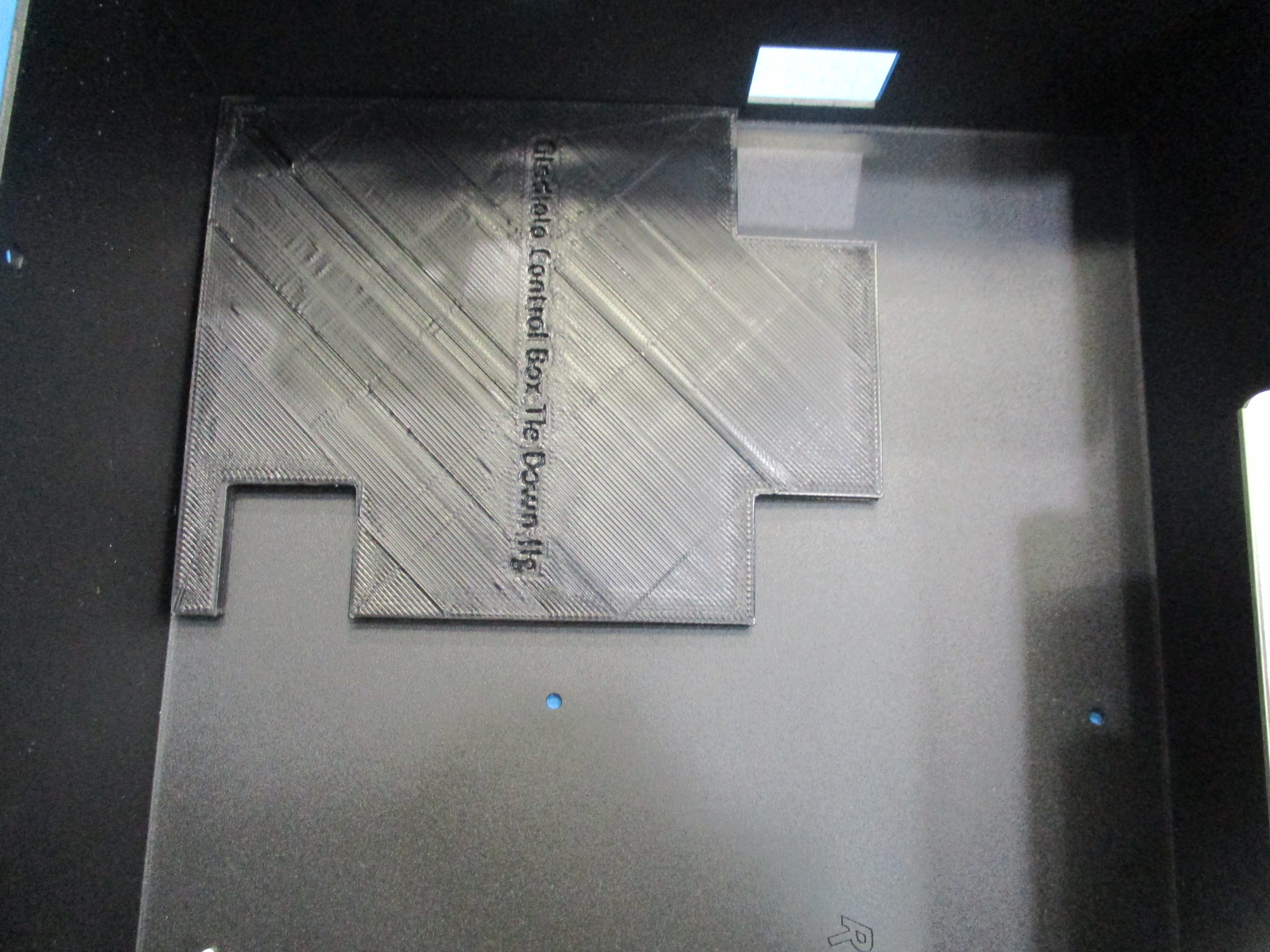
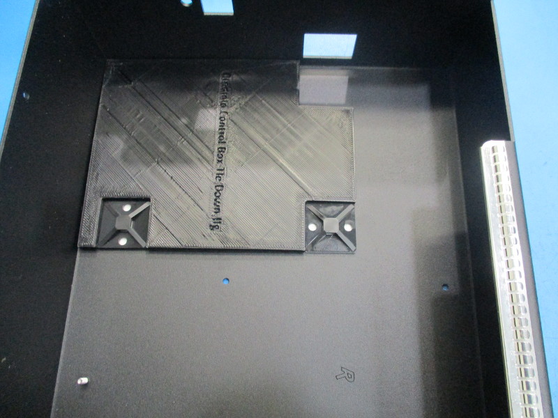
Install two cable tie downs (HD-MS0249) to the inside of the electronics case.
The first tie down is installed 95mm from the switch side of the case and 10mm up from the bottom of the case (see picture).
The second tie down is installed 95mm from the switch side of the case and 65mm down from the top of the case (see picture).
Materials Needed:
2x- [HD-BT0130] M3x8mm Black Oxide Flat Head Cap Screws
1x- [PP-MP0028] AC power entry module
2x- [EL-MS0414] 250V 3.15A Slo-Blo Cartridge fuses
1x- [EL-SW0023] Rocker Switch
1x- [AS-CB0073] Plug to Switch Extension
1x- [AS-CB0079] Plug to Ground Post Extension
1x- [AS-CB0075] Earth Ground Extension
1x- [HD-WA0035] M3 external tooth lock washer
1x- [HD-NT0001] M3 Nylon lock nut
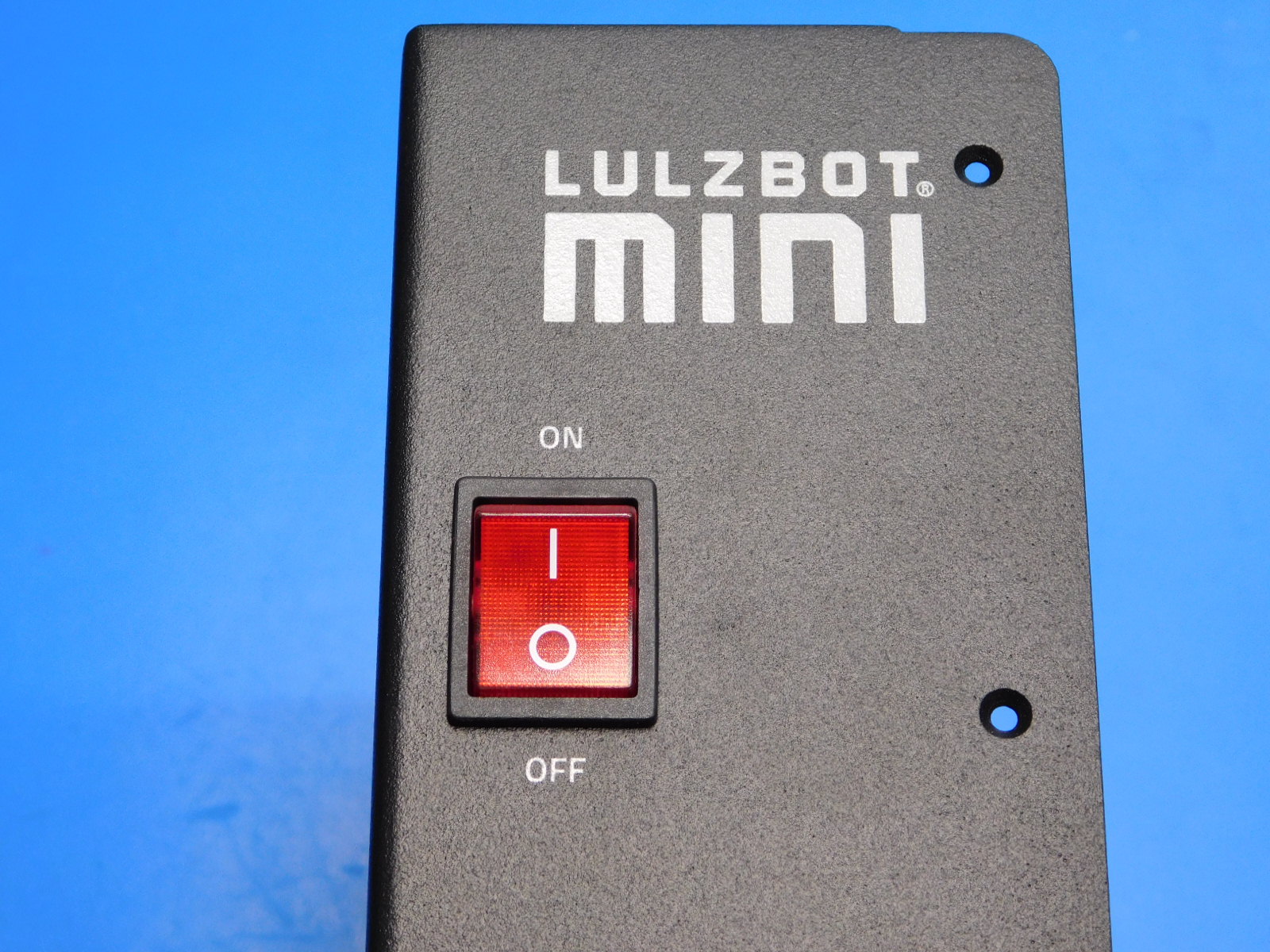
Install the rocker switch. See image for orientation
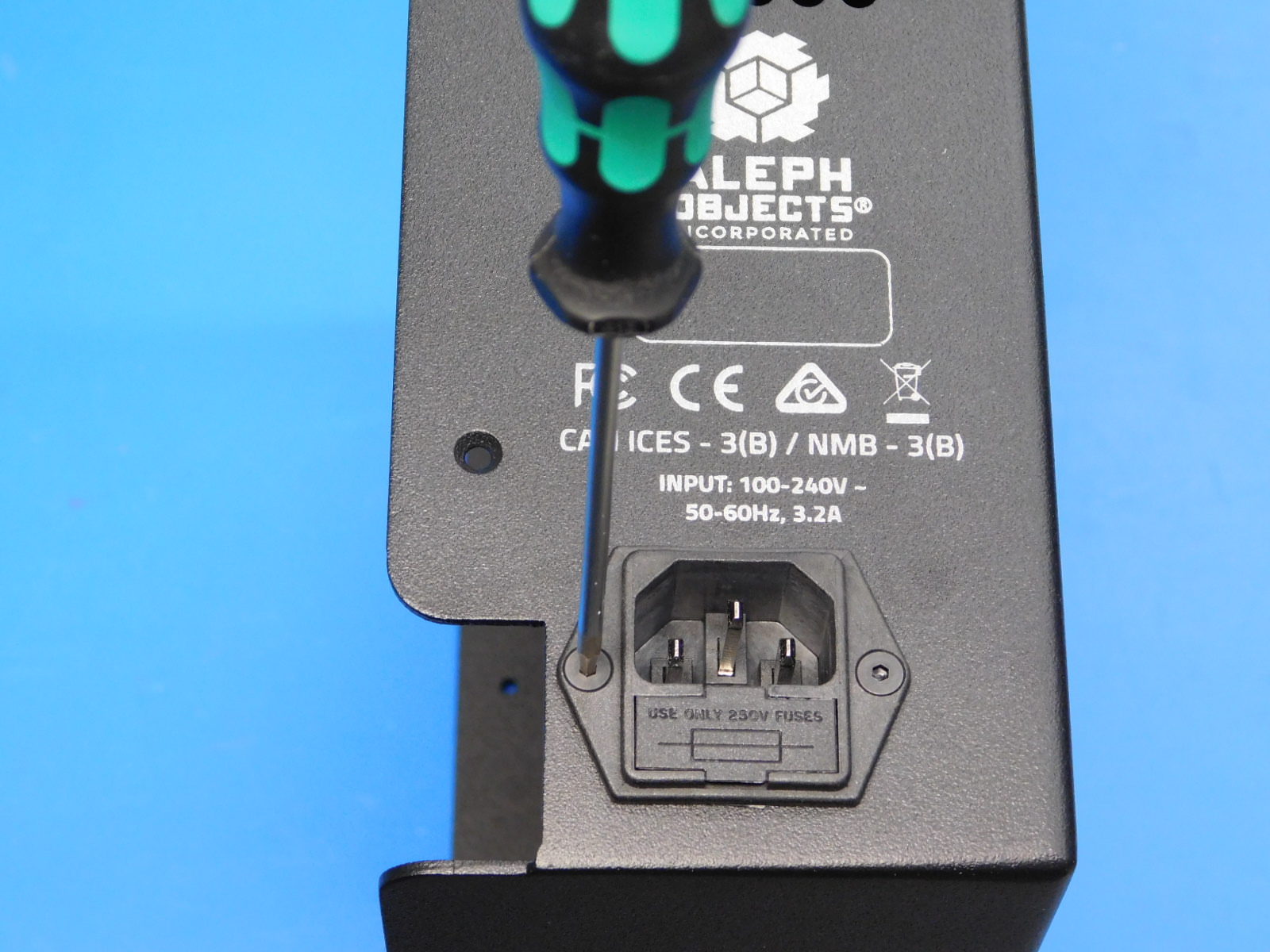
Install the power entry module using two M3x8 FHCS and torque to 3in*lbs.
Install two fuses into the power entry module by opening the fuse tray and inserting 2 fuses [EL-MS0414]
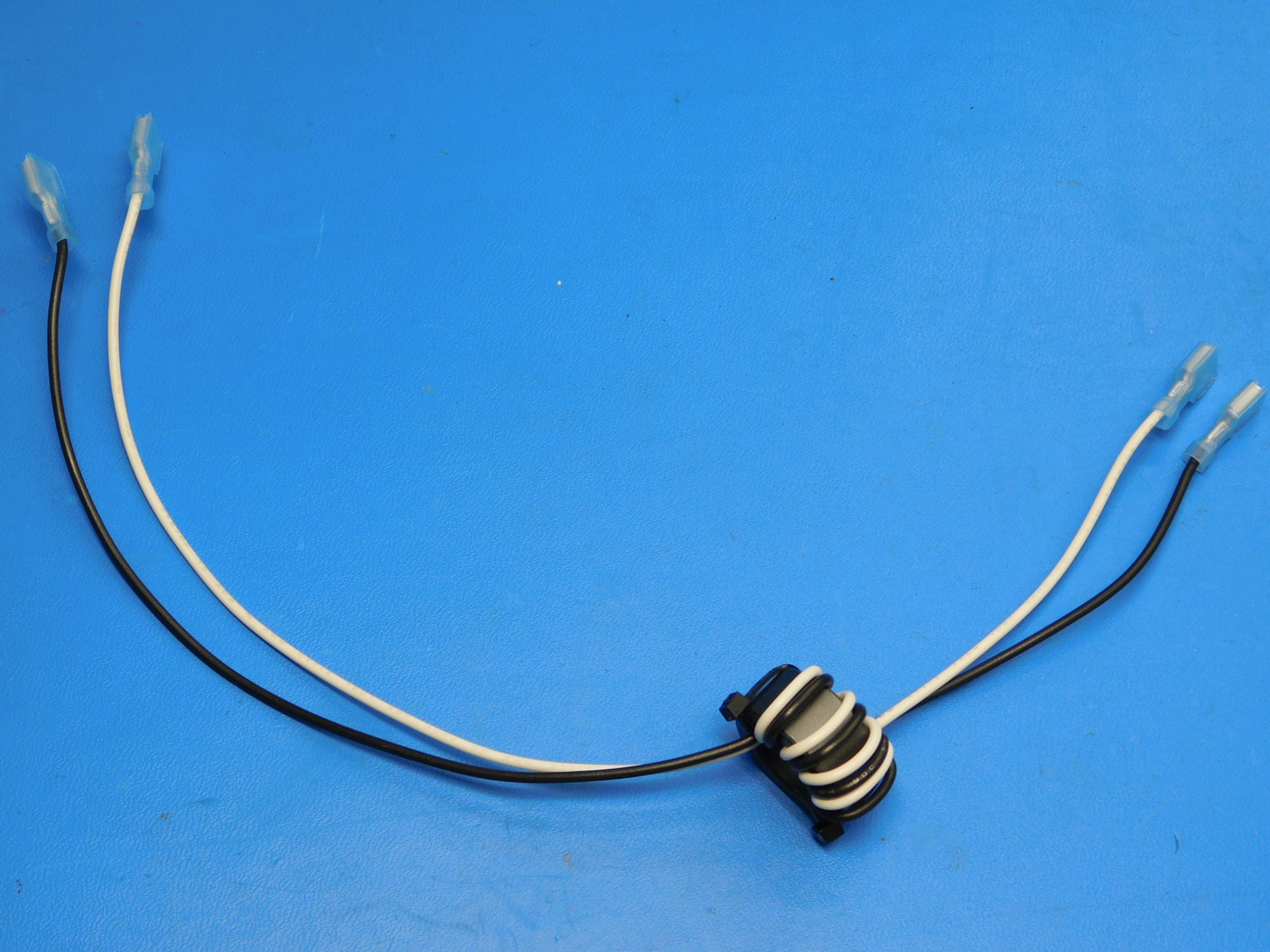
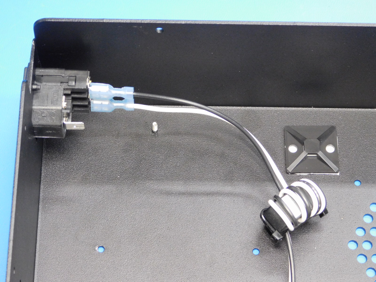
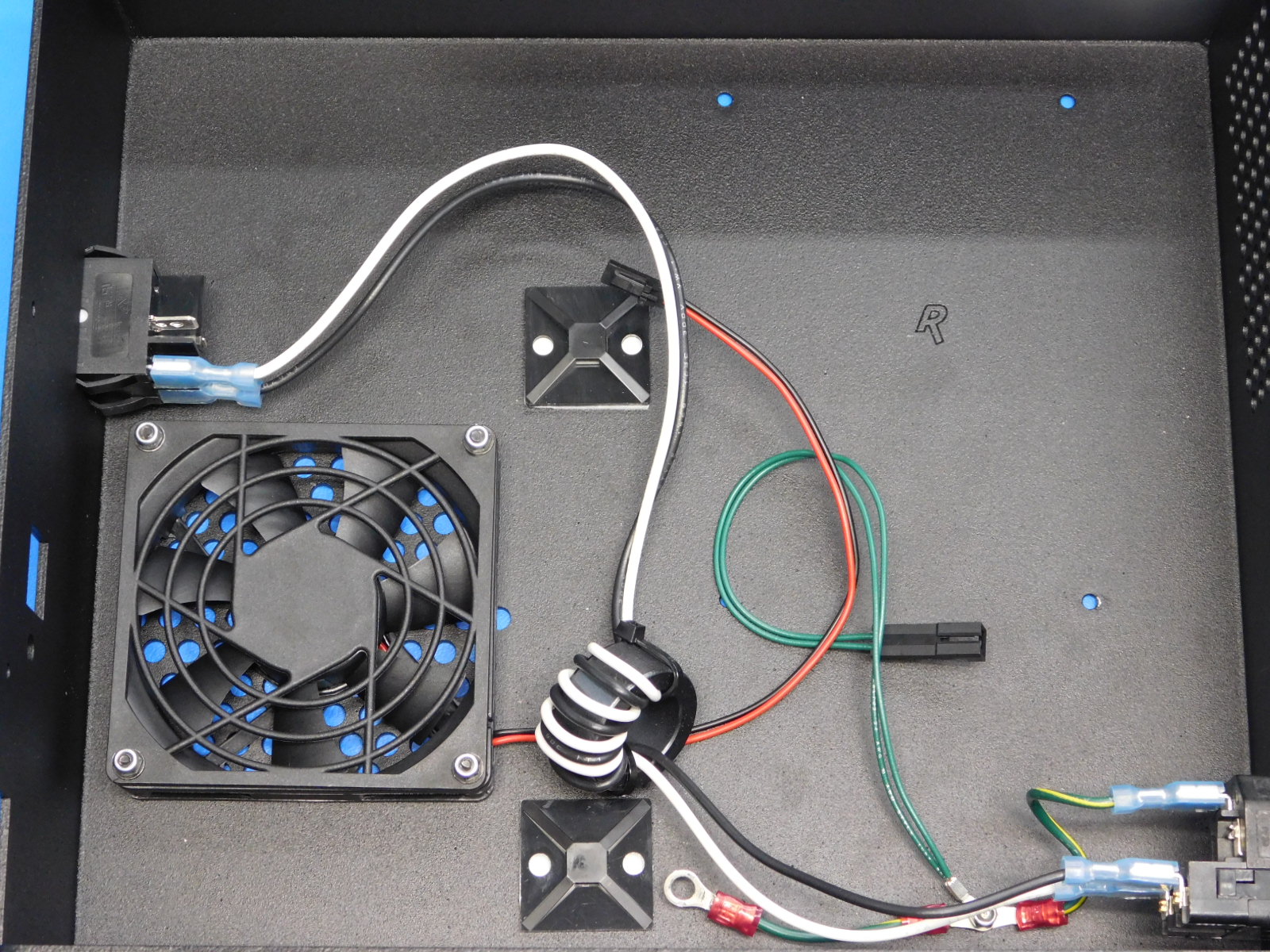
Attach the Plug to Switch Extension [AS-CB0073] cable to the power entry module and check our alignment of the cable with the cable tie downs. Attach the cable to the two main power entry module terminals. Attach with the white wire towards the inside of the case and the black wire towards the open side of the case(see picture). This cable is wrapped through a ferrite 3 times and the ferrite should line up with the tie down closest to the power entry module (see picture).
Attach the plug to switch extension cable to the switch side of the case. Attach the cable to the two terminals of the switch that are oriented toward the bottom of the case. The black wire attaches toward the inside of the case and the white wire attaches toward the open side of the case (see picture). Note the alignment of the ferrite with the cable tie down.
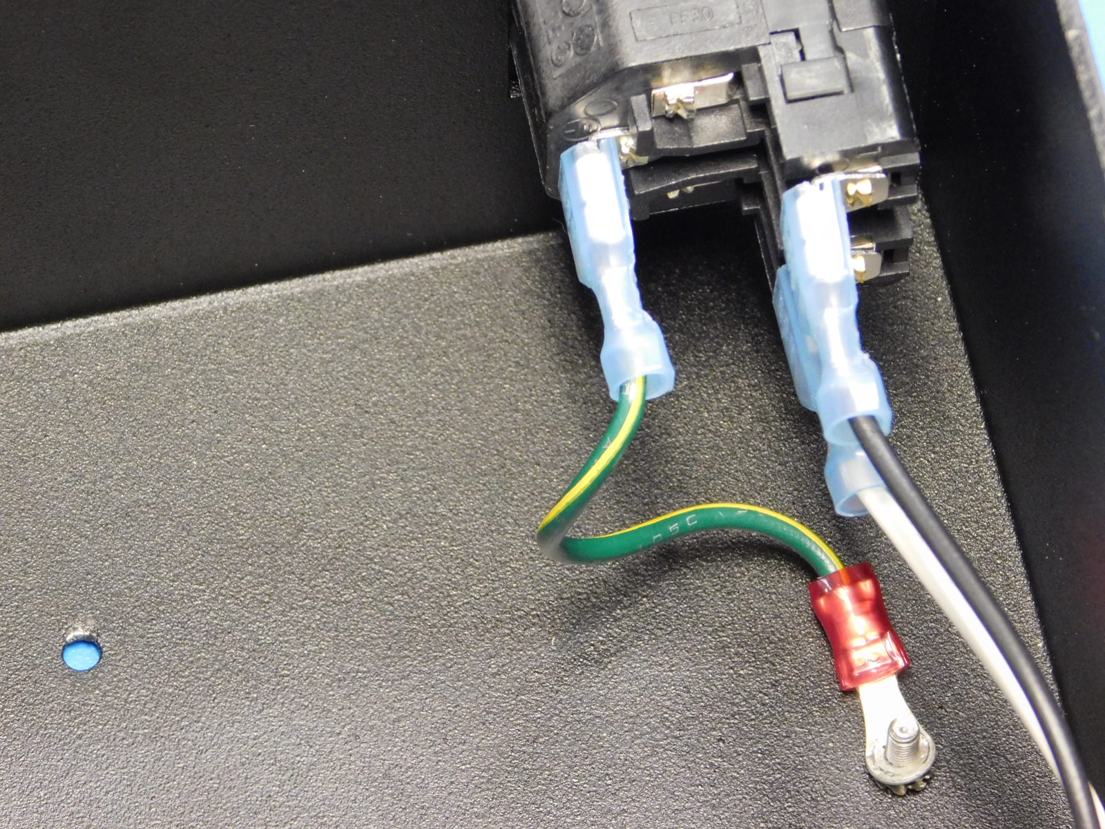
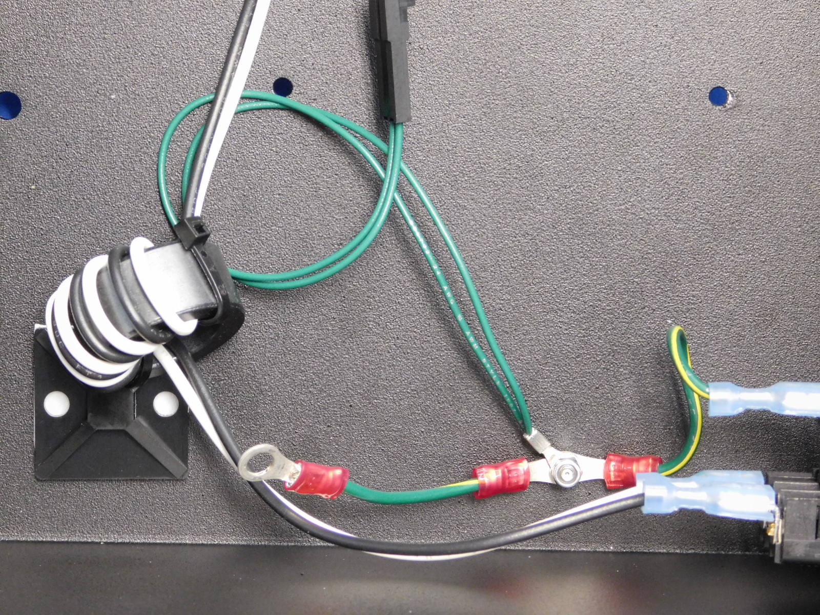
Attach the Plug to Ground Post Extension [AS-CB0079] cable. We attach the quick connect terminal end of the cable to the ground terminal on the power entry module, and the ring terminal end of the cable to the ground post inside the case (see picture). Before putting the ring terminal on the ground post install a M3 lock washer [HD-WA0035](see picture).
Attach the earth ground to the ground post.
Attach the small terminal ring end of the PS to Ground Post Extension [AS-CB0080] to the ground post.
Attach both terminal rings of the Earth Ground Extension [AS-CB0075] to the ground post and fasten with an M3 nyloc nut [HD-NT0001].
Parts Needed:
1x- [AS-CB0078] 80mm Case Fan Harness
1x- [EL-HR0109] 80mm finger guard
4x- [HD-BT0206] M3x25mm Black Oxide Flat Head Cap Screws
4x- [HD-WA0038] Black Oxide M3 Washers
4x- [HD-NT0001] M3 nylock nuts
Tools Needed:
2mm Hex Driver
5.5mm Nut Driver
Orient the 80mm Case fan harness [AS-CB0078] such that the sticker faces down and the wires are directed toward the bottom of the case and the plug. Place the 80mm finger guard [EL-HR0109] on top of the fan (note the installation warning on the fan guard and that the warning is followed).
Using 4x- M3x25mm Black Oxide Flat Head Cap Screws [HD-BT0206], 4x- Black Oxide Flat Washers [HD-WA0038], and 4x- M3 nylock nuts [HD-BT0128] fasten the finger guard and fan to the case. Torque to 5 in*lbs.
Materials Needed:
4x- [HD-BT0128] M3x6 Black Oxide Flat Head Cap Screws
2x- [HD-MS0058] 8 inch zip ties
Tools Needed:
2mm Hex Driver
Flush Cutters
5.5mm Nut Driver
Using four M3x6 Black Oxide Flat Head Cap Screws [HD-BT0128], fasten the power supply to the inside of the case. Torque to 5in*lbs.
Install the Power supply to ground [AS-CB0080] cable to the power supply ground terminal.
Connect the black and white wires from the power supply to the open (top) two terminals on the switch.
The black wire connects to the terminal closest to the inside of the case, the white wire connects to the terminal towards the open side of the case.
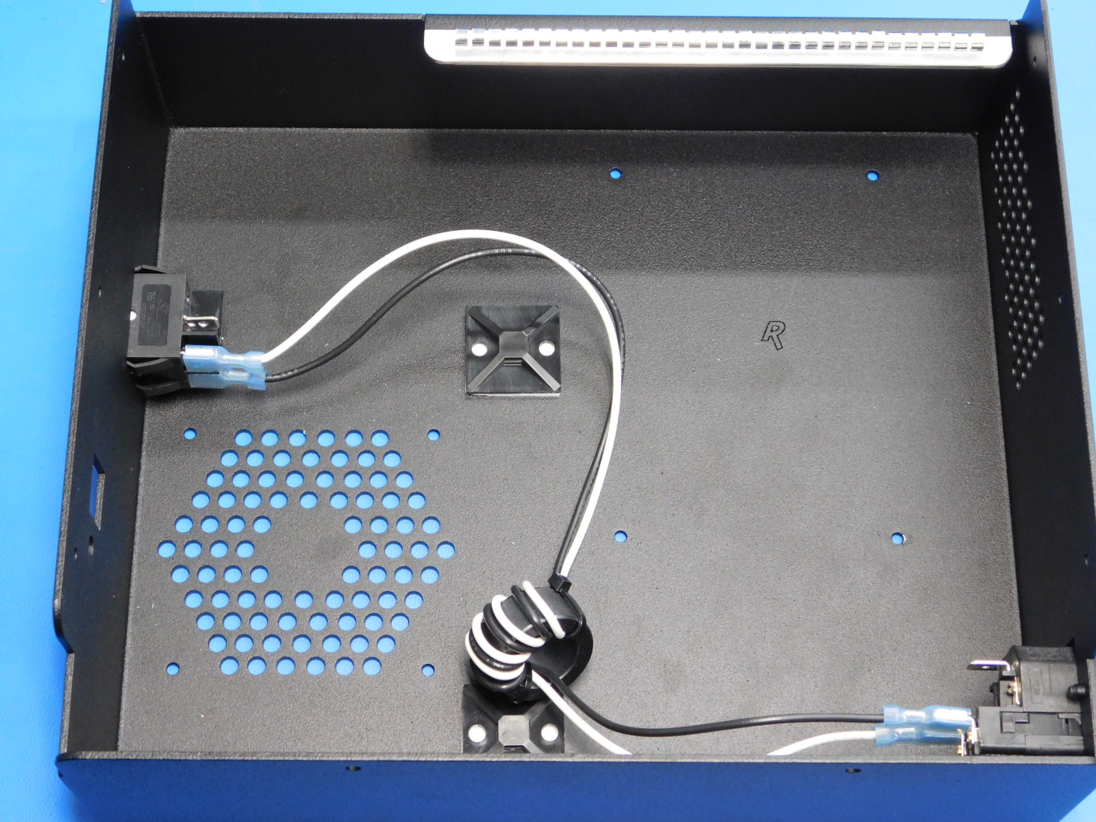
Use two 8 inch zip ties [HD-MS0058] to fasten the Plug to Switch Extension cable and Switch to PS Extension cable to the cable tie downs. Be sure to secure the ferrite and the two wires of the Switch to PS Extension onto the tie down closest to the power entry module. Secure the 4 wires from the Switch to PS Extension and Plug to Switch Extension onto the tie down closest to the switch (see picture).
Cut the excess off the zip ties flush with the latch.

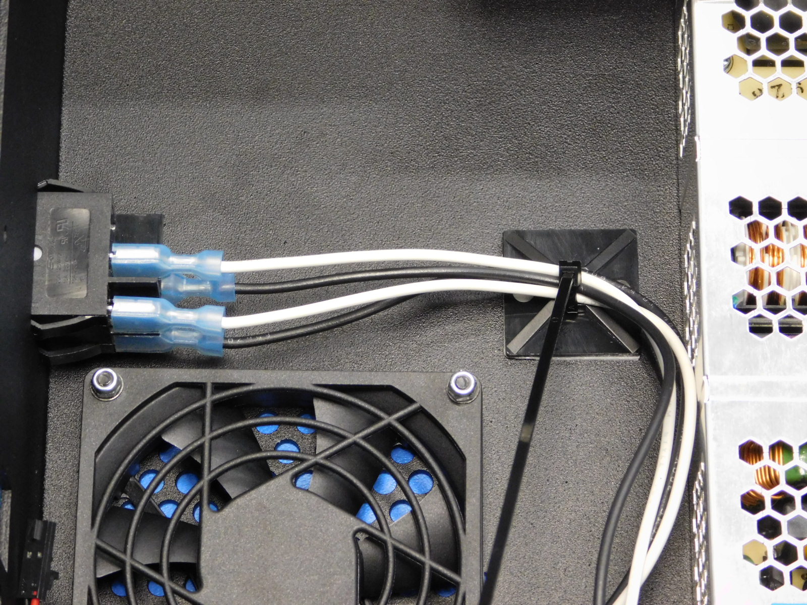
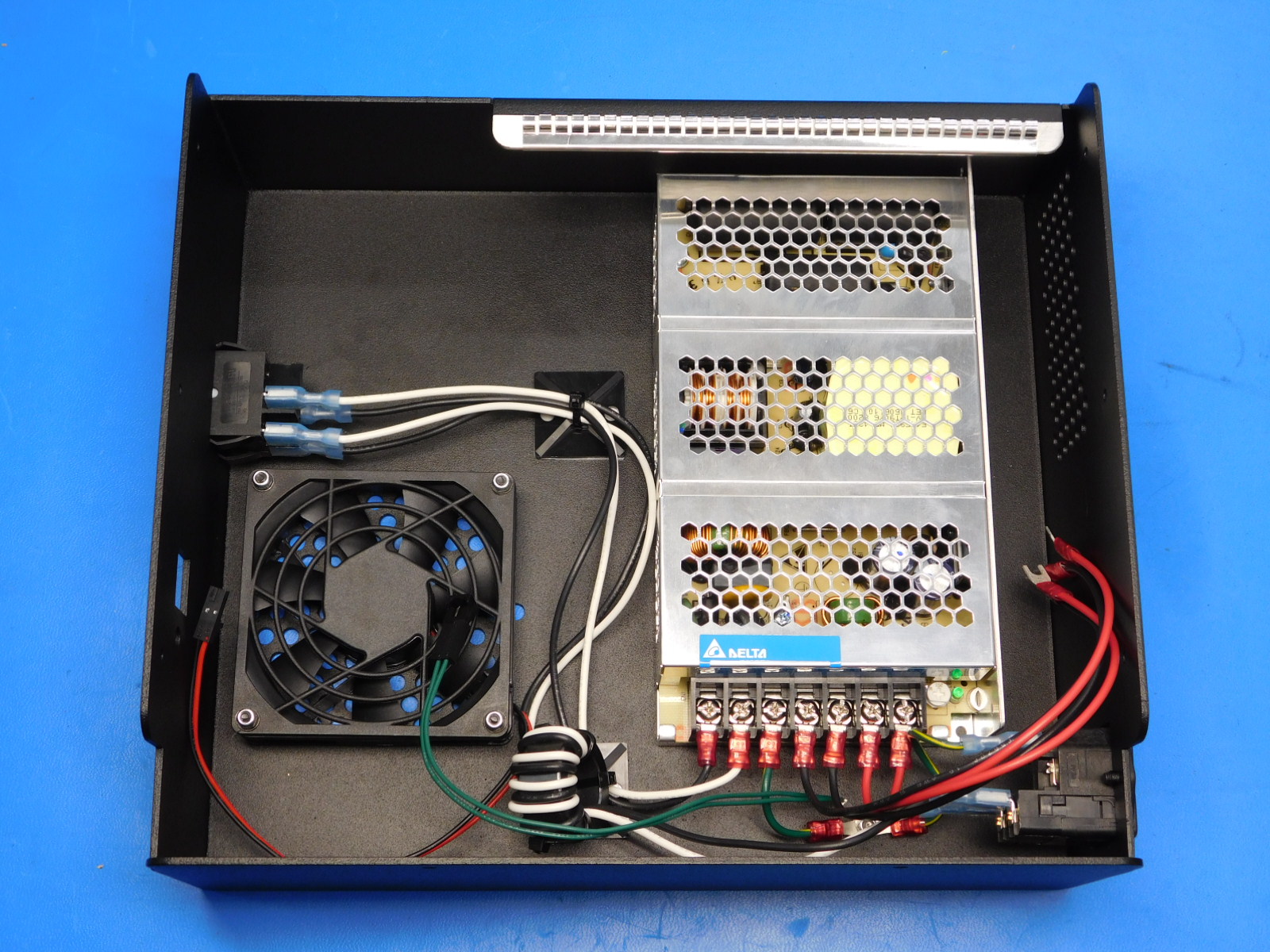
Check your assembly and verify that it matches the picture shown at right.
Connect a power cable to the receptacle
Before flipping the power switch, ensure the fork terminals exiting the PSU are kept separate
Flip the power switch to the on position and ensure the following:
The power LED is lit on the PSU
The rocker switch lights up when in the on position and turns off when in the off position