Open HardwareAssembly Instructions
Guides for installation and assembly of the LulzBot line of products made by Aleph Objects, Inc.
Guides for installation and assembly of the LulzBot line of products made by Aleph Objects, Inc.
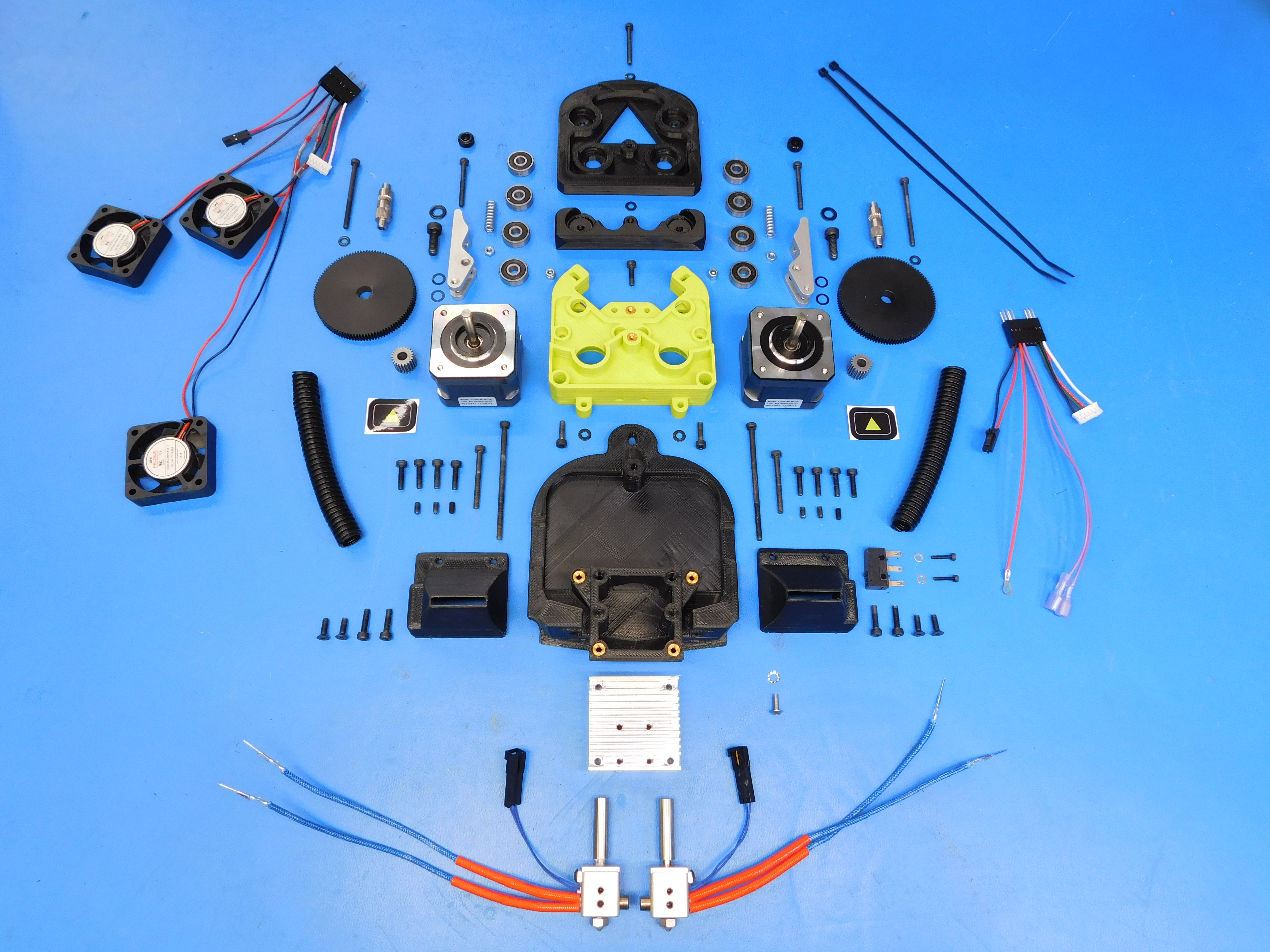
Gather the required materials:
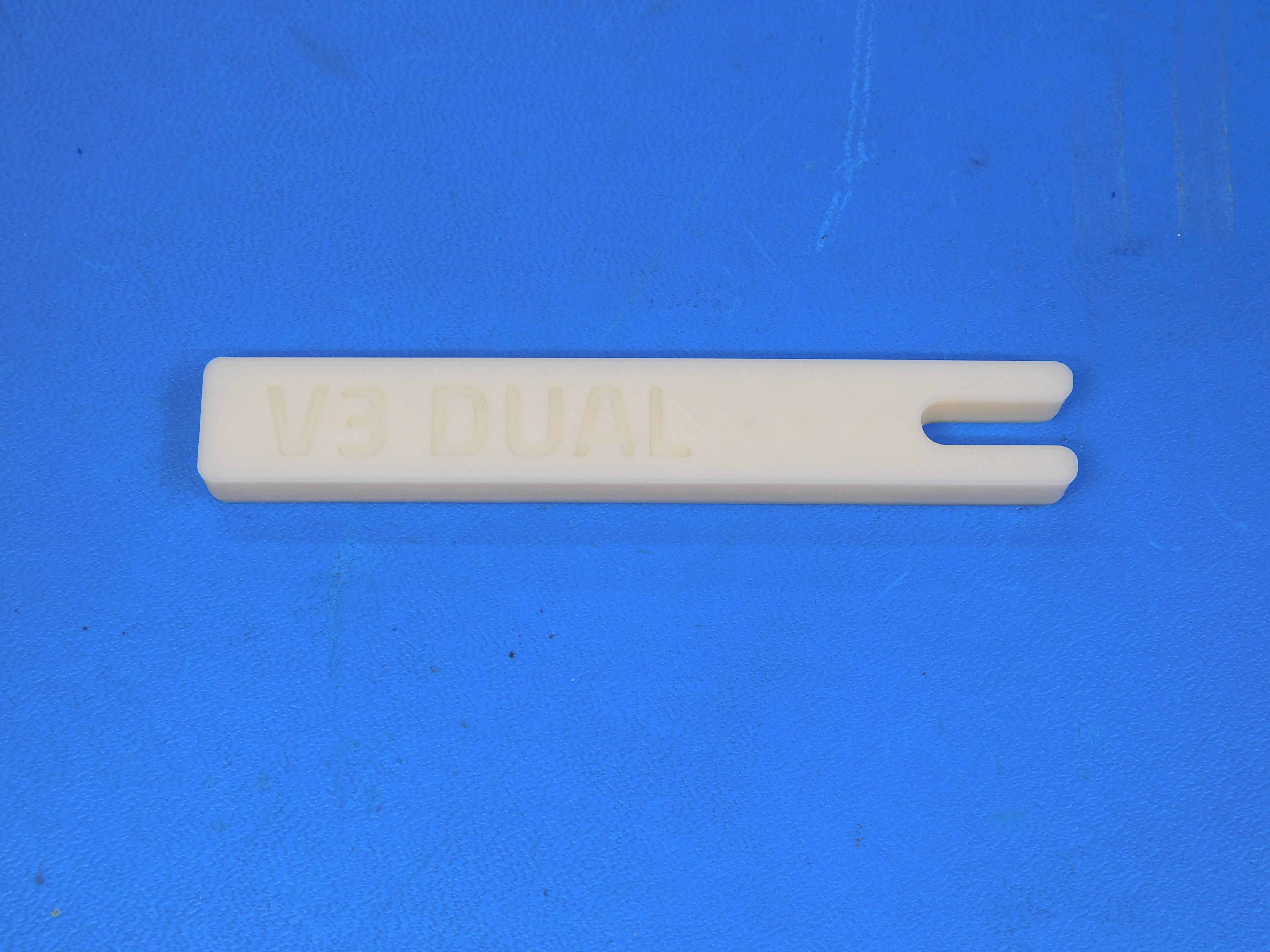
Special tool: 8.5mm spacer
Put the thermal inserts into the printed parts. For more information on inserting printed parts see this tutorial: https://www.lulzbot.com/learn/tutorials/heat-set-inserts-tips-and-tricks
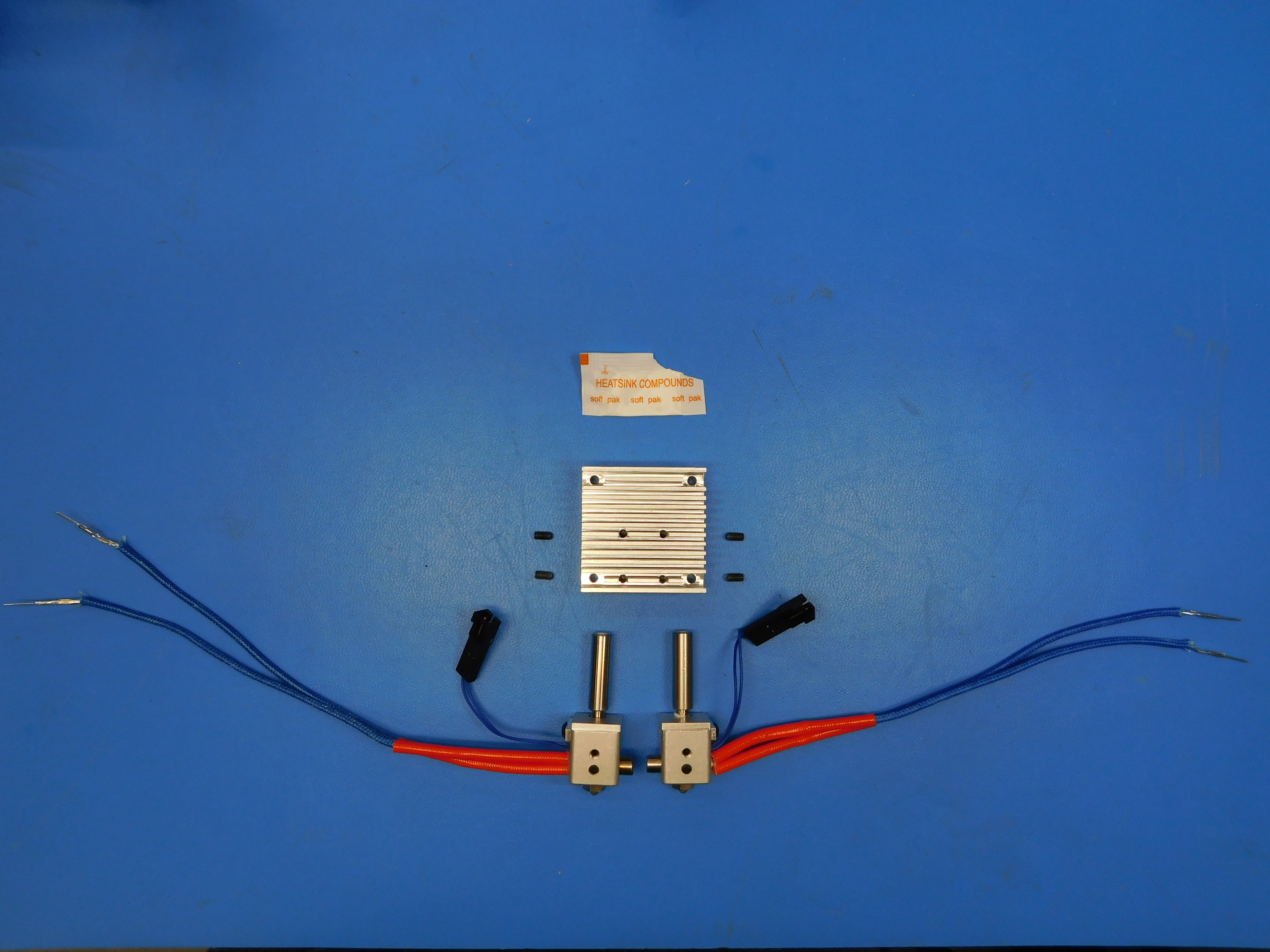
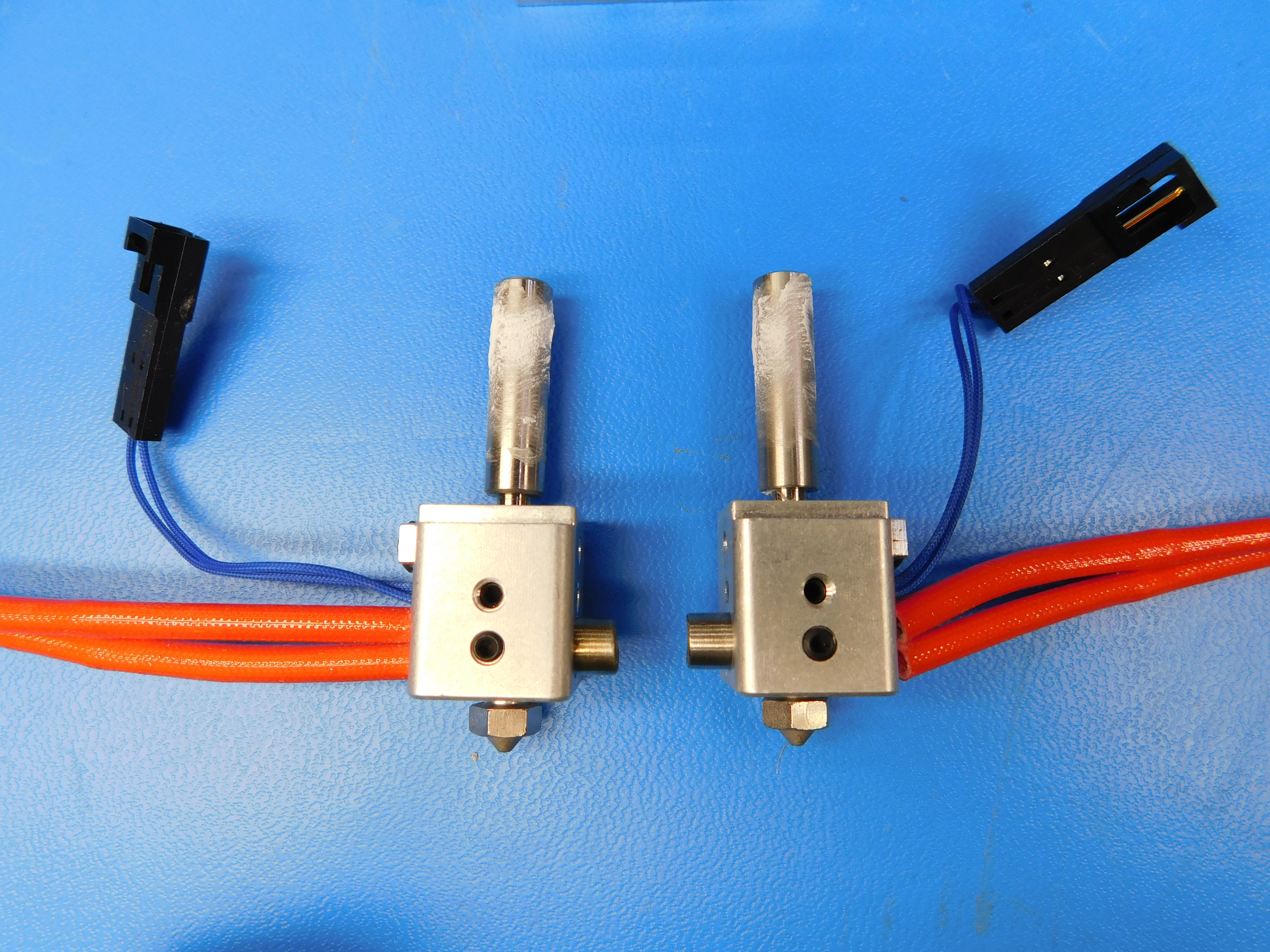
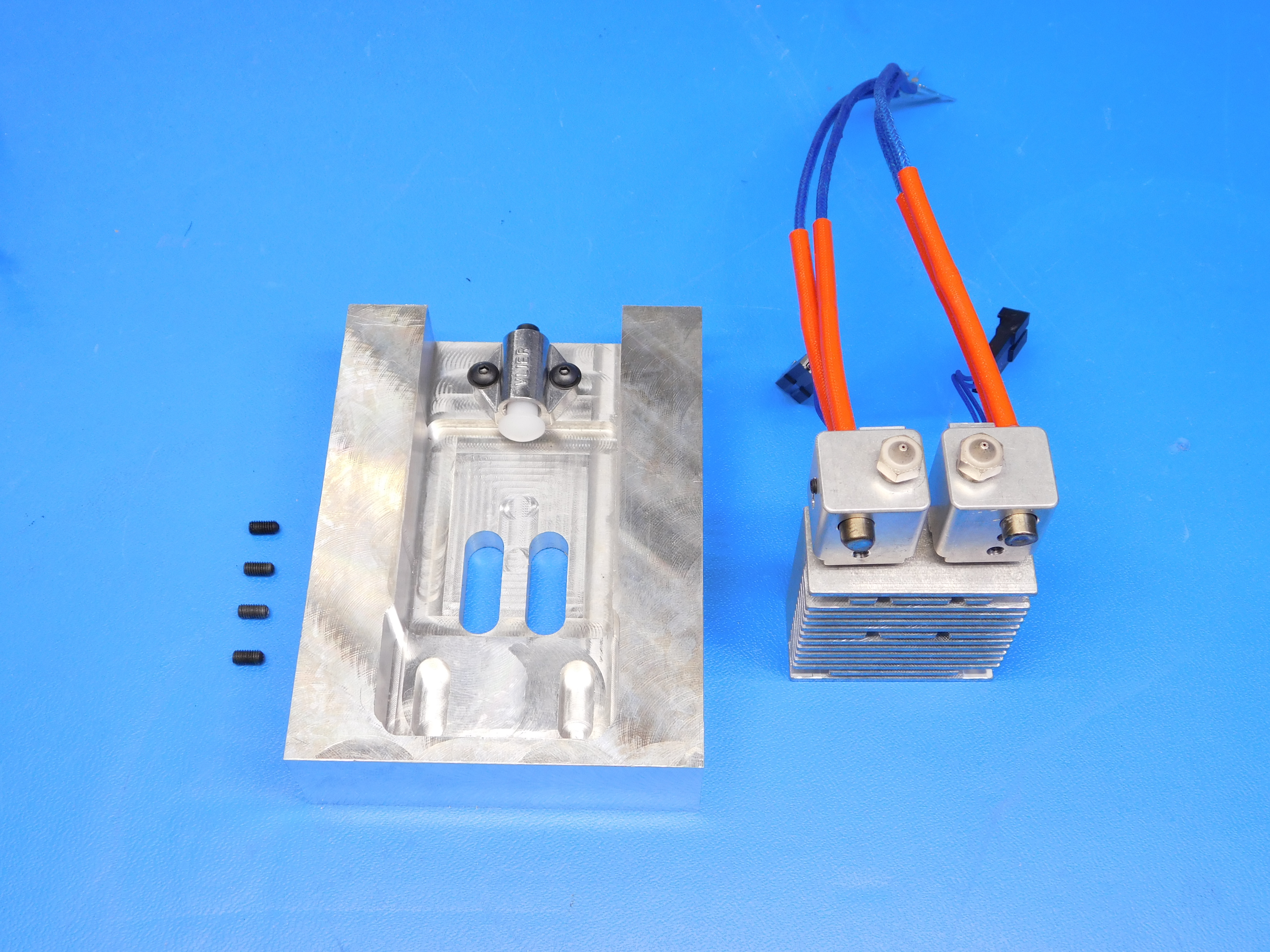
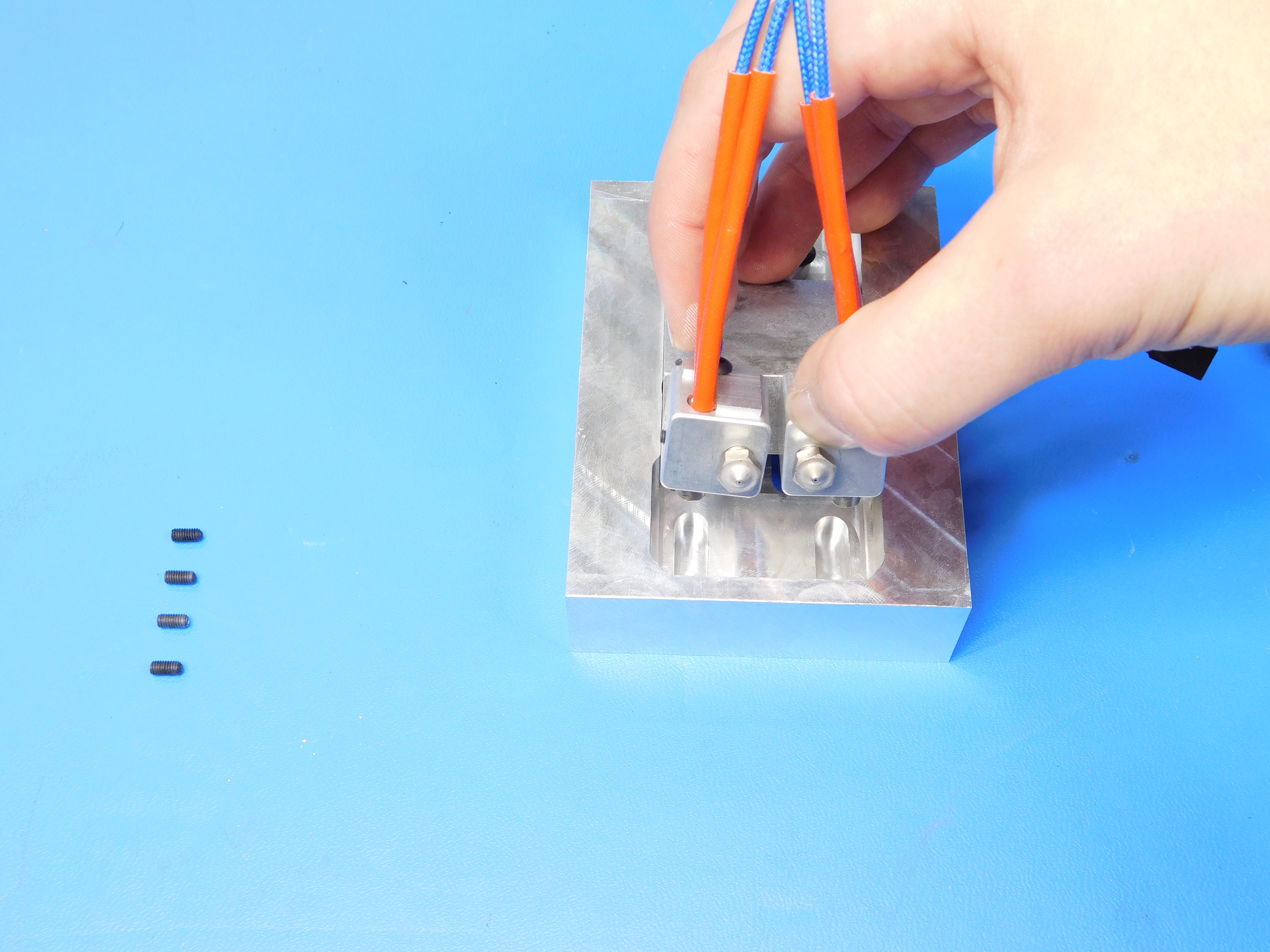
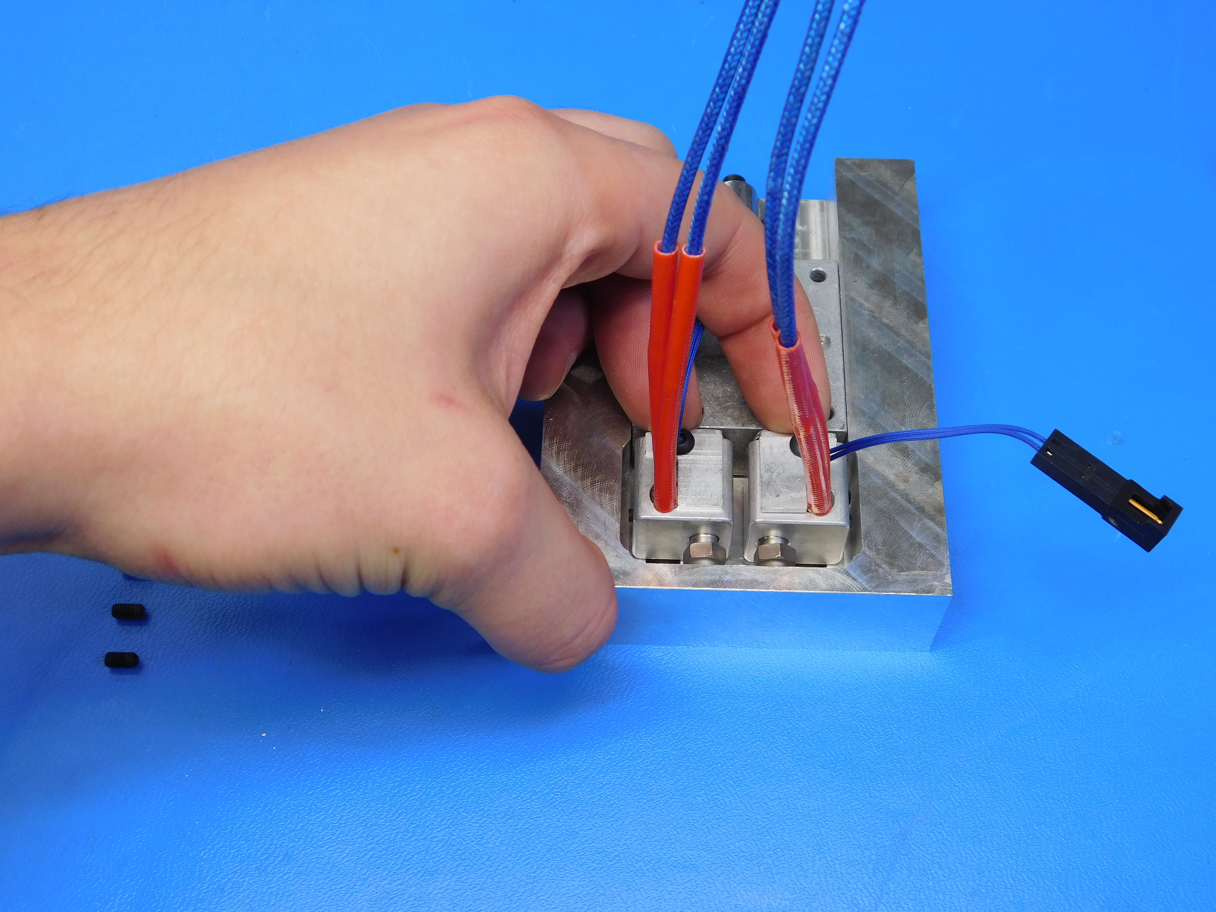
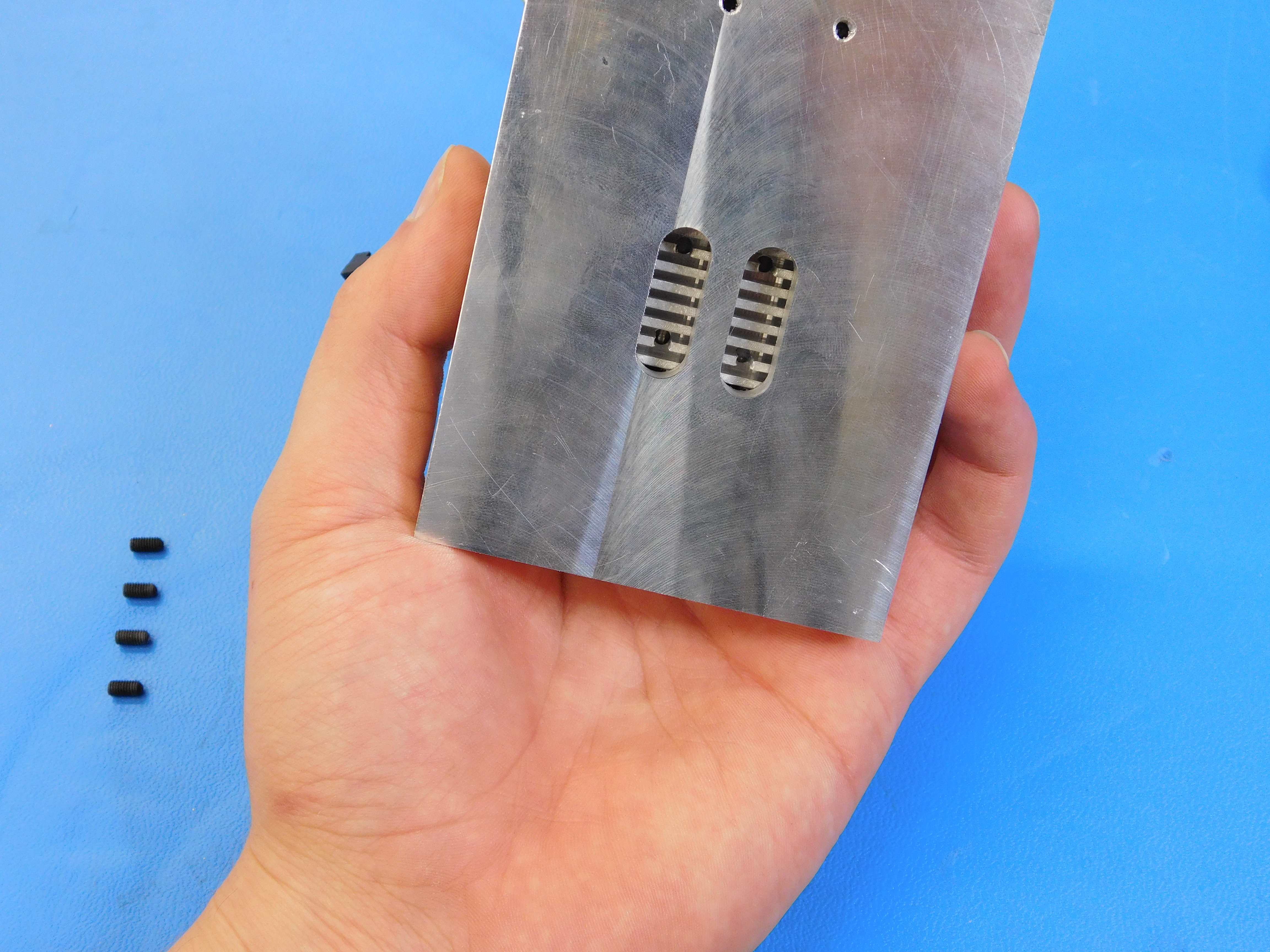
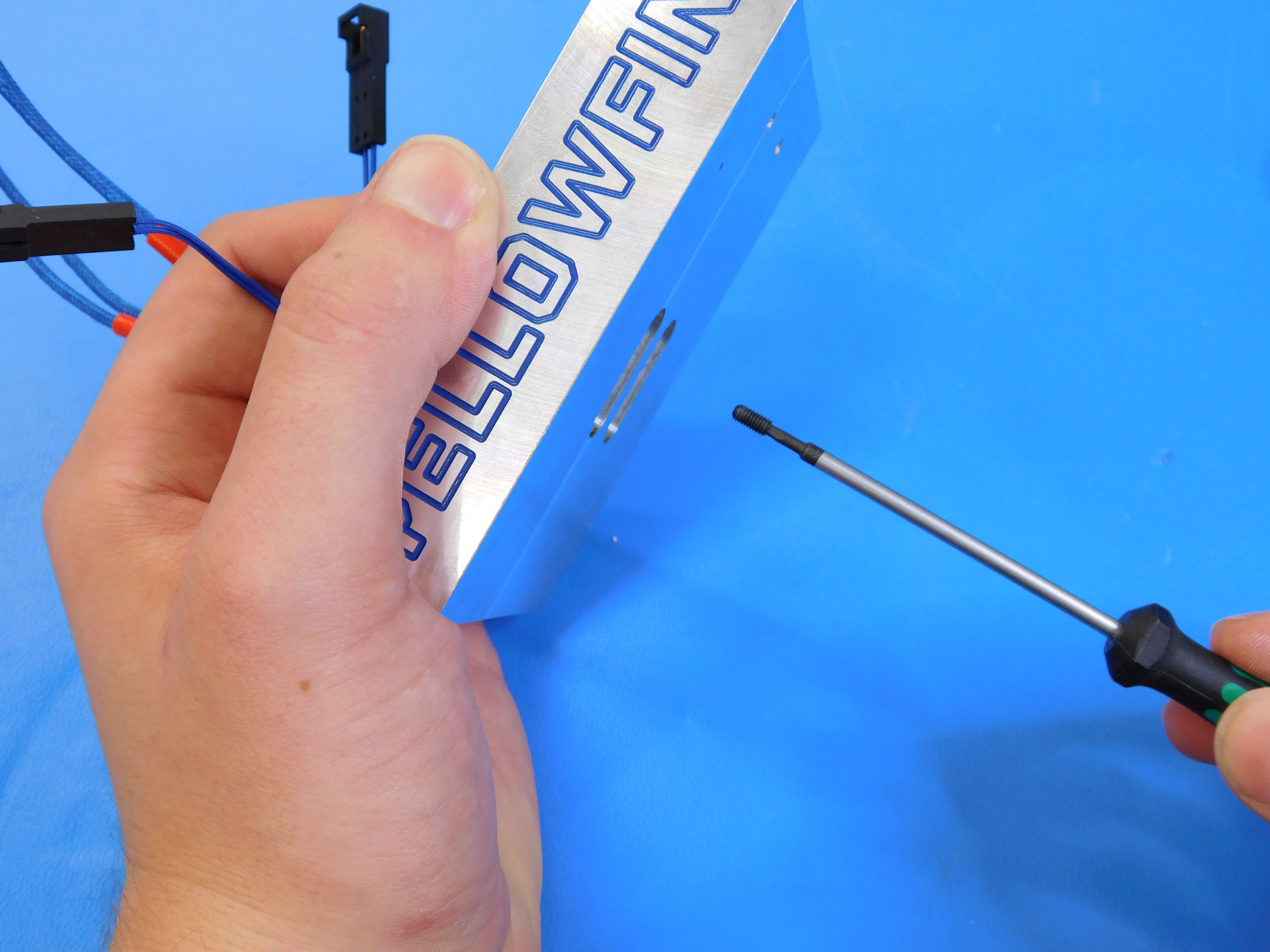
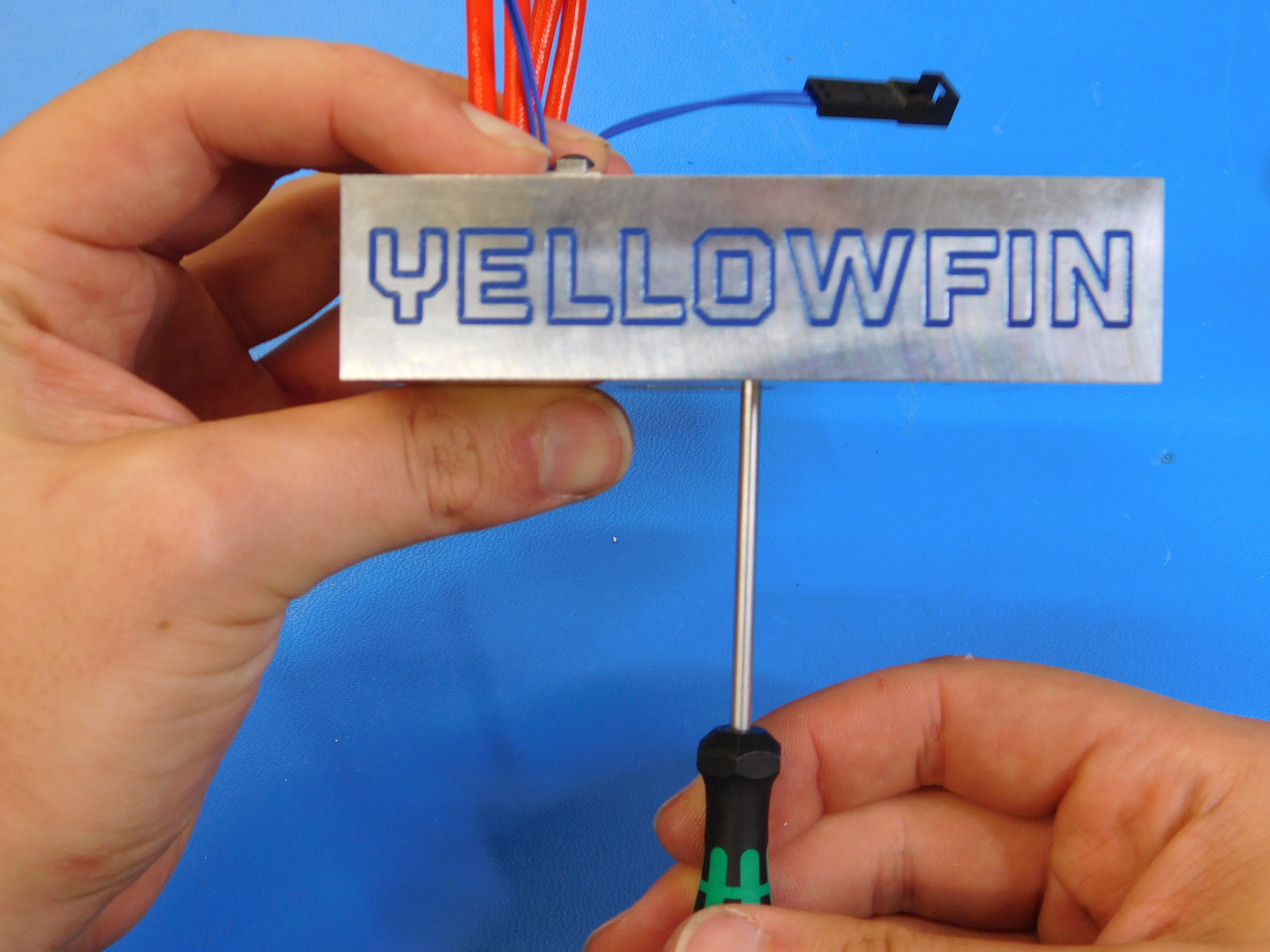
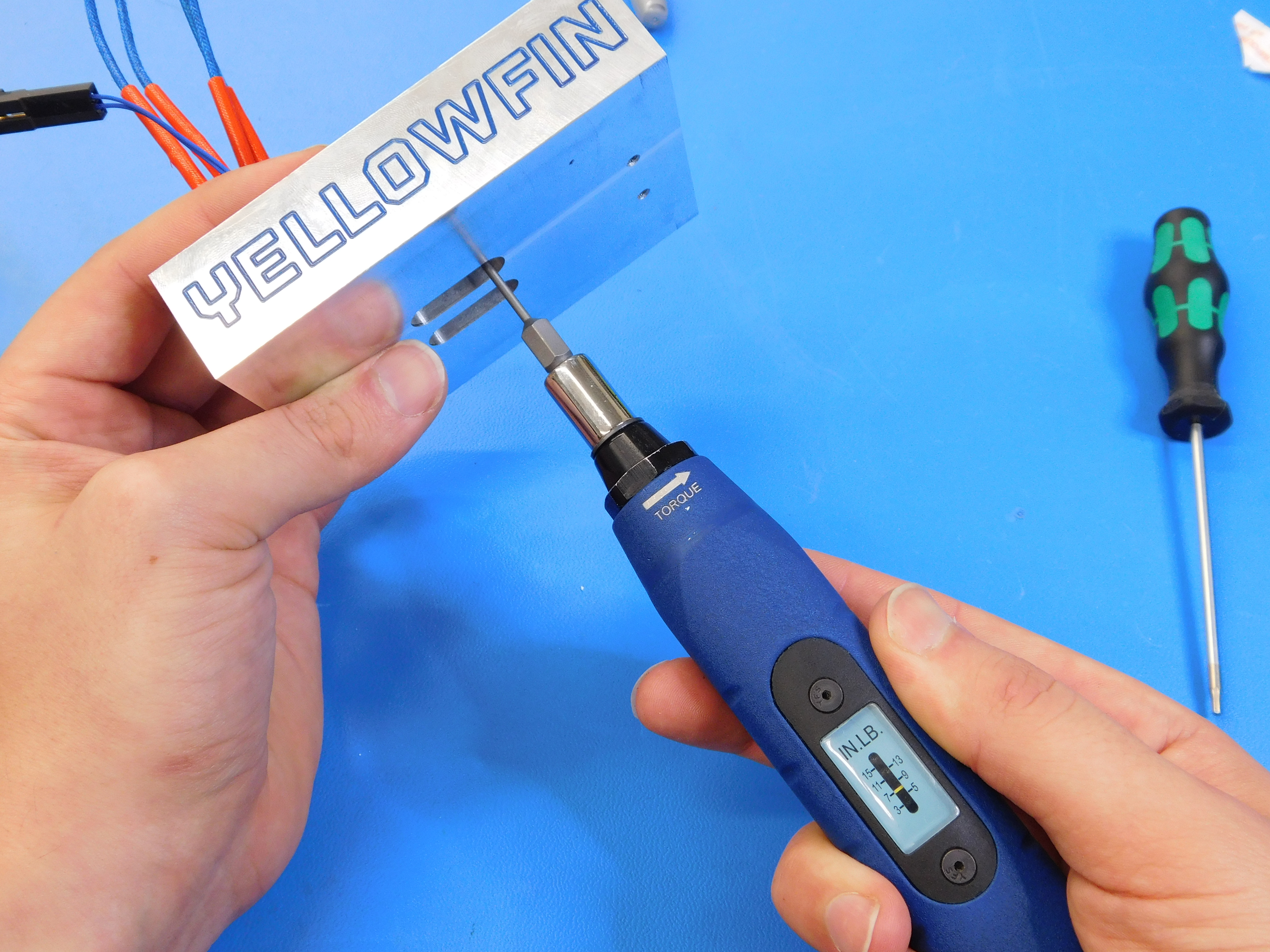
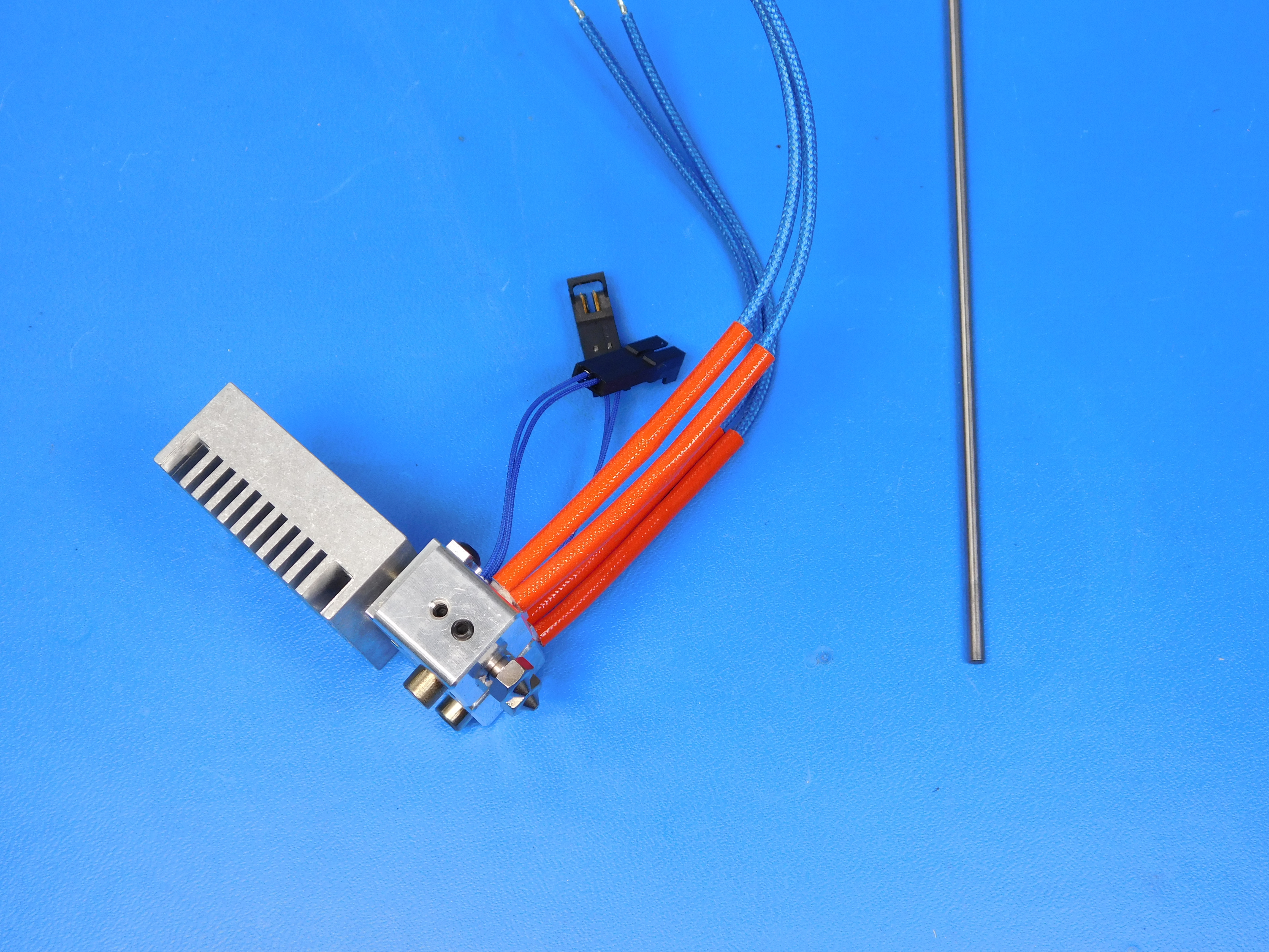
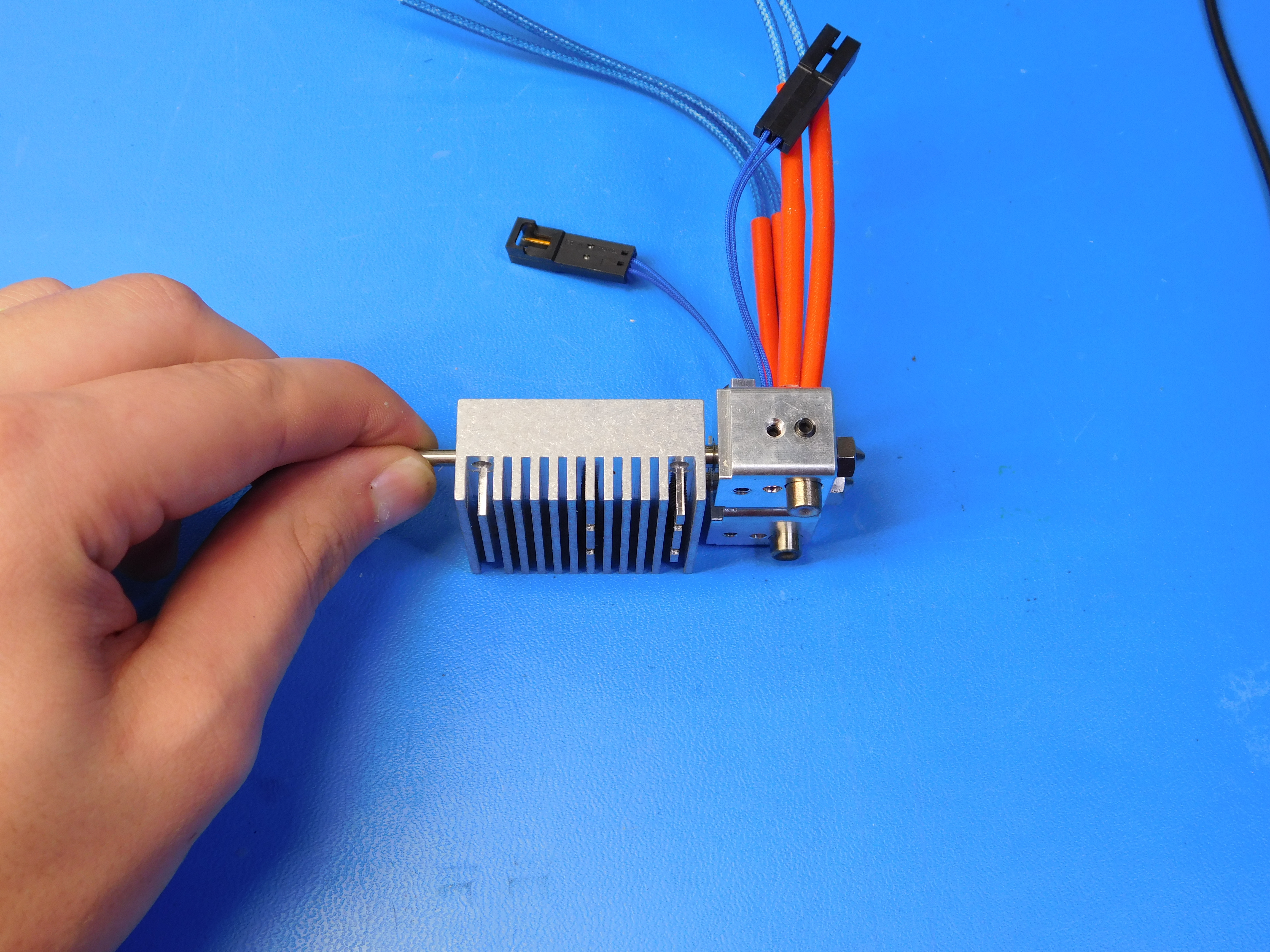
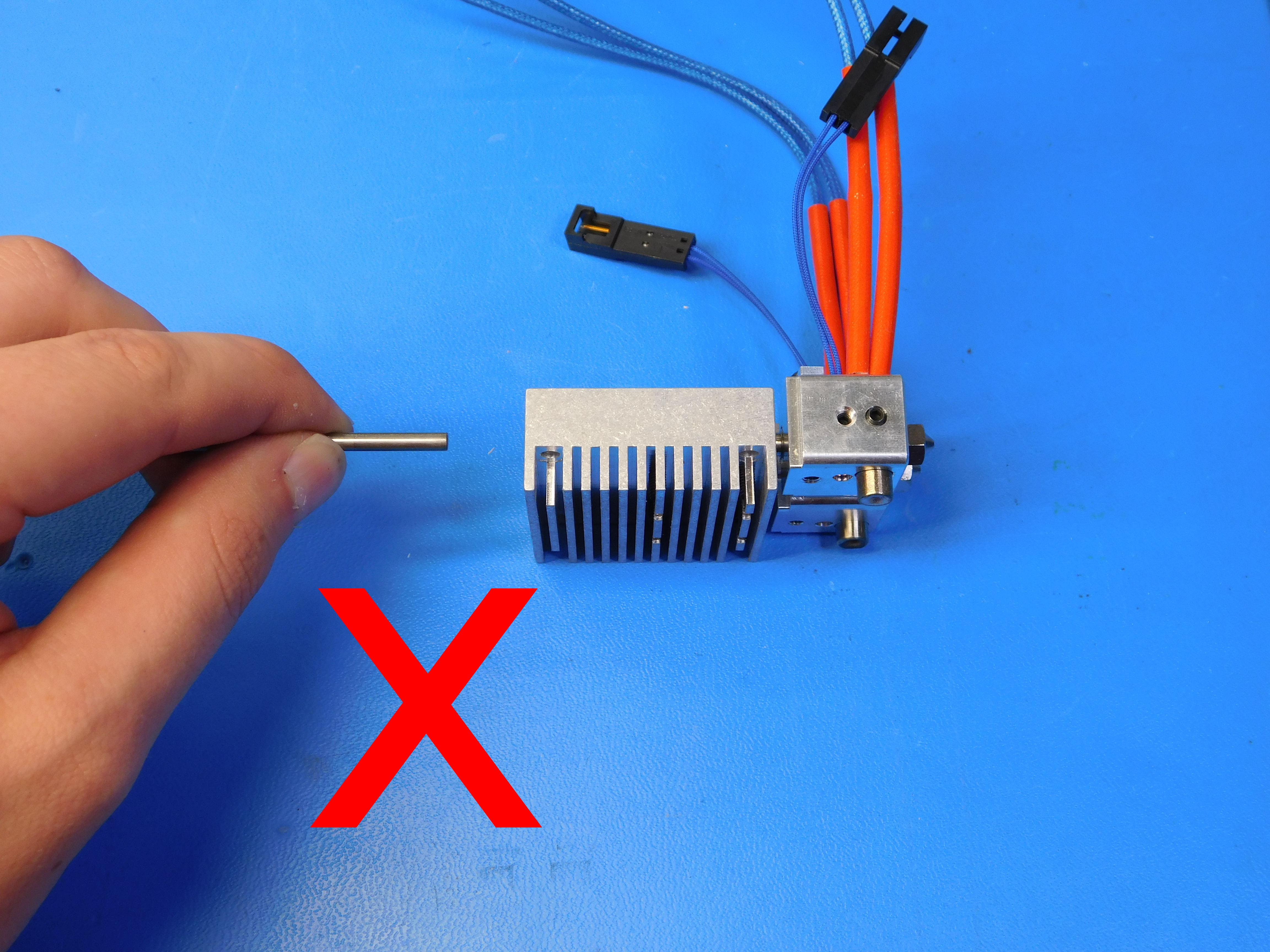
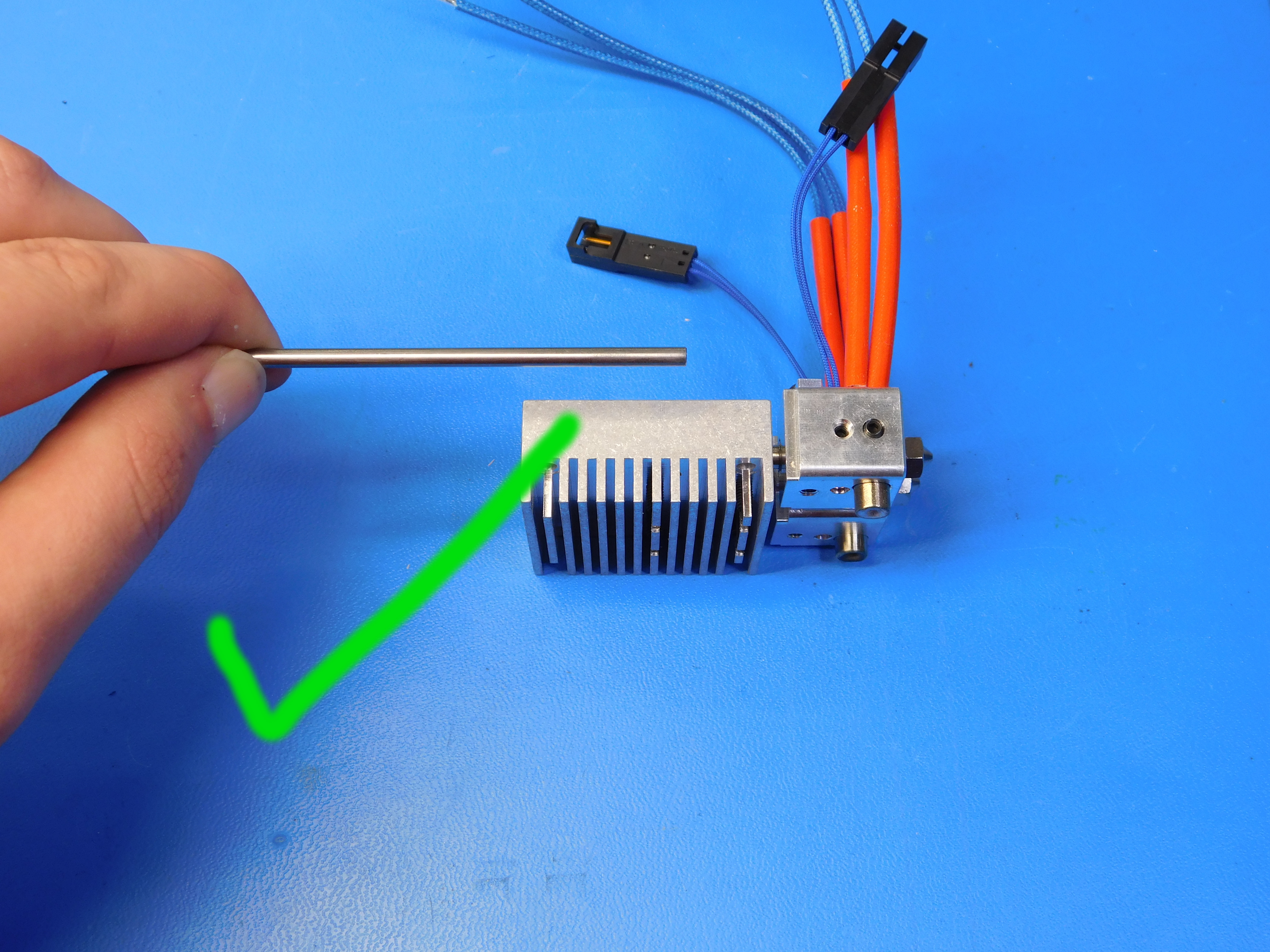
Squeeze a little thermal paste [PP-MP0162] onto the heat break [PP-MP0171] and spread it evenly across the cylindrical surface. Use the jig to make sure the heaterblocks are aligned with each other and that the nozzles are the same distance from the heat sink. Torque the four M3 x 6 set screws [HD-BT0012] to seven in*lbs. Push a 3mm rod into the heat sink gently until it stops. If the rod does not pass all the way to the nozzle, put a red tag on the heat sink and use a different heat sink.
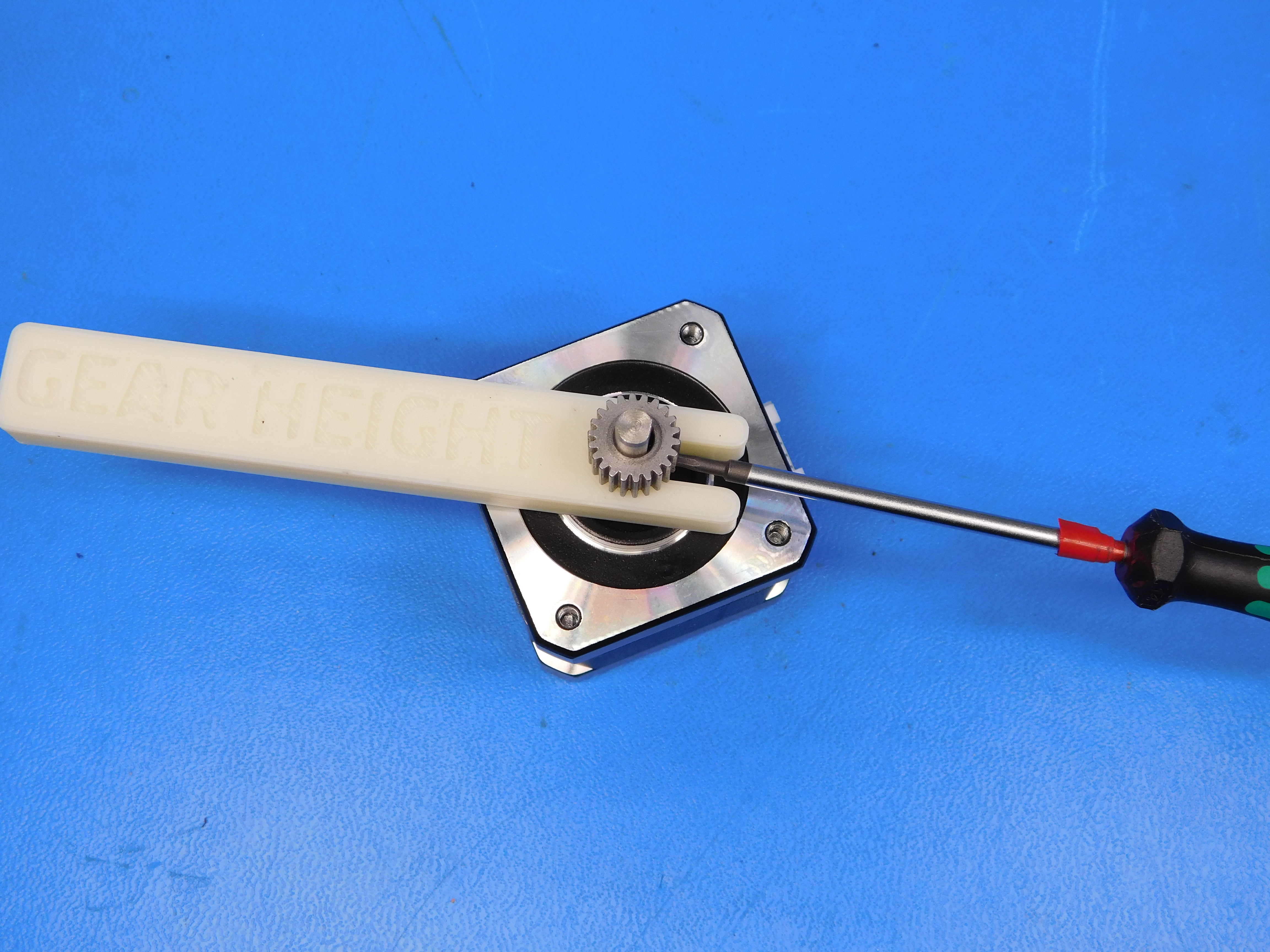
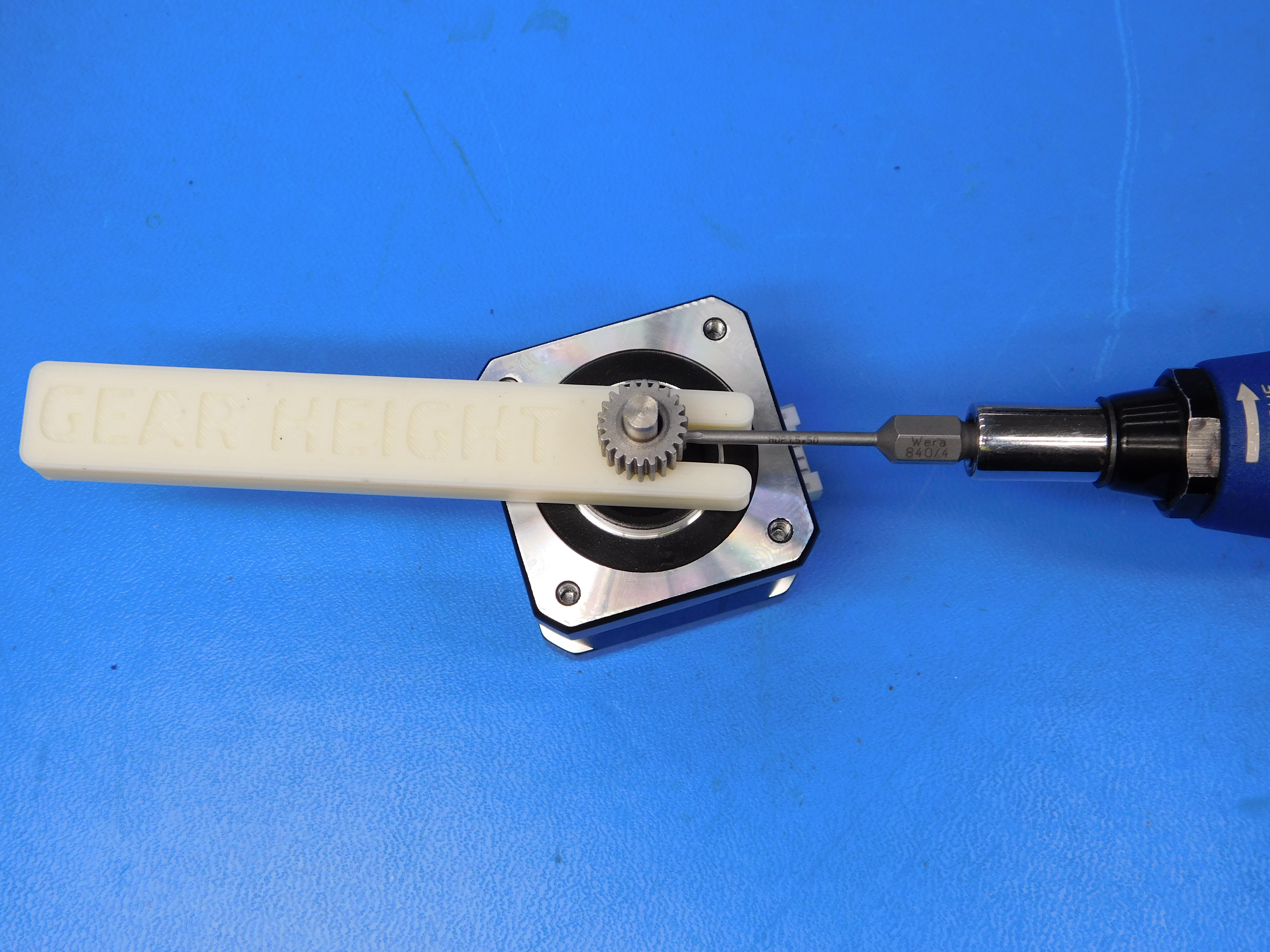
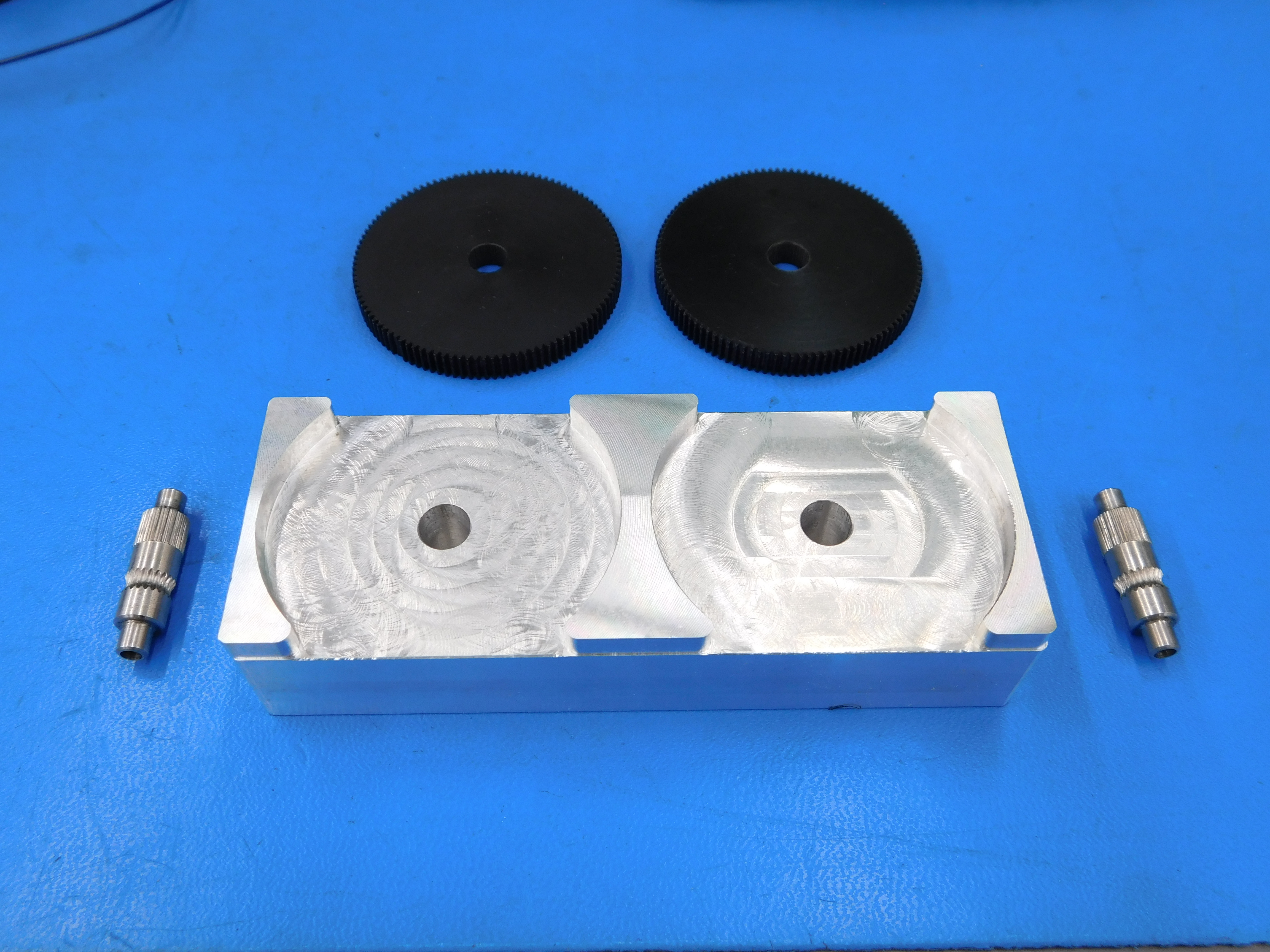
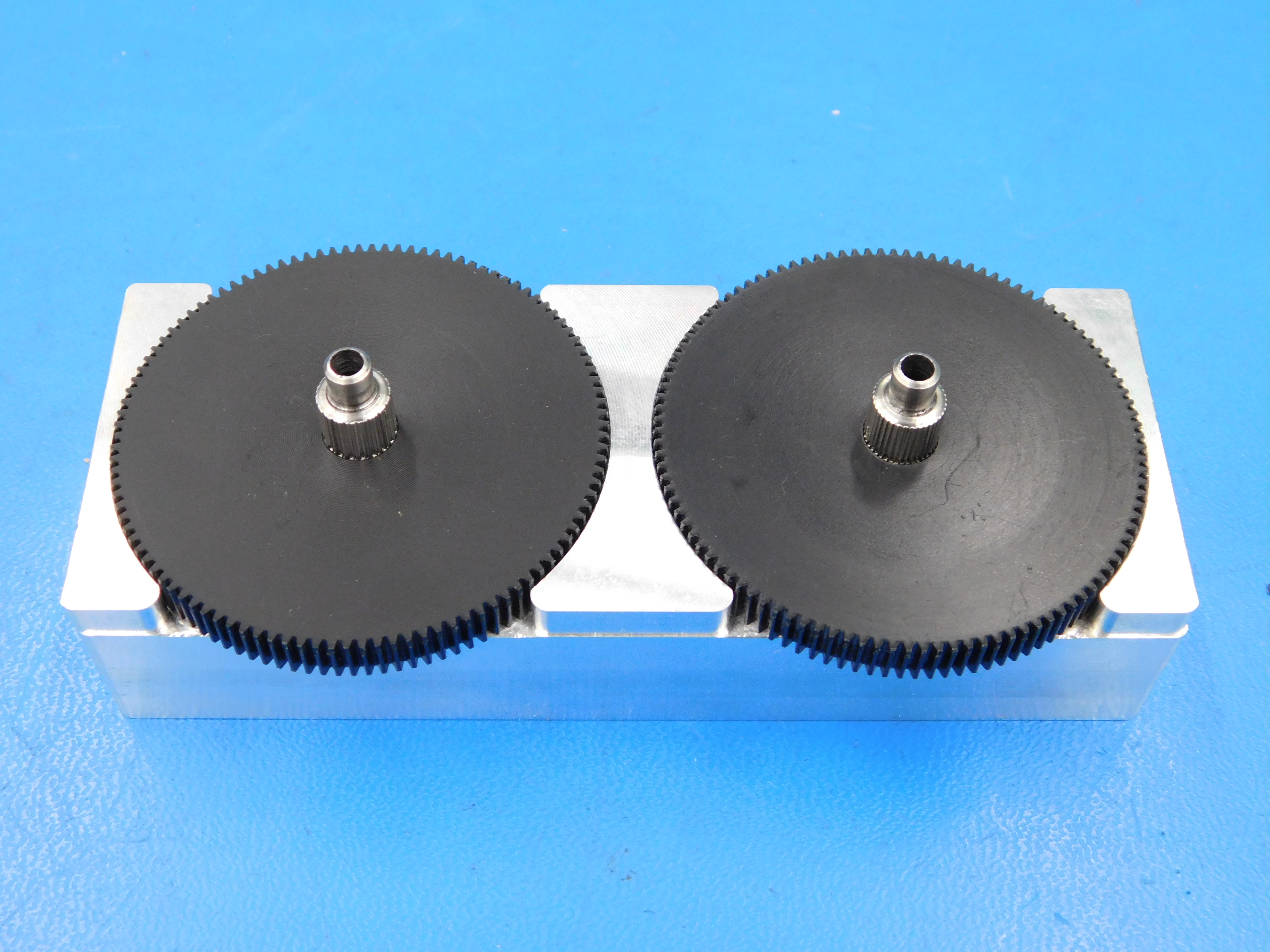
Using the spacer jig, install the small gear [PP-MP0282] onto the motor shaft [EL-MT0040] with the M3x3 set screw that comes with the pinion gear on the flat side of the shaft. Torque the set screw to 5 in * lbs.

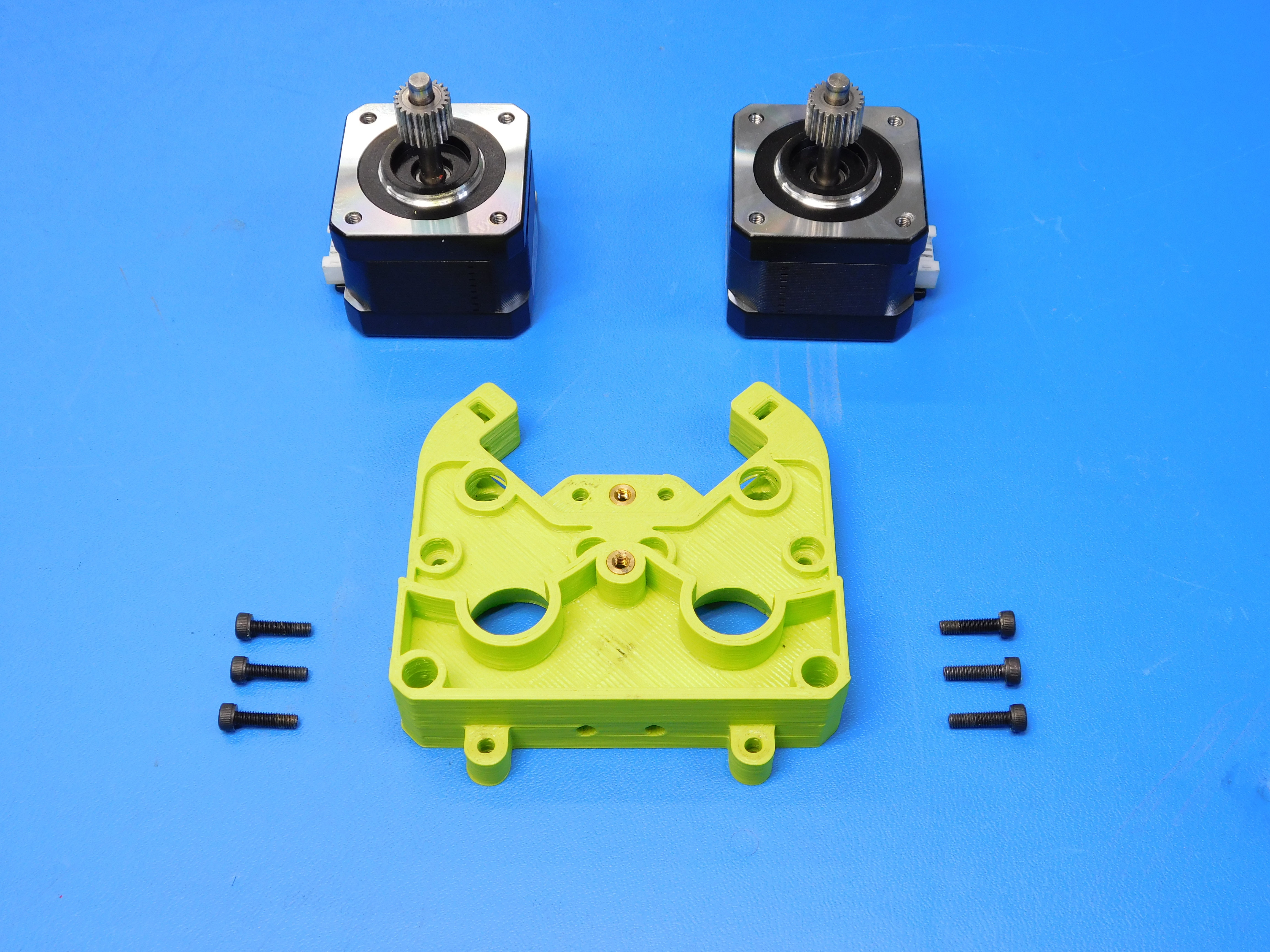
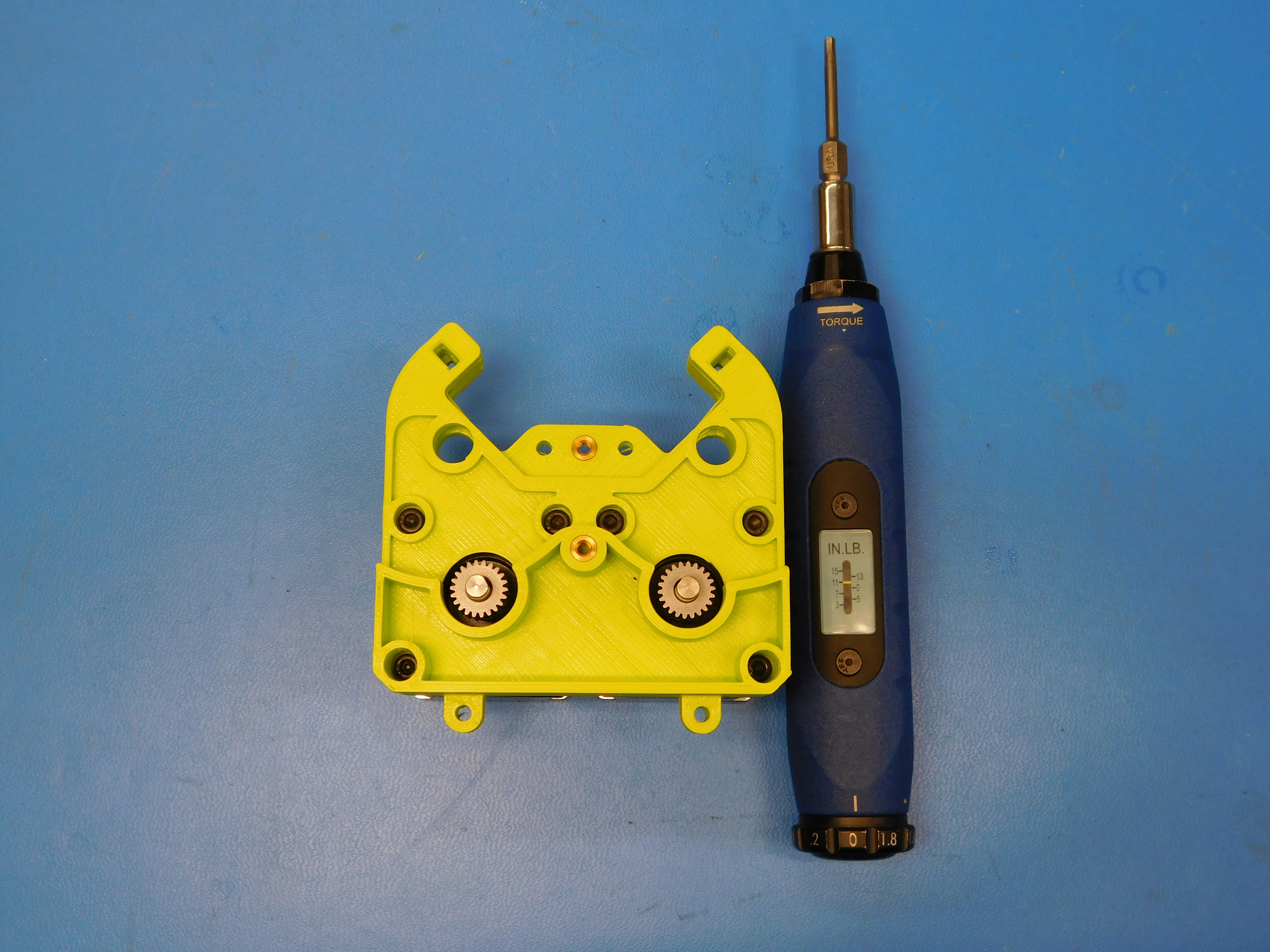
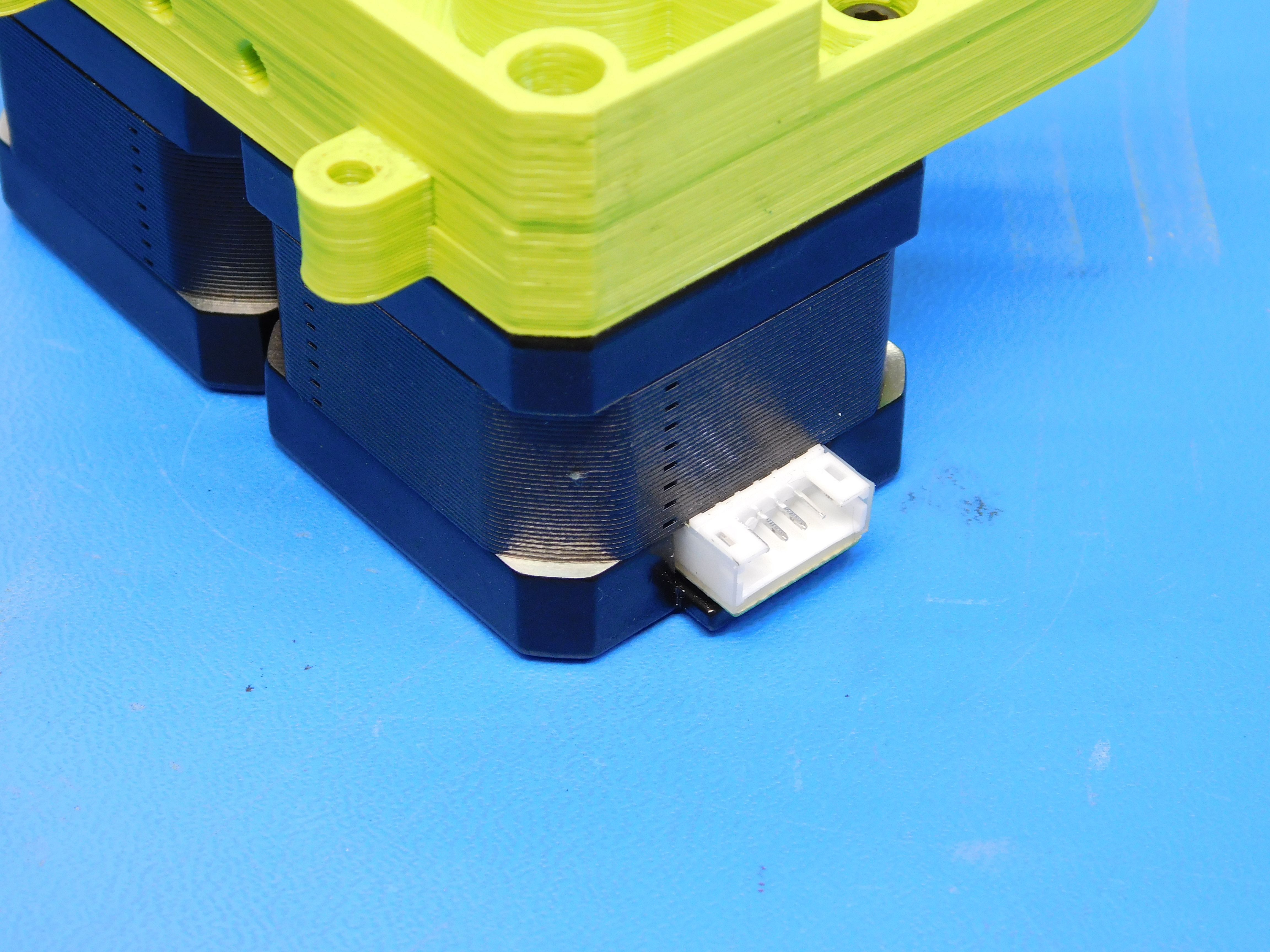
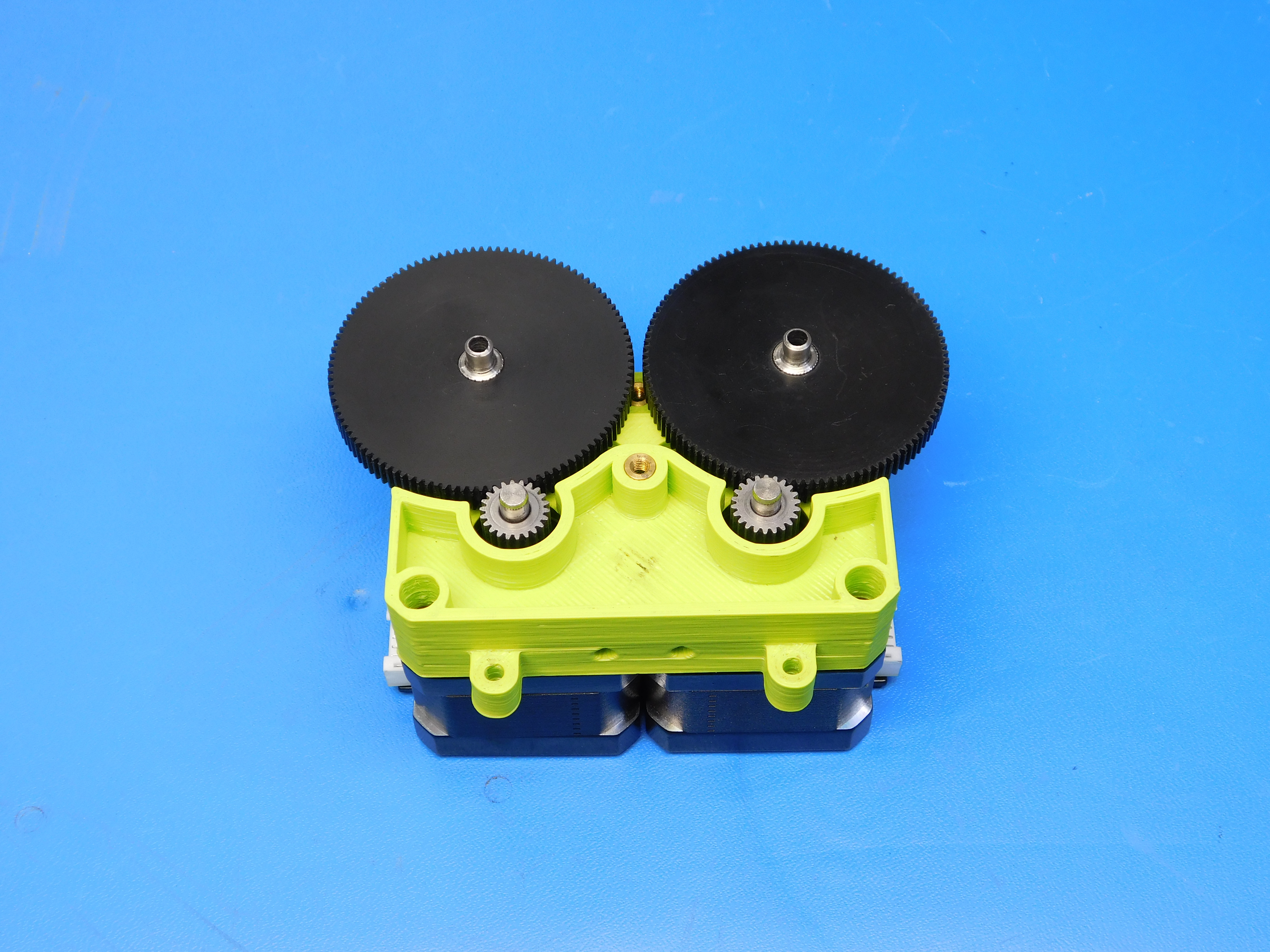
Install the two motor-gear assemblies into the inserted extruder body [PP-IS0037] using six M3 x 12 SHCS [HD-BT0039]. Torque the motor fasteners to 8 in * lbs. Make sure the motor connectors are facing outwards.
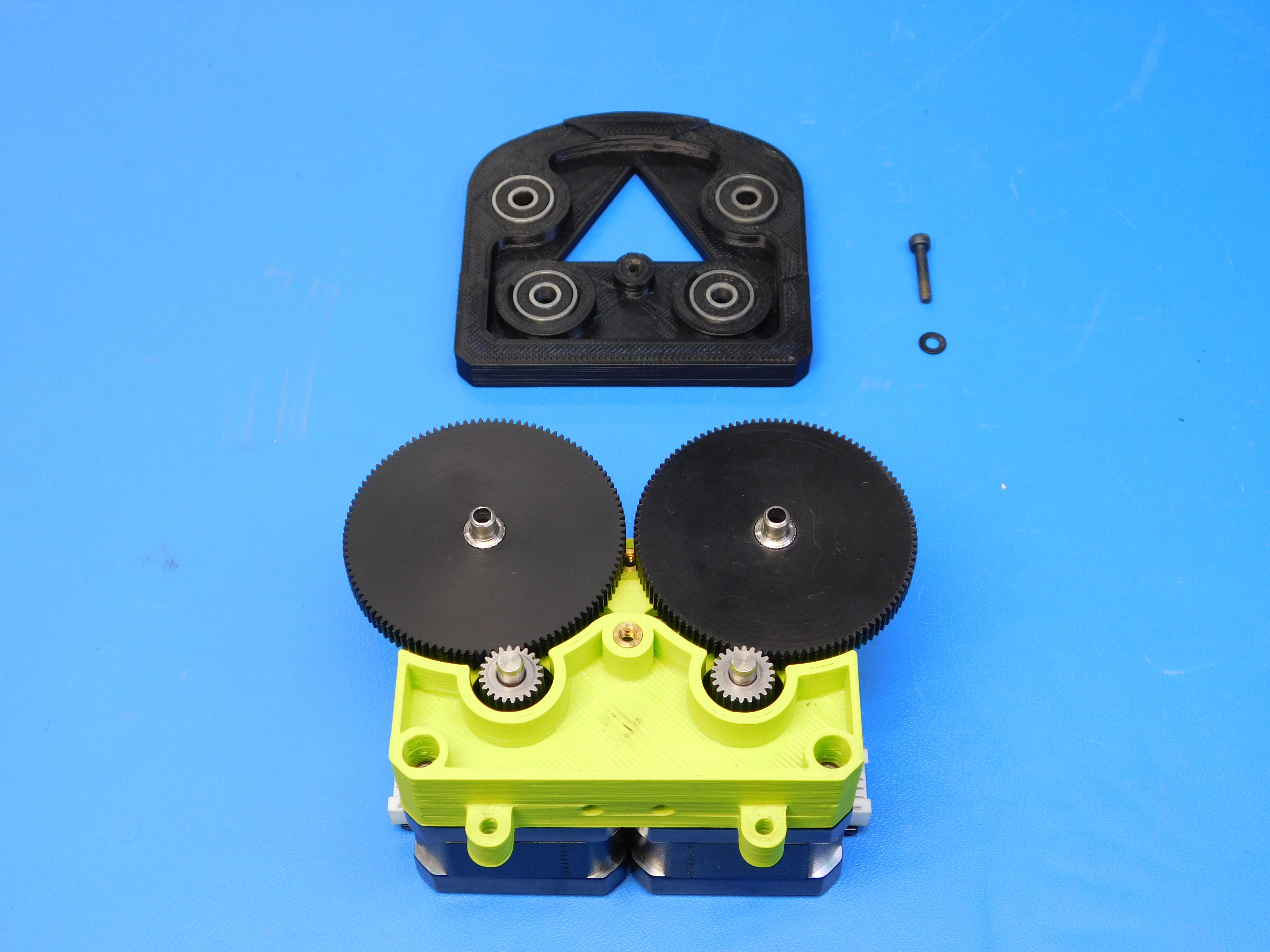
Use the arbor press to press in four bearings [HD-MS0411] into the cover plate [PP-GP0291].
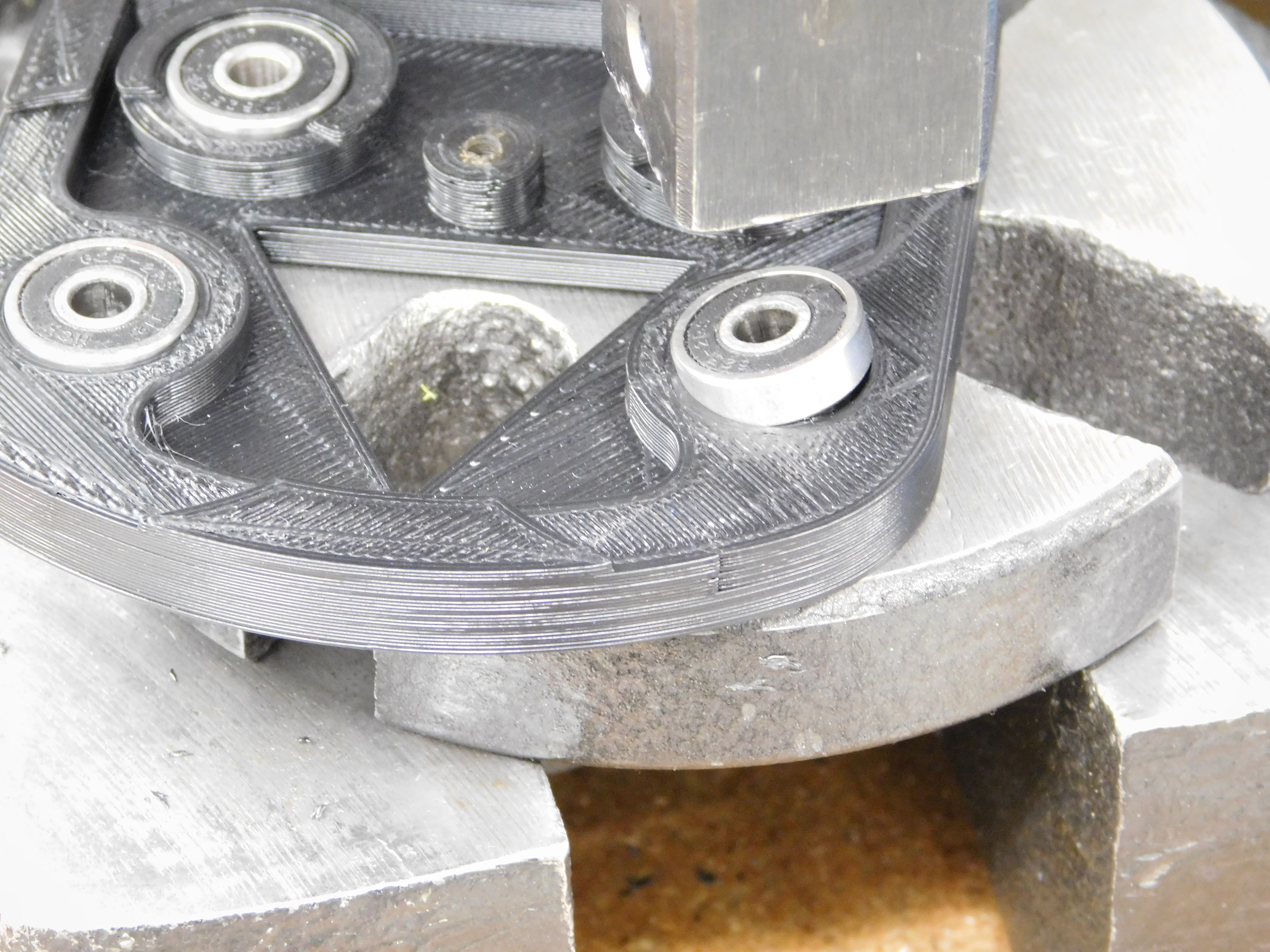
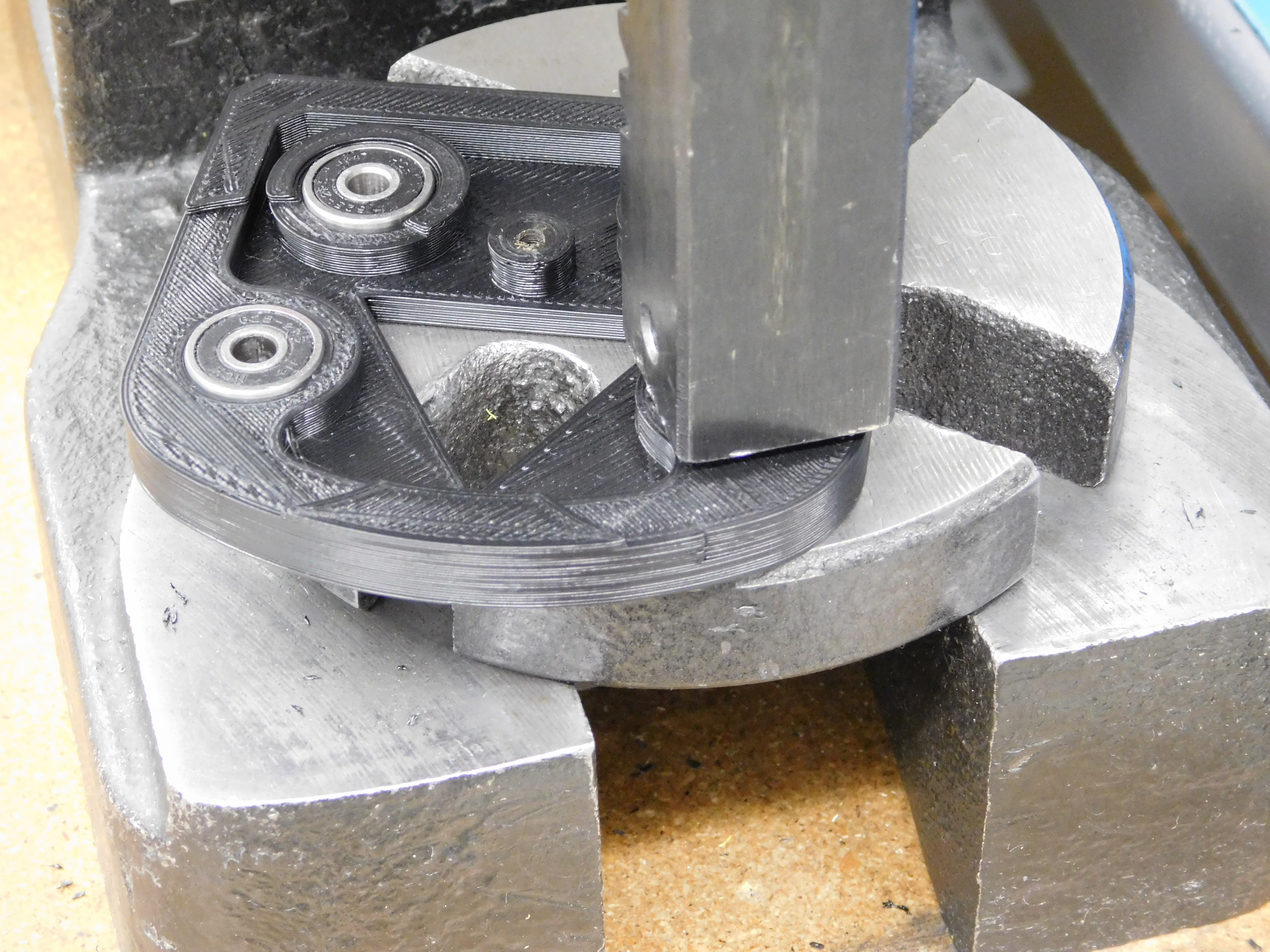
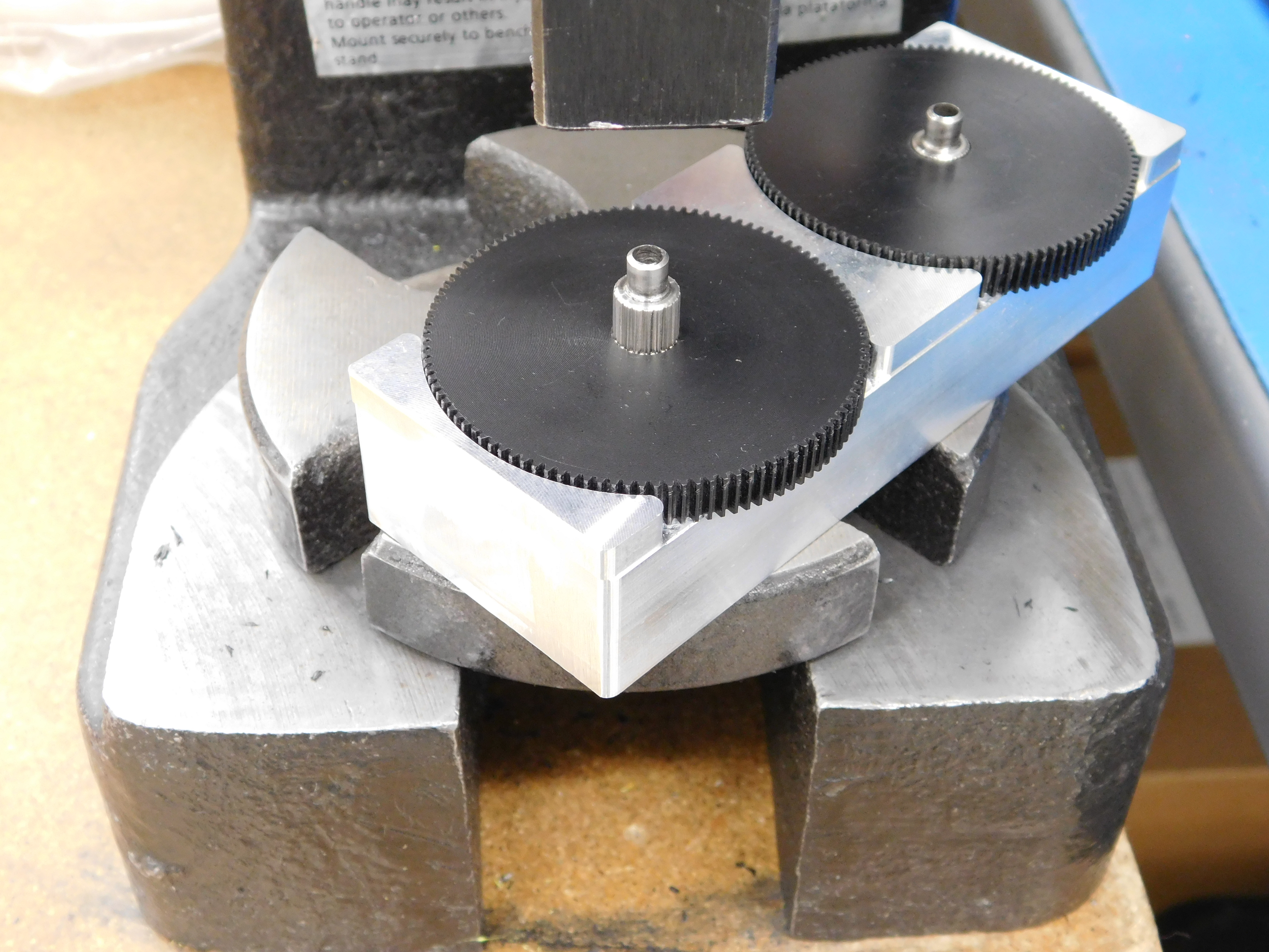
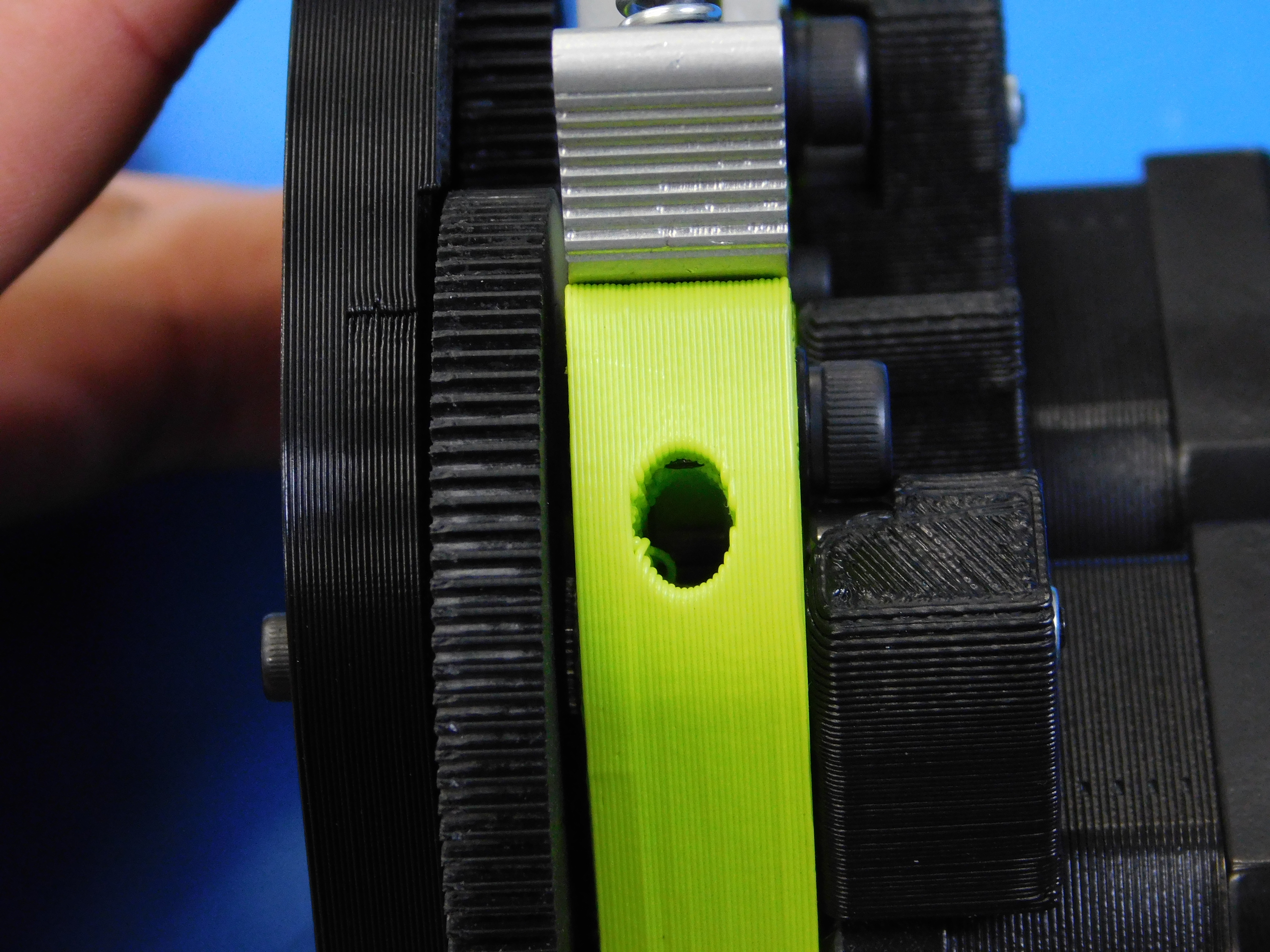
Press the hobbed shaft [PP-MP0173] into the large gear [PP-MP0183]. Use the alignment jig to put the middle of the gear in the middle of the from rolled section of the hobbed shaft. Press gently until it stops.
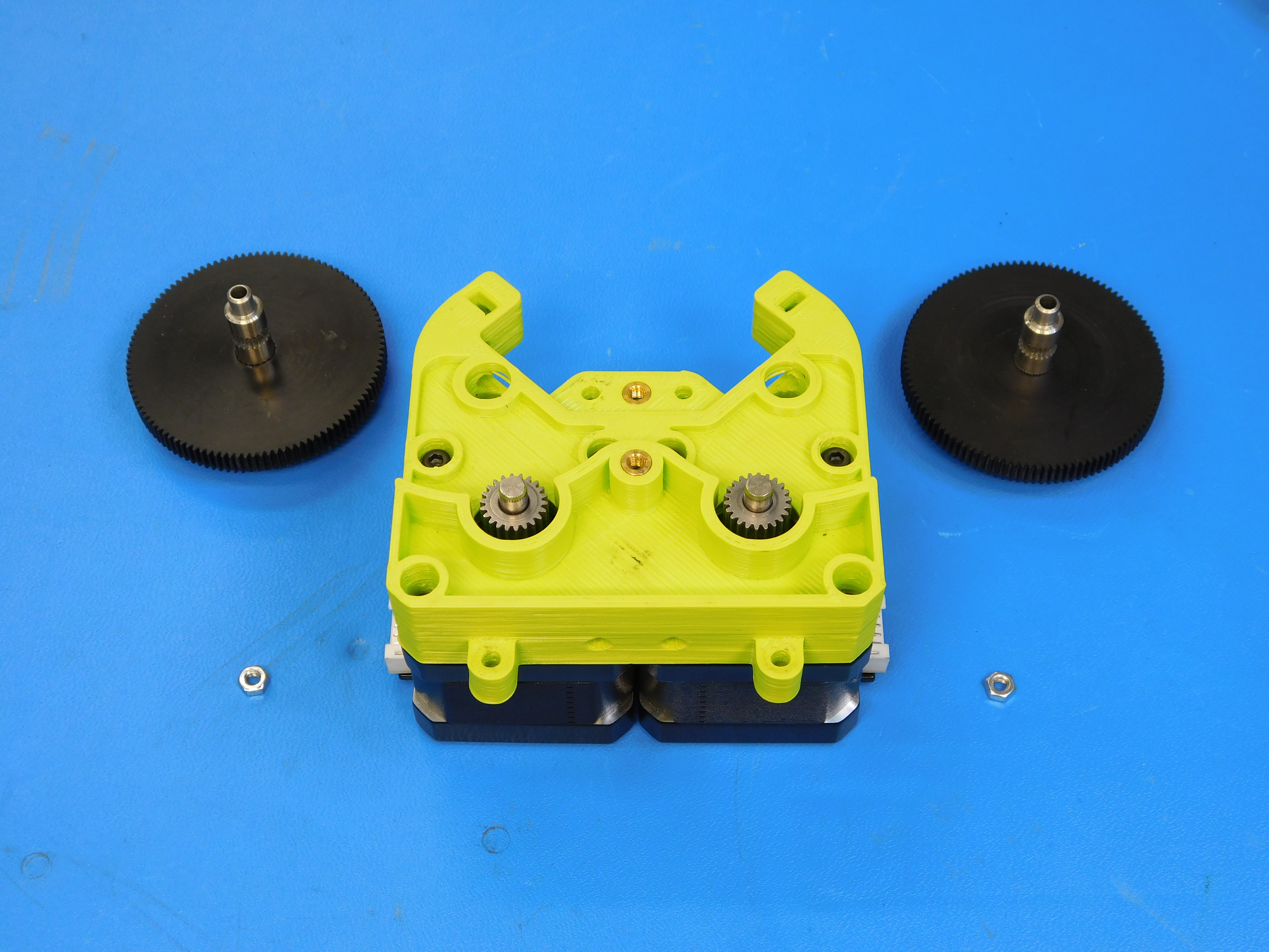
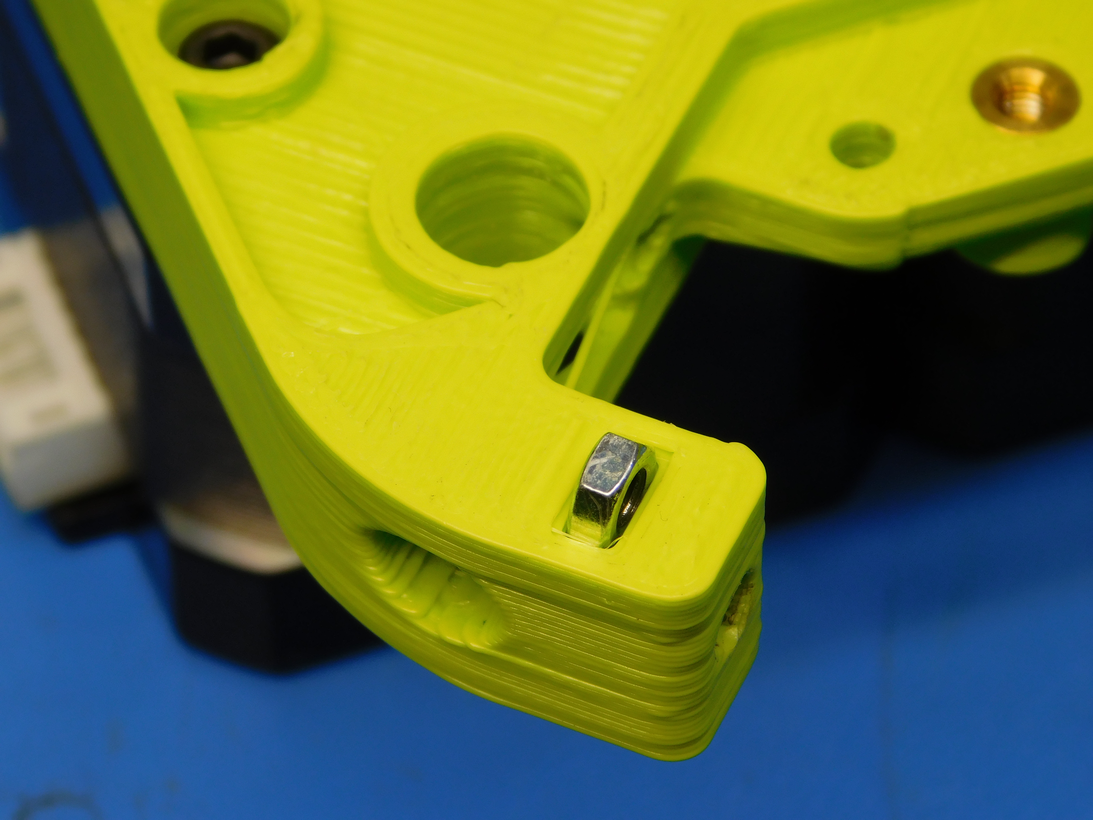
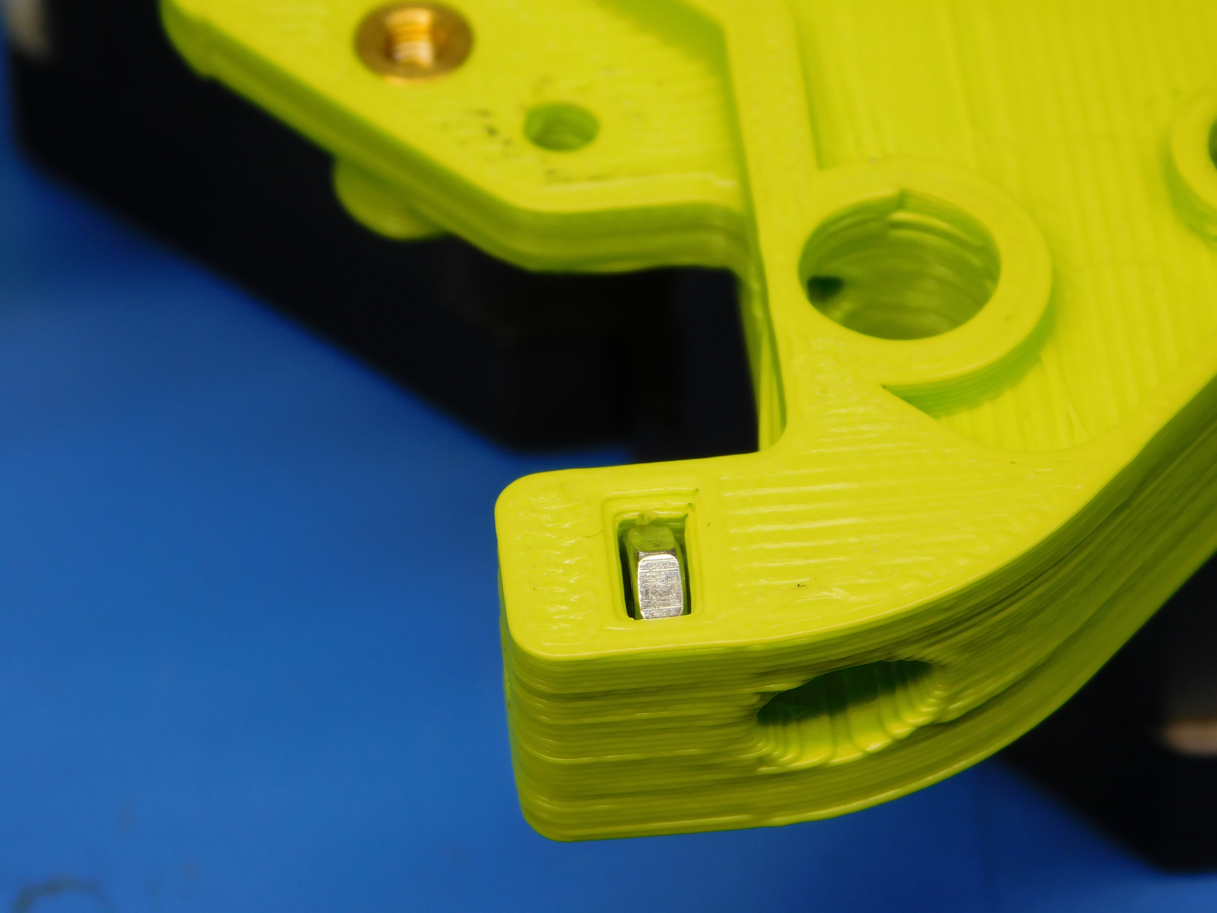
Put two M3 nuts [HD-NT0004] into the slots in the printed part. Then install the large gear and hobb assembly as shown. Make sure at this point that the gears can turn through their full revolution freely and that there is no binding or grinding.
Using one M3 x 16 SHCS [HD-BT0185] and one M3 washer [HD-WA0038], Install the front bearing housing to the extruder body assembly.
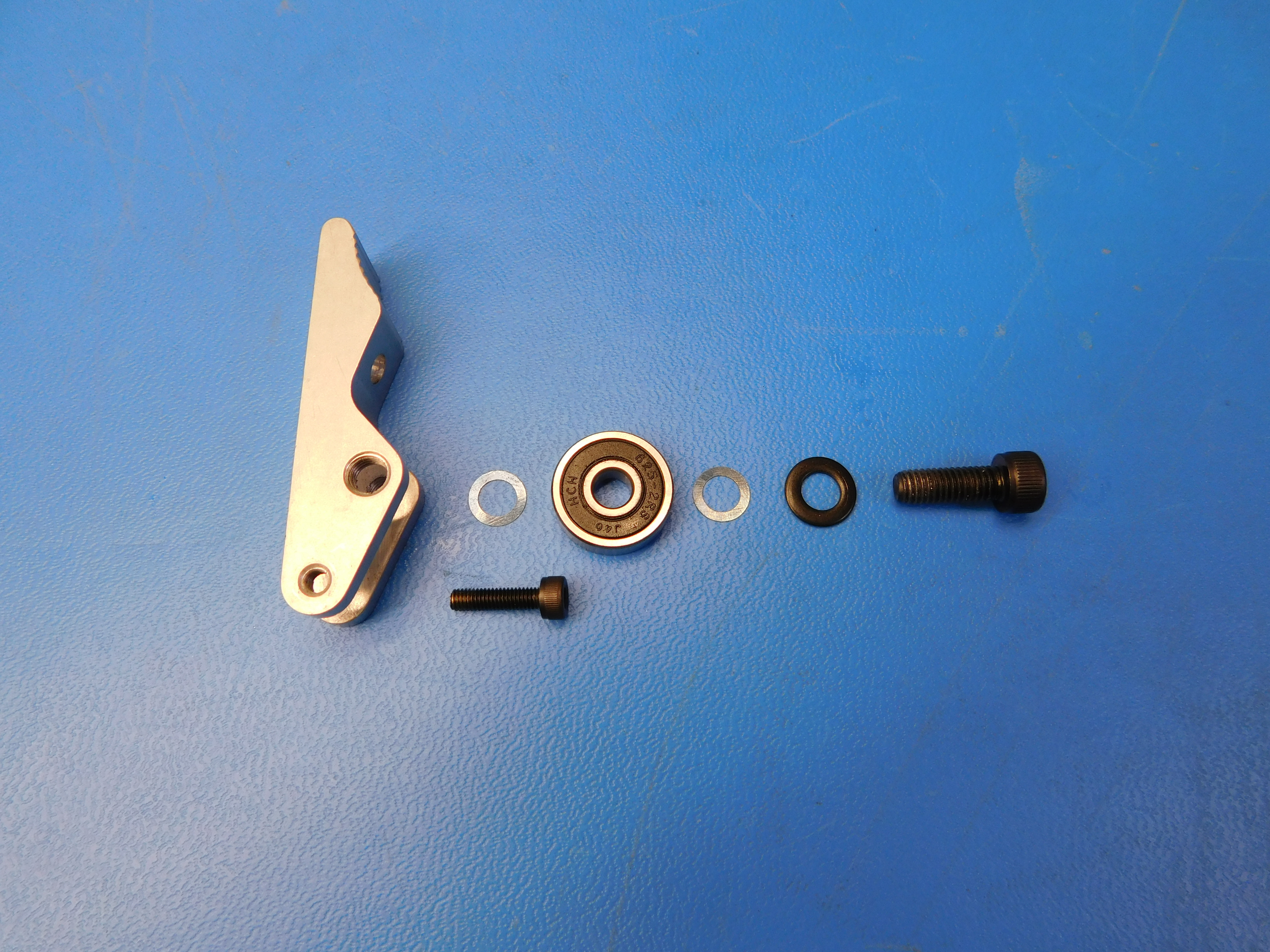
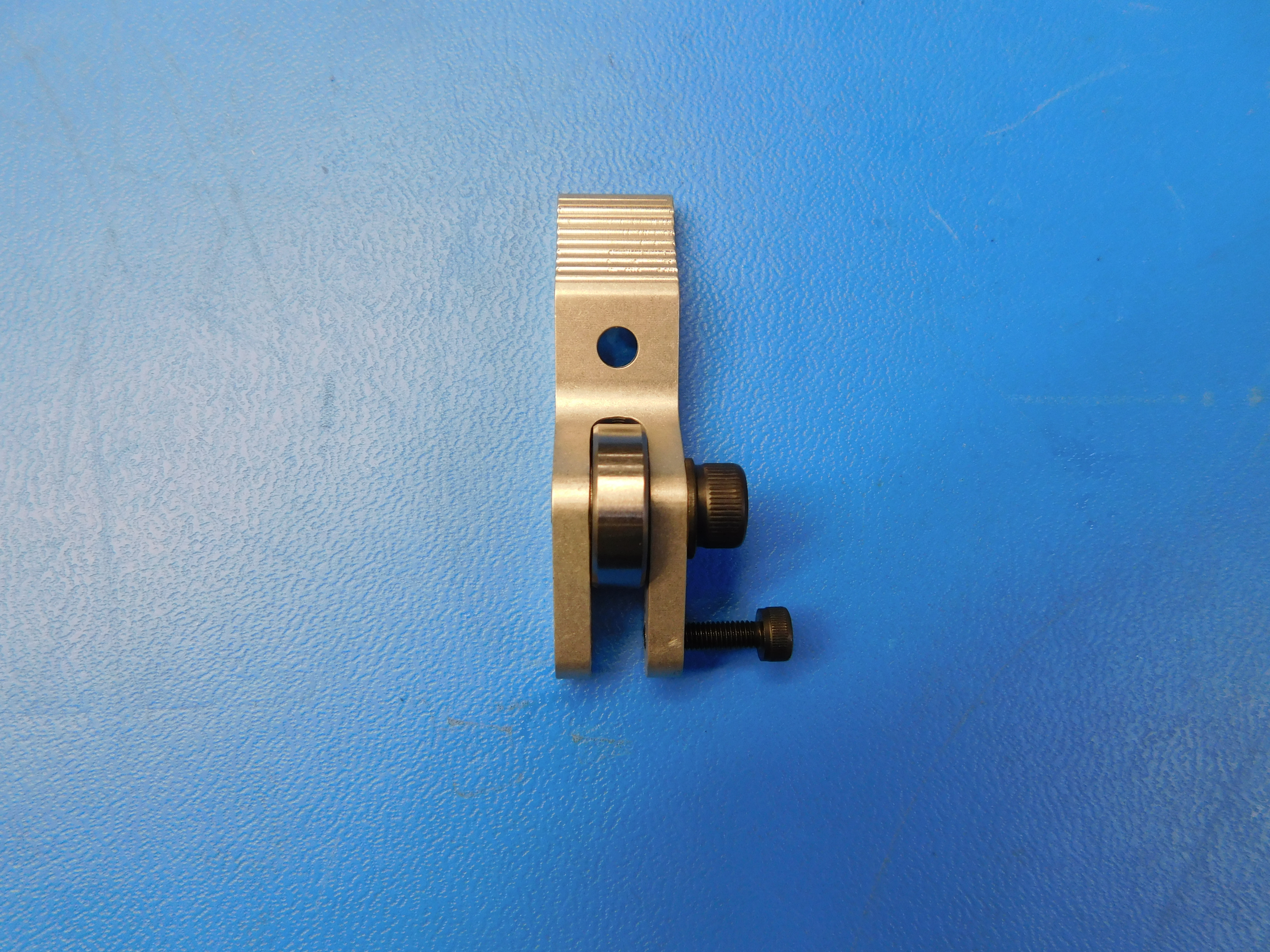
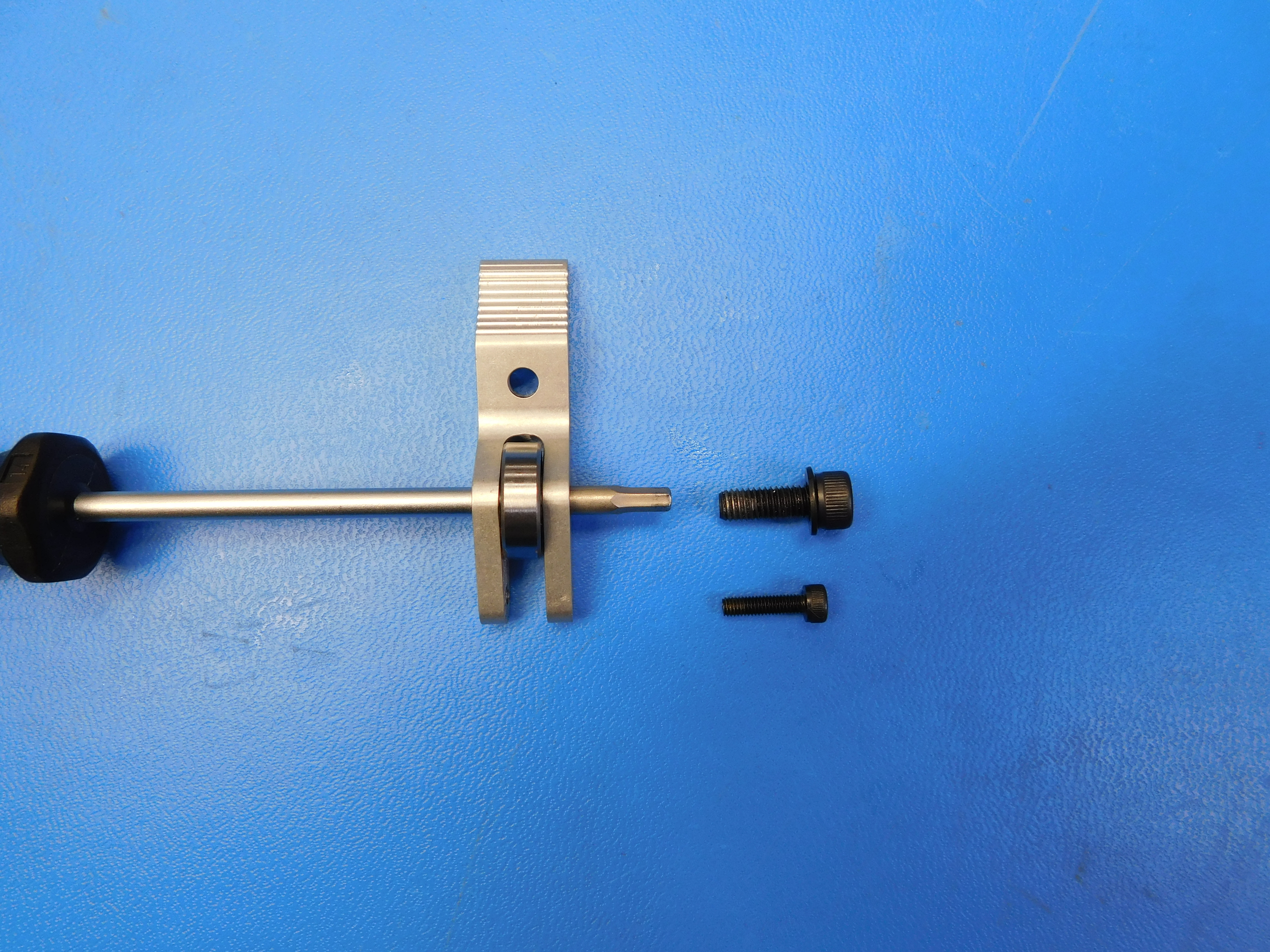
Assemble the idler blocks as shown. The shim washers [HD-WA0047] need to sit on either side of the bearing [HD-MS0411]. You can use a driver as an alignment tool to make installing the M5 x 14 SHCS [HD-BT0049] easier. You do not need to thread the M3 x 12 SHCS [HD-BT0039] all the way through the machined idler block [PP-MP0172] yet. Torque the M5 to 15 in * lbs. Make sure to use a M5 washer [HD-WA0040] as shown.
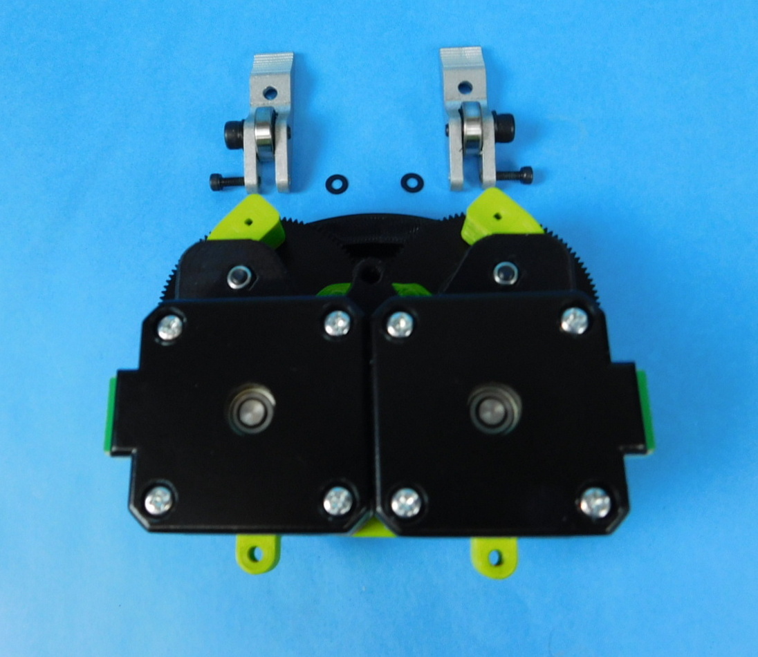
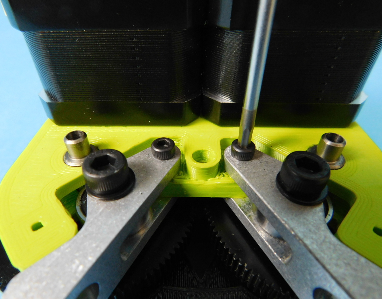
Install the idler blocks as shown.

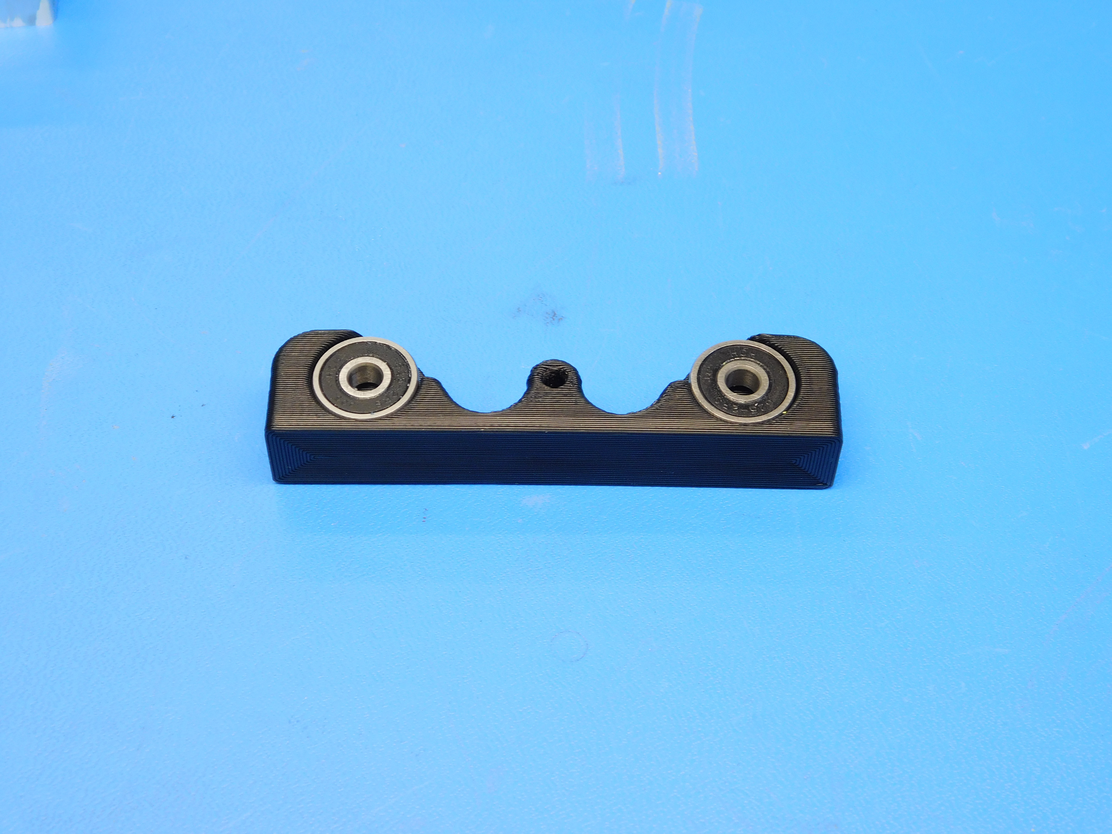
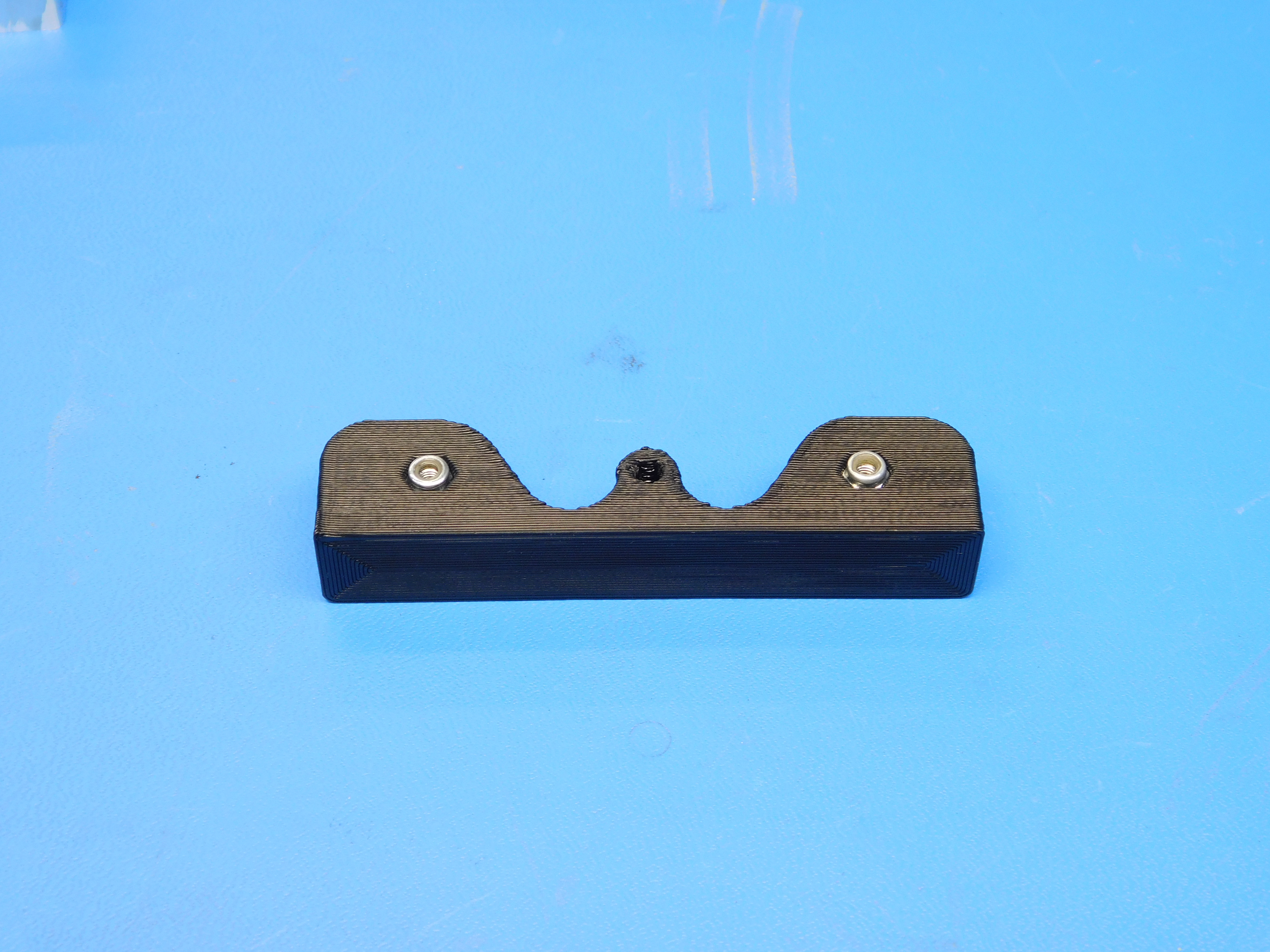
Press two bearings [HD-MS0411] into the rear bearing housing printed part [PP-GP0292]. Install the nyloc nuts [HD-NT0001] into the rear bearing housing. Push the nuts in until they stop.

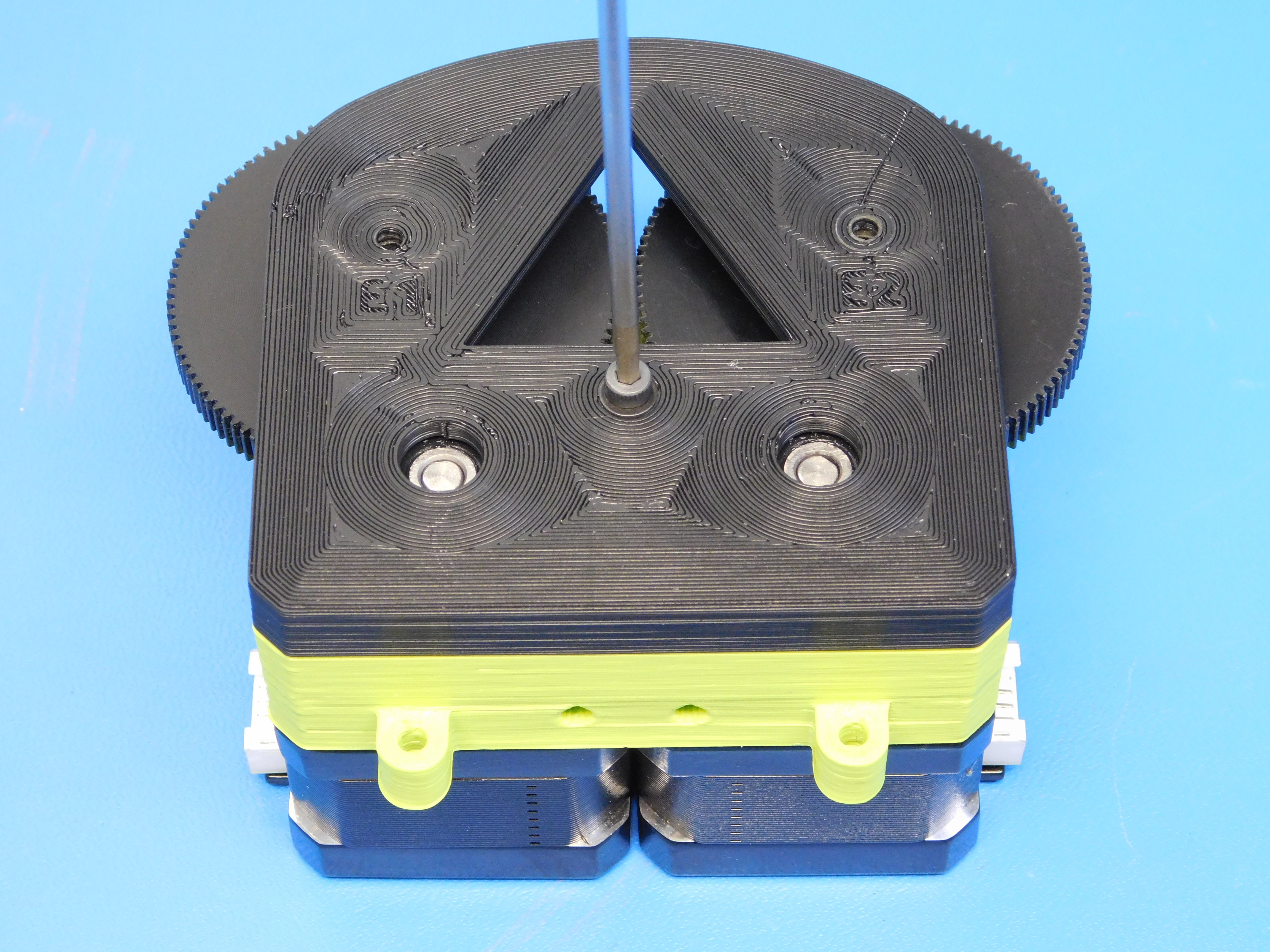
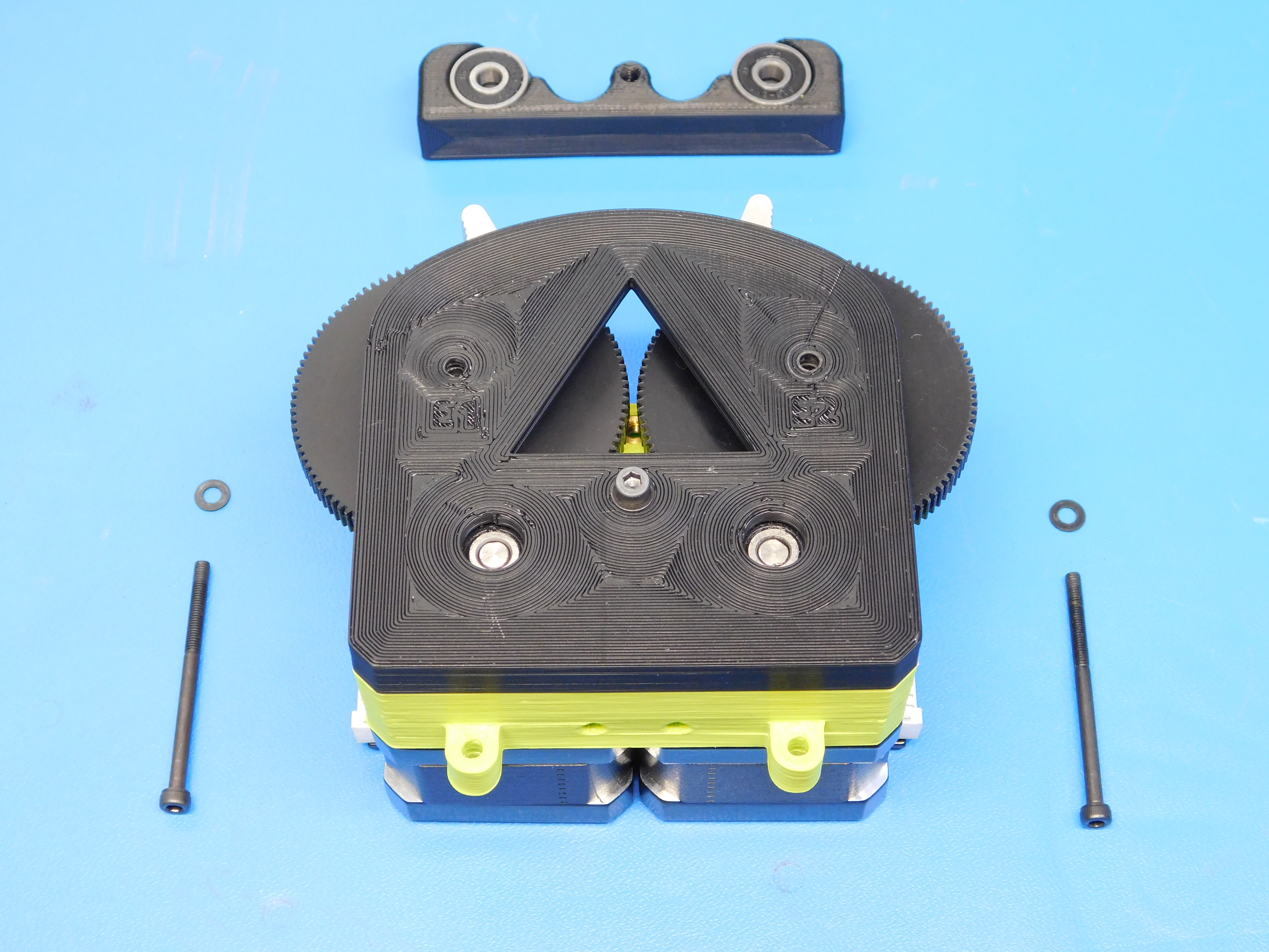
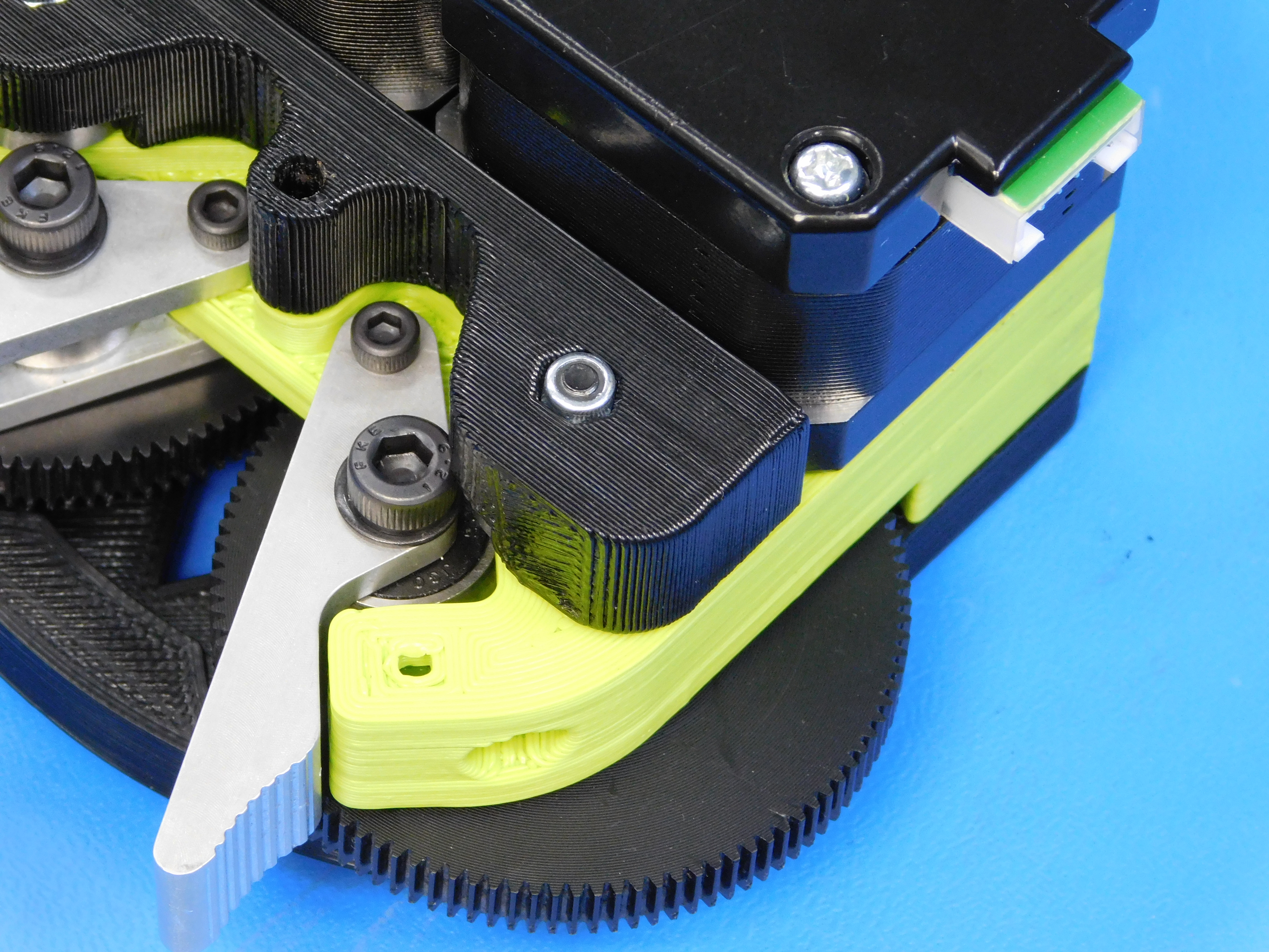
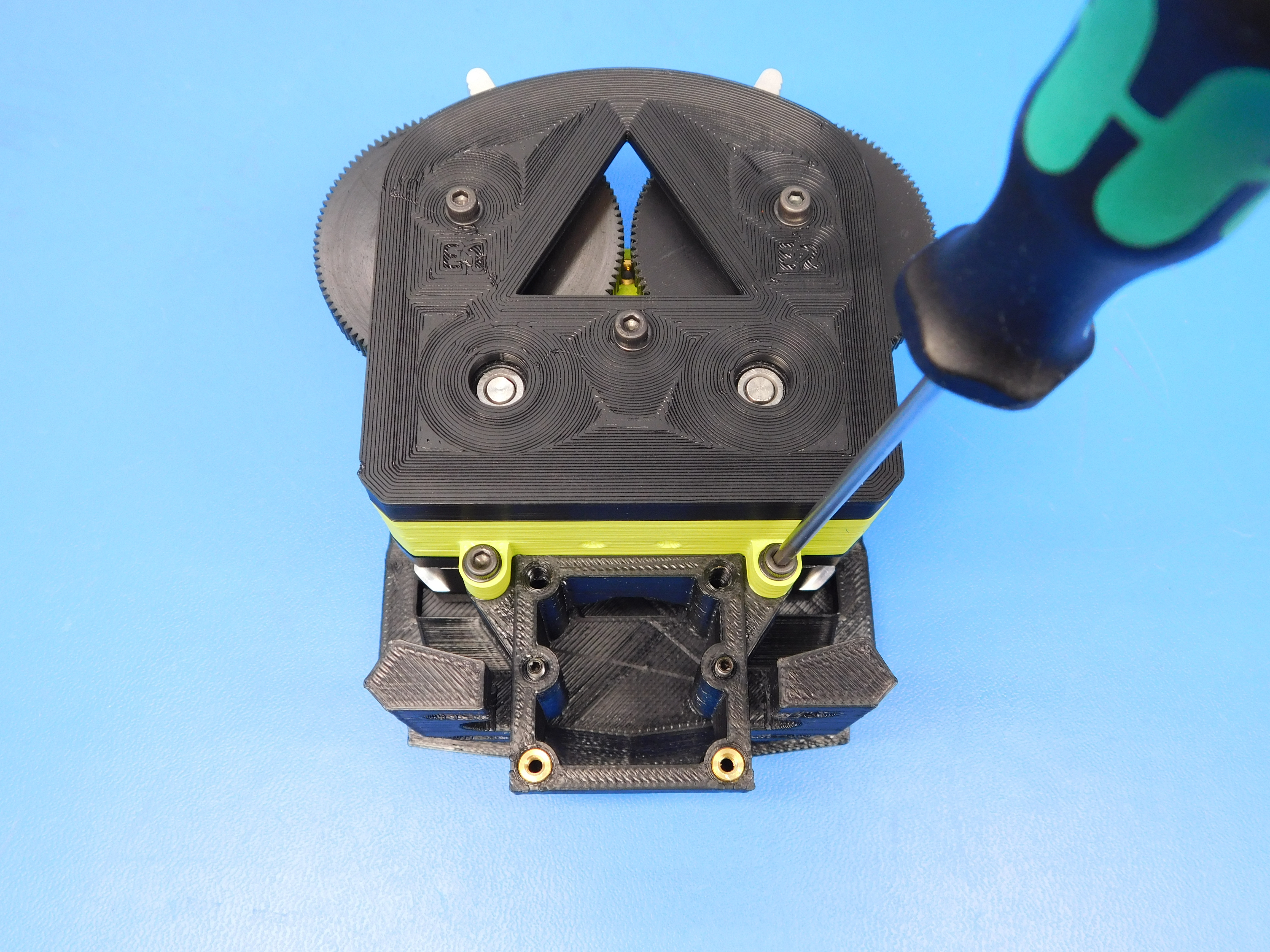
Install the rear bearing housing assembly [AS-TH0062] onto the back of the extruder body assembly. Using two M3x45 SHCS [HD-BT0154] and two M3 washers [HD-WA0038] fasten the rear bearing housing assembly to the extruder body assembly. Make the ends of the bolts flush with the nyloc nuts. Again, make sure at this point that the gears can turn through their full revolution freely and that there is no binding or grinding.
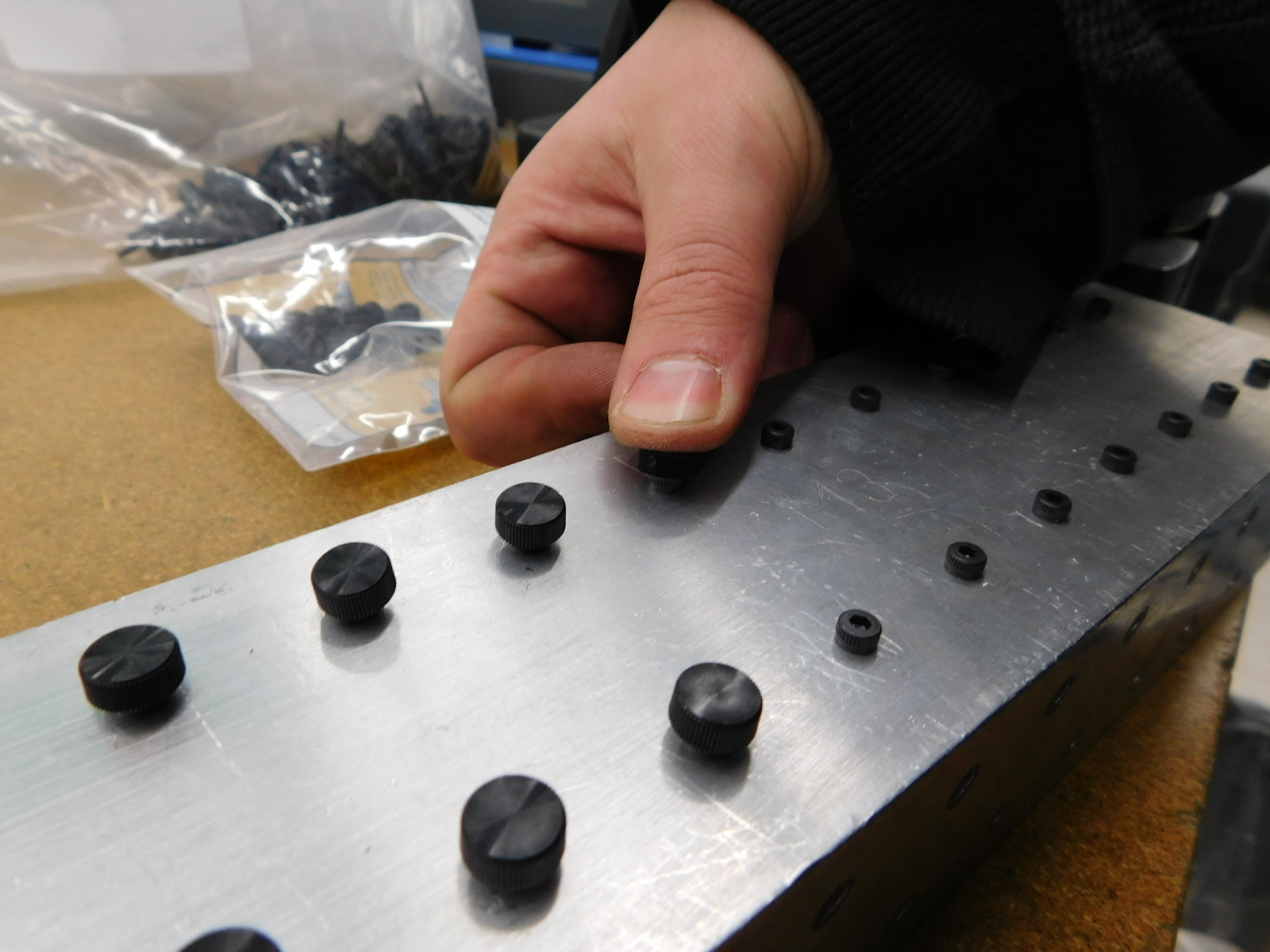
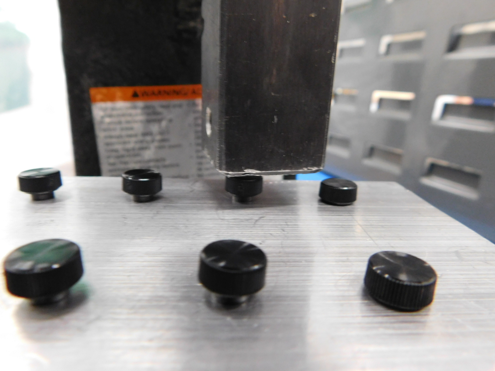
First, Place the thumbscrew caps [HD-MS0354] onto the idler bolts [HD-BT0042] by hand. Then, using the press, gently press the thumbscrew caps onto the idler bolts. This will create a new part number [AS-TH0067] called screw with thumbcap
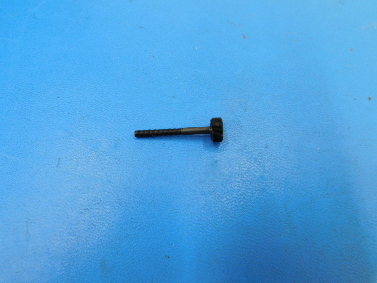
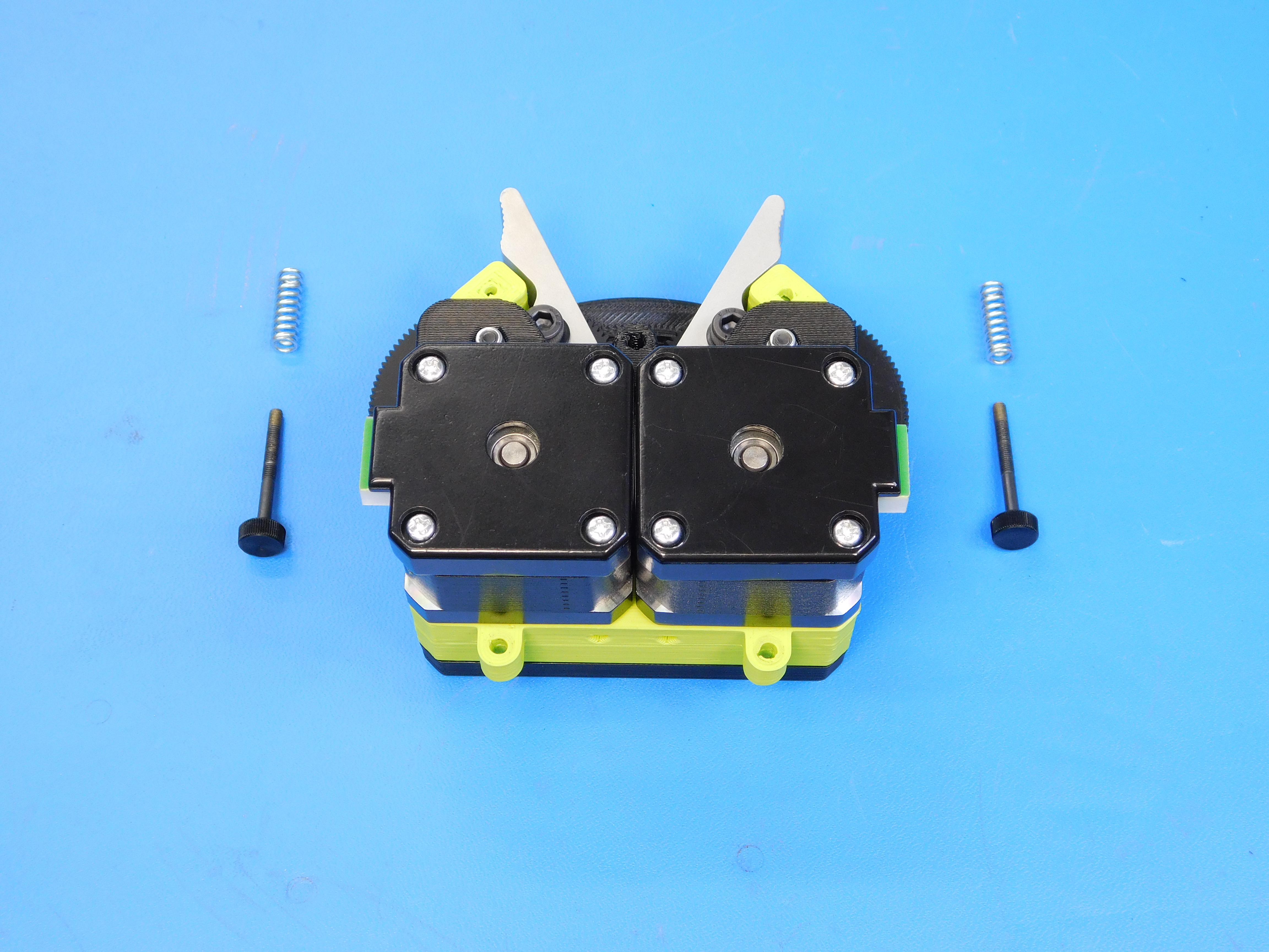
Install the idler screw and springs [HD-MS0421] through the idler assembly and extruder body into the M3 nut placed earlier. Thread the screws until they are flush with the filament holes as shown.
Assemble the wiring harnesses according to drawings. These drawings are available here: https://devel.lulzbot.com/TAZ/accessories/yellowfin/production_parts/electronics/cable_drawings/
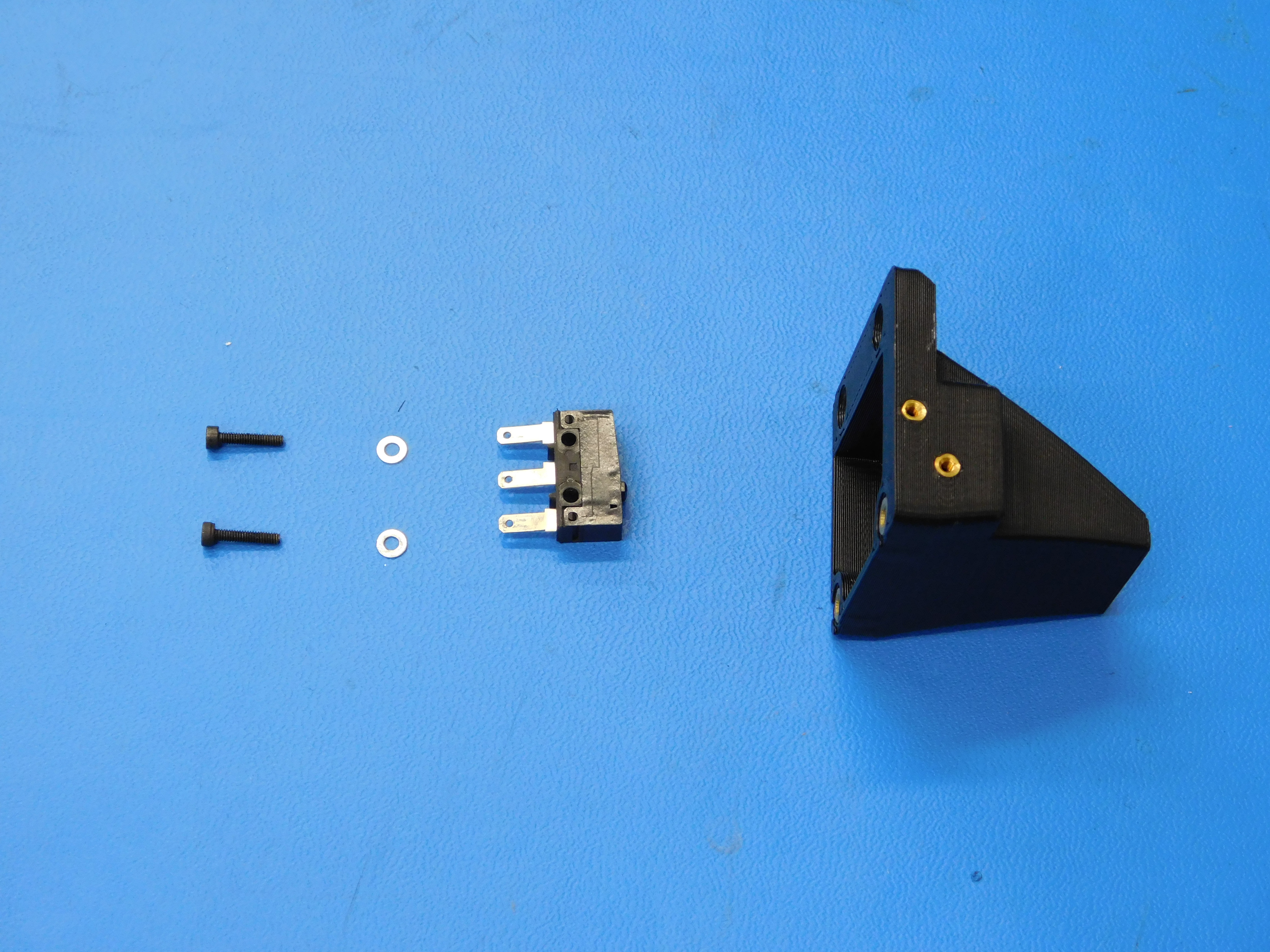
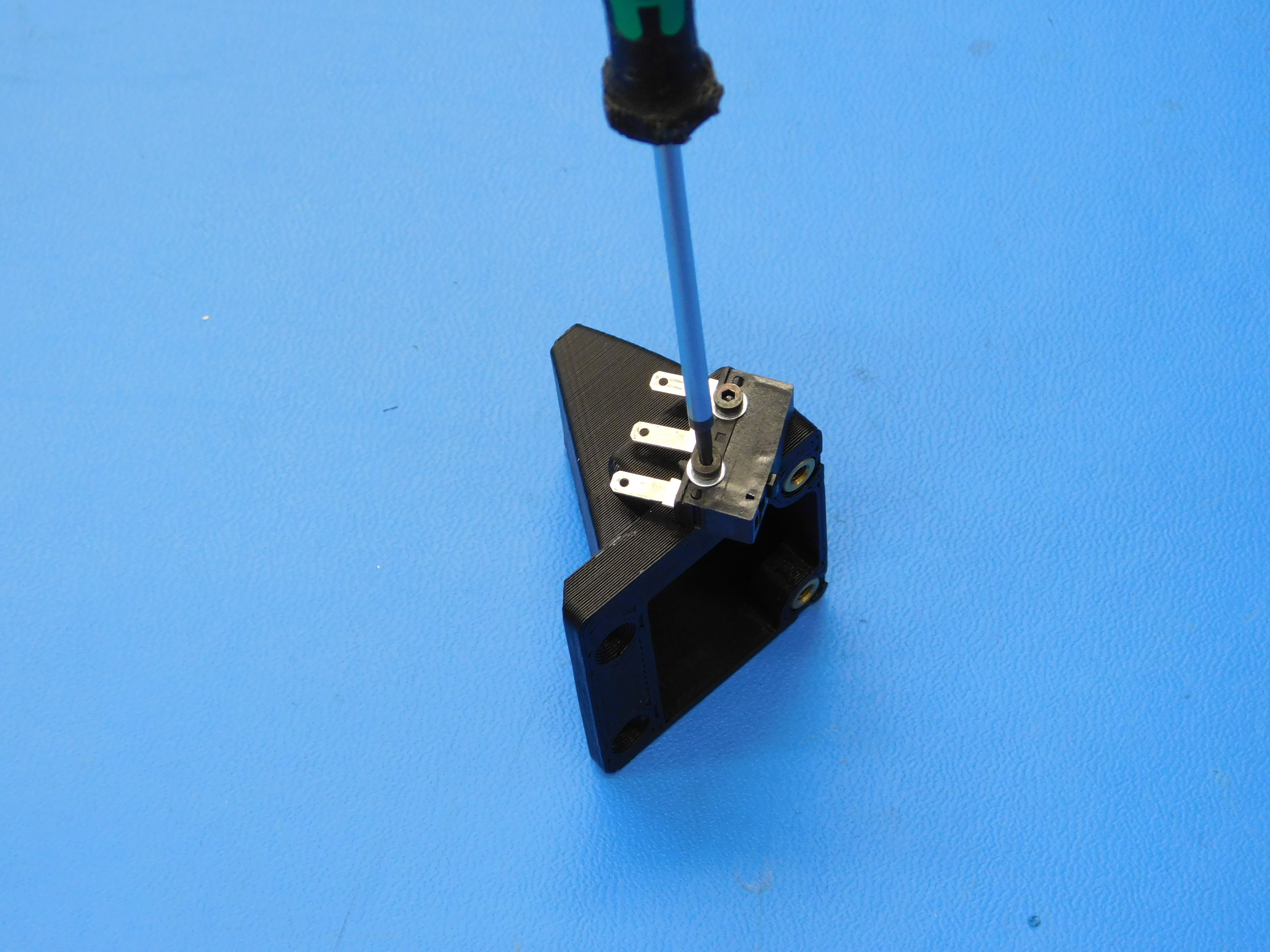
Using two M2 x 10 SHCS [HD-BT0107] and two M2 washers [HD-WA0012], Fasten the endstop [EL-SW0022] as shown.
Thread the alignment set screws [HD-BT0012] about half way into the holes in the extruder mount.
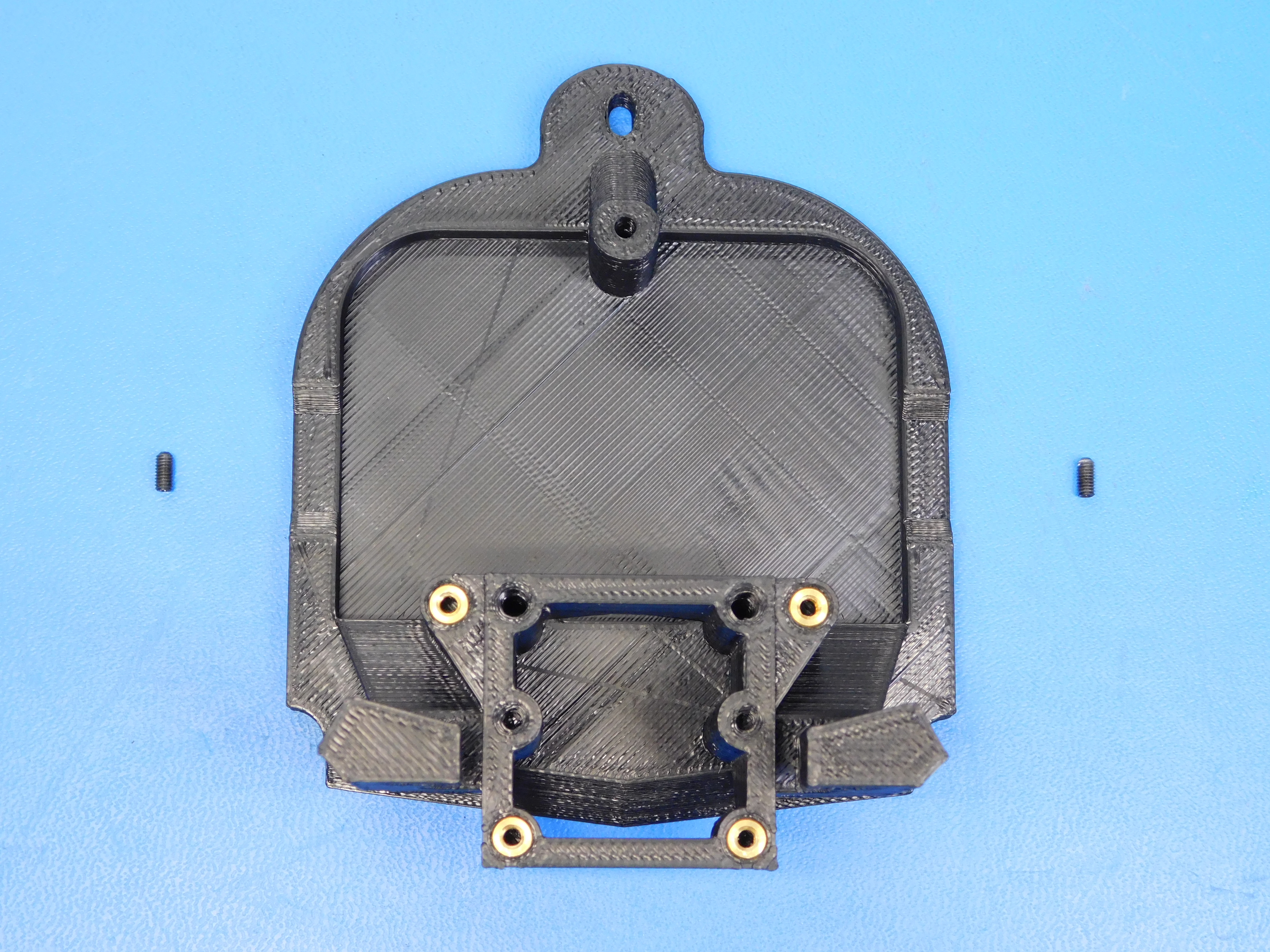
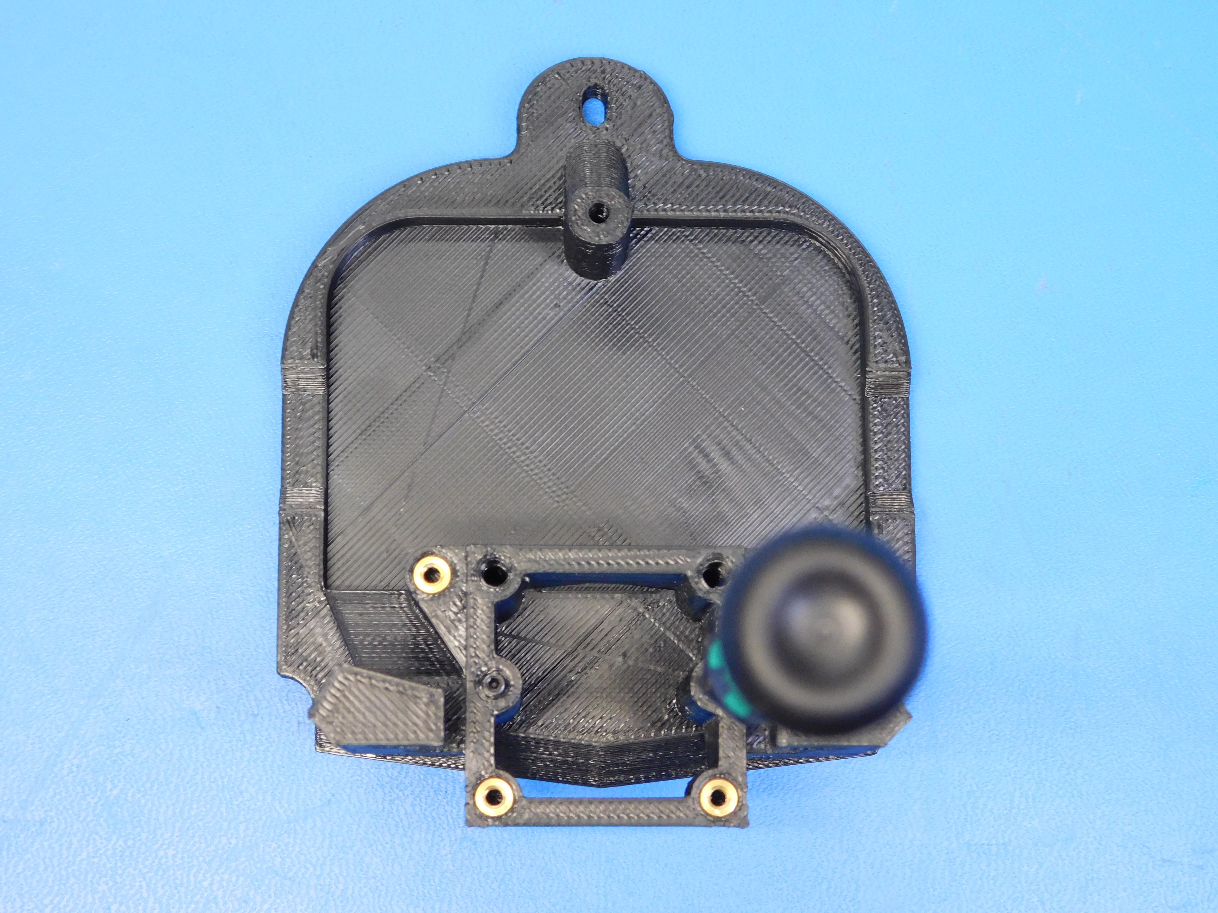
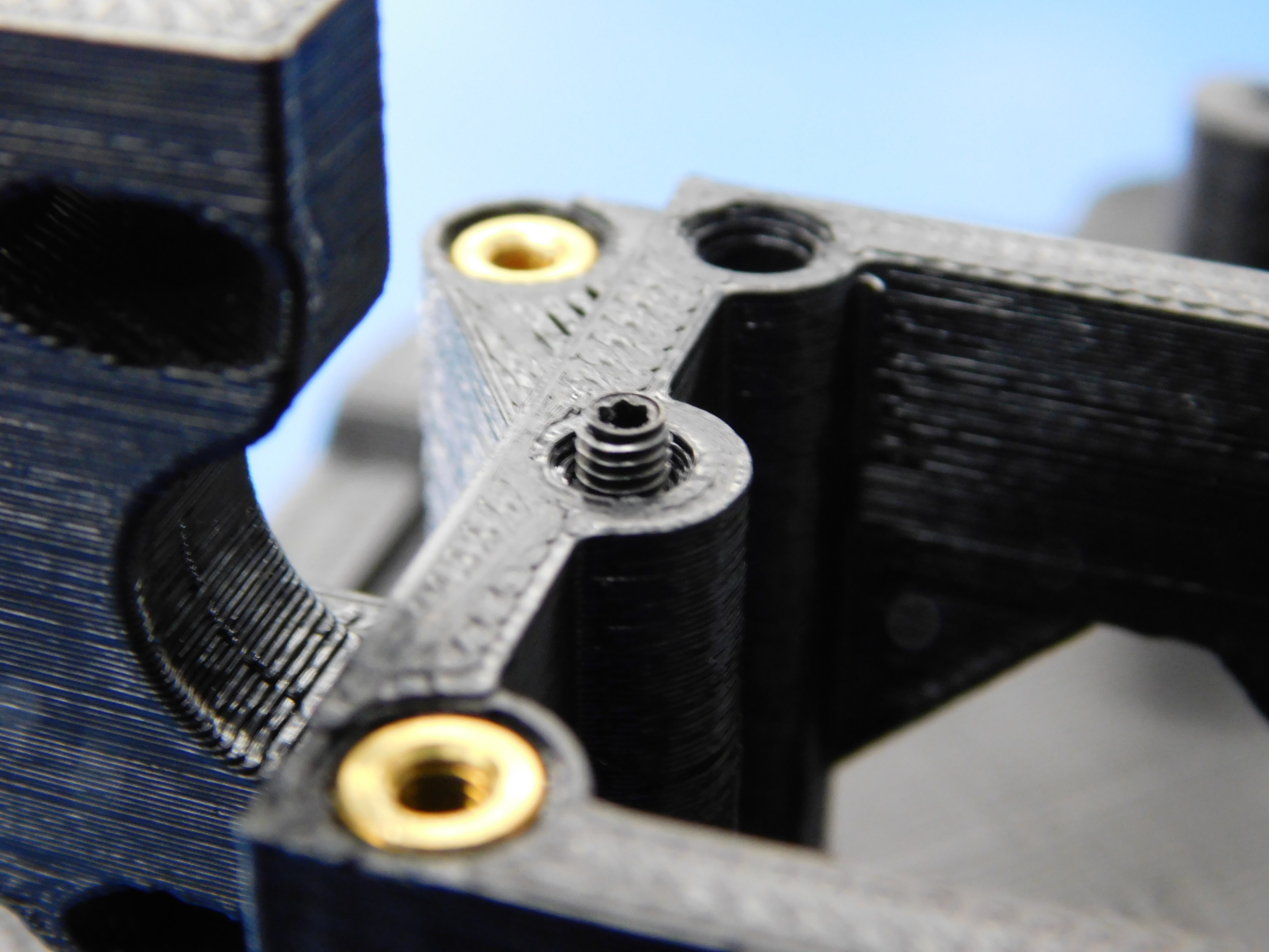
Using one M3x30 [HD-BT0042], two M3x12 [HD-BT0039] and three M3 washers [HD-WA0038], fasten the extruder mount assembly to the mount as shown.
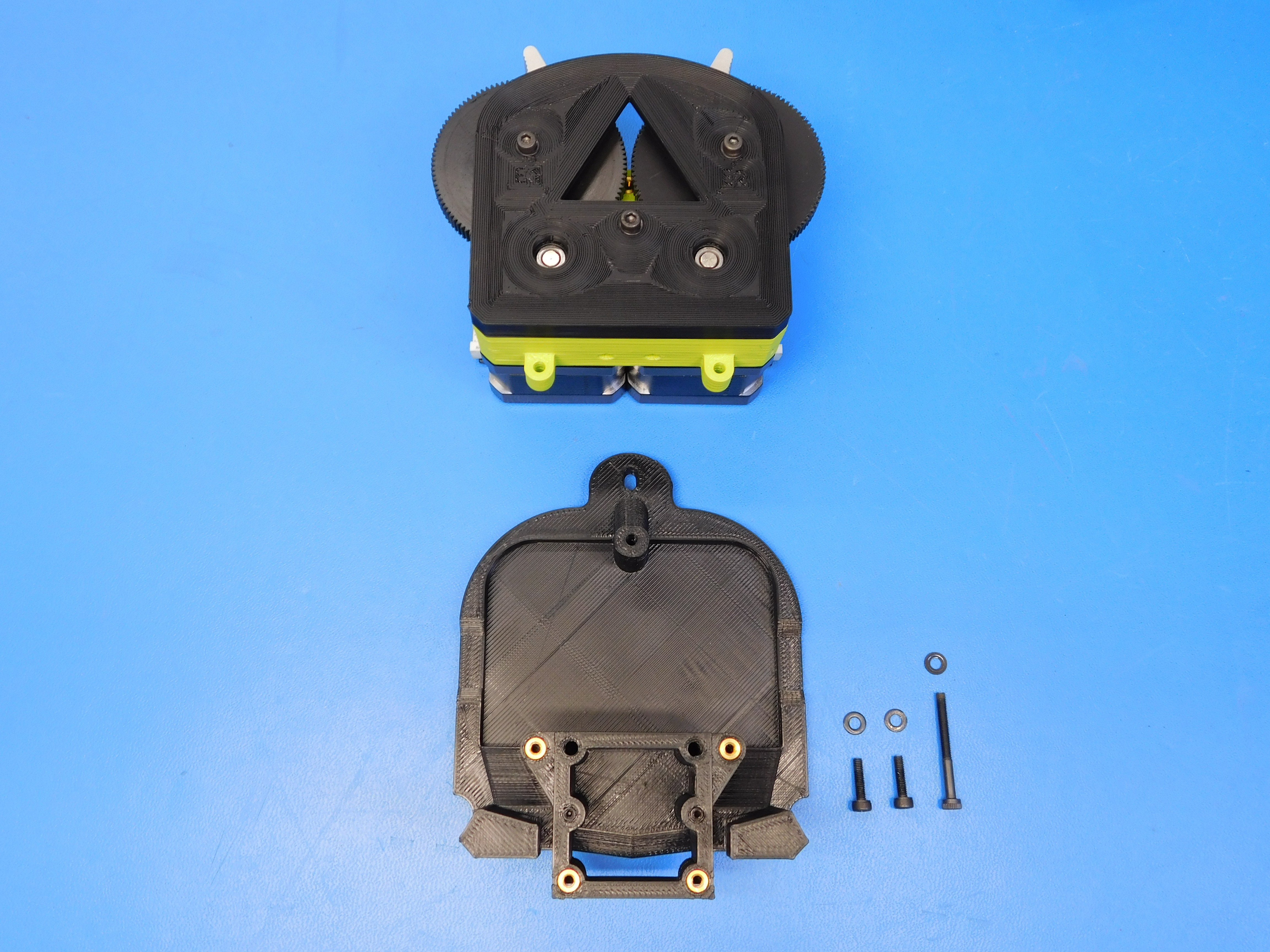
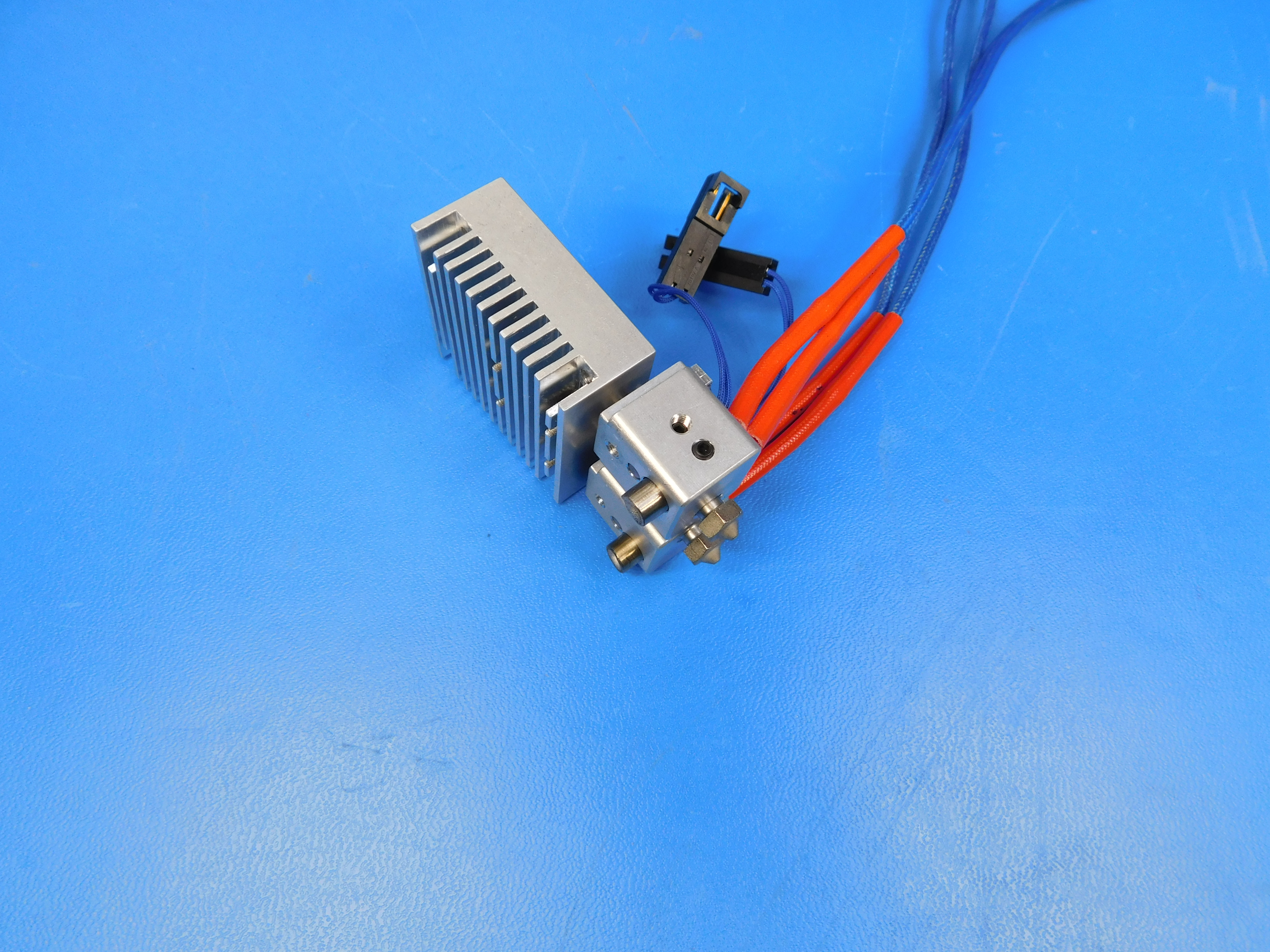
Place the heatsink assembly [AS-HE0018] onto the extruder mount so that the alignment set screws are lined up with the holes on the back of the heatsink.
Insert two pieces of filament to align the heatsink.
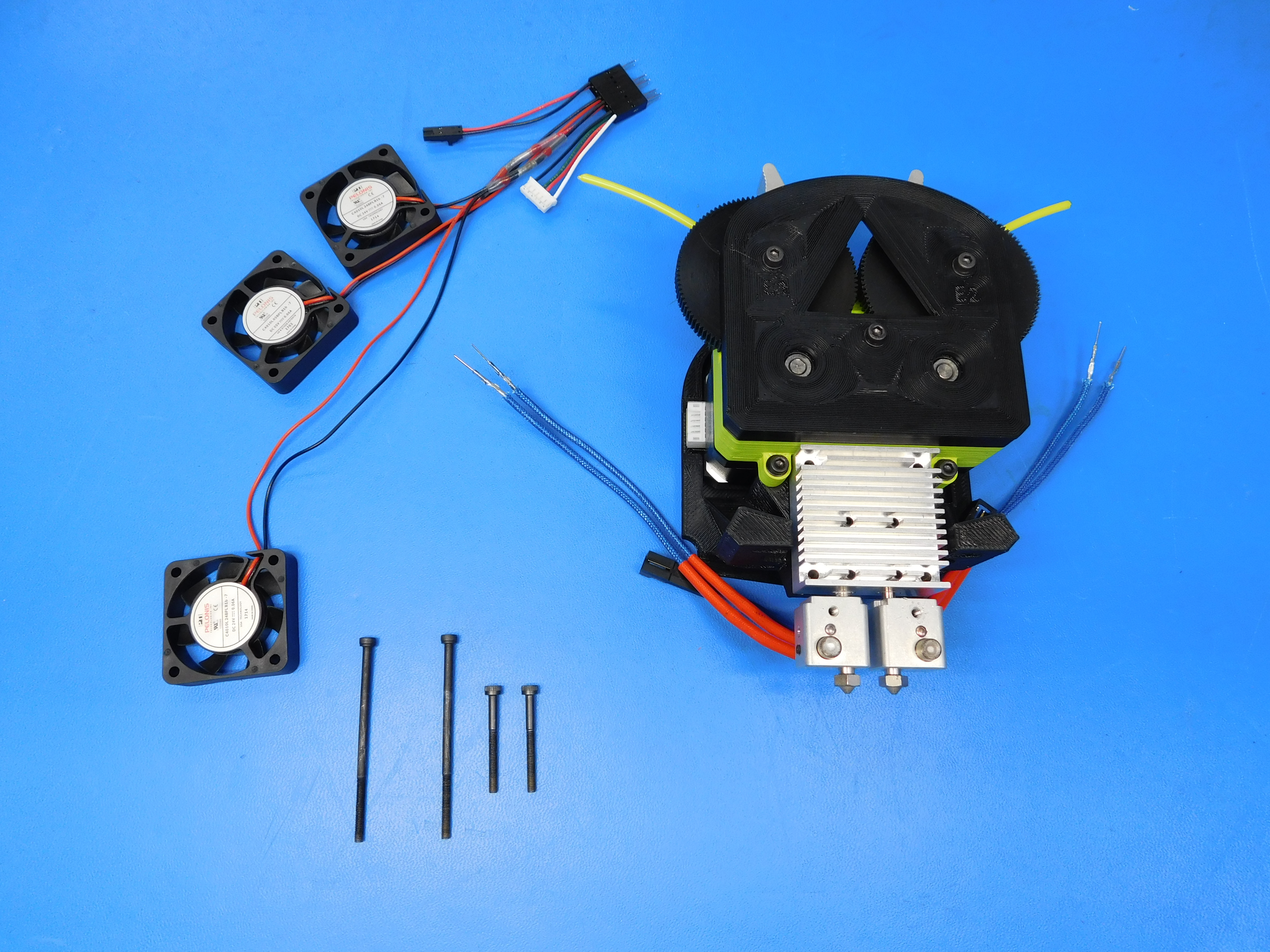
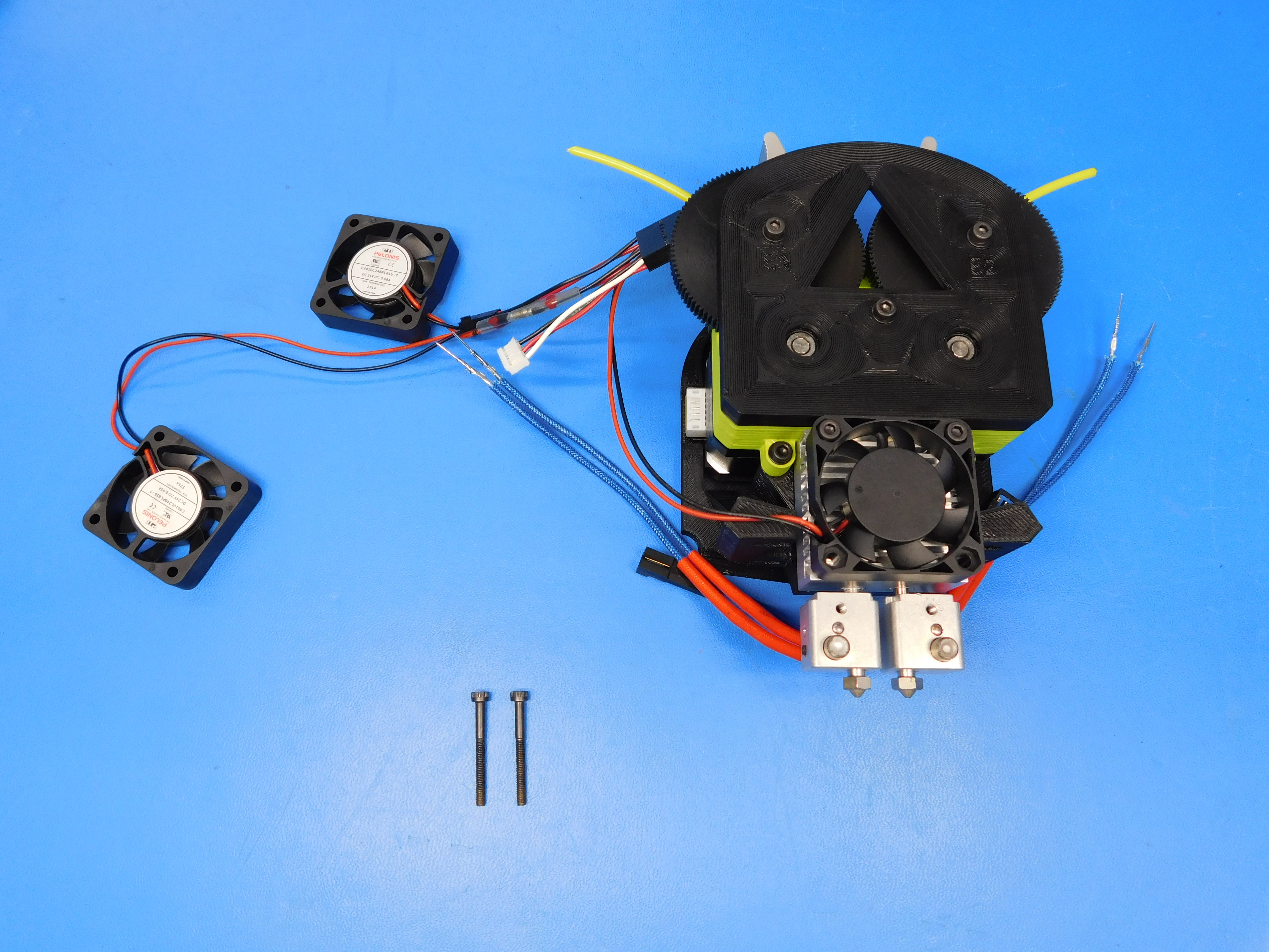
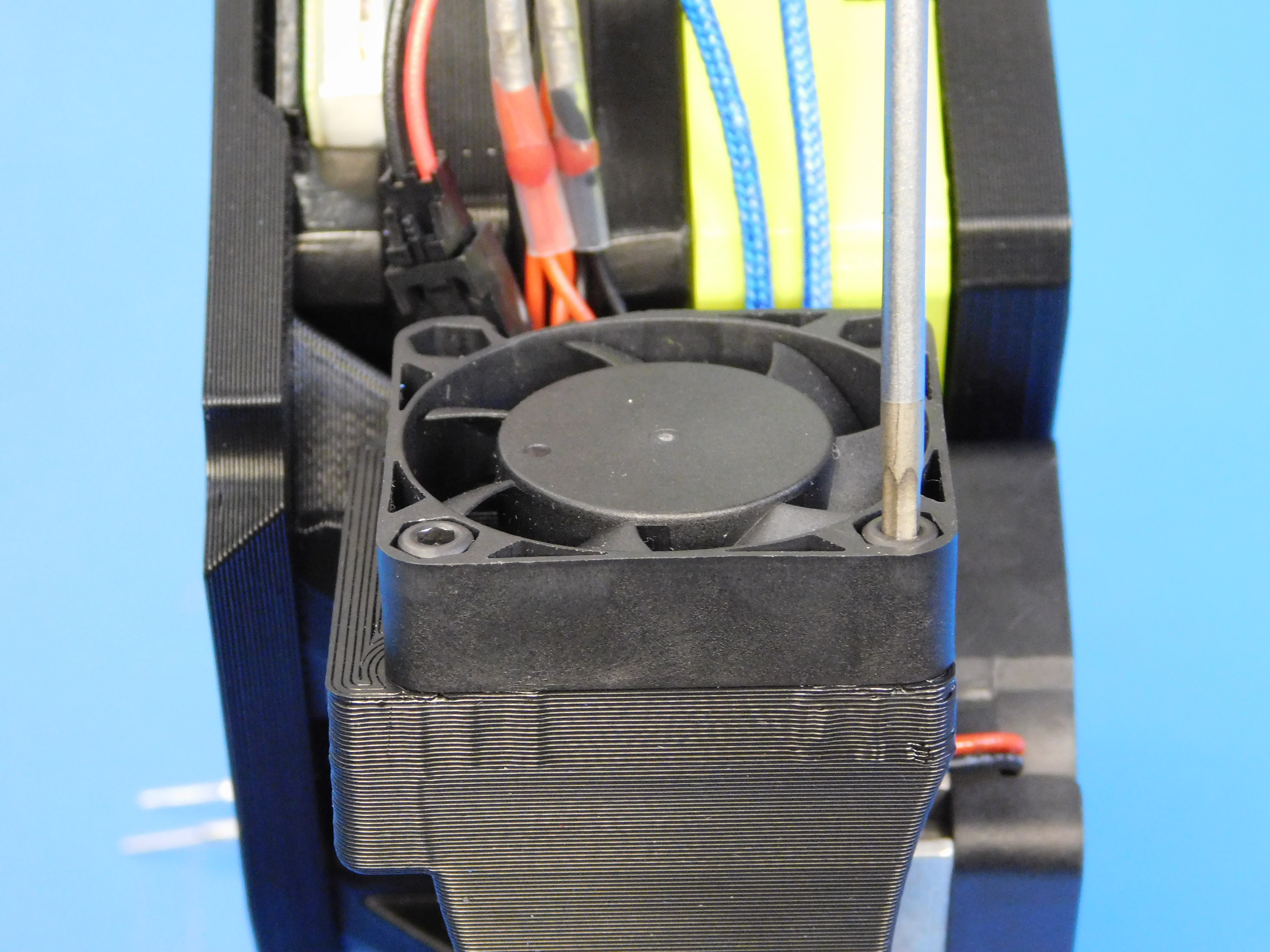
Place the heatsink fan on the right side harness [AS-CB0039] on top of the heatsink and then fasten the fan to the extruder mount assembly through the heatsink assembly using two M3x60 SHCS [HD-BT0203] on the top and two M3x30 SHCS [HD-BT0042] on the bottom.
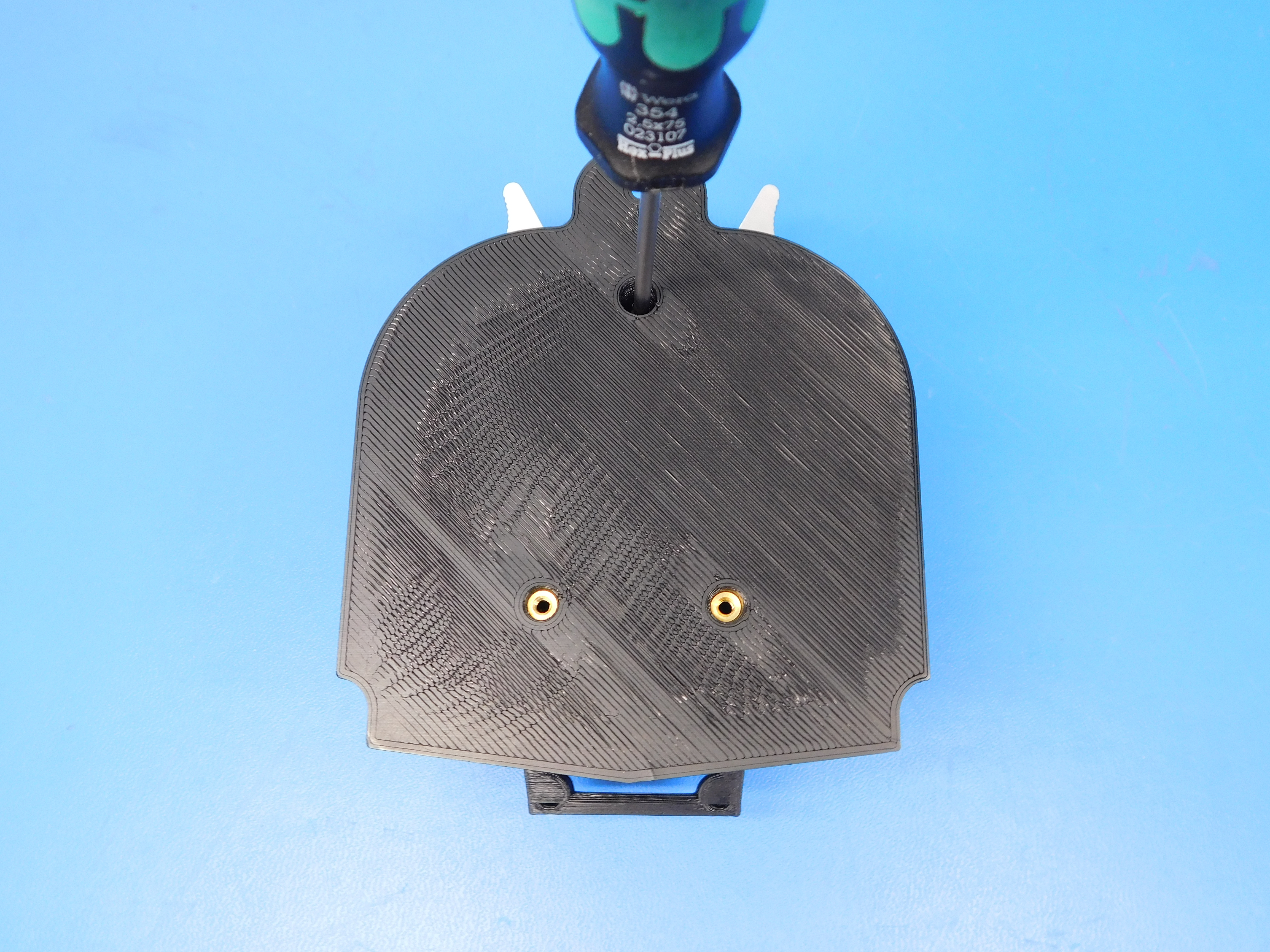
Make sure you can see the bolts in the inserts on the back.
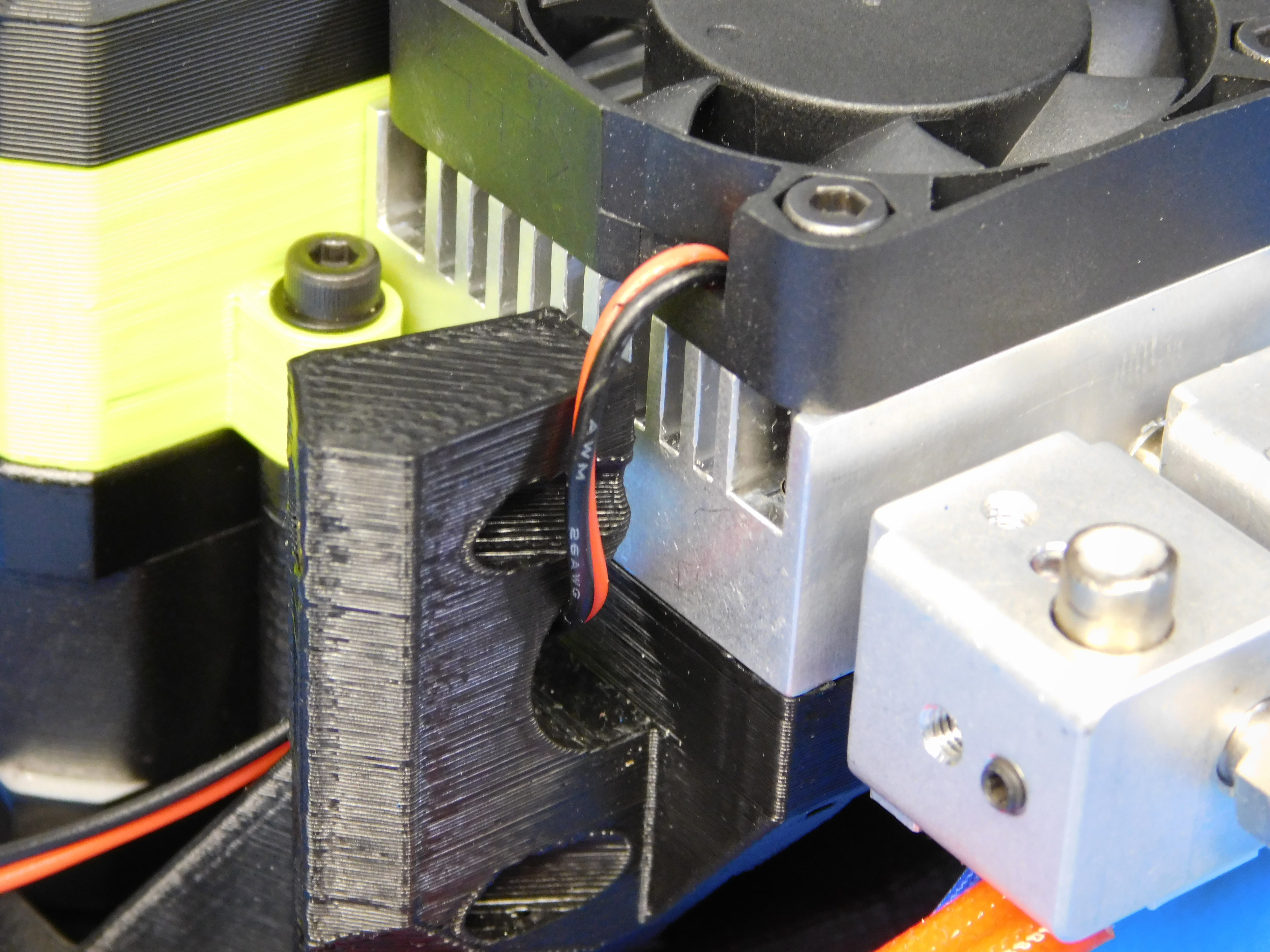
Route the heatsink fan wires as shown.
Route the thermistor wires as shown.
Make sure no wires get pinched in between the heatsink and the printed part.


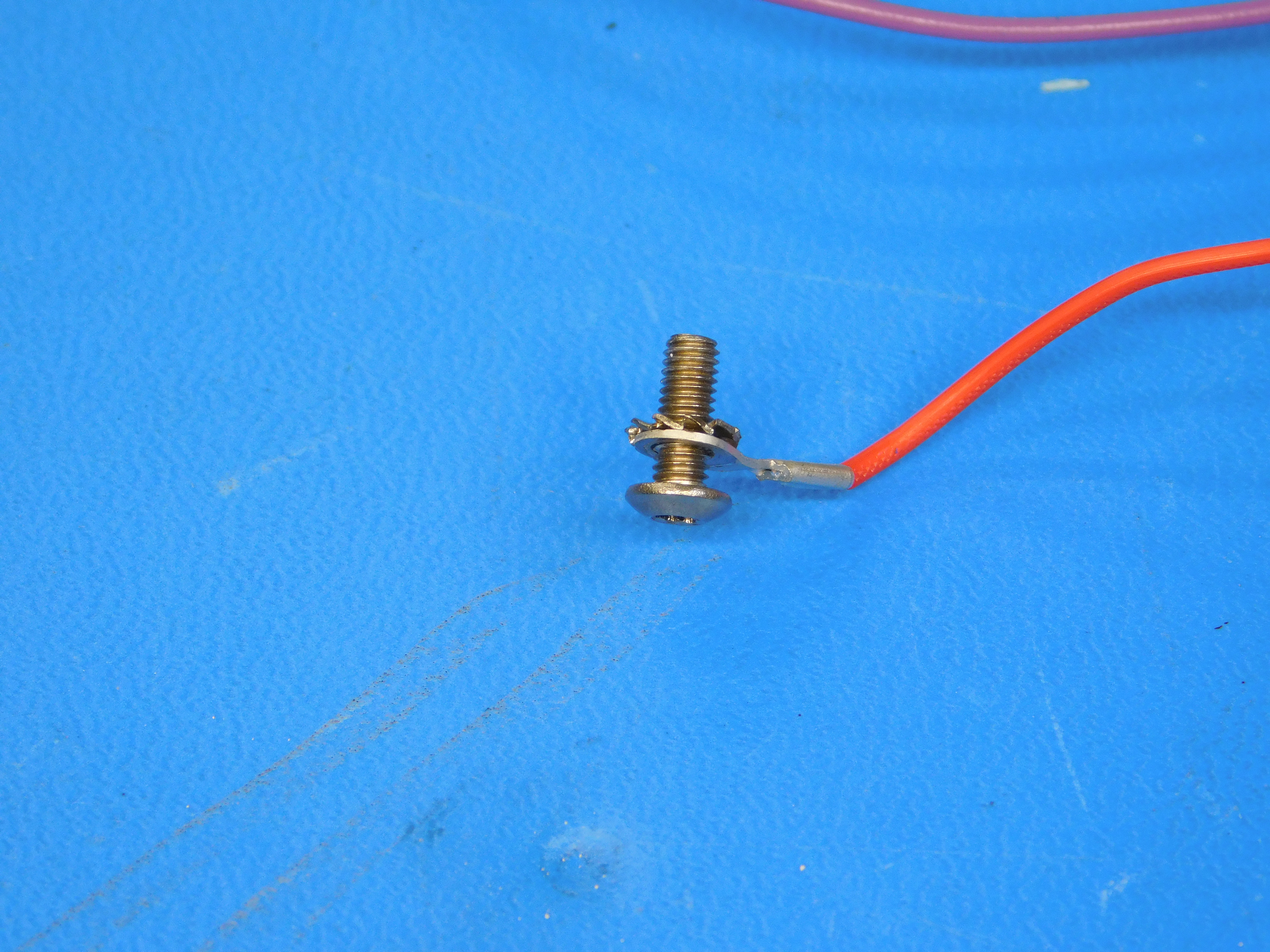
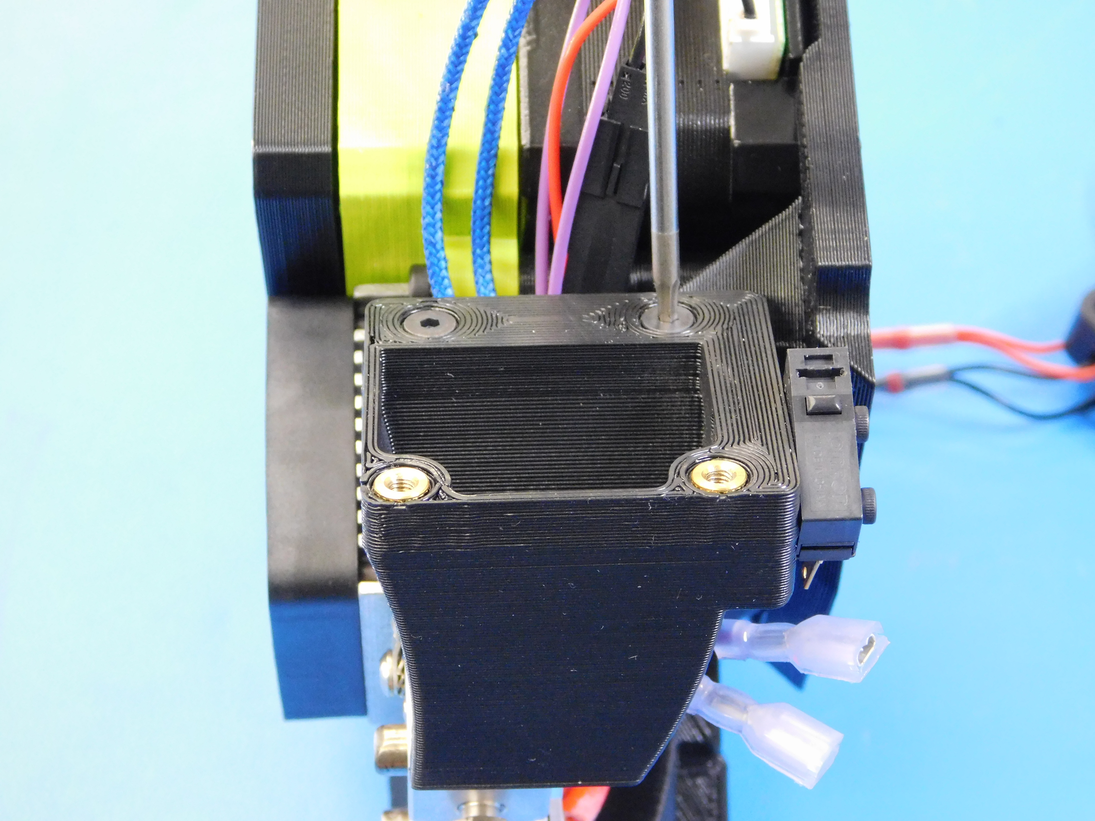
Using one M3 x 8 stainless BHCS [HD-BT0104] and one star washer [HD-WA0035] attach the zero sense line from the right side harness [AS-CB0042] to the heaterblock as shown. Route the endstop wires as shown. Note: the end stop wires go under the heater cartridge wires.
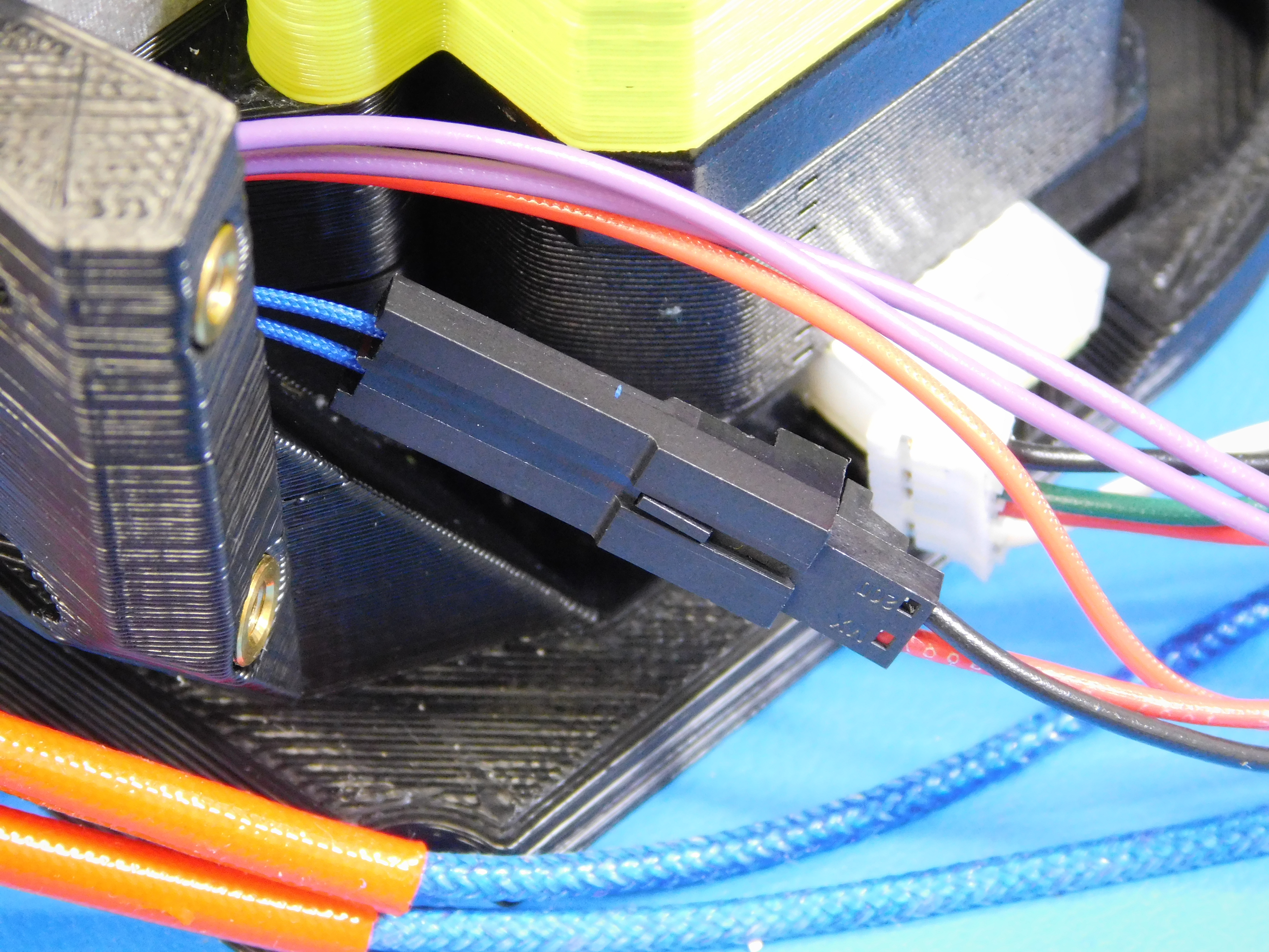
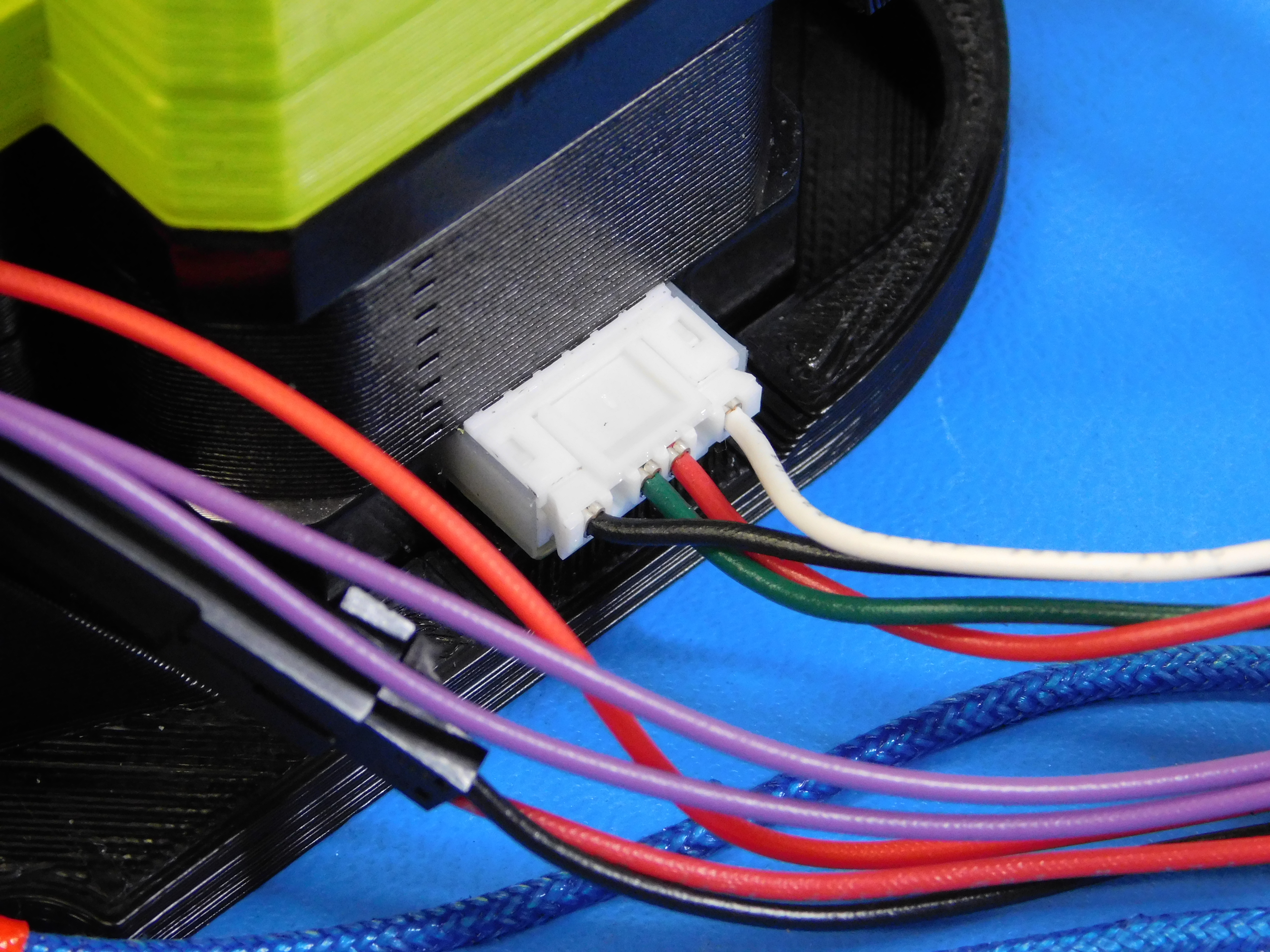
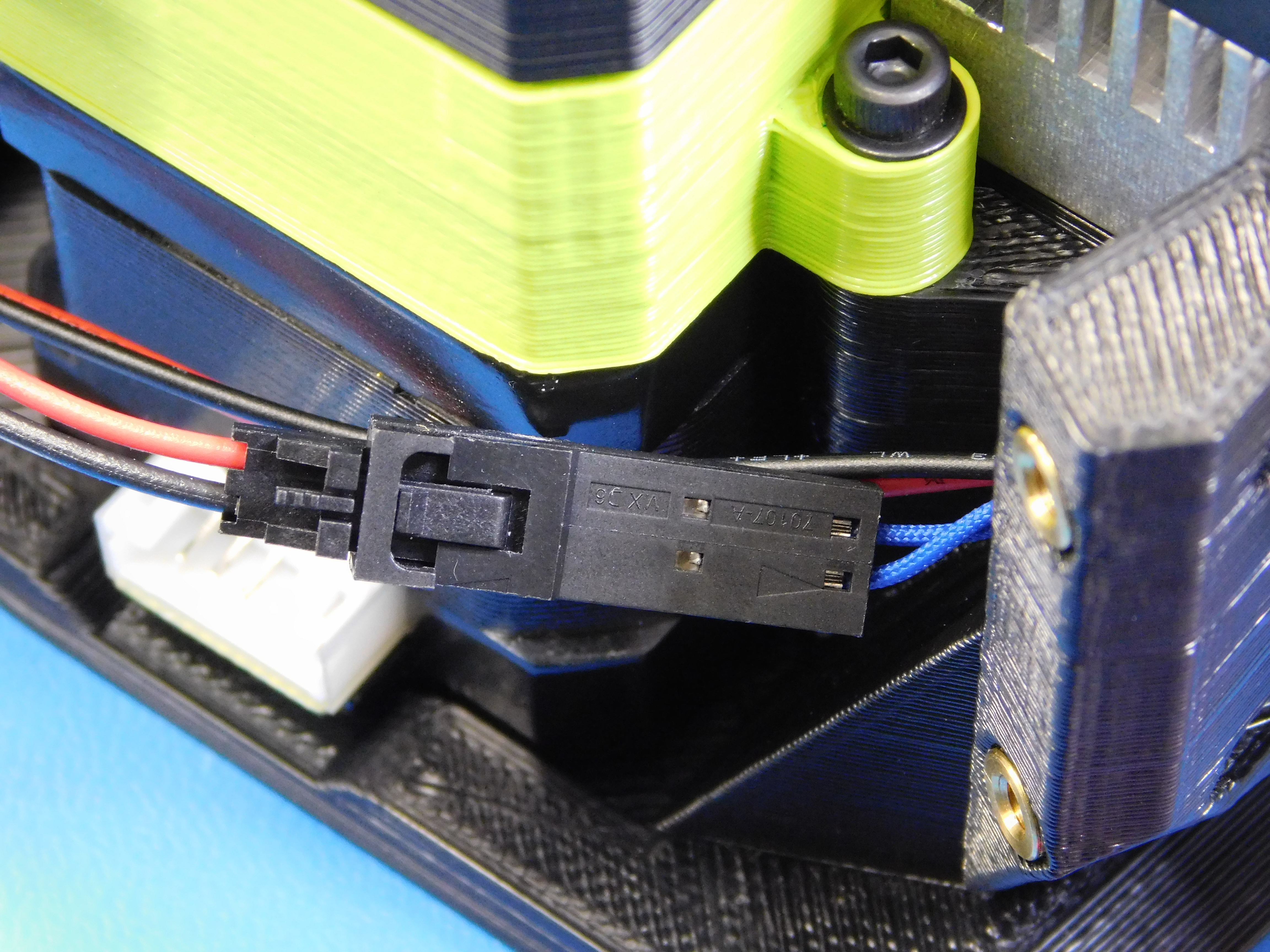
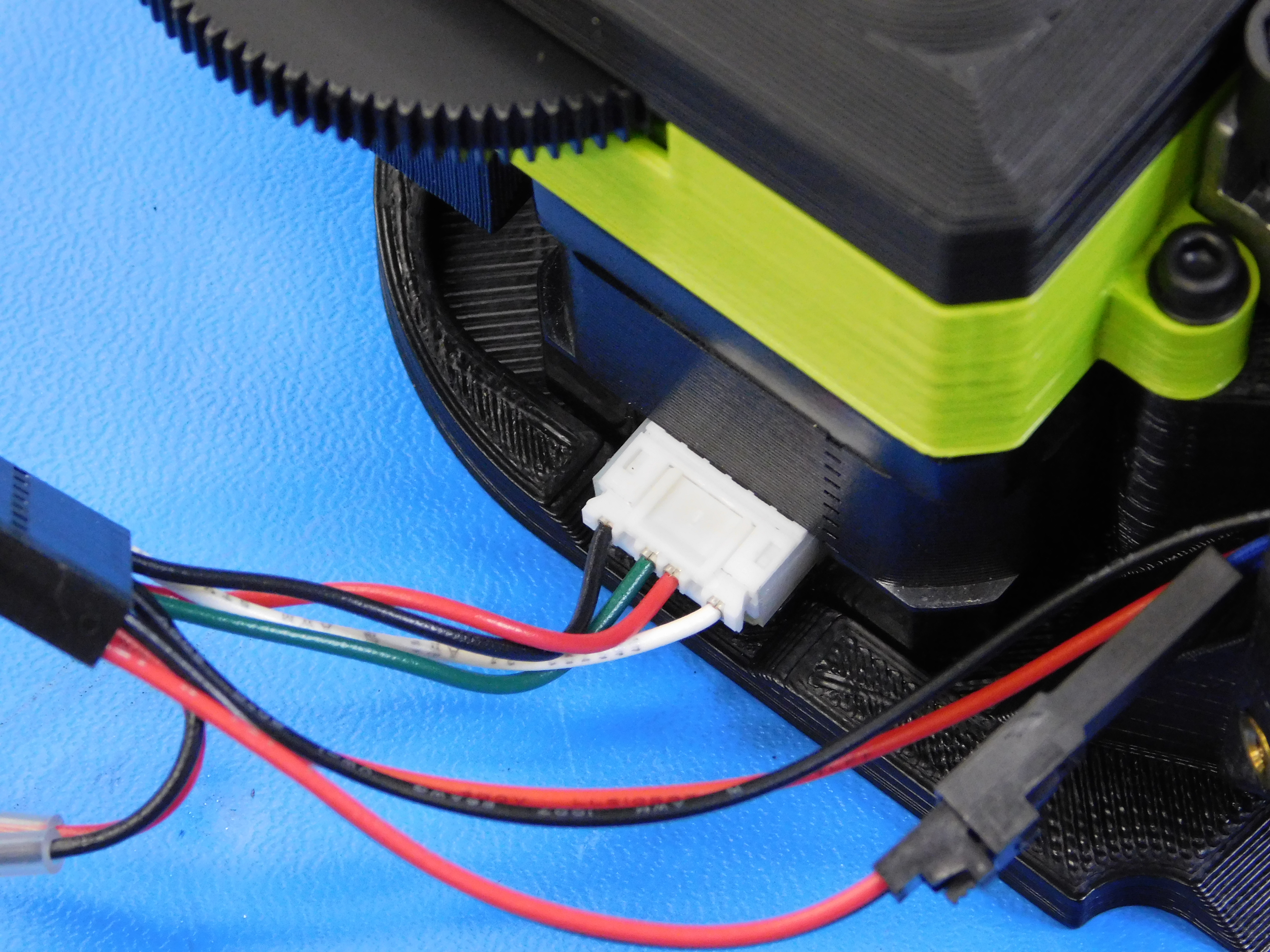
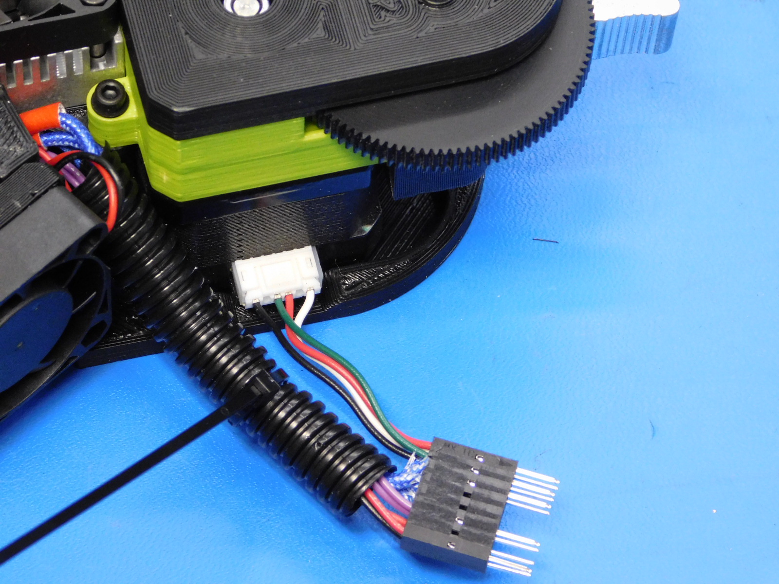
Connect the JST stepper motor connectors to the stepper motors as shown. Connect the molex 2 pin connectors as shown.
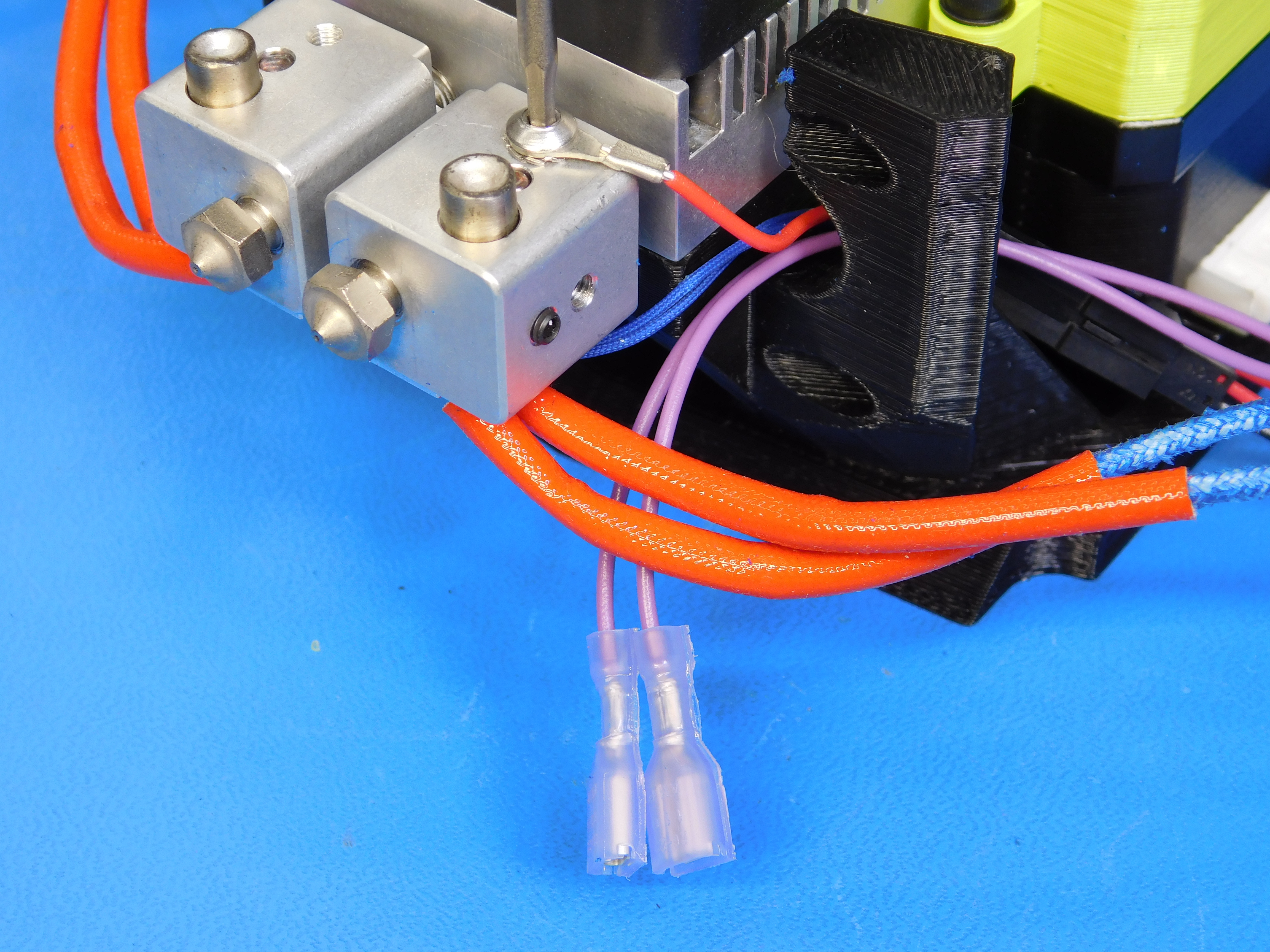
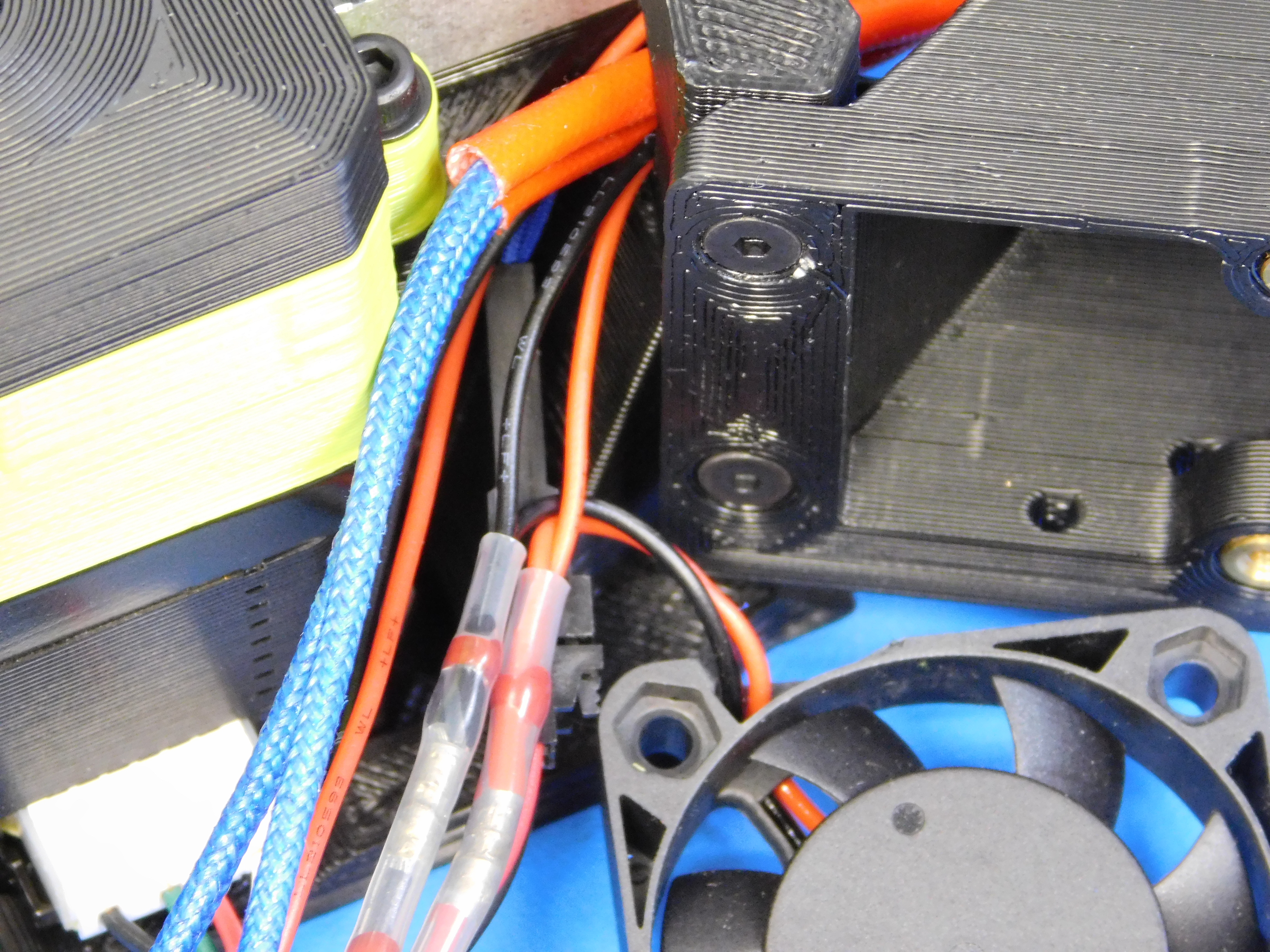
Route the heater wires as shown. Route the blue insulation first, then feed the red insulation through.
Using four M3 x 10 FHCS [HD-BT0116] attach the fan duct assemblies [PP-IS0034] and [PP-IS0036] as shown.
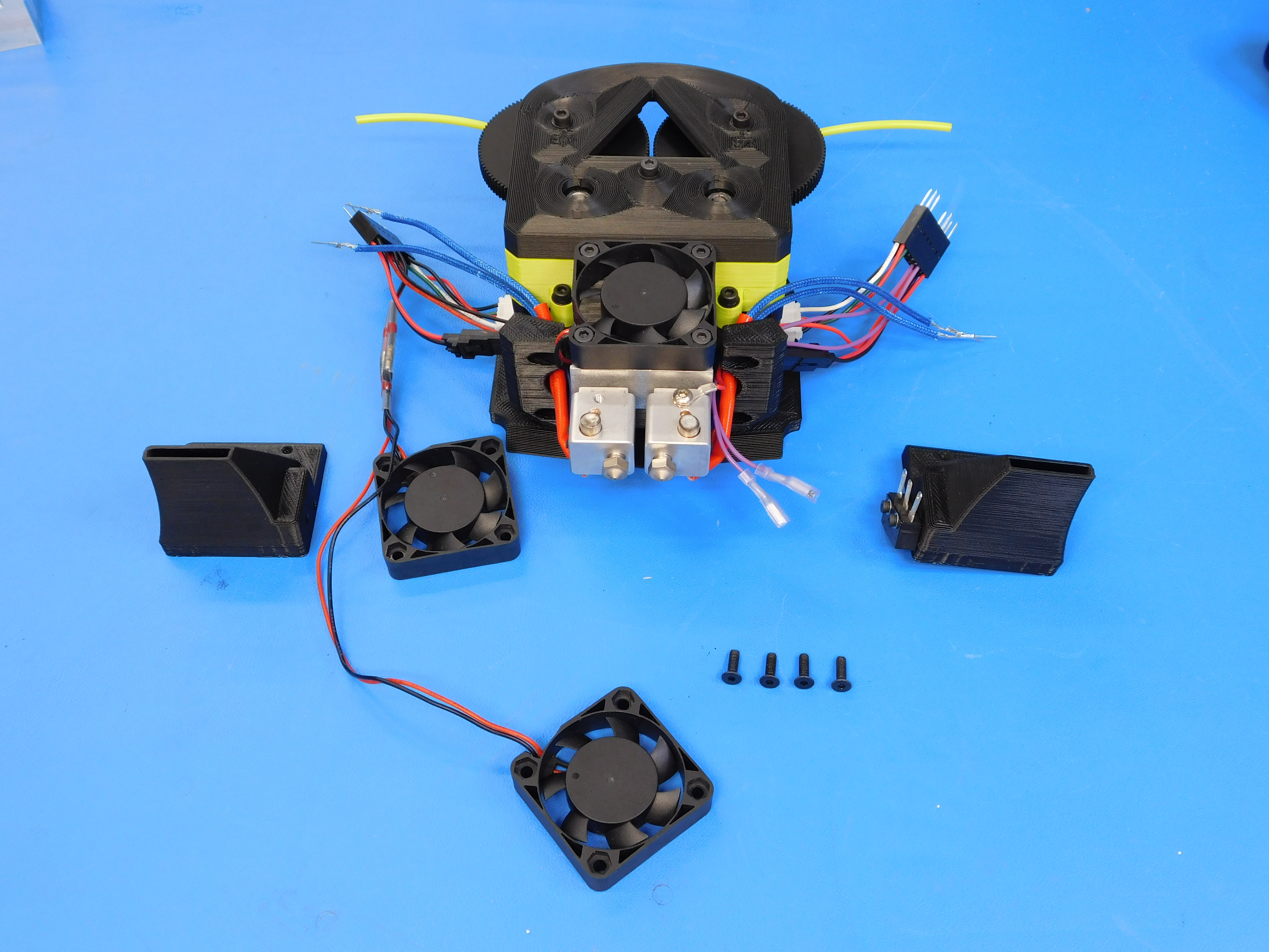
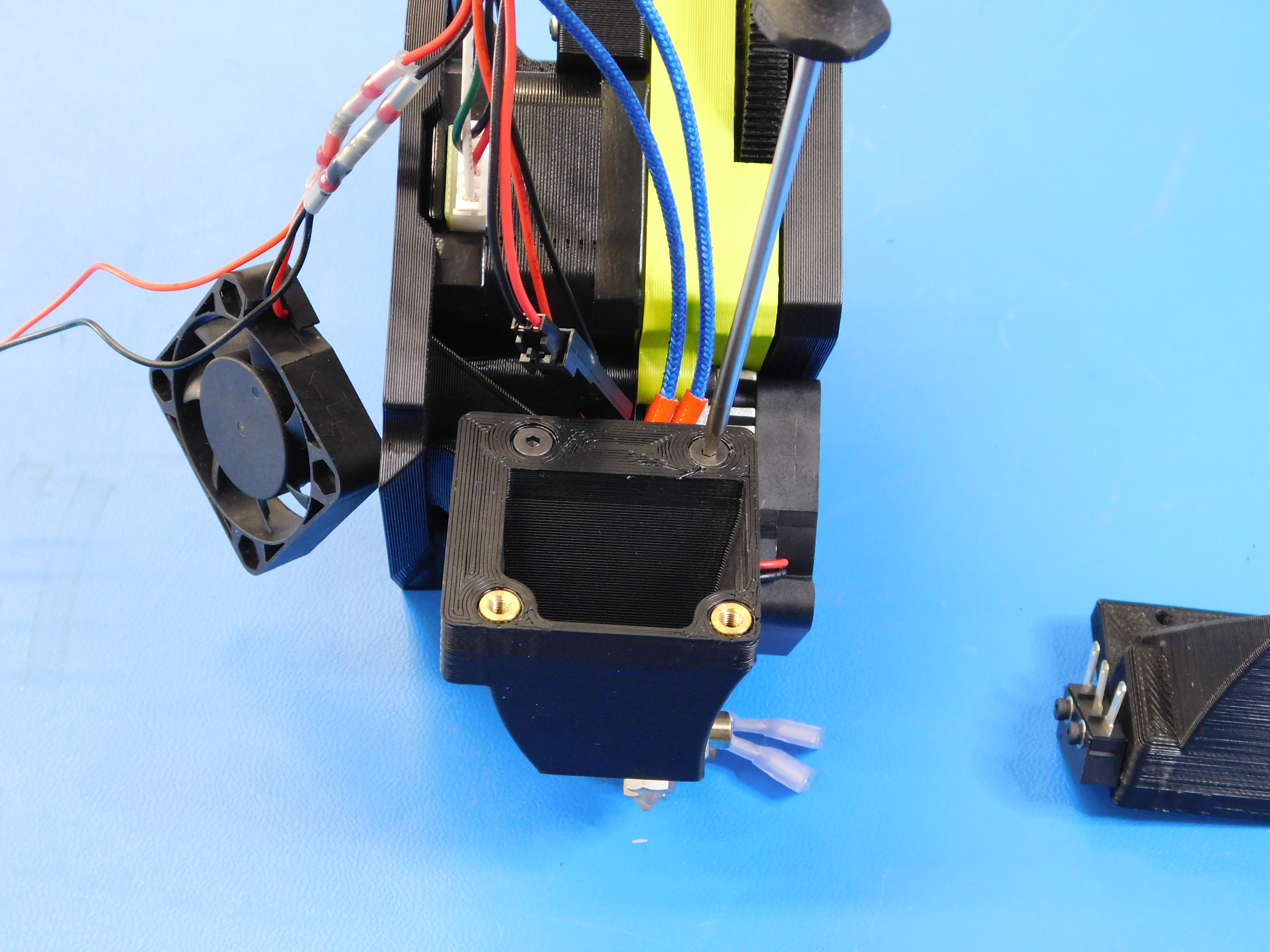
Route the part cooling fan wires as shown.
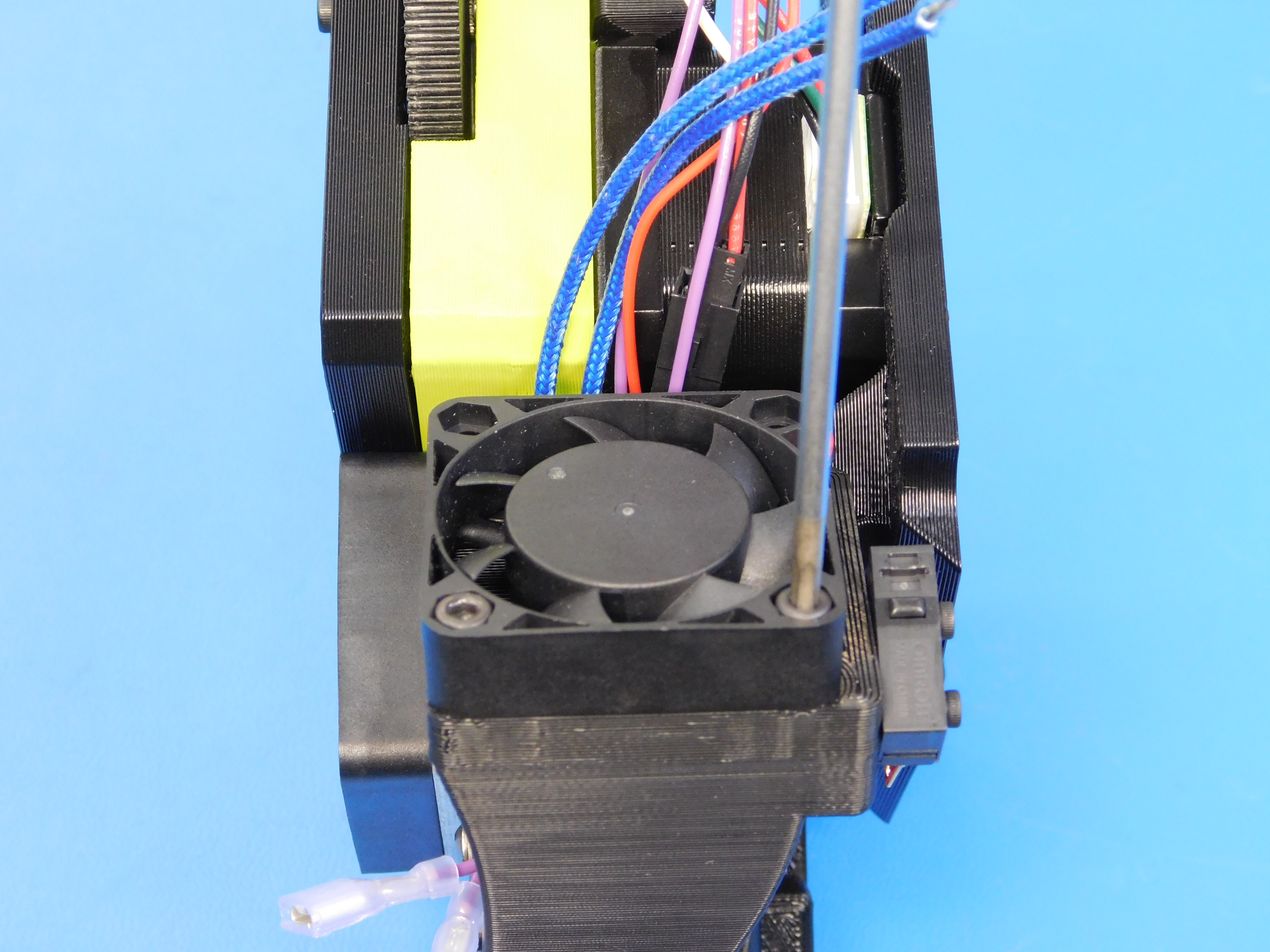
Using four M3 x 12 SHCS [HD-BT0039], fasten the part cooling fans to the fan ducts as shown in the pictures.

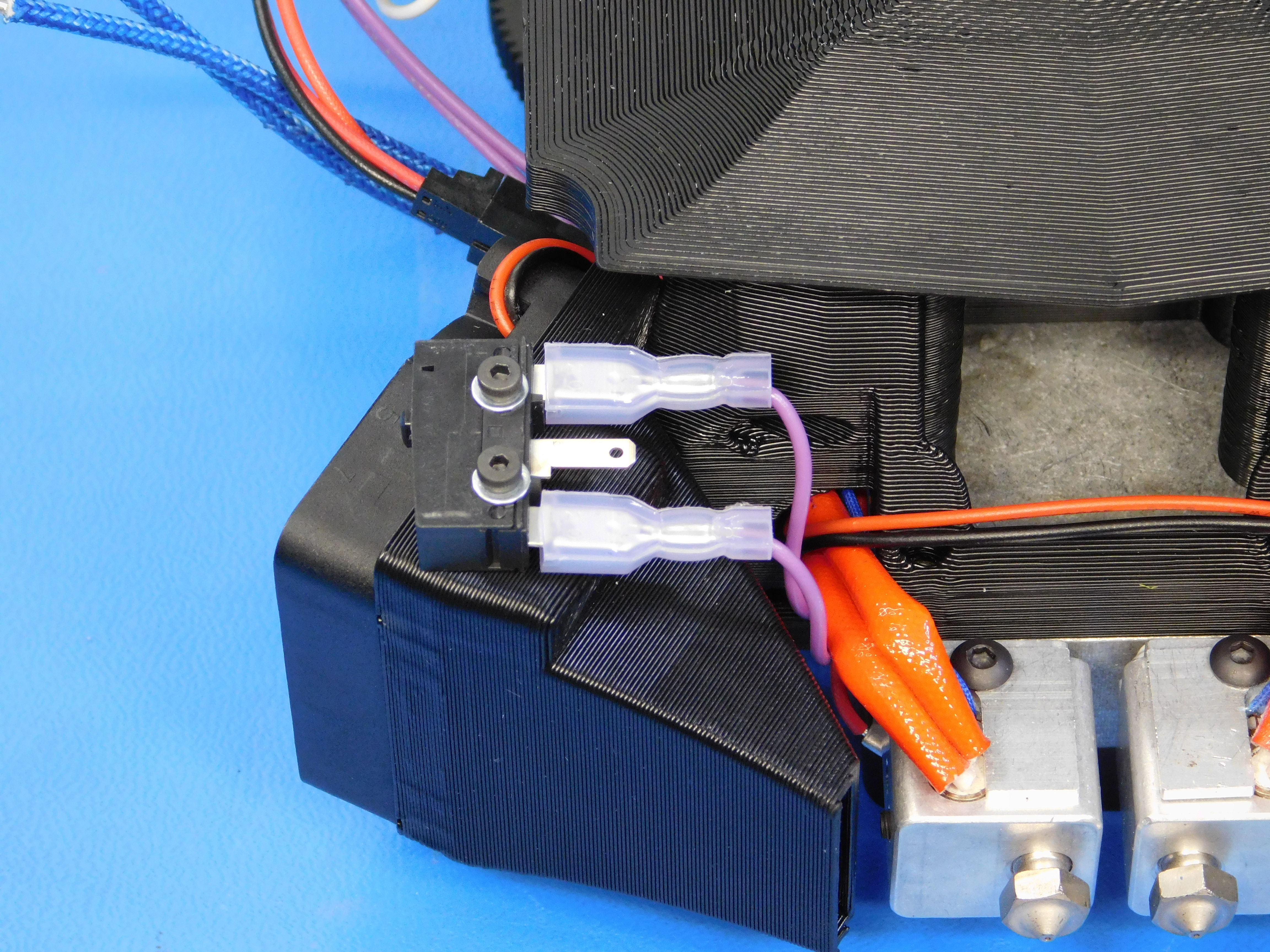
Connect the endstop switch as shown.
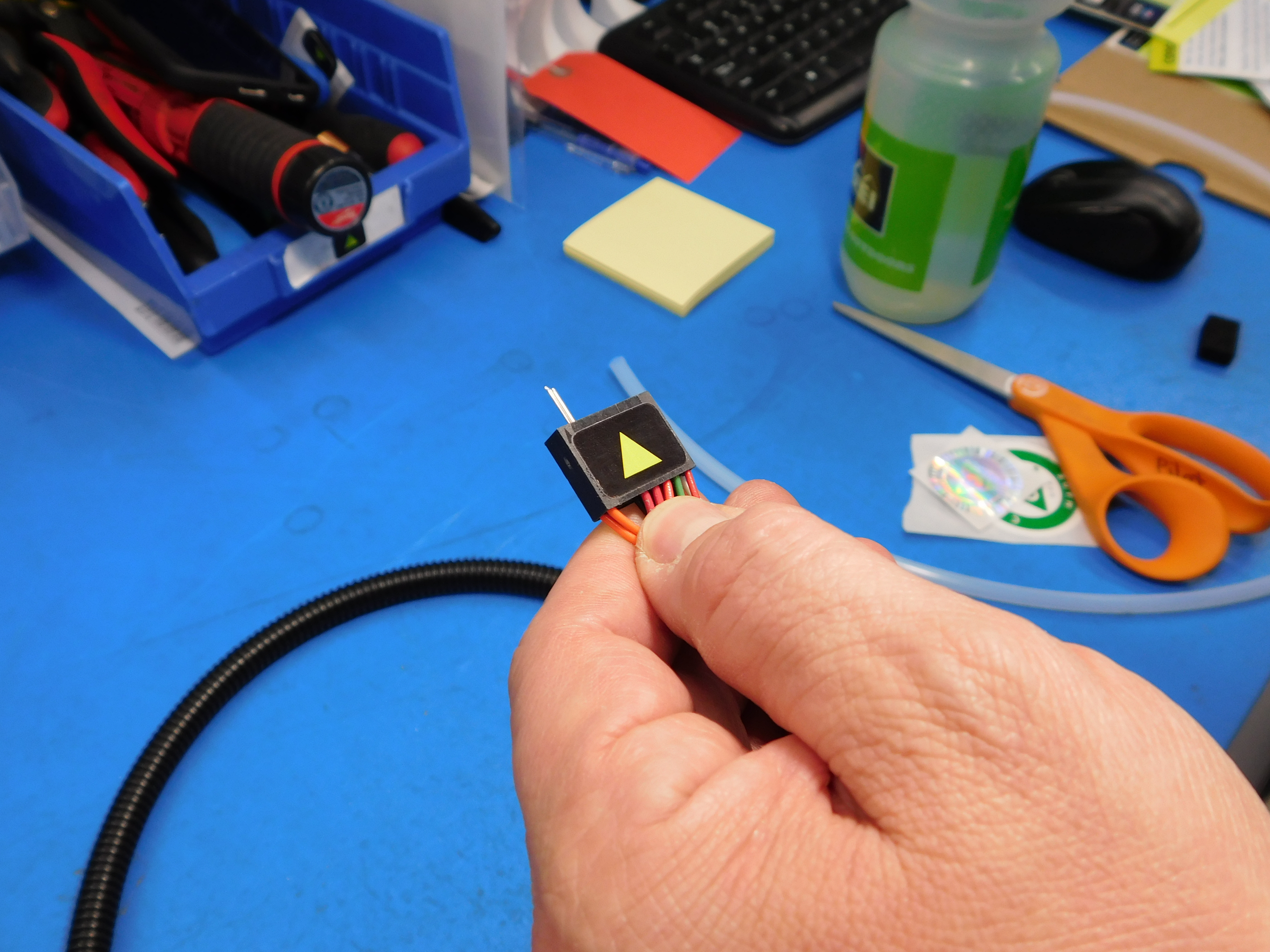
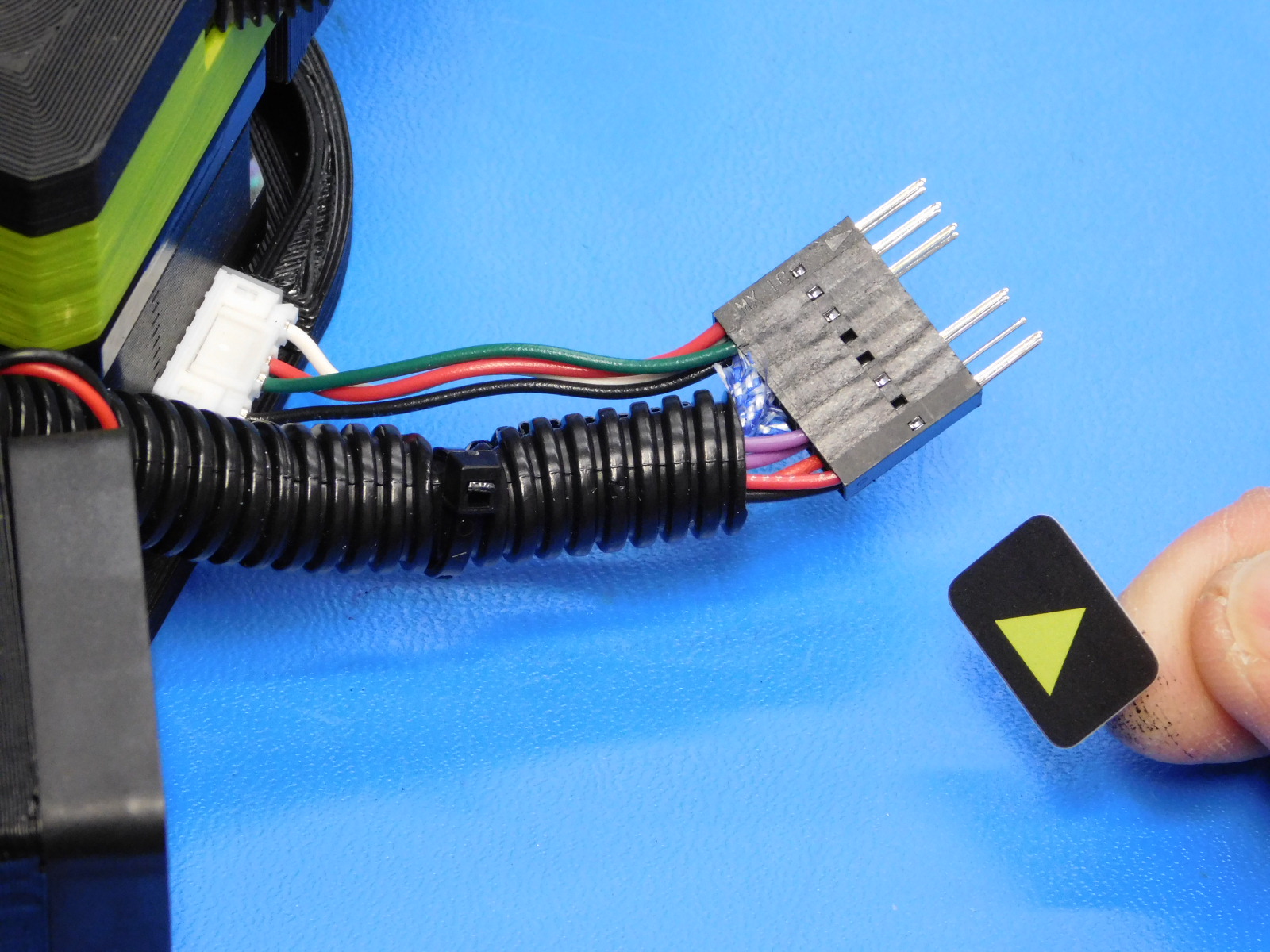
Pin the heater cartridge as shown. The two pins go into the connector in the holes directly adjacent to the stepper motor wires.
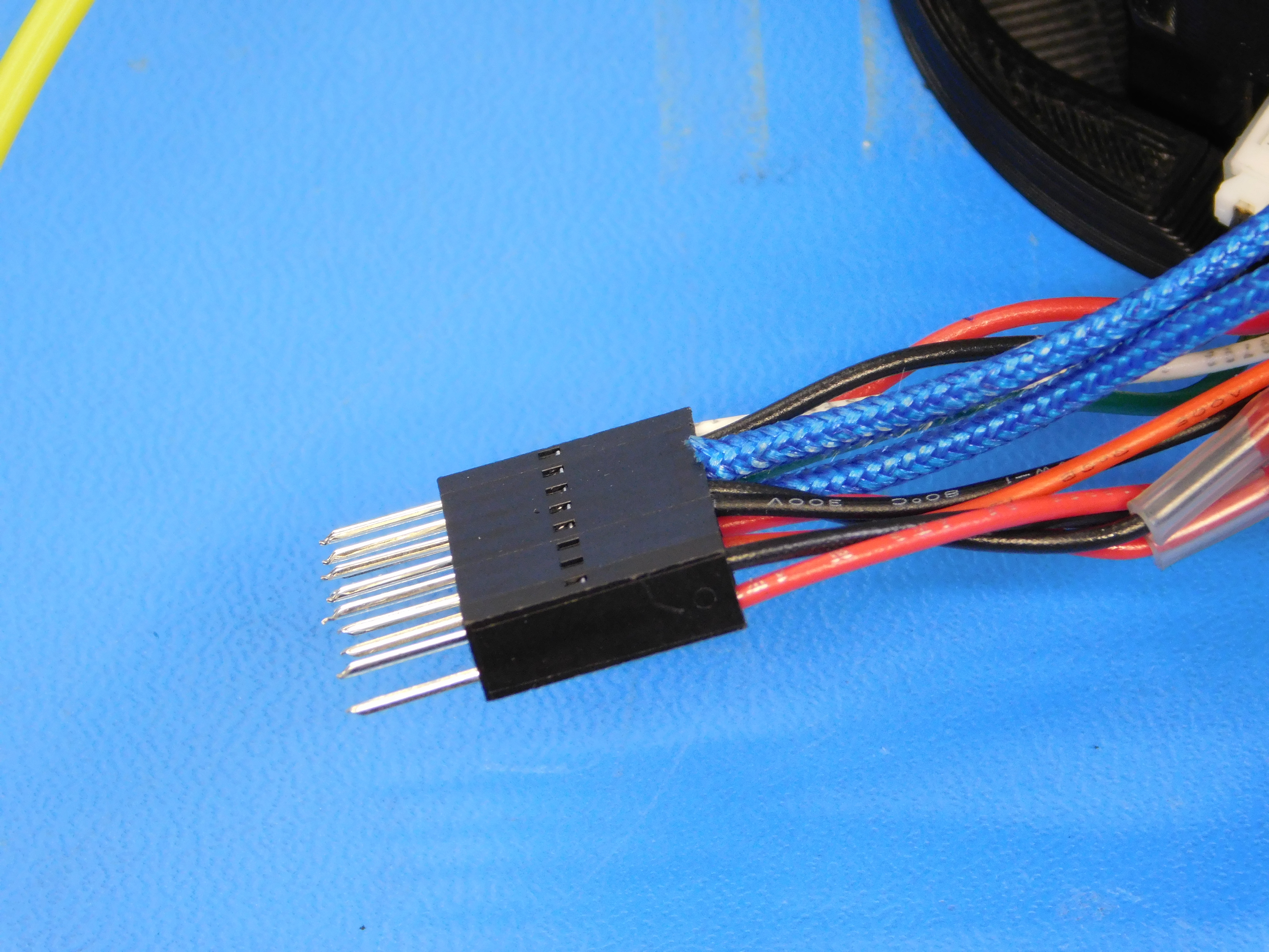
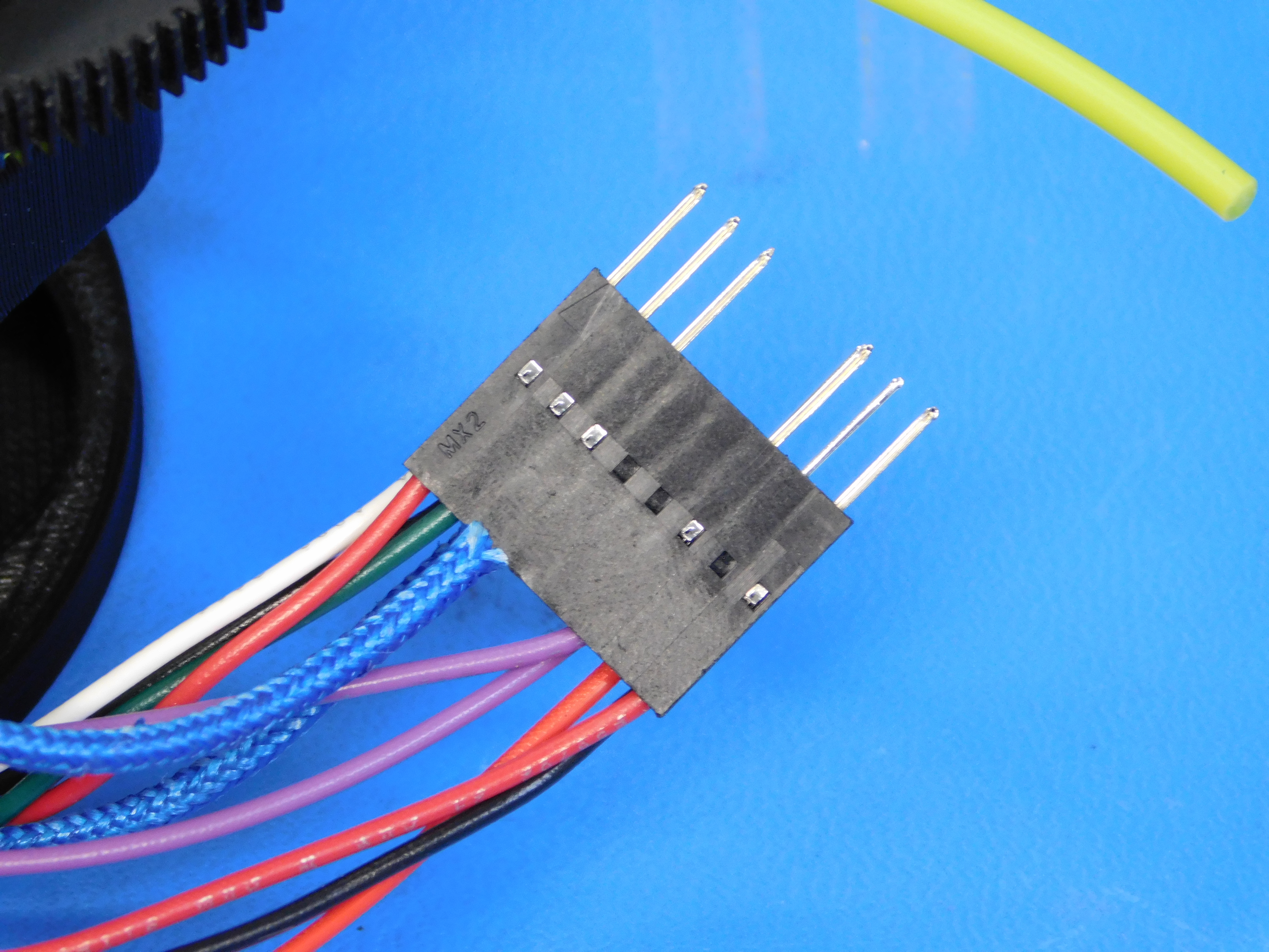
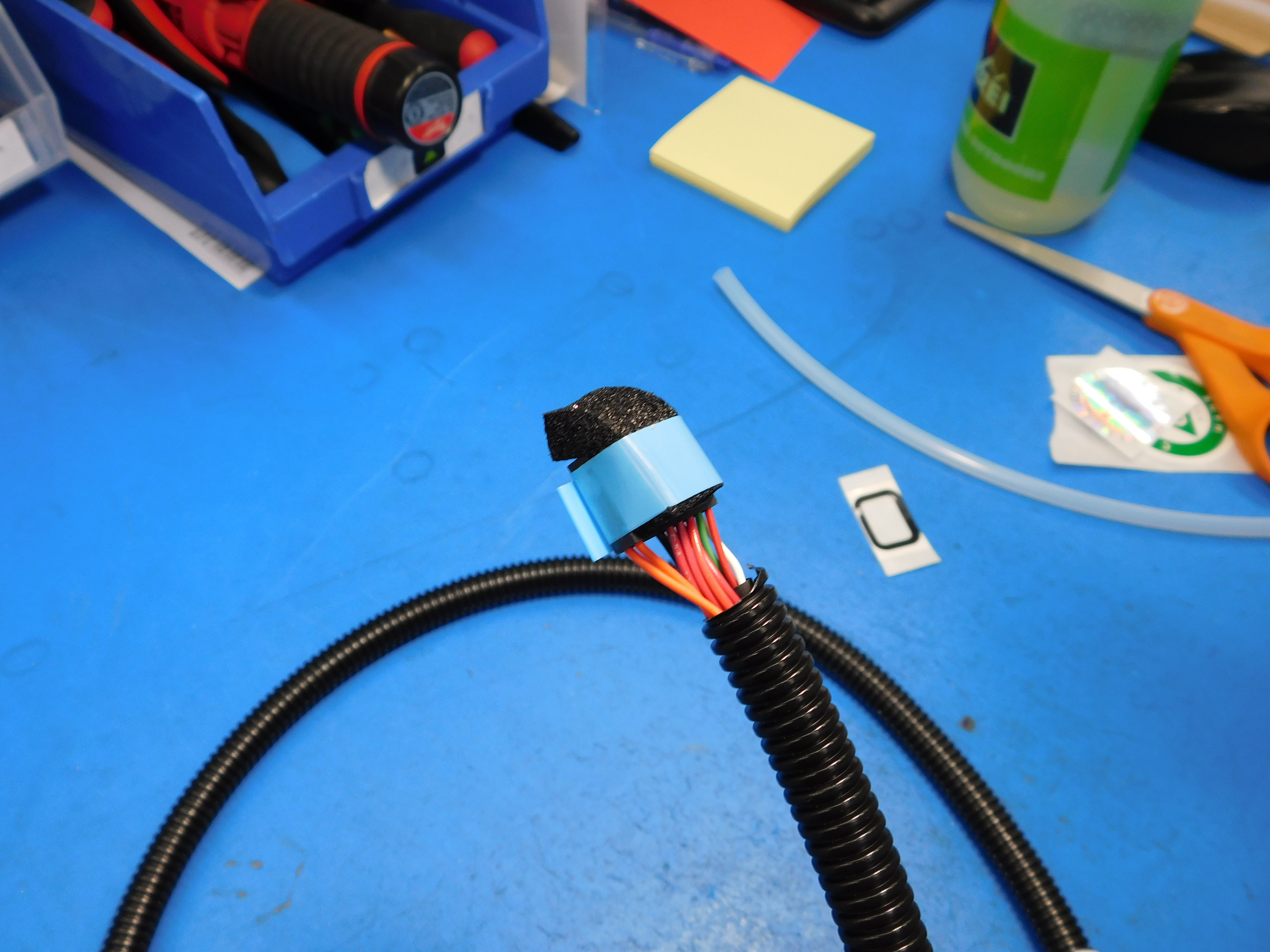
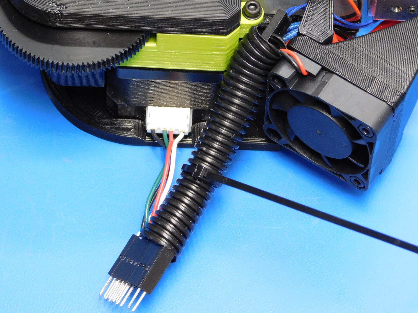
Install the corrugated looming [EL-MS0139] and secure with zip ties [HD-MS0058] as shown in the pictures. Trim the zip ties. Attach direction stickers [DC-LB0104] as shown, making sure that the sticker is on the pin one side of the connector.
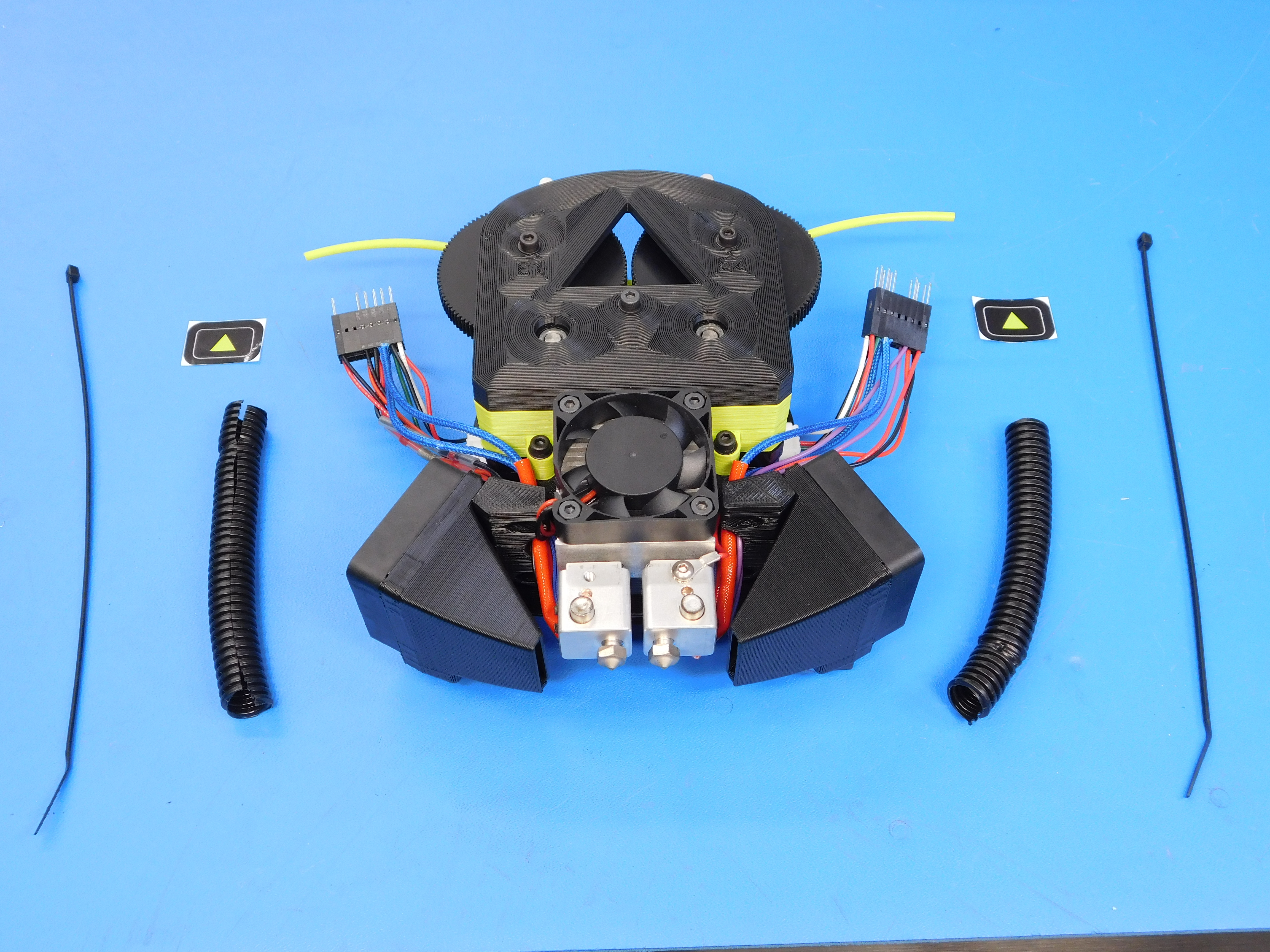
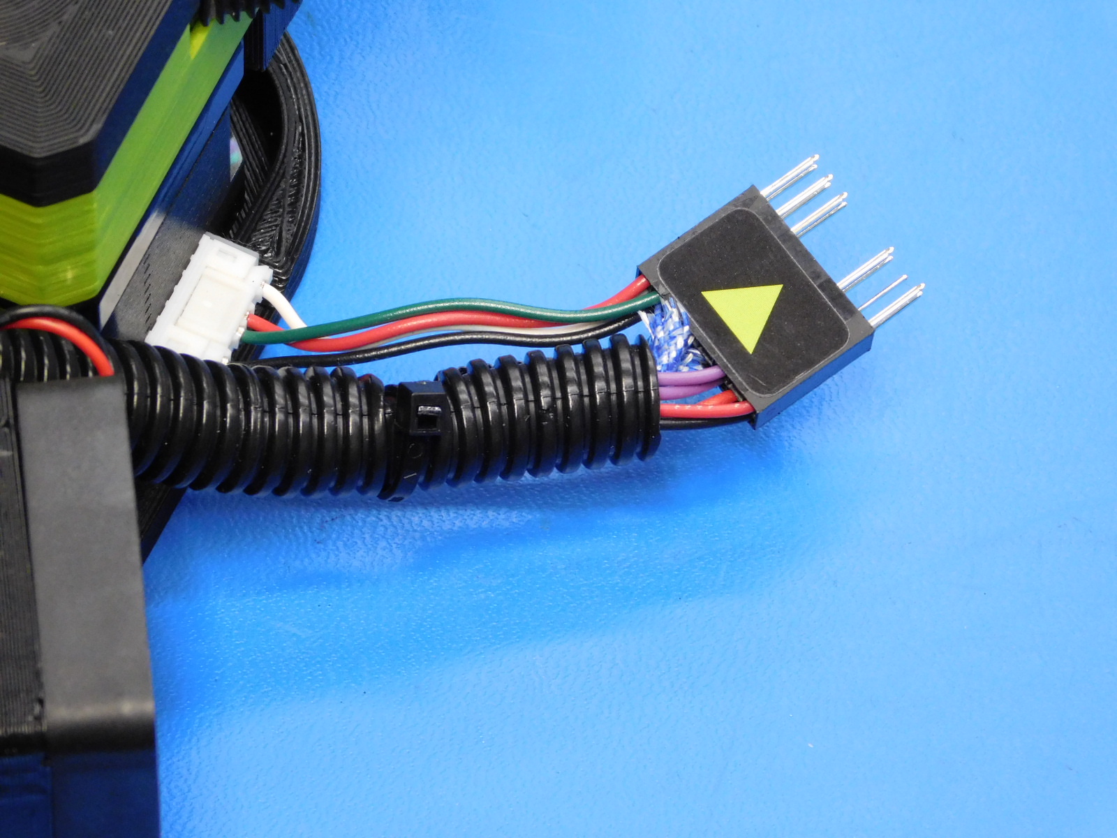
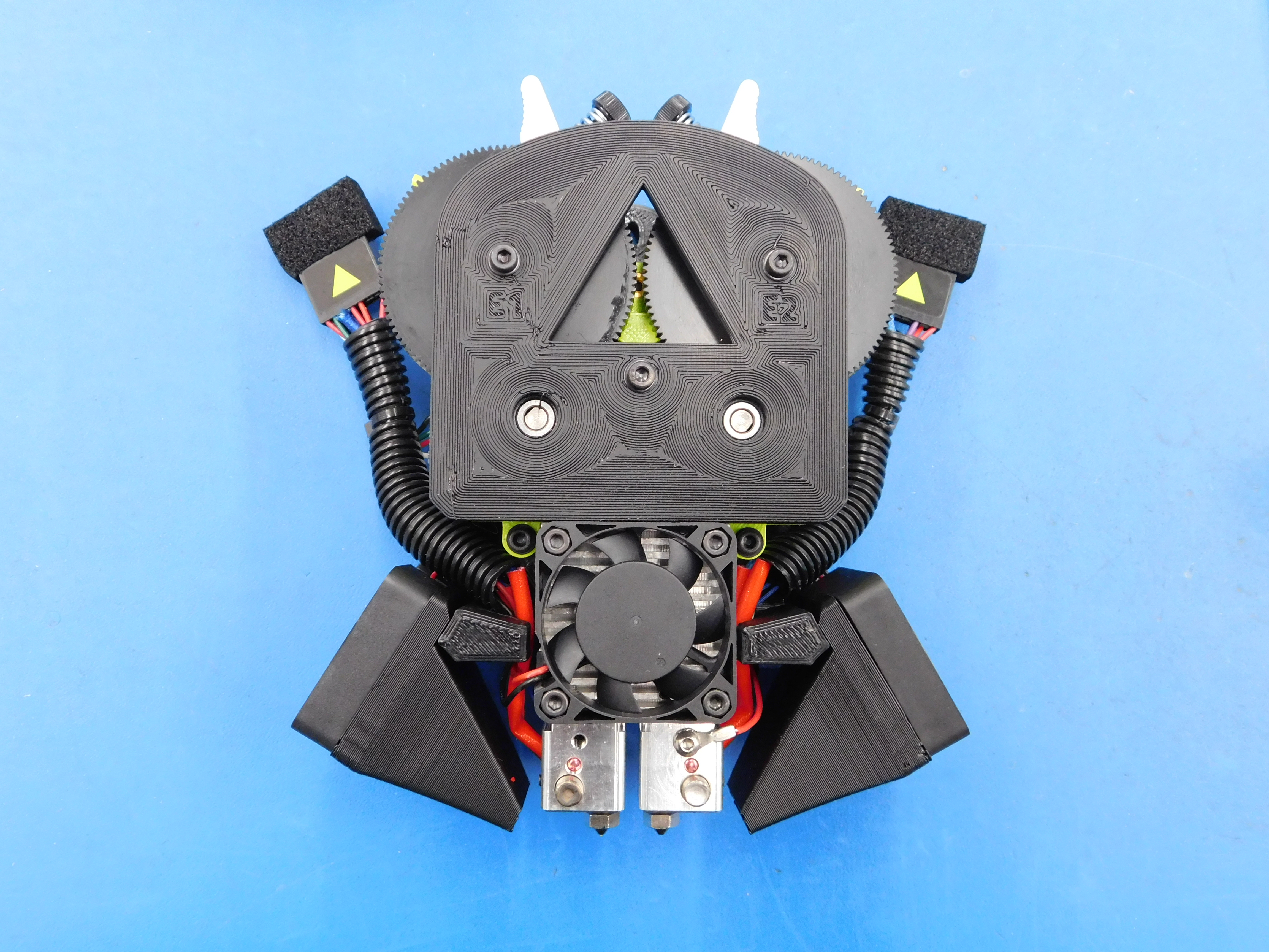
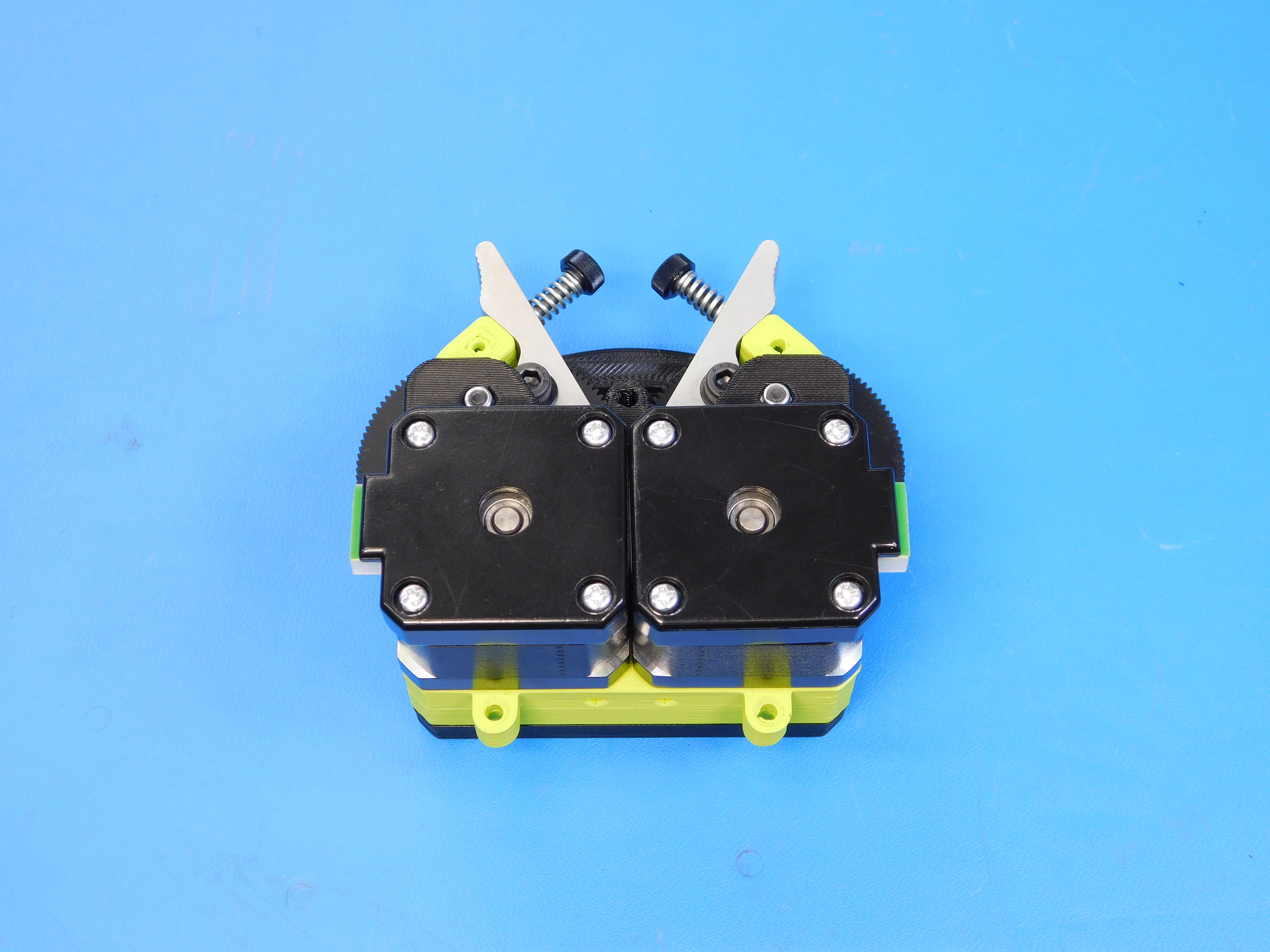
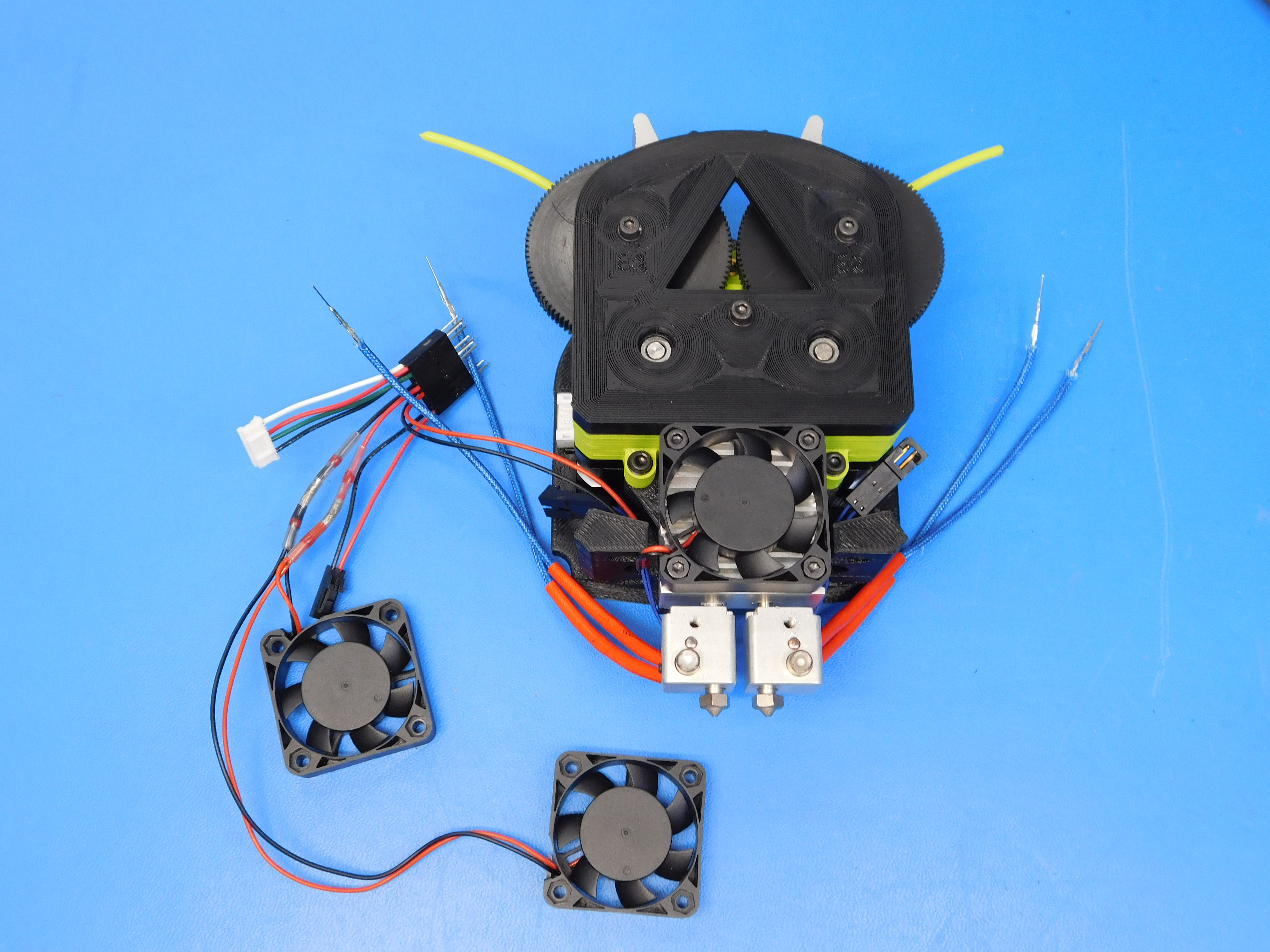
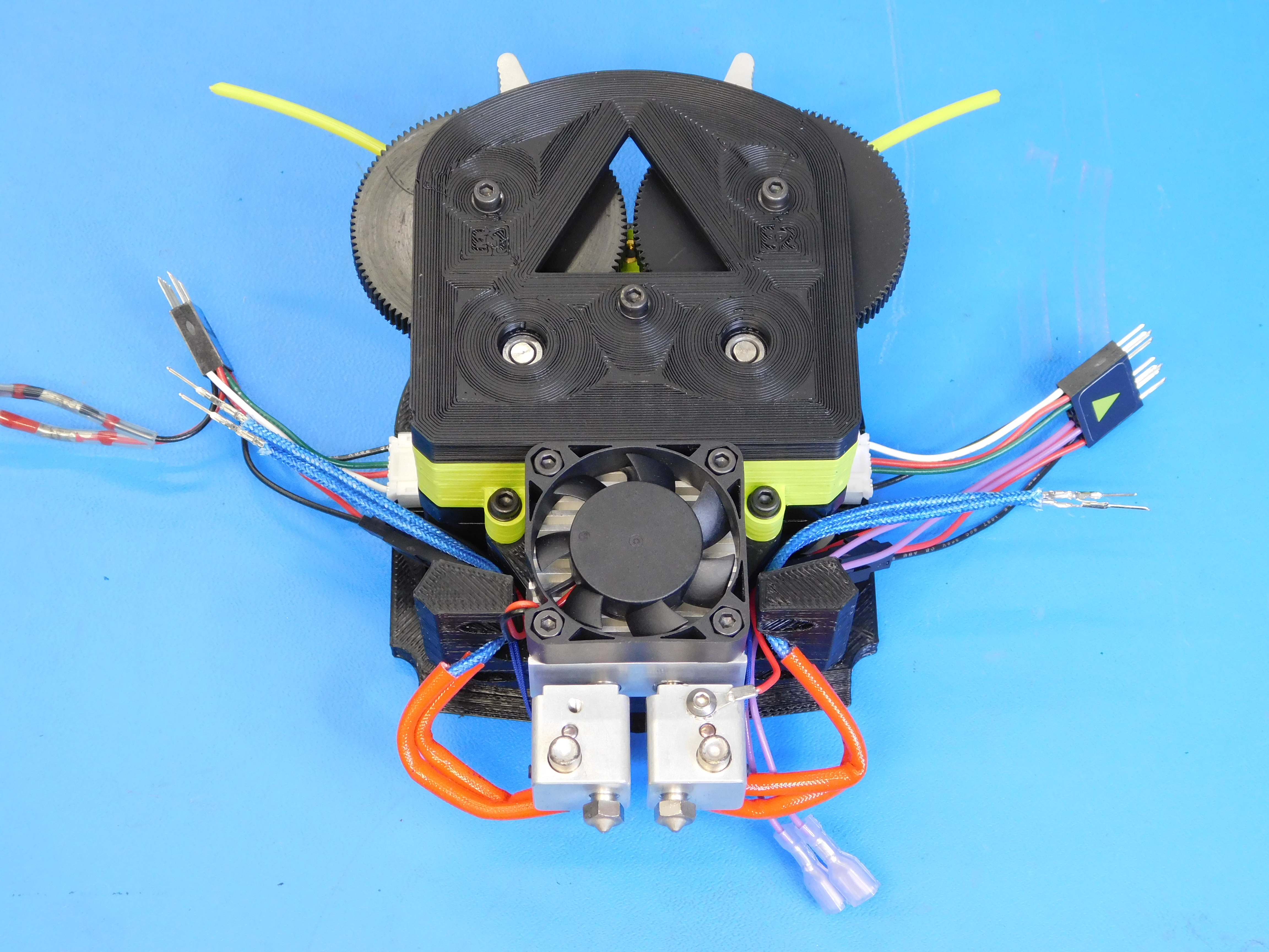
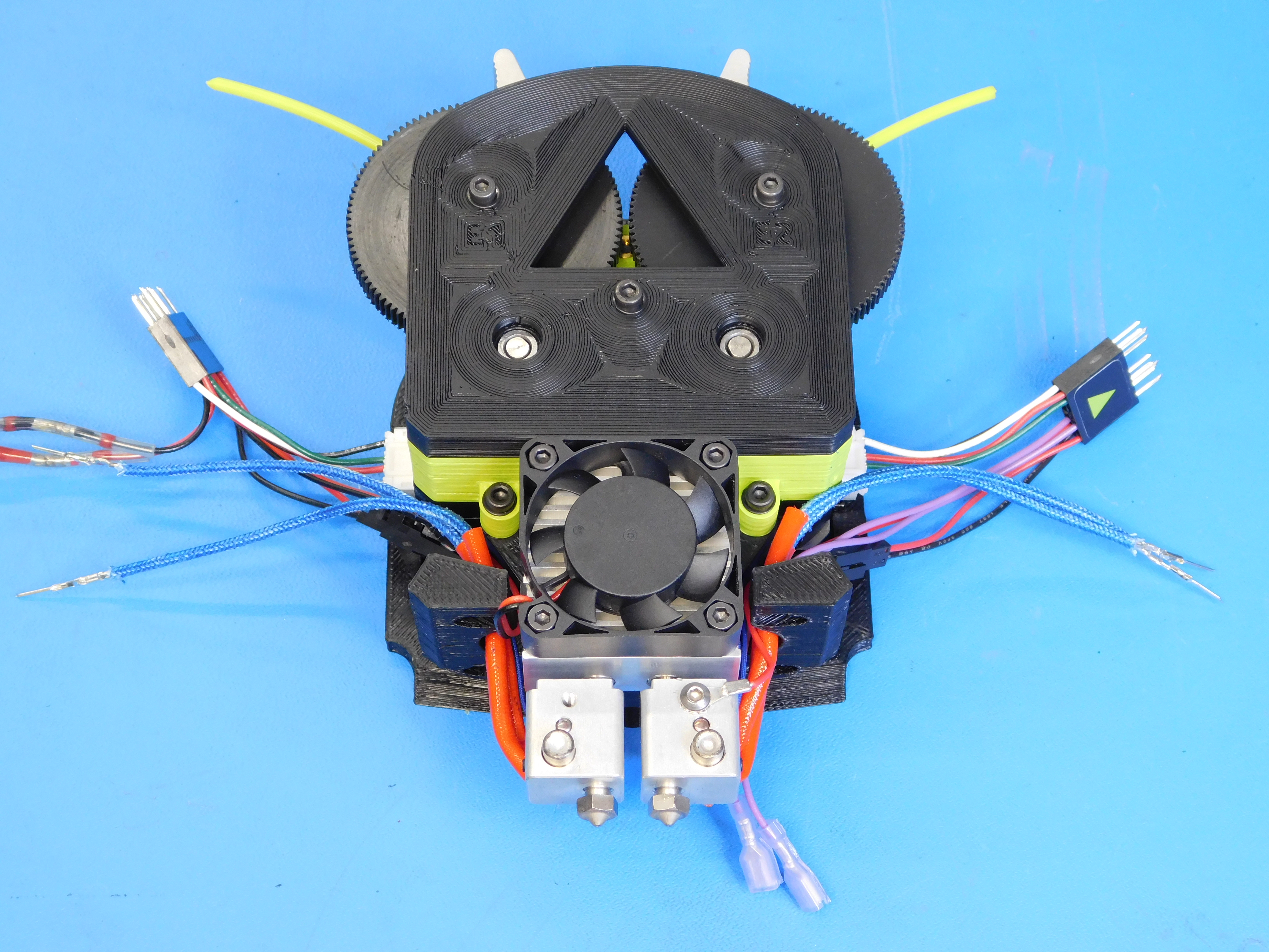
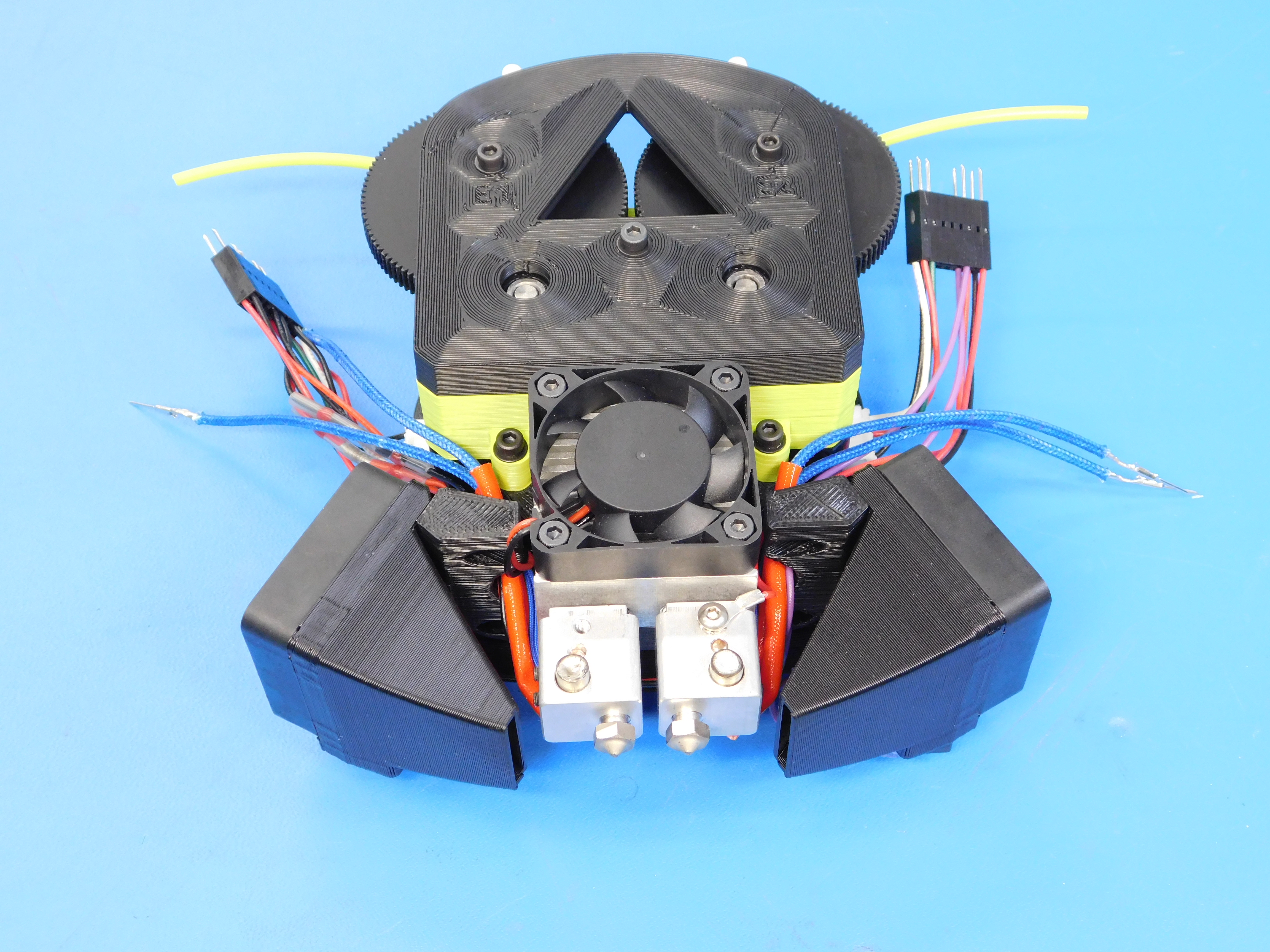
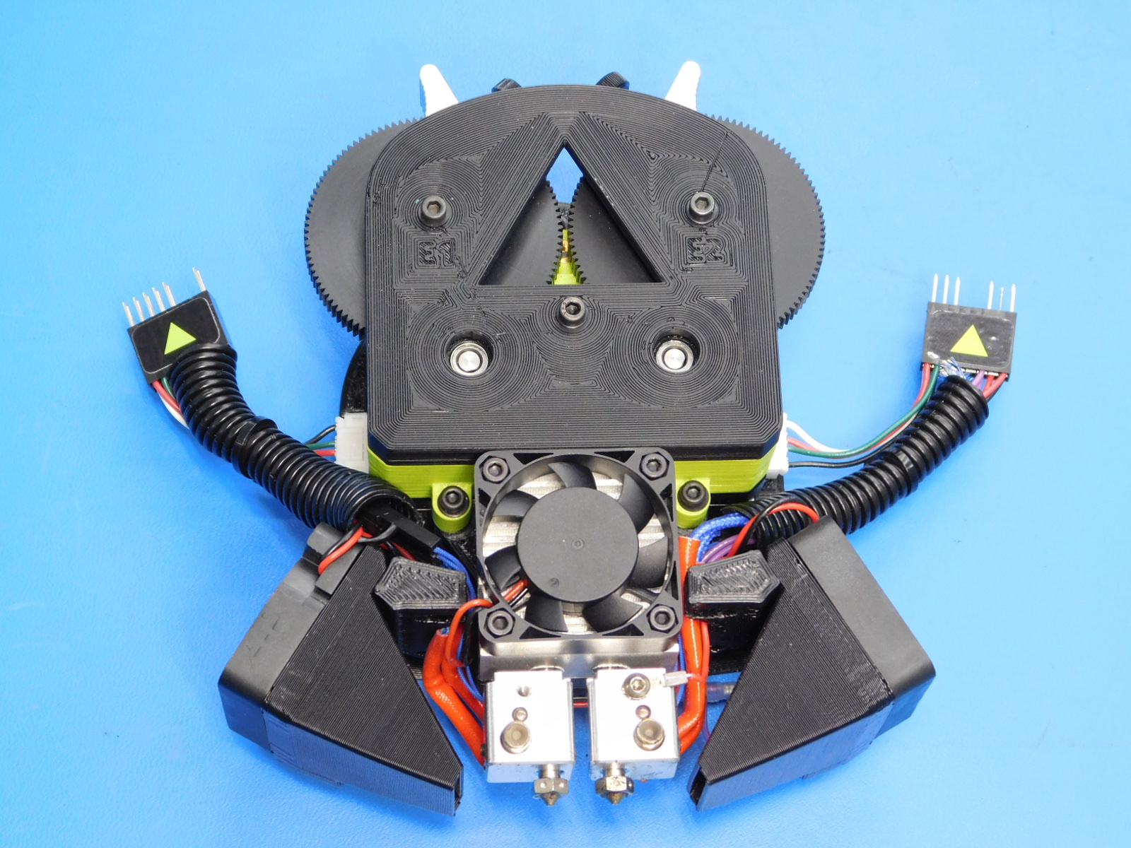
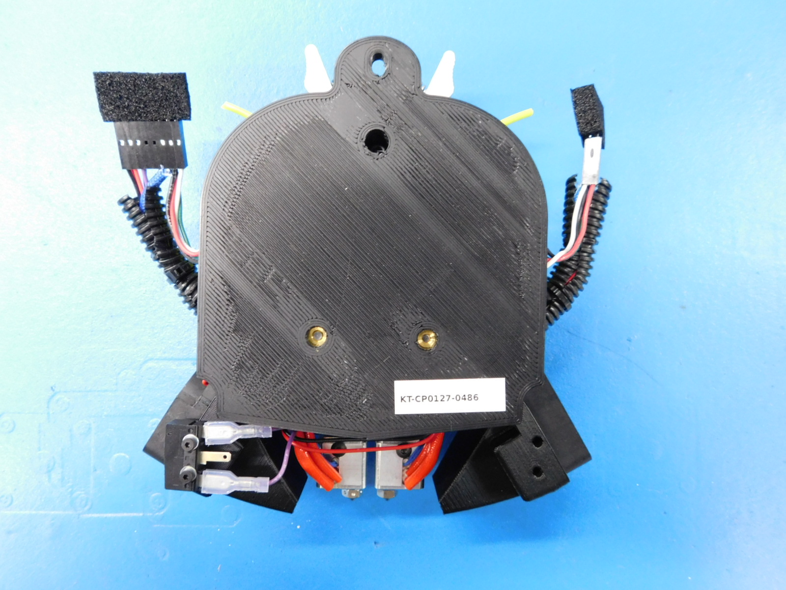
Check to make sure everything is installed correctly, it should look like the picture.
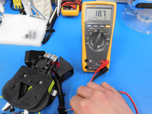
After assembly of the Dual Extruder v3 is complete, it is necessary to verify the electrical properties of the toolhead, namely the heater cartridge and thermistor of E1 and E2
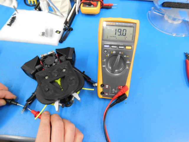
First we will test the resistance value of the heater cartridge of E1 To do so, first set your multimeter to Ohms which is signified by the capital Greek letter Omega. Now touch the probes of your multimeter to pins 5 & 6 individually. Note: Positive or negative probe positions are irrelevant to this test. The display on the multimeter should now show a value around 19 Ohms. Any value between 17.5 and 21.3 Ohms is acceptable, values outside of that range are cause for rejection of the heater cartridge and it should be replaced.
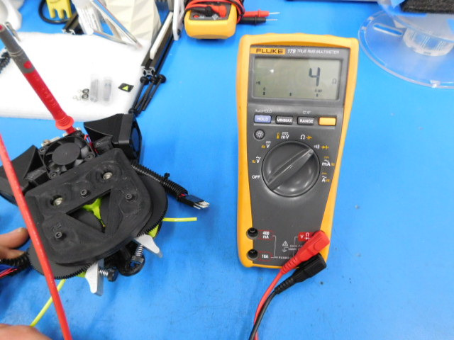
Next we will verify that the heater cartridge of E1 DOES NOT have continuity to the ground circuit. To do so, the multimeter may remain in Ohms mode or be switched to an audible continuity test mode by moving the switch to the symbol representing sound waves. Now touch one probe to the heater block, and the other to pins 5 & 6 individually. Note: Positive or negative probe positions are irrelevant to this test. Whether probing pin 5 or 6, the multimeter display should remain at 0 and no audible alarm should sound. This indicates that there is no continuity between either lead of the heater cartridge and the toolheads ground circuit. If the multimeter display reads anything but 0, or an audible alarm is heard during either half of this test, the heater cartridge must be rejected and replaced.
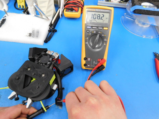
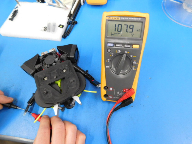
Next we will perform the same tests for the thermistor of E1 To do so, first set your multimeter to Ohms which is signified by the capital Greek letter Omega. Now touch the probes of your multimeter to pins 15 & 16 individually. Note: Positive or negative probe positions are irrelevant to this test. The display on the multimeter should now show a value between 80 and 120 K Ohms. Pay close attention to the units displayed on the multimeter's display; the letter 'K' should be displayed to the right of the value. If a reading is given in Ohms or Mega Ohms (indicated by the letter 'M' to the right of the value displayed) or the kOhms reading is too low (values displayed as 1.xx or similar) or otherwise outside of the range stated above, the thermistor must be rejected and replaced.
Next we will verify that the thermistor of E1 DOES NOT have continuity to the ground circuit. To do so, the multimeter may remain in Ohms mode or be switched to an audible continuity test mode by moving the switch to the symbol representing sound waves. Now touch one probe to the heater block, and the other to pins 15 & 16 individually. Note: Positive or negative probe positions are irrelevant to this test. Whether probing pin 15 or 16, the multimeter display should remain at 0 and no audible alarm should sound. This indicates that there is no continuity between either lead of the thermistor and the toolhead's ground circuit. If the multimeter display reads anything but 0, or an audible alarm is heard during either half of this test, the thermistor must be rejected and replaced.
Now its time to test E2
First we will test the resistance value of the heater cartridge of E2 To do so, first set your multimeter to Ohms which is signified by the capital Greek letter Omega. Now touch the probes of your multimeter to pins 5 & 6 individually. Note: Positive or negative probe positions are irrelevant to this test. The display on the multimeter should now show a value around 19 Ohms. Any value between 17.5 and 21.3 Ohms is acceptable, values outside of that range are cause for rejection of the heater cartridge and it should be replaced.
Next we will verify that the heater cartridge of E2 DOES NOT have continuity to the ground circuit. To do so, the multimeter may remain in Ohms mode or be switched to an audible continuity test mode by moving the switch to the symbol representing sound waves. Now touch one probe to the heater block, and the other to pins 5 & 6 individually. Note: Positive or negative probe positions are irrelevant to this test. Whether probing pin 5 or 6, the multimeter display should remain at 0 and no audible alarm should sound. This indicates that there is no continuity between either lead of the heater cartridge and the toolheads ground circuit. If the multimeter display reads anything but 0, or an audible alarm is heard during either half of this test, the heater cartridge must be rejected and replaced.
Next we will perform the same tests for the thermistor of E2 To do so, first set your multimeter to Ohms which is signified by the capital Greek letter Omega. Now touch the probes of your multimeter to pins 15 & 16 individually. Note: Positive or negative probe positions are irrelevant to this test. The display on the multimeter should now show a value between 80 and 120 K Ohms. Pay close attention to the units displayed on the multimeter's display; the letter 'K' should be displayed to the right of the value. If a reading is given in Ohms or Mega Ohms (indicated by the letter 'M' to the right of the value displayed) or the kOhms reading is too low (values displayed as 1.xx or similar) or otherwise outside of the range stated above, the thermistor must be rejected and replaced.
Next we will verify that the thermistor of E2 DOES NOT have continuity to the ground circuit. To do so, the multimeter may remain in Ohms mode or be switched to an audible continuity test mode by moving the switch to the symbol representing sound waves. Now touch one probe to the heater block, and the other to pins 15 & 16 individually. Note: Positive or negative probe positions are irrelevant to this test. Whether probing pin 15 or 16, the multimeter display should remain at 0 and no audible alarm should sound. This indicates that there is no continuity between either lead of the thermistor and the toolhead's ground circuit. If the multimeter display reads anything but 0, or an audible alarm is heard during either half of this test, the thermistor must be rejected and replaced.
To finalize this test, verify that the zero sense line (ground circuit) has continuity to the nozzle. This test is best performed in the audible continuity mode. Touch one probe to the nozzle or heater block, and the other to pin 14 on the toolhead's connector. Note: Positive or negative probe positions are irrelevant to this test. An audible alarm should sound indicating that continuity is present. If so, the toolhead has passed electrical testing and may proceed to final extrusion testing. Congratulations!
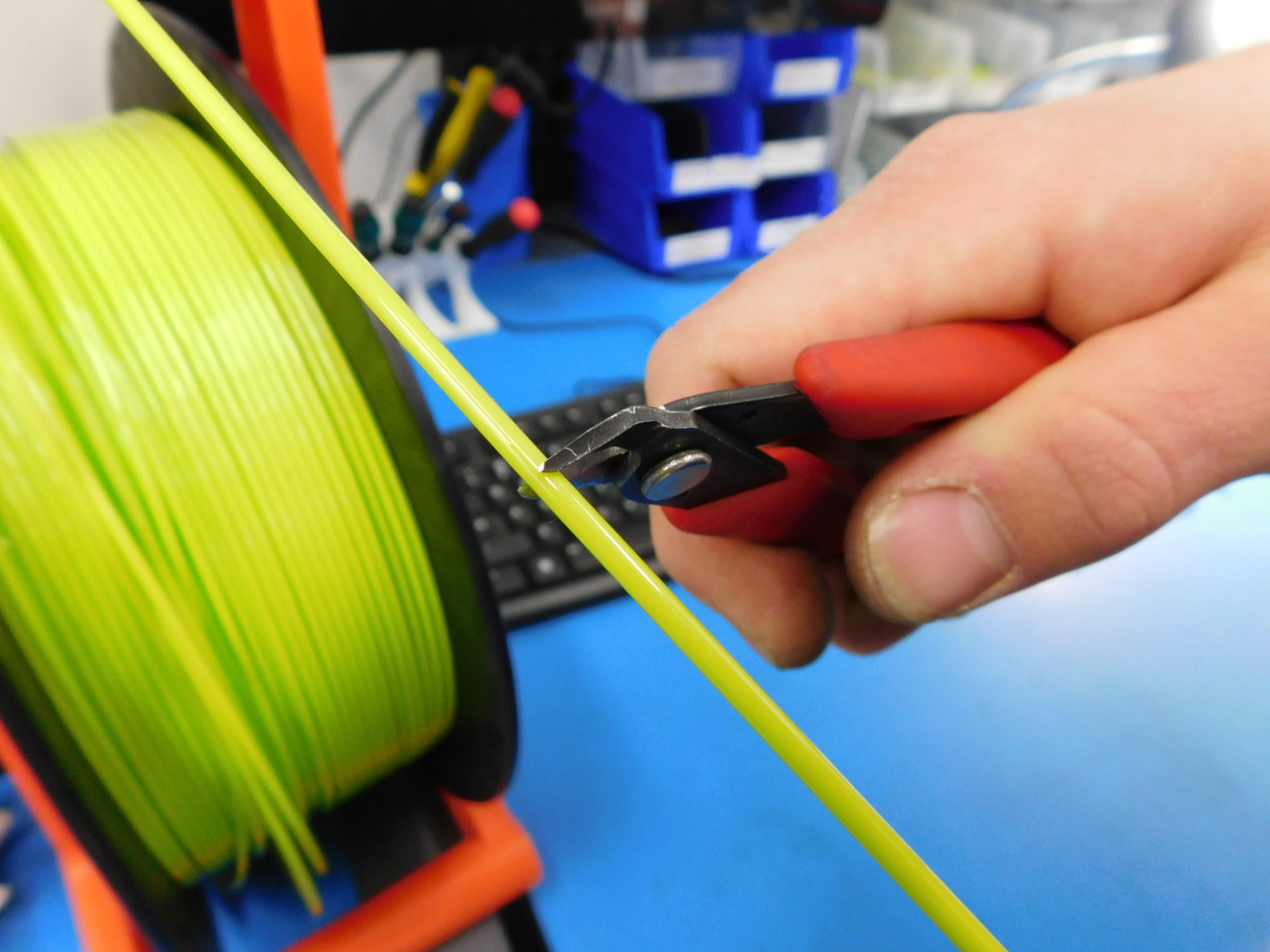
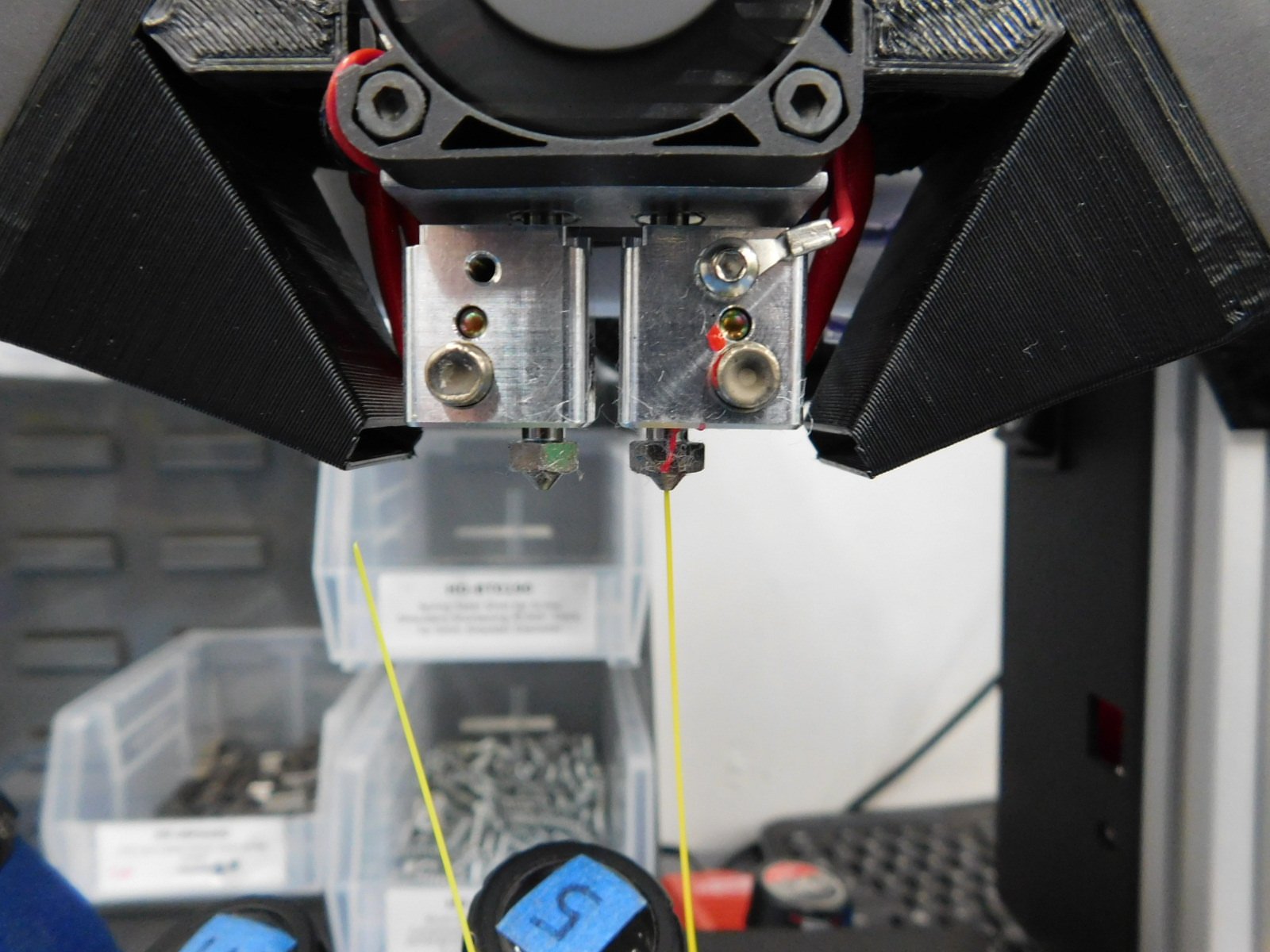
First, Cut PLA filament to about 200mm in length. Then Insert the filament in to both hotends.
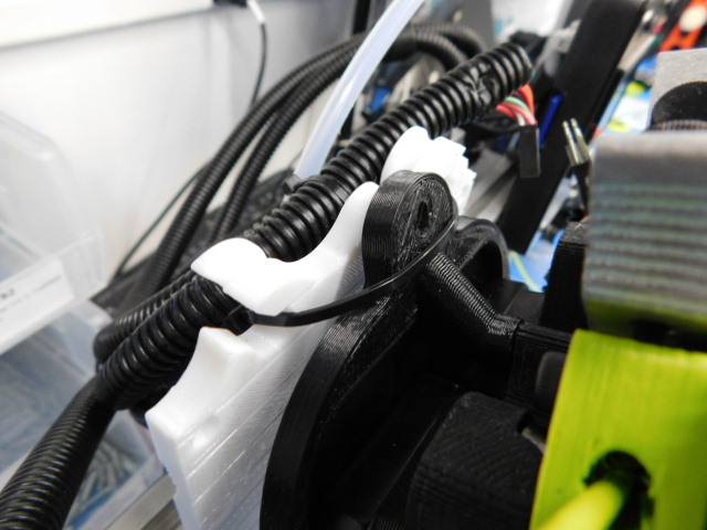
Attach V3 Dual by sliding the top up into the ziptie. Once this is complete, place the extruder flush against the X-carriage and let it settle into the X-Carriage.
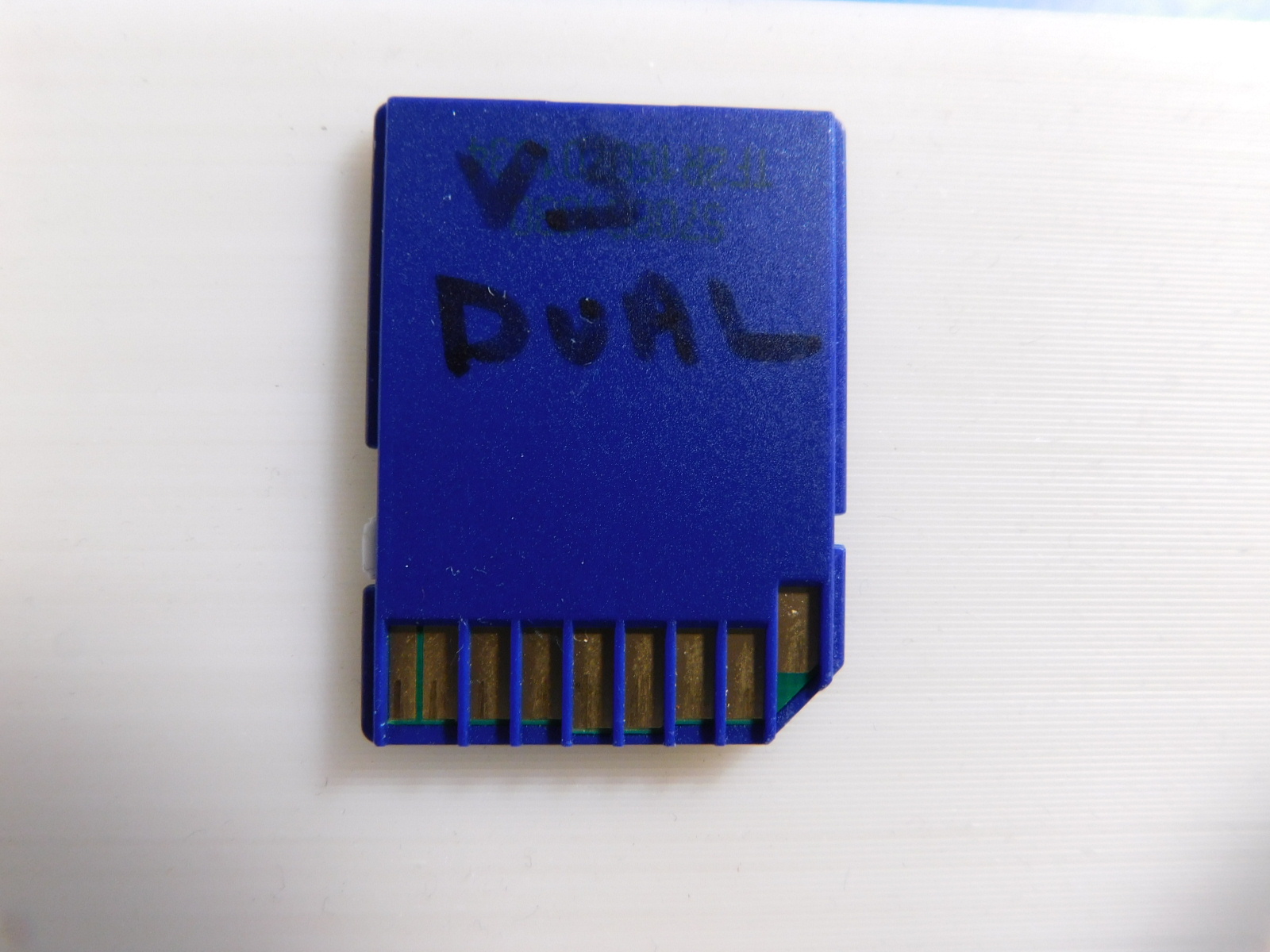
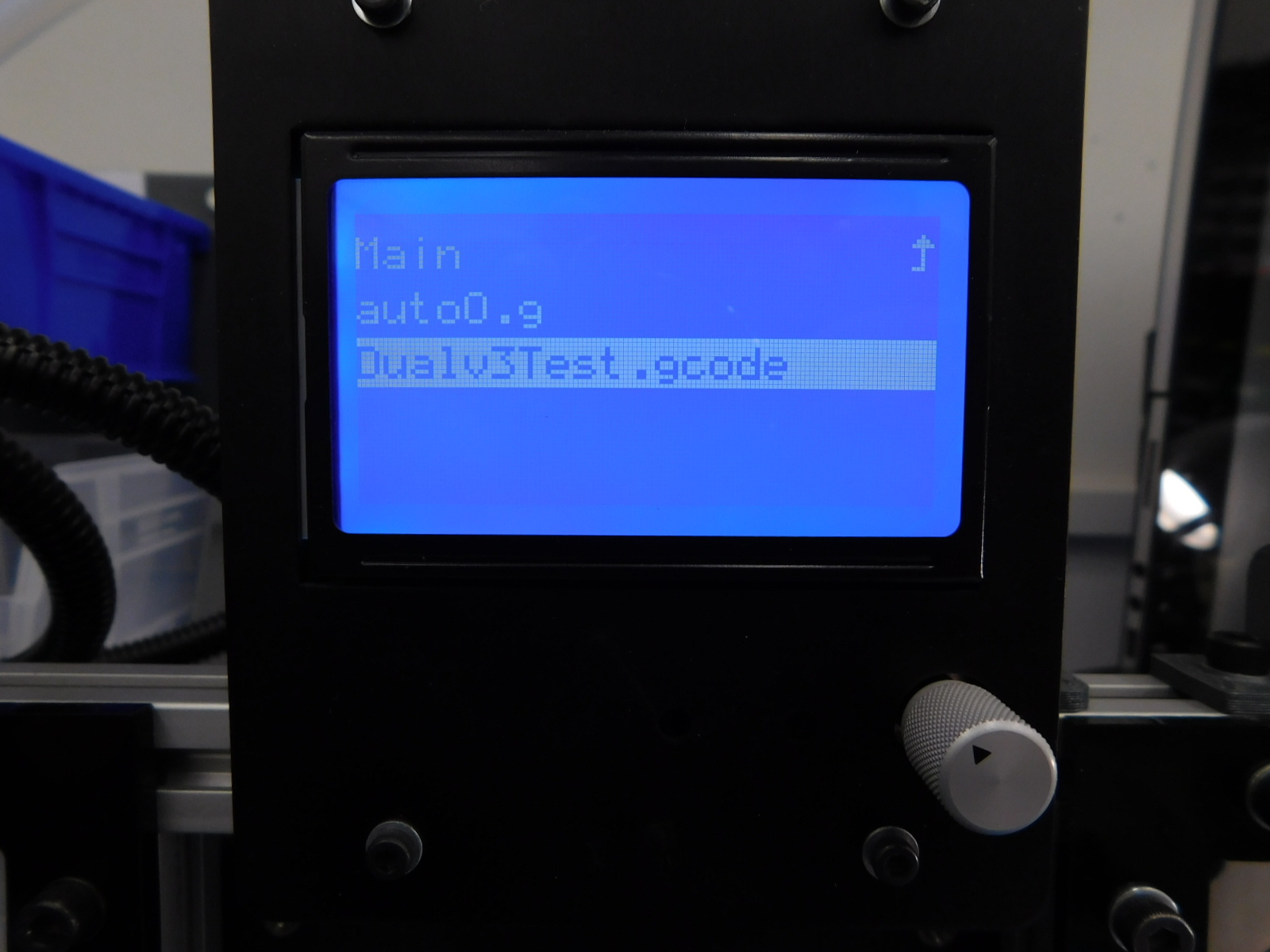
Be sure to check the correct SD card is in the tester. The SD card you should be using is labeled "V3 Dual"
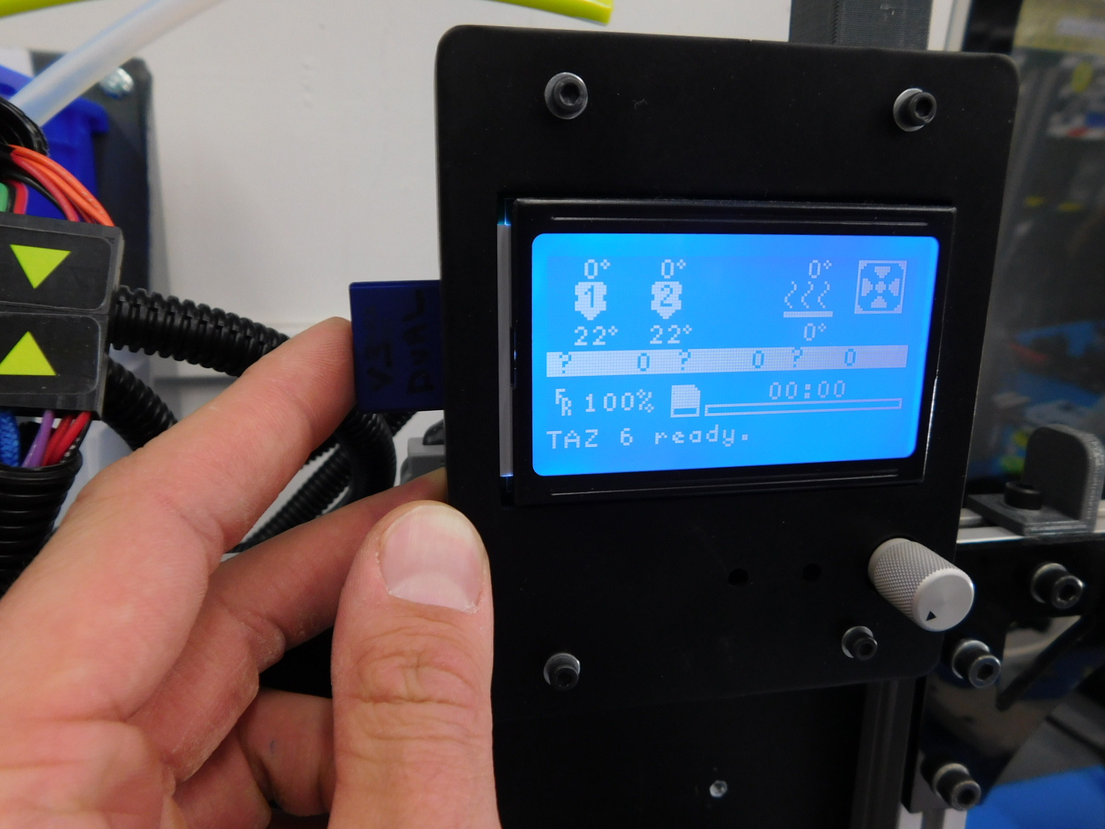
Select the Proper Gcode, Which is labeled "Dualv3Test". This will begin to test the fans first with a three cycle test. Confirm all fans are spinning freely and without excessive noise. Keep in mind the heatsink fan should constantly be on.
Confirm All fans are spinning freely and with out excessive noise. Keep in mind the heatsink fan should constantly be on The hotends will not heat up during this test.
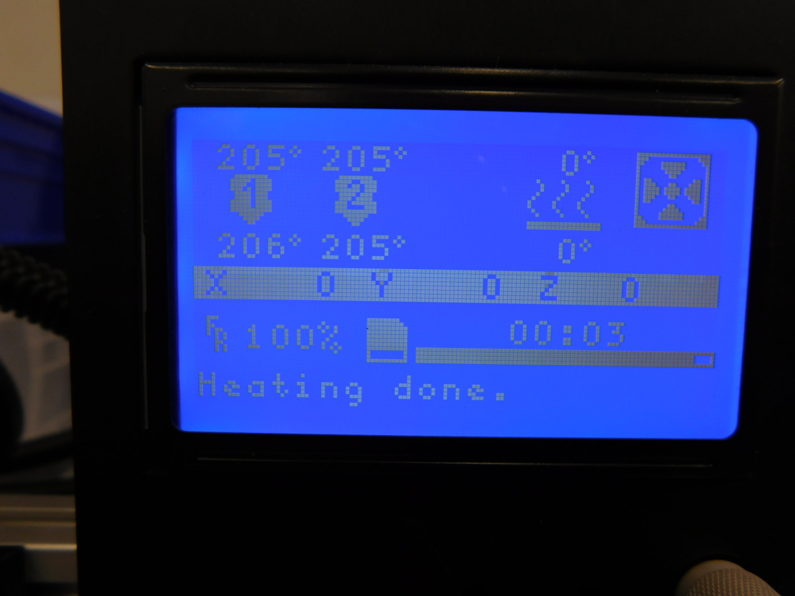
Verify the hotends heat up without big jumps in temperature. The V3 Dual should heat to 205C without any THERMAL ERRORS, MAXTEMP ERRORS, or MINTEMP ERRORS
Verify gear movement once the test starts. The left gear should be moving clock-wise without skipping/clicking, The right gear should be moving counter-clockwise without skipping/clicking.
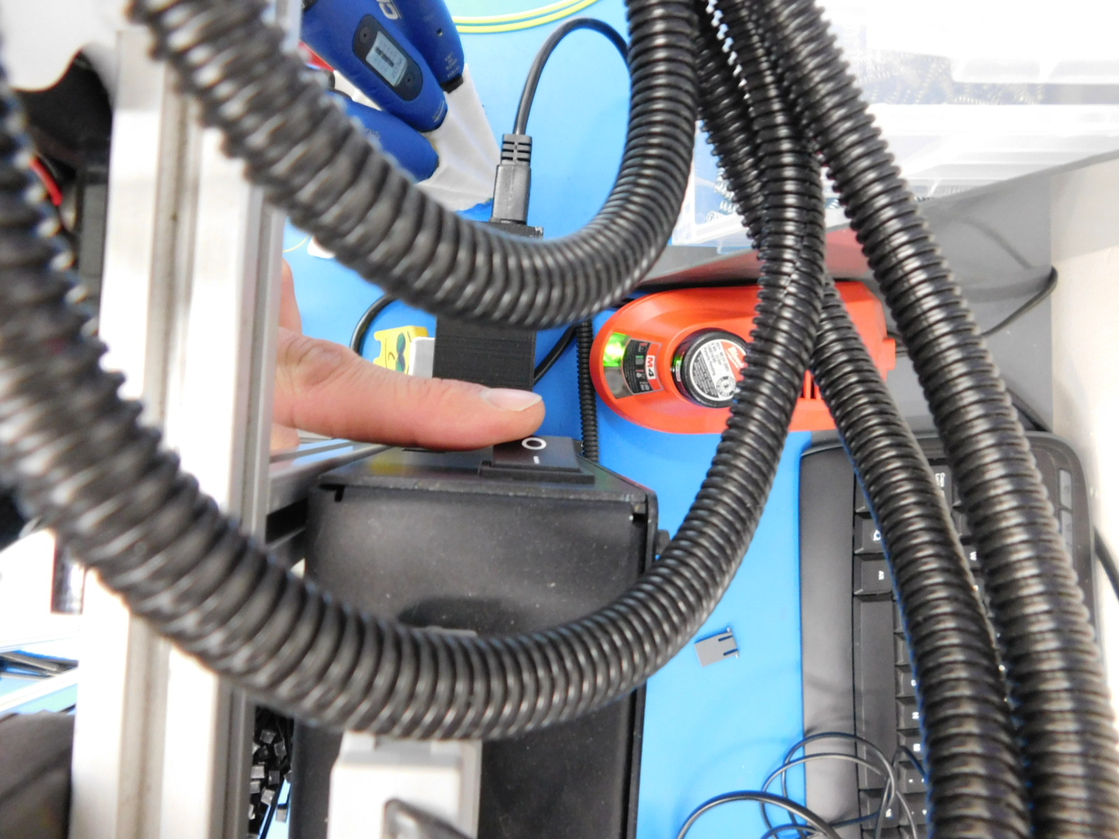
Be sure to turn off tester before unplugging. Unplugging while on could damage the tester.
If the tool head passes the test, put a serial number label sticker on it.
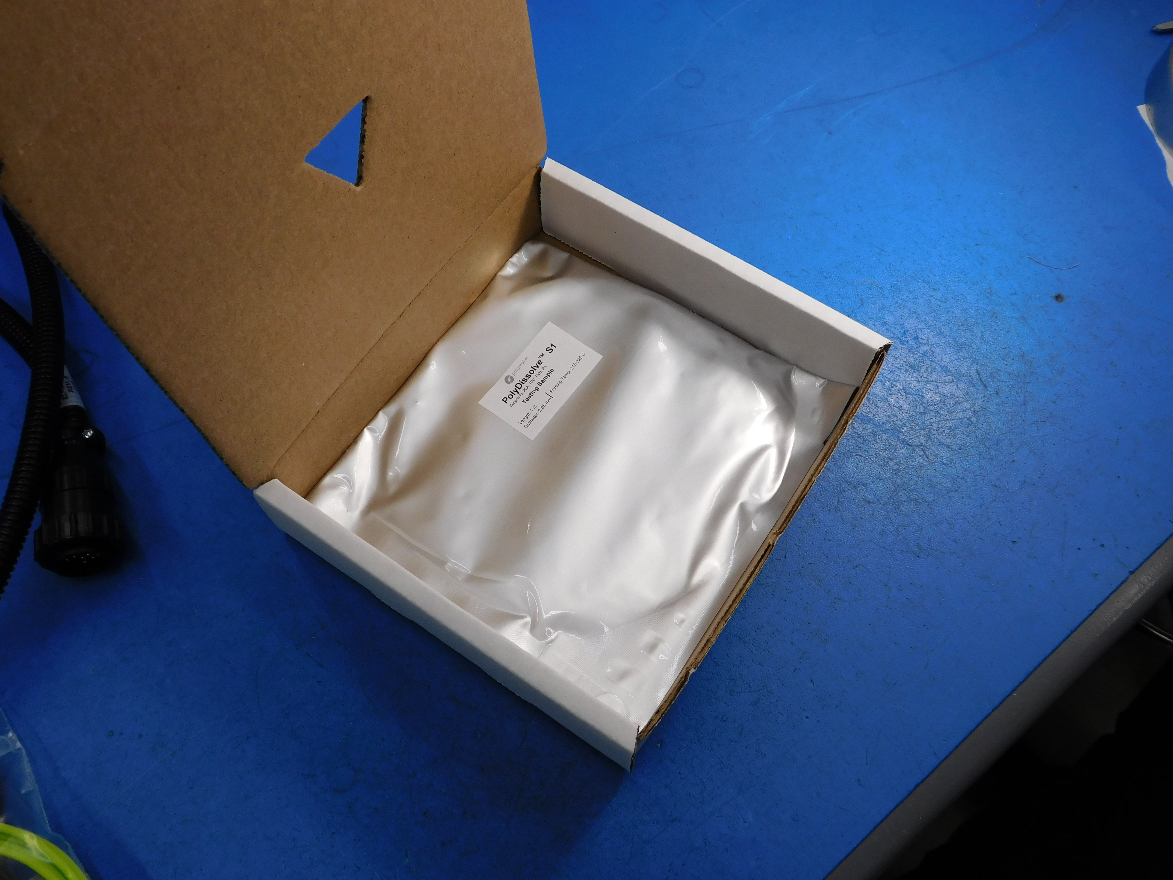
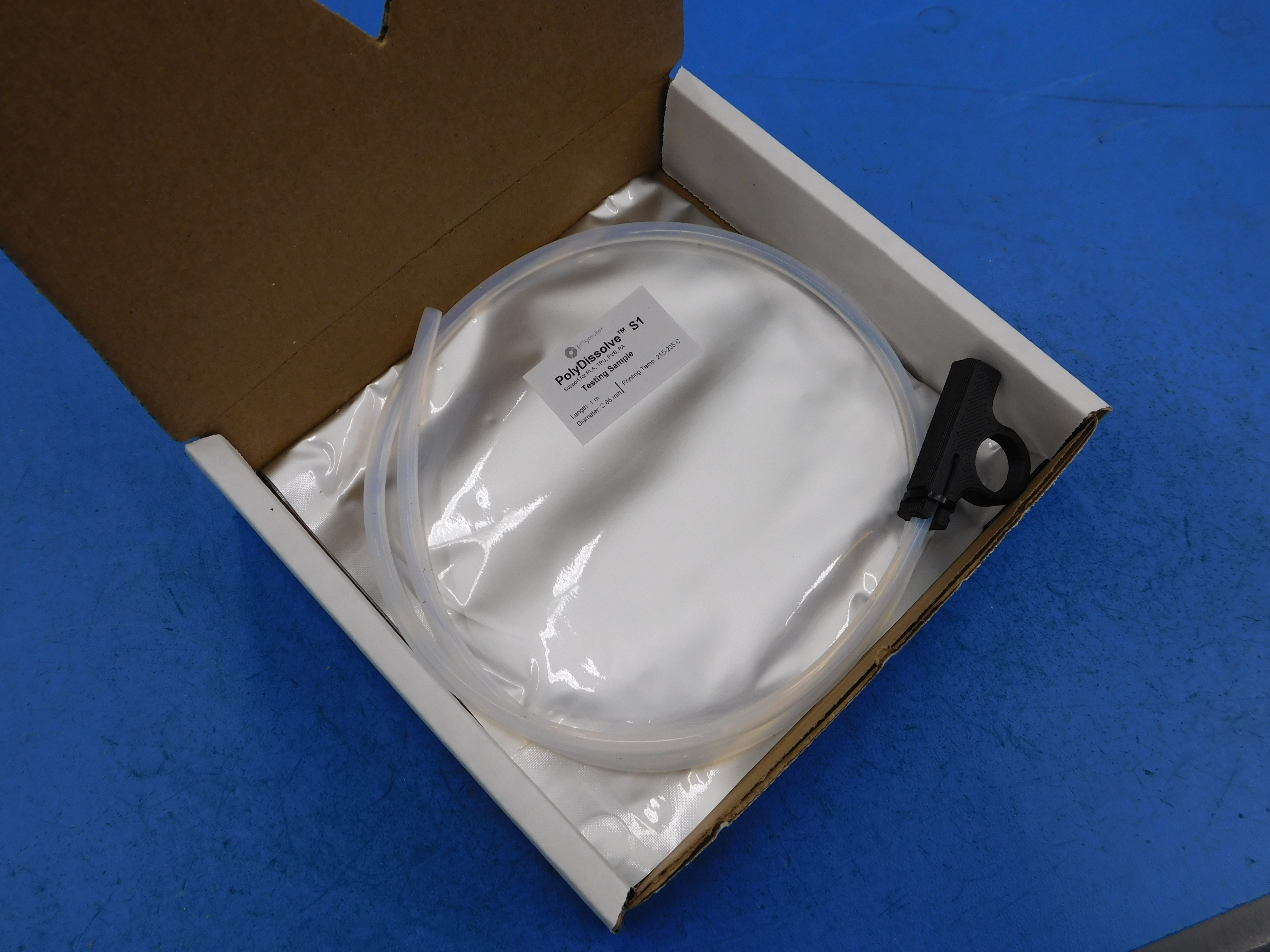
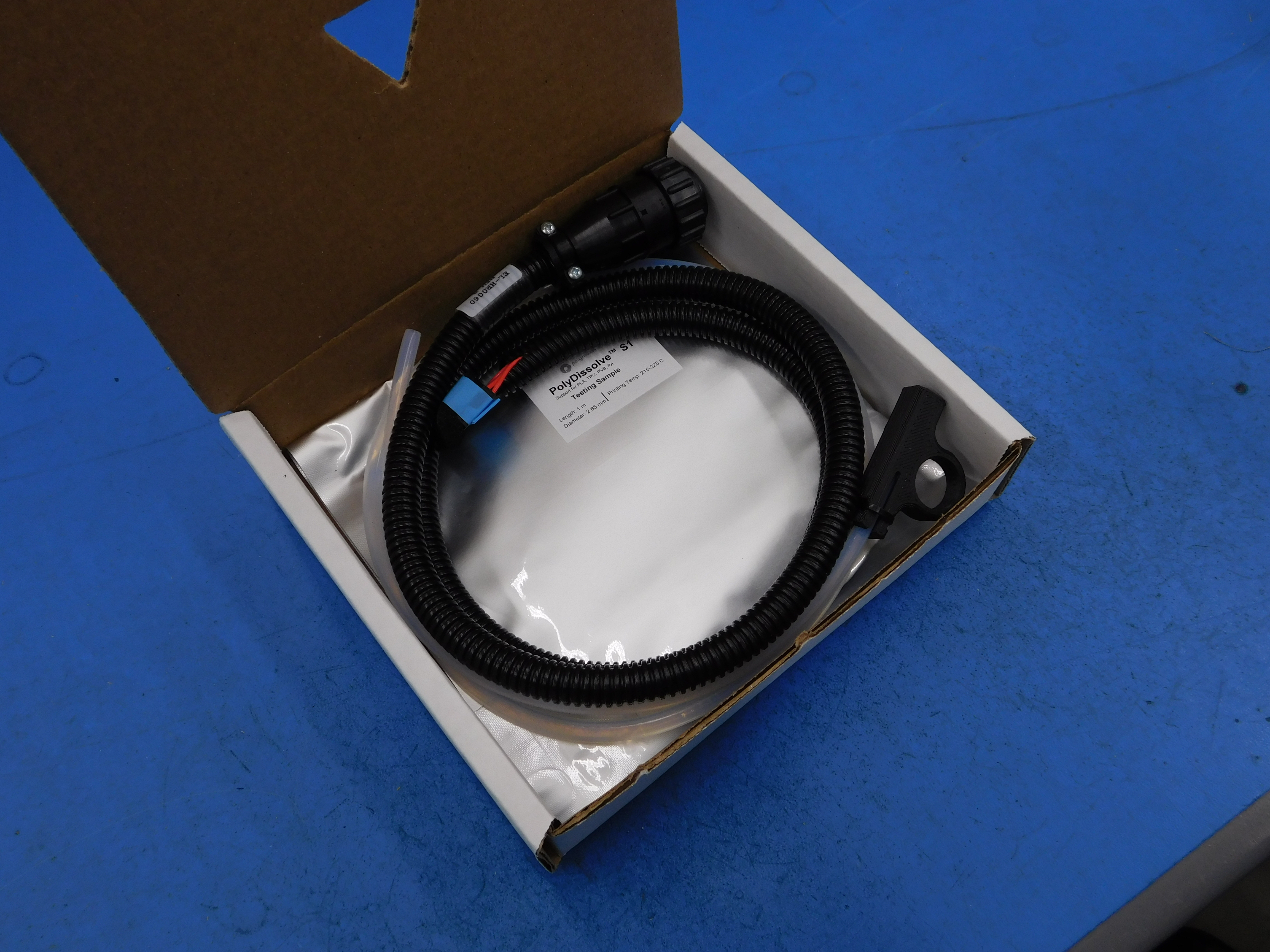
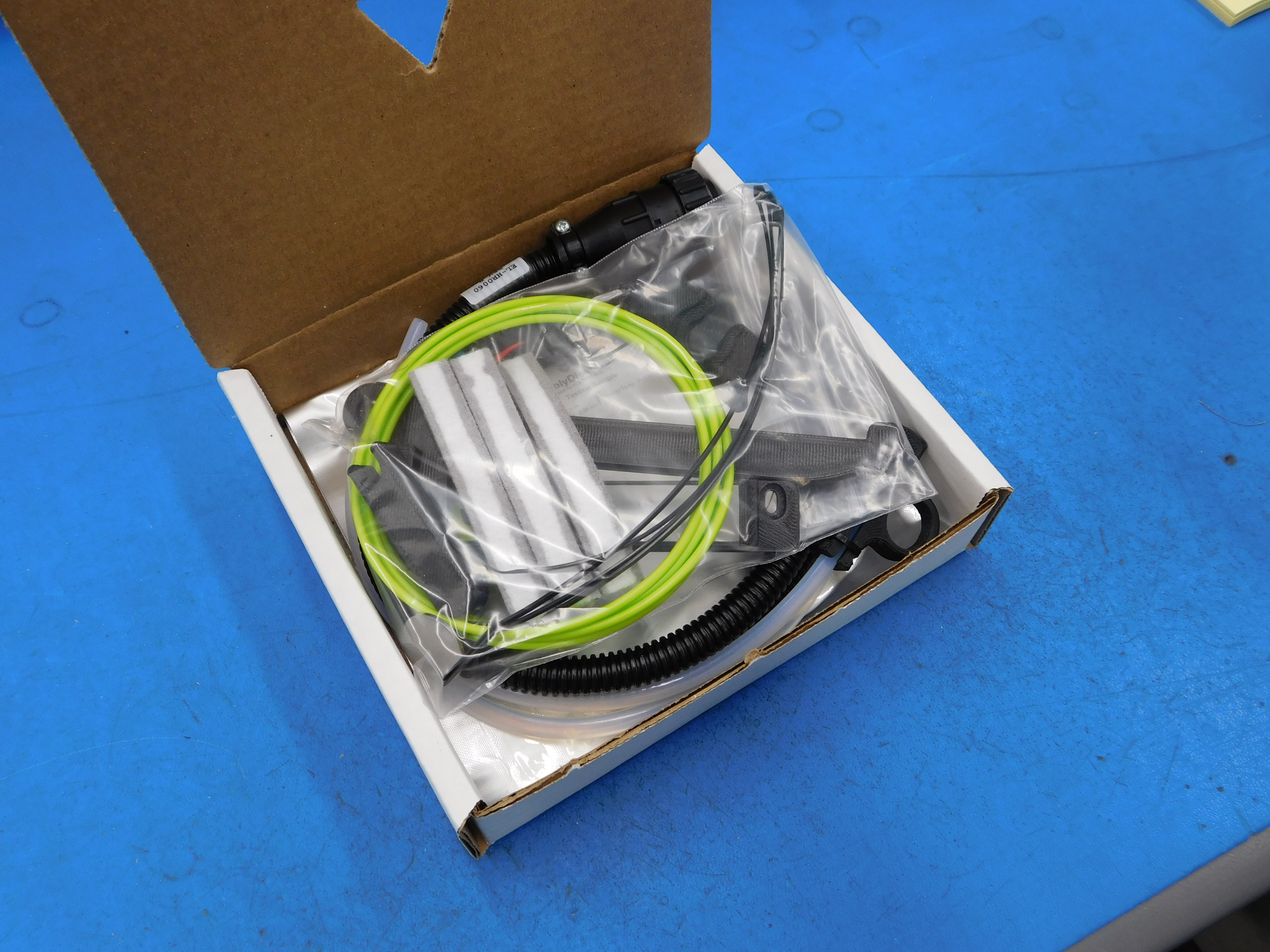
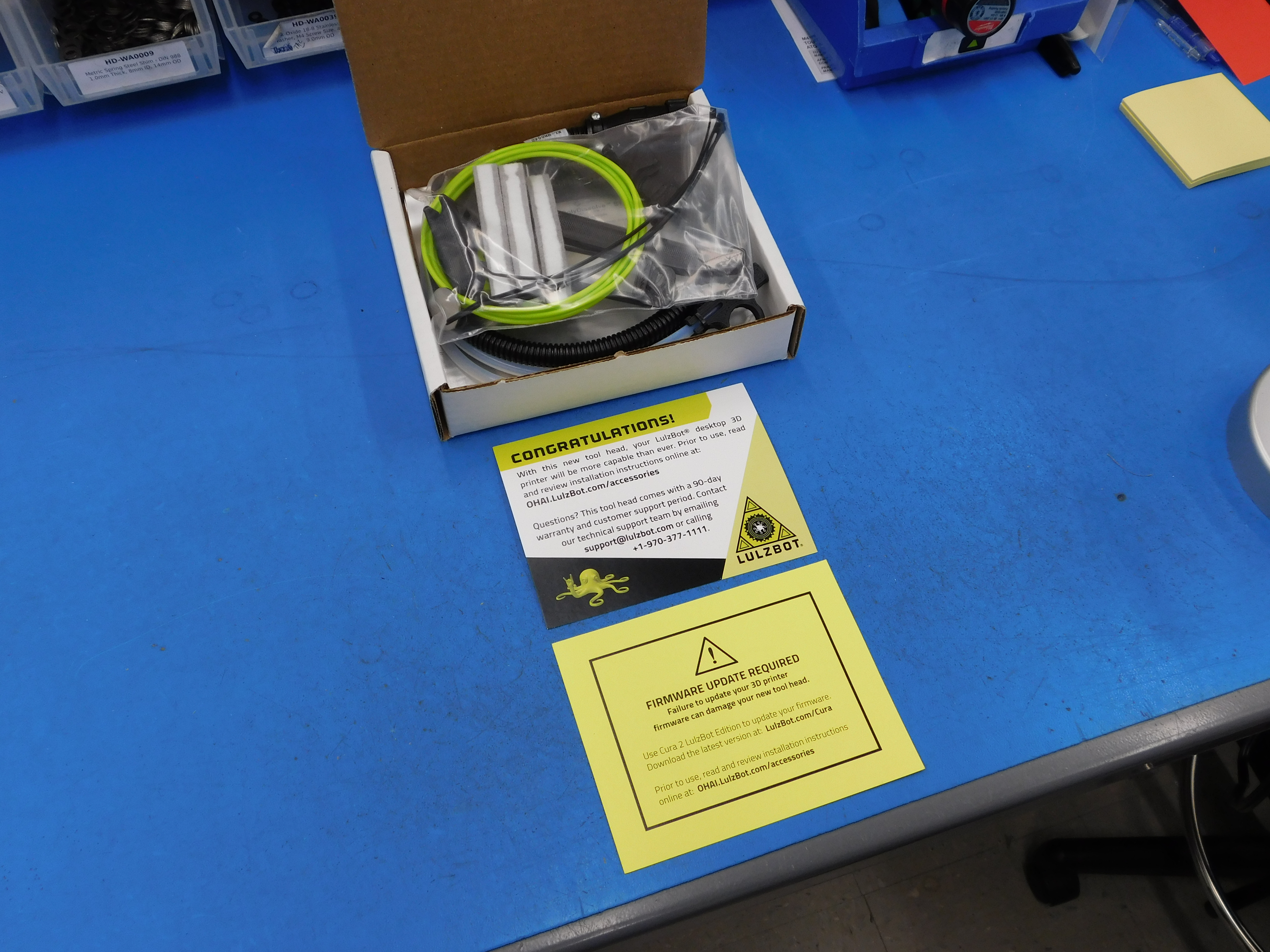
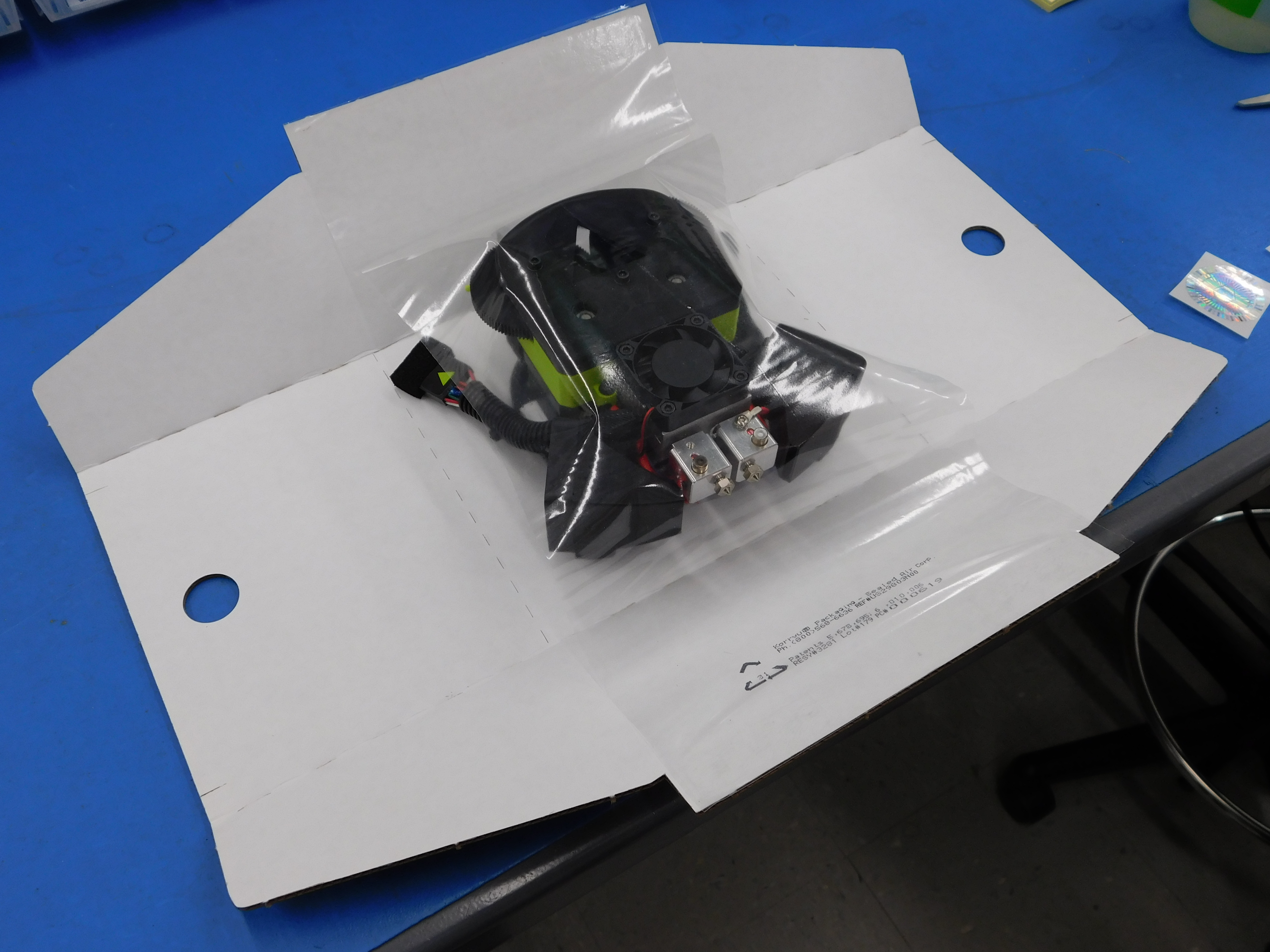
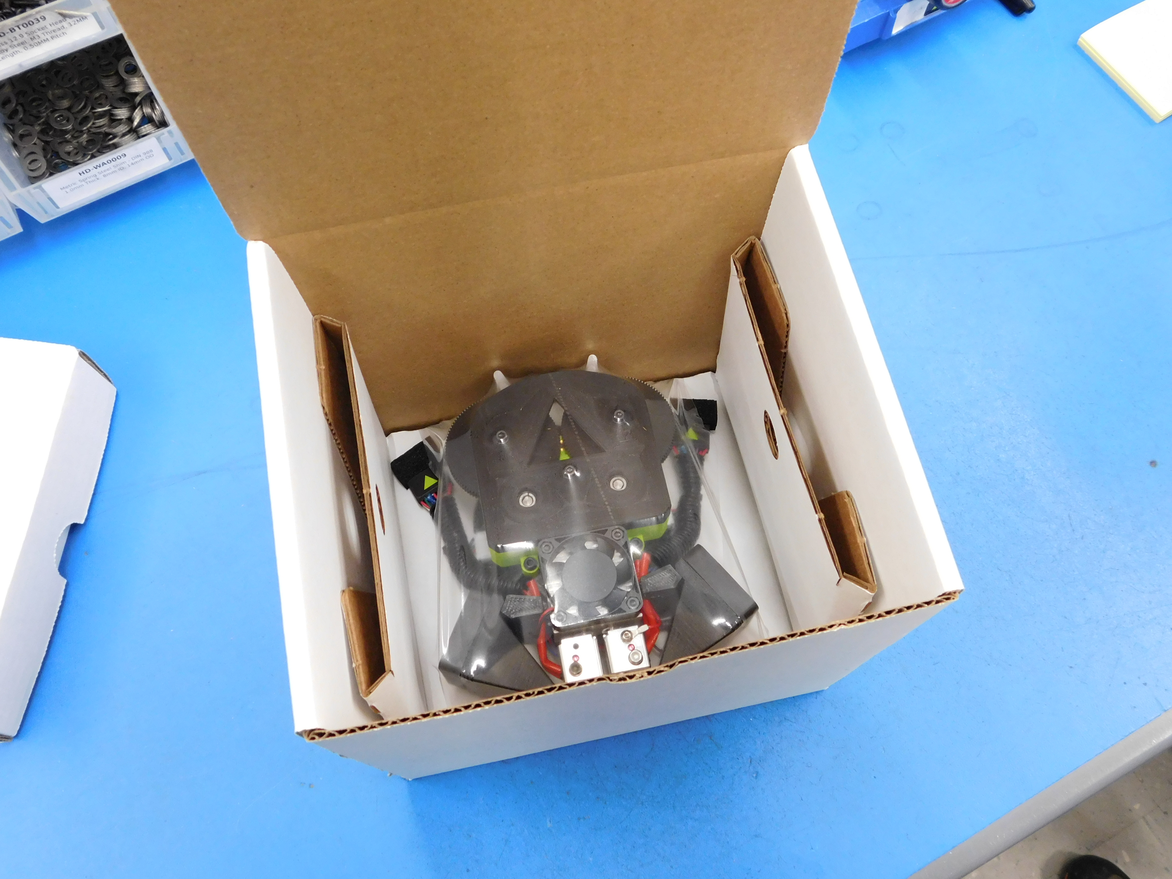
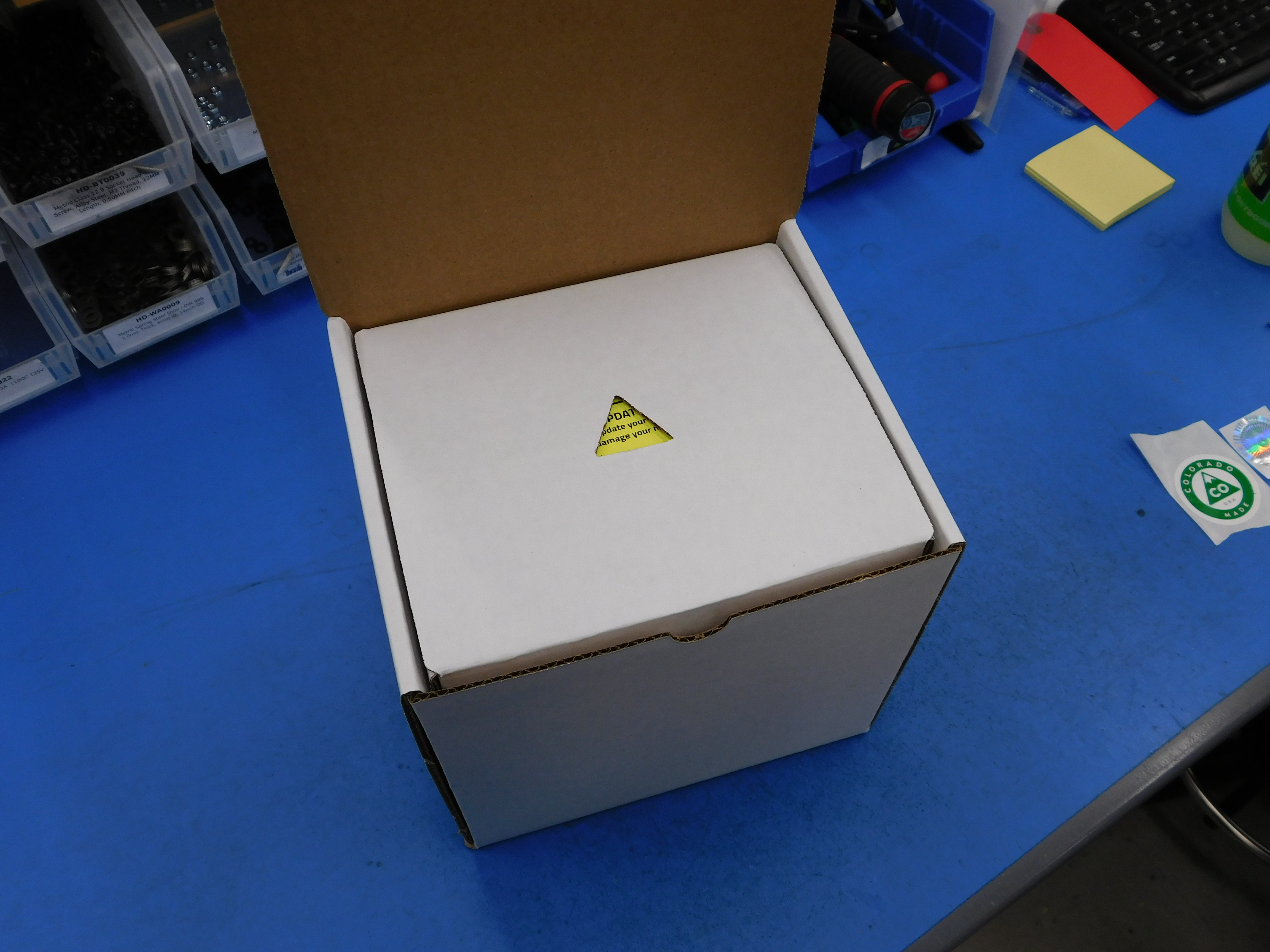
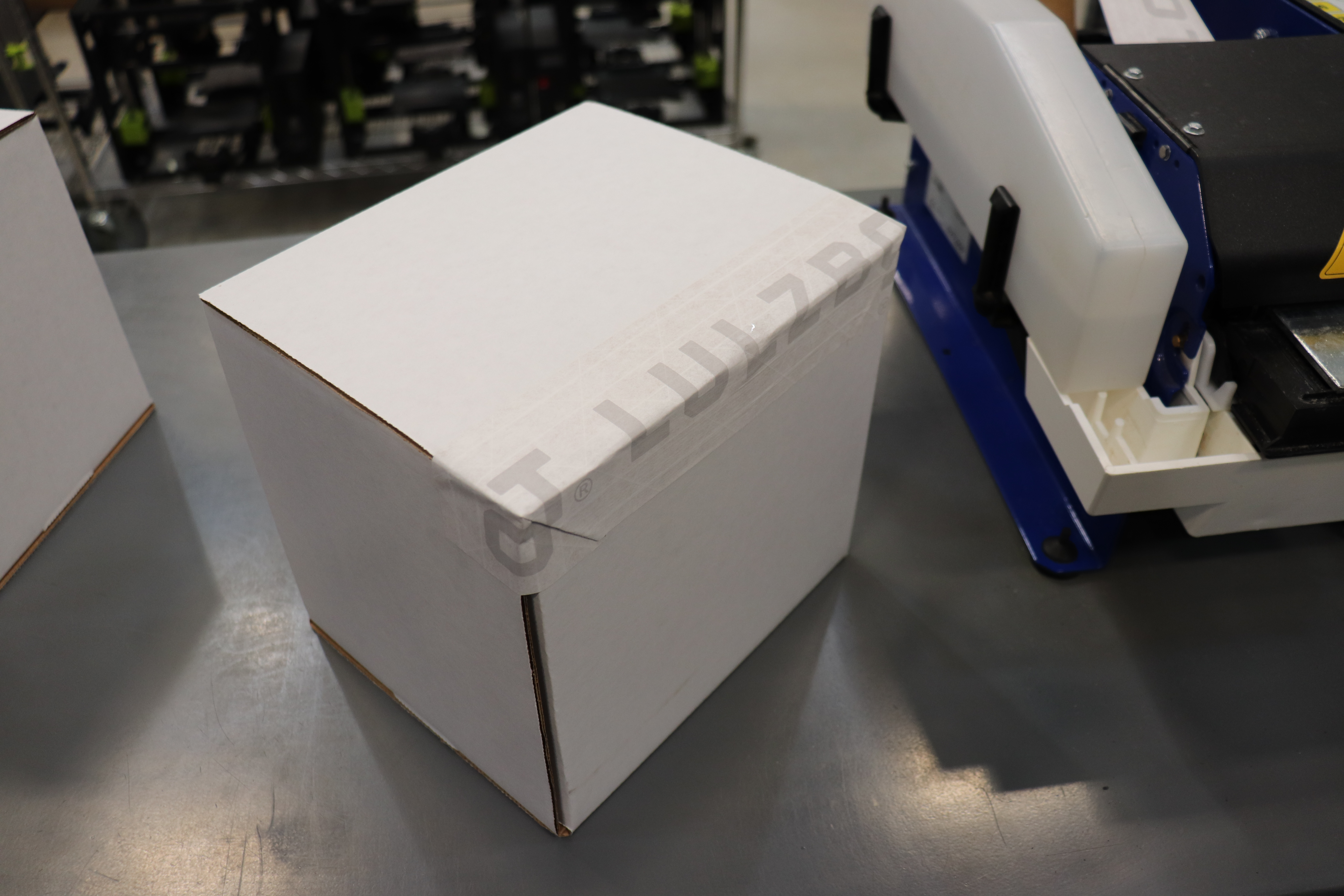
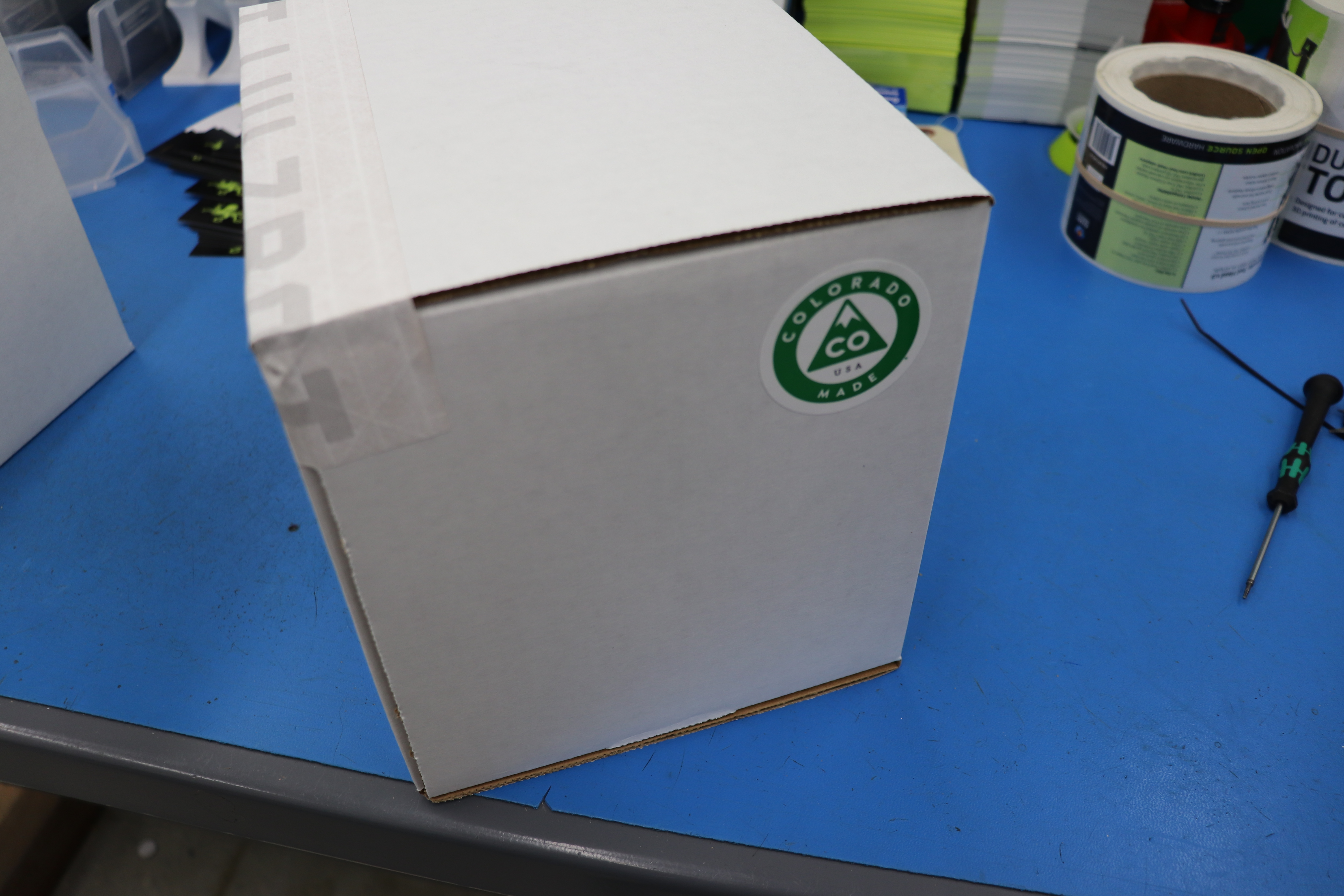
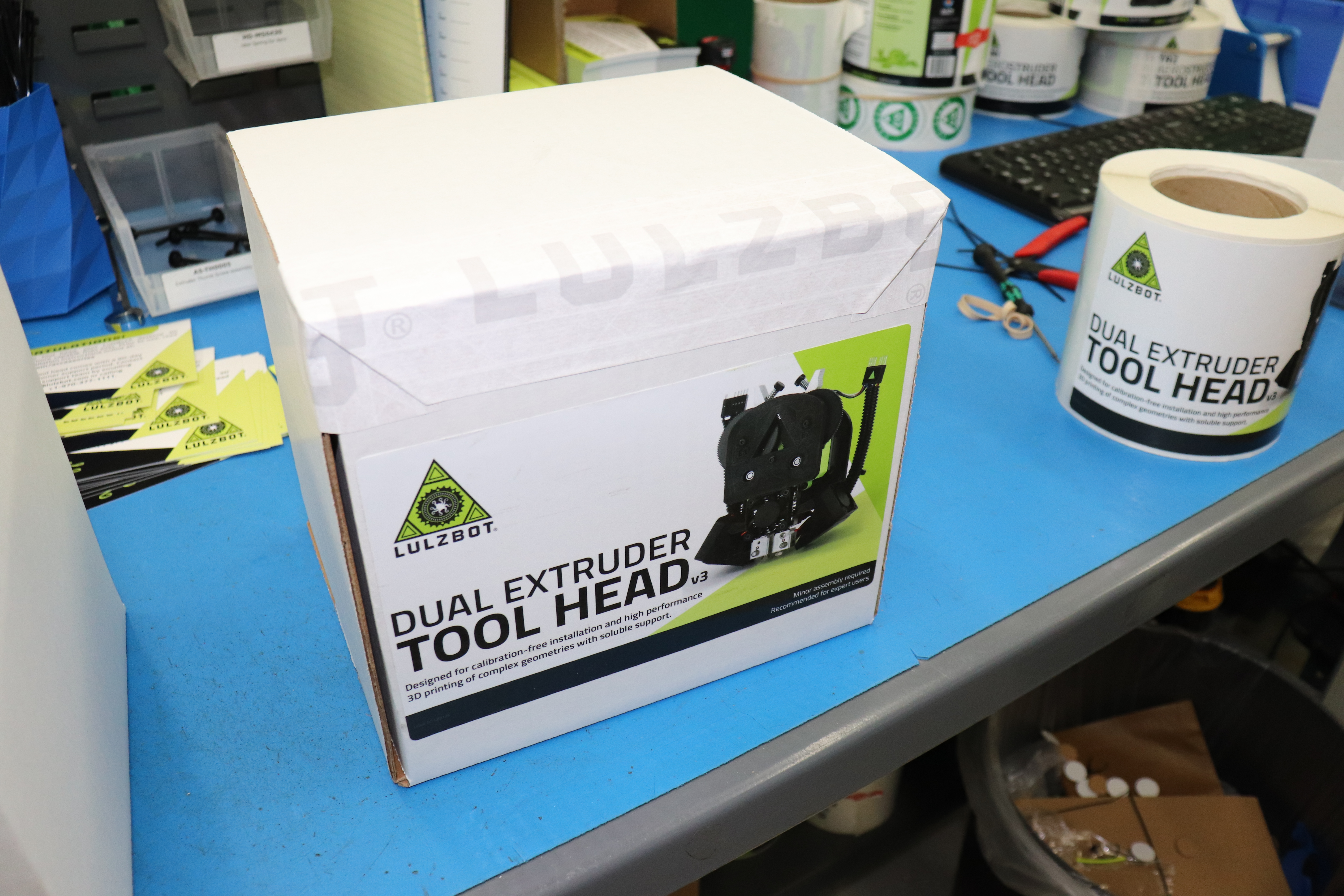
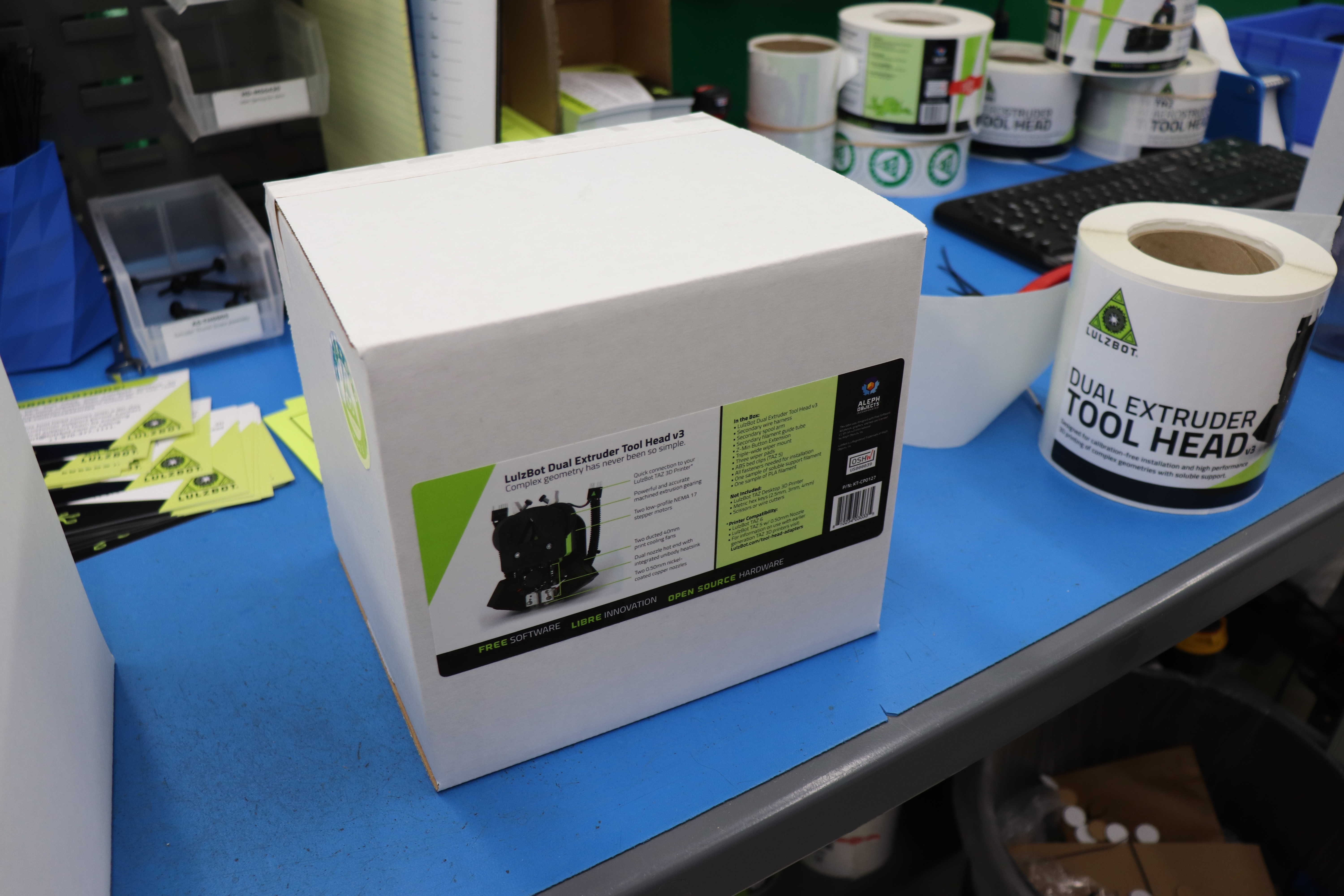
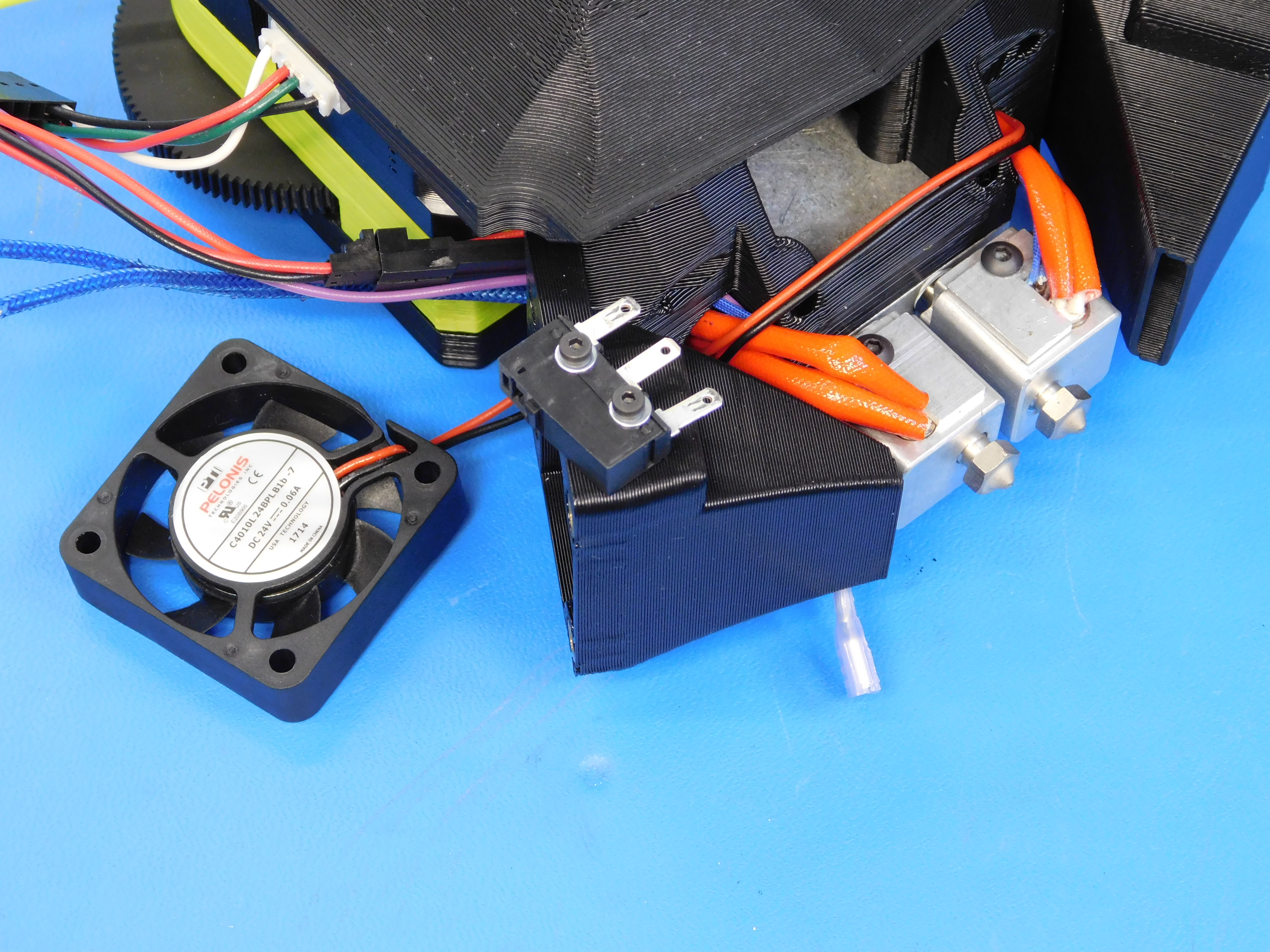
Package the tool head according to the photos.
Parts required:
[AS-TH0056] TAZ Dual V3 Assembly 1.0000 PCE
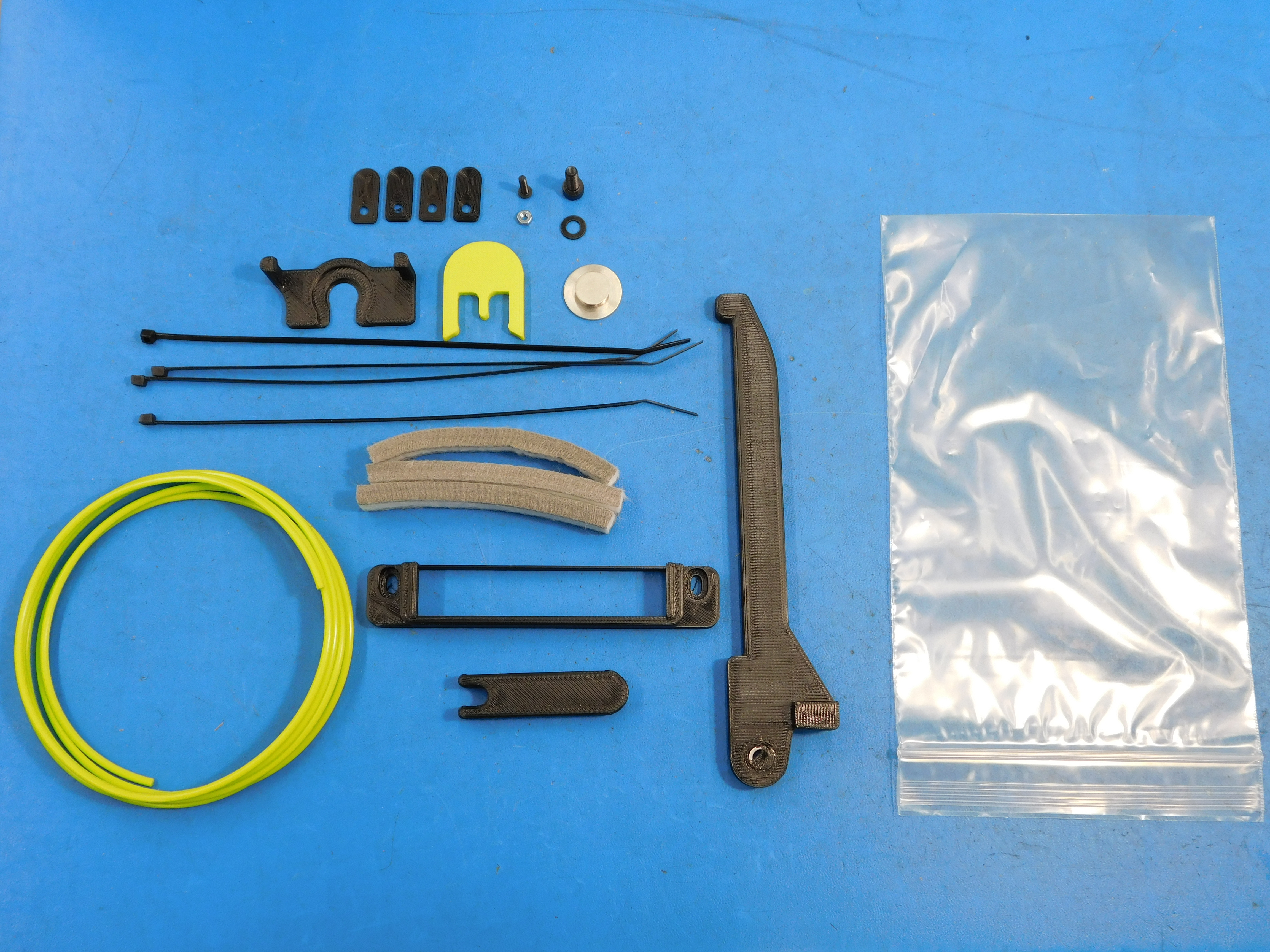
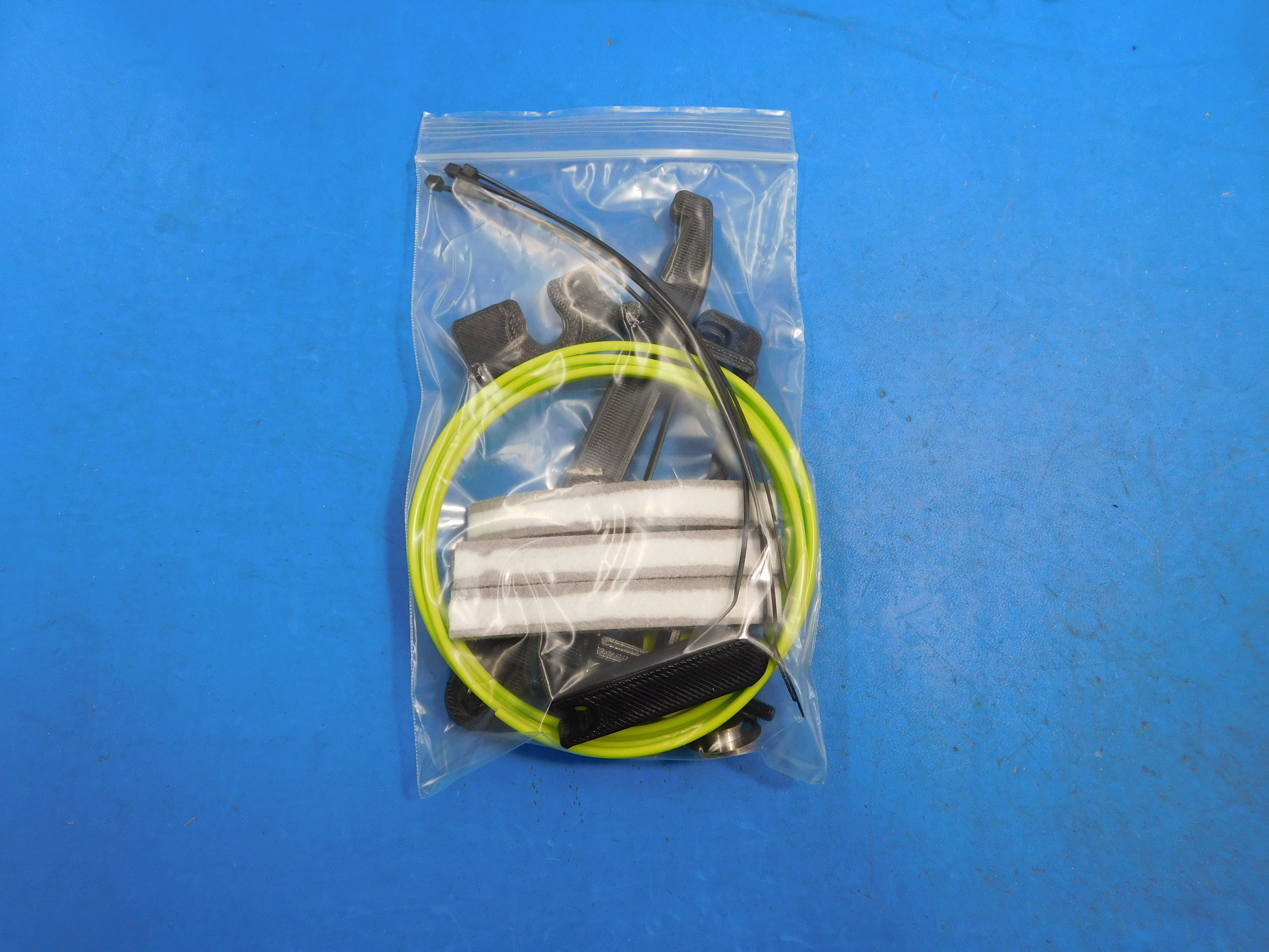
[AS-PK0022] TAZ Dual Extruder V3 Acessories Kit 1.0000 PCE
[AS-PR0082] Feed Tube Assembly, v3.0 1.0000 PCE
[DC-LB0104] Tool Head Wiring Connector Alignment Label 1.0000 PCE
[DC-LB0126] Label, LulzBot TAZ Dual Tool Head V3, 0.5 Nozzle, Front 1.0000 PCE
[DC-LB0132] Label, LulzBot TAZ Dual Tool Head V3, 0.5 Nozzle, Back 1.0000 PCE
[DC-LB0174] P65 Warning Label 1.0000 PCE
[DC-MS0037] Colorado Made Green Sticker 1.0000 PCE
[DC-MS0060] CONGRATULATIONS!- Tool Head Instruction Card 1.0000 PCE
[DC-MS0061] Firmware Update Warning Cards- Cura 2 1.0000 PCE
[EL-HR0060] TAZ Extruder Extension v3.0 1.0000 PCE
[HD-MS0375] ESD Foam 1.06" x .6" x .3" - Extruder Pin Insertion 3.0000 PCE
[RM-PV0009] Polymaker Soulable Support Material Sample, 1 m 1.0000 PCE
[SH-BX0071] Tool Head Outer Carton 7-7/8 x 6-15/16 x 7-11/16 32 ECT B White Die Cut Carton 1.0000 PCE
[SH-BX0072] Tool Head Inner Carton 6-15/16 x 6-9/16 x 1-5/8 32 ECT B White Die Cut Carton 1.0000 PCE
[SH-PA0043] Korrvu US29803N00 Retention Pack (Holds all Print Heads) 1.0000 PCE
[SH-PG0131] White Reinforced Gummed Tape with LulzBot Printed Logo 12 inches
Parts included in accessories kit:
[AS-PR0012] Spool Arm 1.0000 PCE
[AS-PR0023] 90mm wiper pad 3.0000 PCE
[PP-GP0203] T-nut holding jig 1.0000 PCE -
[PP-GP0294] Z min toggle mount 1.0000 PCE
[PP-GP0295] Wiper mount
[PP-GP0298] Low profile bed corner 4.0000 PCE
[PP-GP0306] Tension jig 1.0000 PCE
[HD-BT0049] M5 x 14 SHCS 1.0000 PCE
[HD-BT0146] M3 x 12 BHCS 1.0000 PCE
[HD-MS0058] Wire tie 4.0000 PCE
[HD-NT0004] M3 nut 1.0000 PCE
[HD-NT0044] M5 t-nut 1.0000 PCE
[HD-WA0040] M5 washer 1.0000 PCE
[PP-MP0181] Z min toggle extension 1.0000 PCE
[RM-PL0134] Lulzbot green PLA 280cm
[SH-PG0025] Reclosable bag 1.0000 PCE