Open HardwareAssembly Instructions
Guides for installation and assembly of the LulzBot line of products made by Aleph Objects, Inc.
Guides for installation and assembly of the LulzBot line of products made by Aleph Objects, Inc.
1x- [EL-FA0061] CB Case Fan Assembly
2x- [EL-HR0147] LCD-USB Harness, Assembled
1x- [EL-HR0148] CB Bed Power Harness, Assembled
1x- [EL-HR0152] CB PSU to Ground Green Harness, Assembled
1x- [EL-HR0154] DC Power Harness, Assembled
1x- [EL-HR0157] CB Switch to PSU Harness, Assembled
1x- [EL-HR0167] Plug to ground green
1x- [EL-HR0168] Plug to switch black and white with ferrite
1x- [EL-HR0173] CB X Harness
1x- [EL-HR0174] Bed Power Harness
1x- [EL-HR0175] CB Extruder Harness
1x- [EL-HR0176] CB Dual Extruder Harness
1x- [EL-HR0177] CB Y End-Stop Harness
1x- [EL-HR0179] X Harness
1x- [EL-HR0180] Y Bed Harness
1x- [EL-HR0181] YZ End Harness
1x- [EL-HR0183] CB YZ Harness
1x- [EL-HR0184] CB Bed Harness
1x- [EL-HR0185] CB Z Endstop Harness
1x- [PC-BD0094] RAMBo Electronics v1.4L Assembled Board Only
1x- [PP-FP0153] TAZ Interconnect Cover, Quiver
1x- [PP-FP0163] TAZ Workhorse, TAZ6 Electronics Chassis w/ Workhorse Graphics
1x- [PP-FP0164] TAZ Workhorse, TAZ6 Electronics Chassis Cover w/ Workhorse Graphics
1x- [EL-MS0346] MOD PWR ENTRY INLET W/FUSE Receptacle
1x- [EL-MS0347] Fuse Ceramic 6.3A 250VAC 5X20MM
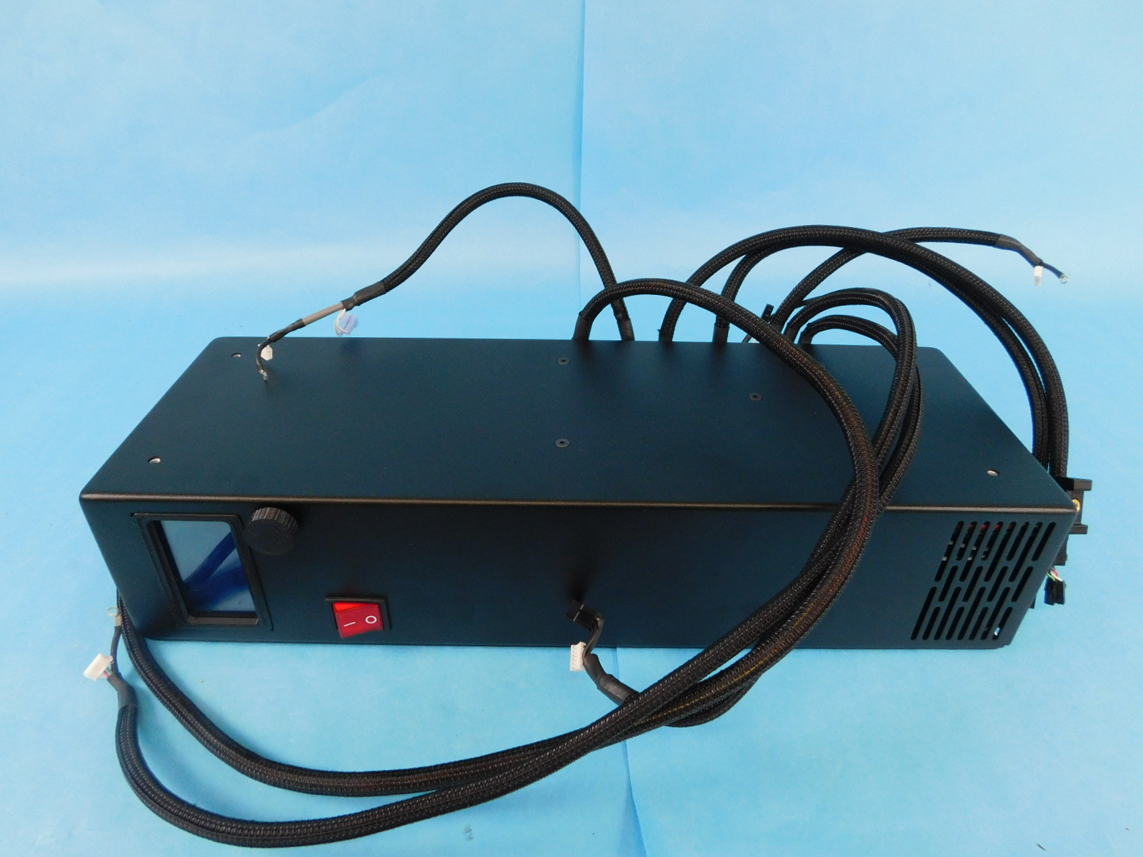
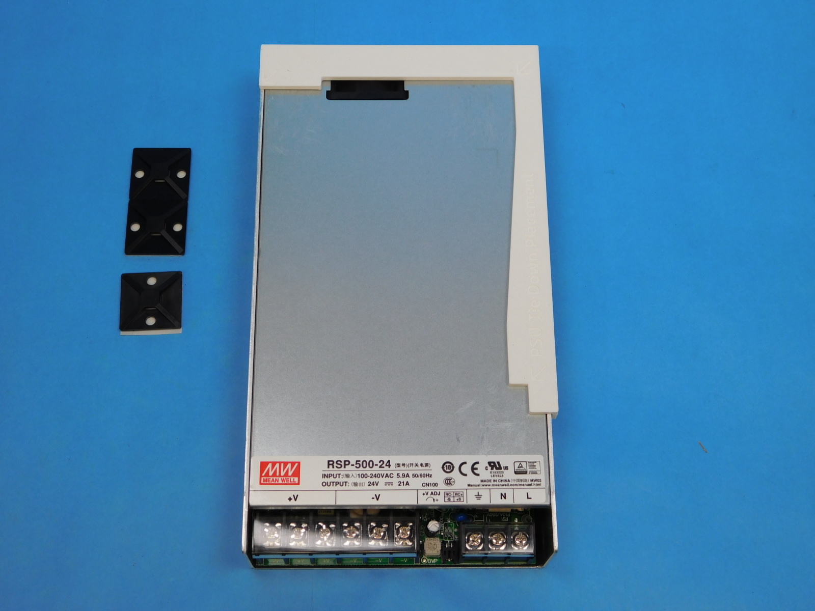
1x- [EL-PS0031] AC-DC POWER SUPPLY, Enclosed with Fan, 500 W, Single Output, 24 V@21 A
1x- [EL-SW0023] SWITCH ROCKER DPST 20A 250V, Illuminated Red
1x- [PC-AS0041] Plastic Laser Cut LCD Cover
1x- [PC-AS0056] LCD LB_GLCD
4x- [PP-GP0089] LCD_spacer_v0.4
1x- [PP-GP0230] LCD_bezel
1x- [PP-GP0235] SD card bezel v0.8
1x- [PP-GP0438] Interconnect Housing, Black, Workhorse
1x- [PP-IS0116] Y-Cable Mount with Insert
1x- [AS-PR0169] 5A Fuse Mount Sub-Assembly
4x- [HD-BT0053] Flat Head Phillips Machine Screw, Black-Oxide, 4-40 Thread, 1/4" Length
4x- [HD-BT0054] M2.5x12 SHCS, Black-Oxide
4x- [HD-BT0104] M3x8 BHCS, Stainless Steel
2x- [HD-BT0116] M3x10 FHCS, Black-Oxide
5x- [HD-BT0137] M3x8 BHCS, Black-Oxide
10x- [HD-BT0140] M3x6 BHCS Black-Oxide
4x- [HD-BT0171] M3x20 BHCS, Black-Oxide
5x- [HD-BT0155] M4x6 FHCS, Black-Oxide
1x- [HD-BT0234] M3x10 BHCS Stainless Steel
9x- [HD-MS0058] Wire Tie, 8" Black
6x- [HD-MS0249] UV-Resistant Cable Tie Holder, Adhesive Back
6x- [HD-NT0001] M3 Nyloc Nut
4x- [HD-WA0013] M2.5 Washer
3x- [HD-WA0035] M3 Stainless Steel External Serrated Lock Washer
19x- [HD-WA0038] M3 Washer, Black-Oxide
10mm - [EL-MS0560] Conductive Copper Foil Electrical Tape Conductive Adhesive, 3/4" Wide
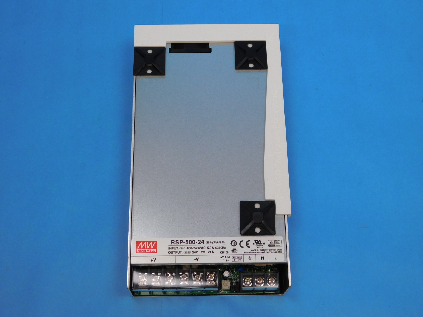
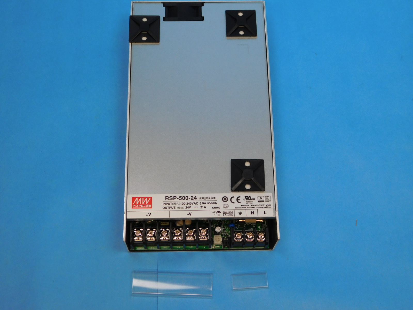
Using the printed alignment jig, position 3x- [HD-MS0249] on the top surface of the Power Supply [EL-PS0031] at each arrow, as pictured.
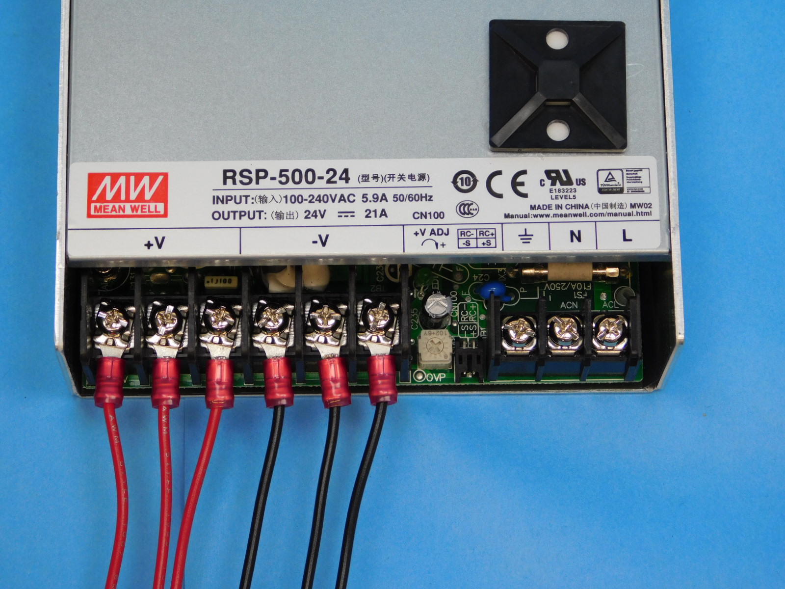
Remove both of the clear terminal shields to gain access to all 9 screw terminals.
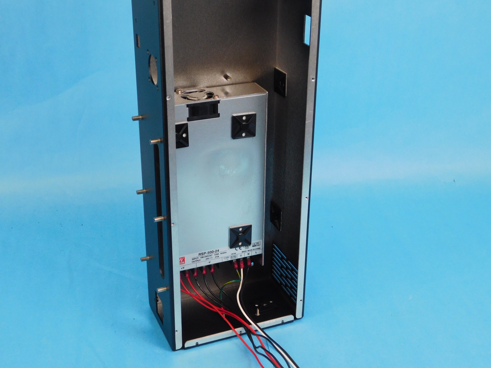
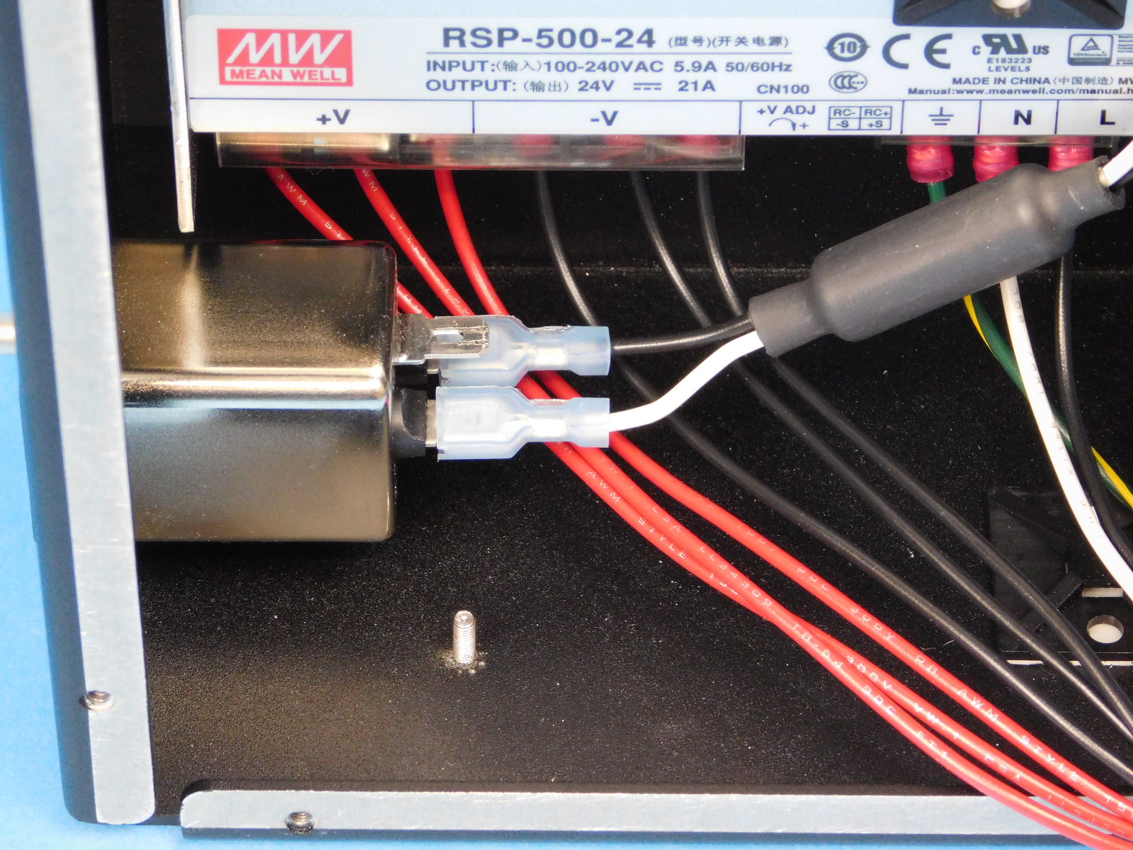
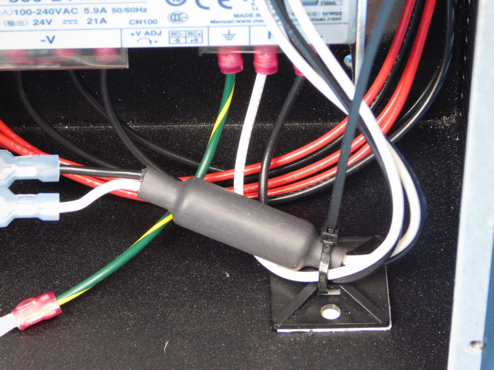
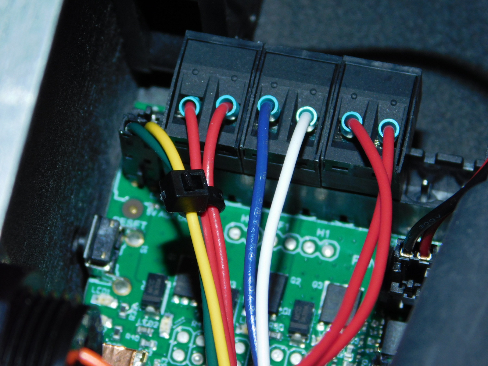
Connect [EL-HR0154] CB DC Power Harness to the power supply;
Using a P2 Phillips Screwdriver (or equivalent bit for power driver) loosen the screw terminals until the fork terminals can be inserted, (3 red (+3) and 3 black (-3)) to power supply.
Secure screws to finger tight then ¼ turn past.
Ensure the black leads are connected to the terminals marked “-V” and the red leads are connected to the terminals marked “+V”.
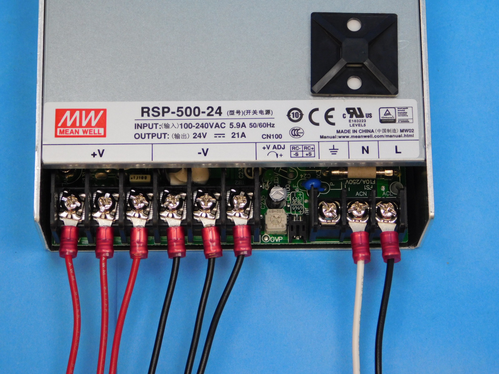
Connect [EL-HR0157] CB Switch to PSU Harness;
Secure the black lead in the terminal labeled “L”
Secure the white lead in the terminal labeled “N”
Secure screws to finger tight then a ¼ past.
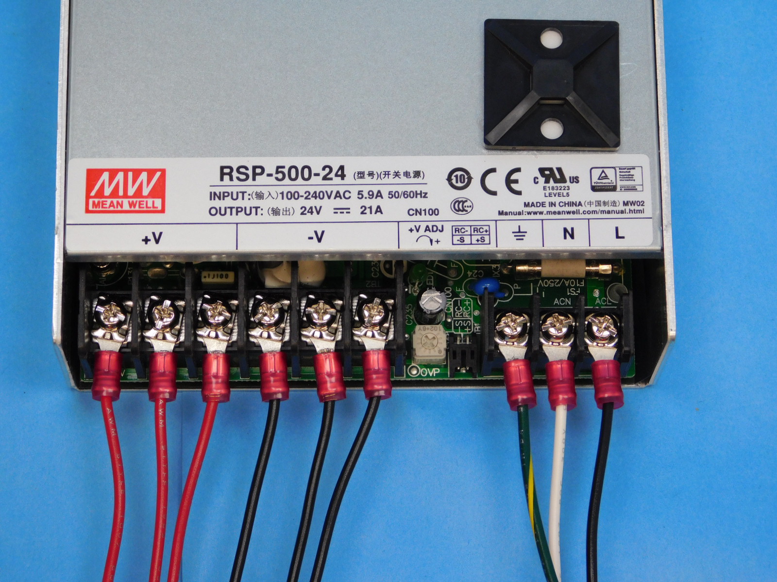
Connect [EL-HR0152] PSU to Ground Green to power supply ground terminal.
Secure screws to finger tight then a ¼ past.
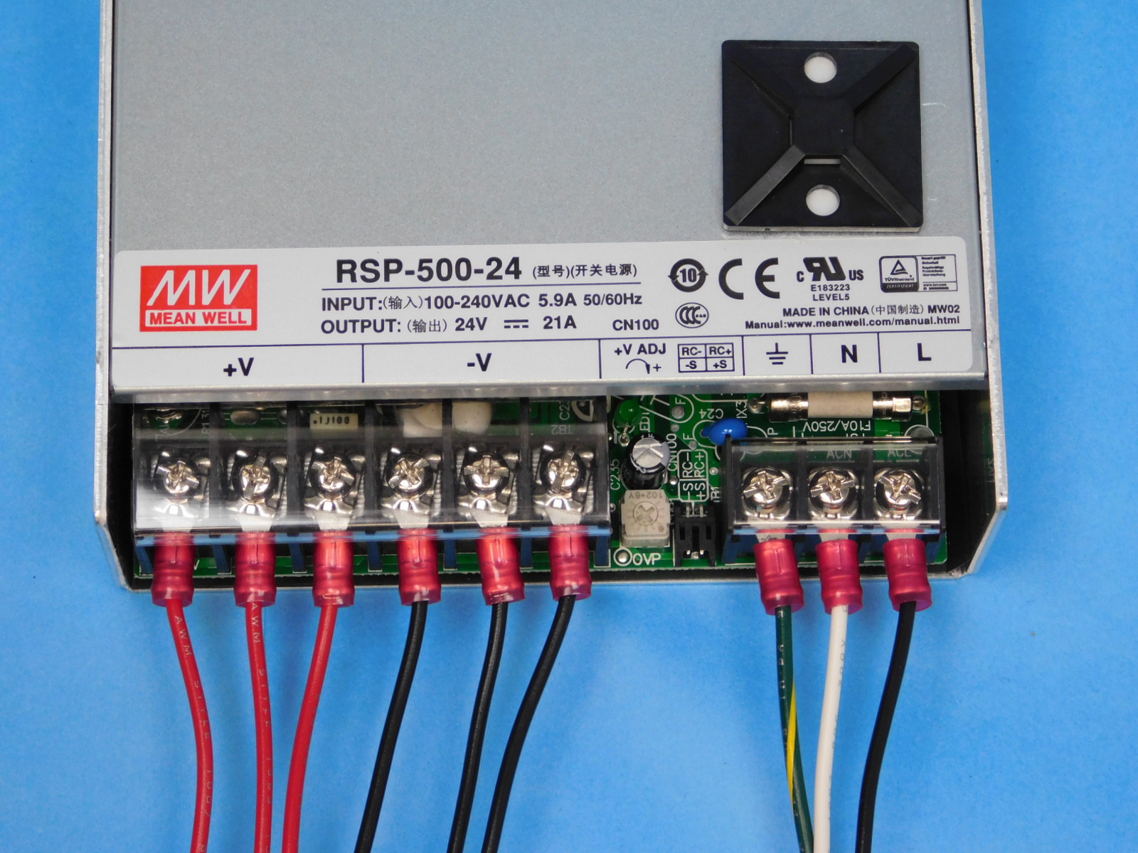
Replace the two clear terminal shields to their original location.
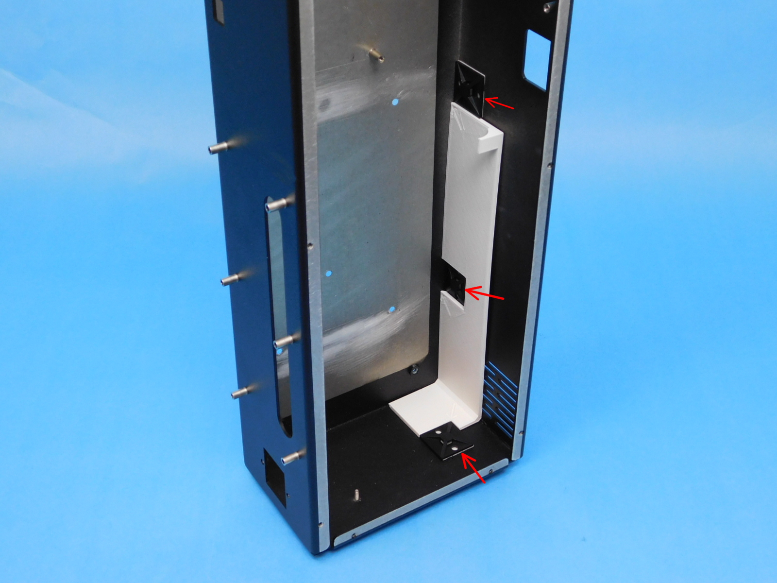
Using the printed alignment jig, position 3x- [HD-MS0249] inside the Electronics Chassis [PP-FP0163], one on the bottom of the case, and two along the inner front edge, as pictured.
Place the prepared power supply from the previous step on the stand jig as pictured, carefully place the Electronics Chassis [PP-FP0163] over the power supply with the bottom facing you, line up the fastener holes of the case with the fastener holes of the power supply.
Secure using 5x- [HD-BT0155] M4x6 FHCS, torque to 5in*lbs
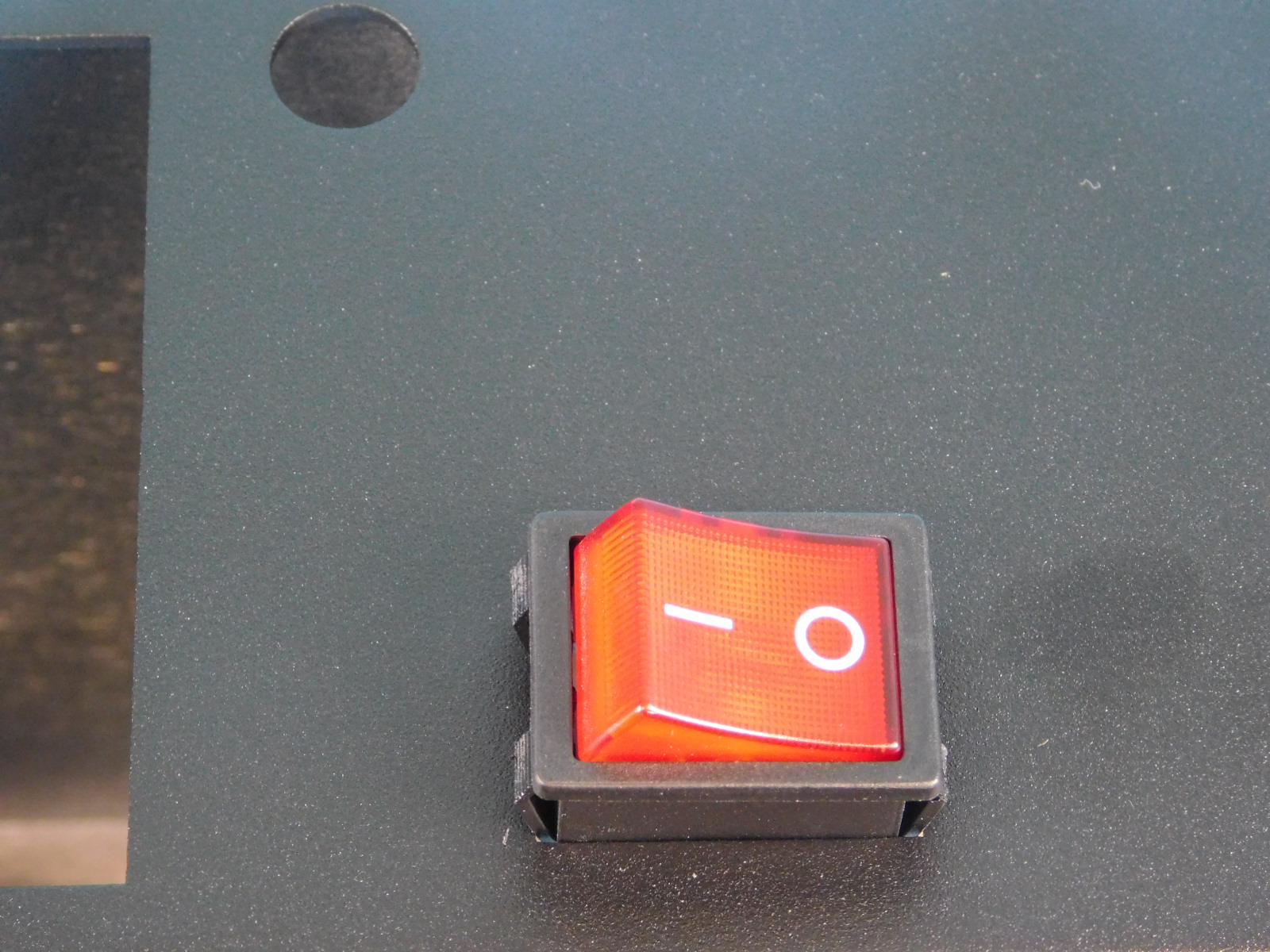
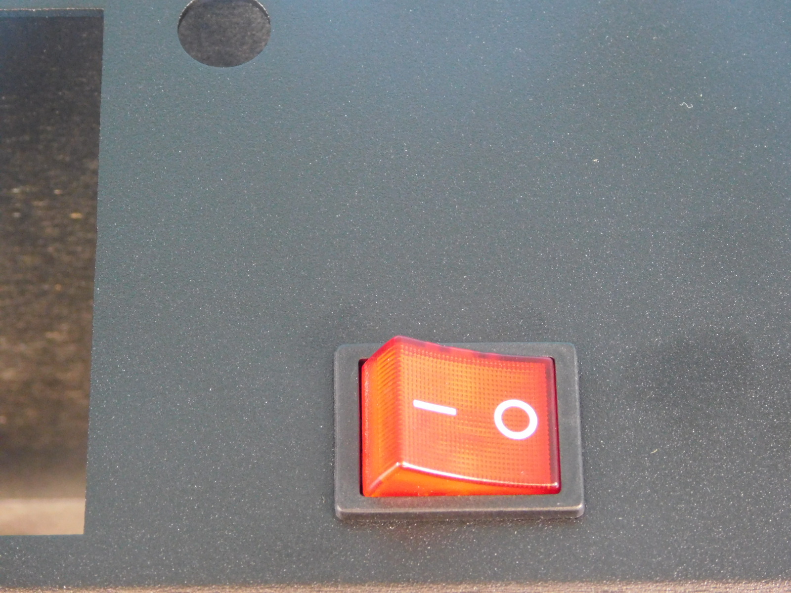
Install one Power Switch [EL-SW0023] into the slot on the front of the chassis [PP-FP0163] with the “I” facing the “ON” label on the chassis. The rocker switch will press in from the front of the case and be held by the clips on the top and bottom of the switch.
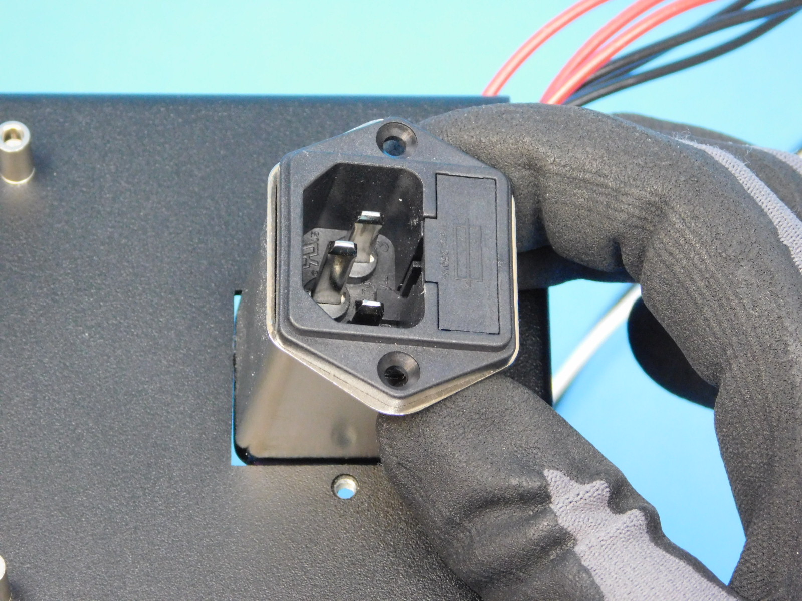
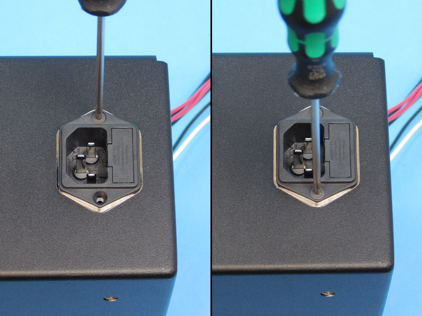
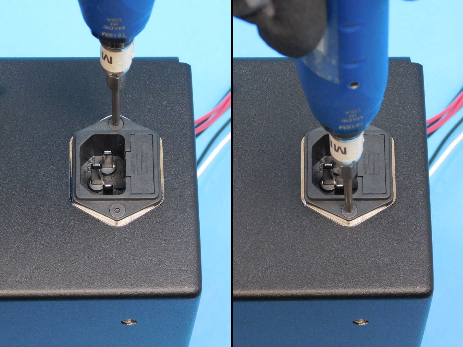
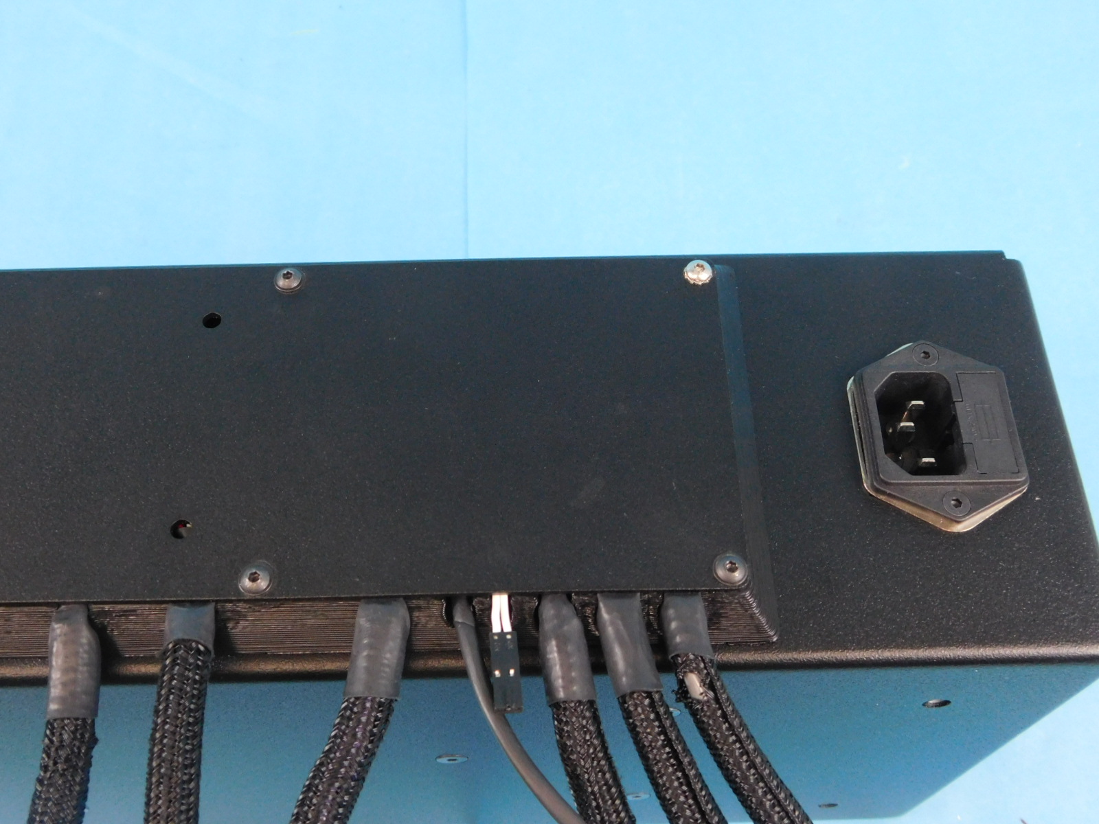
Install one receptacle [EL-MS0346] into the hole at the bottom rear of the chassis [PP-FP0163] with the plug side of the receptacle facing the top of the chassis.
Secure using two M3x10 FHCS [HD-BT0116], torque to 5in-lbs
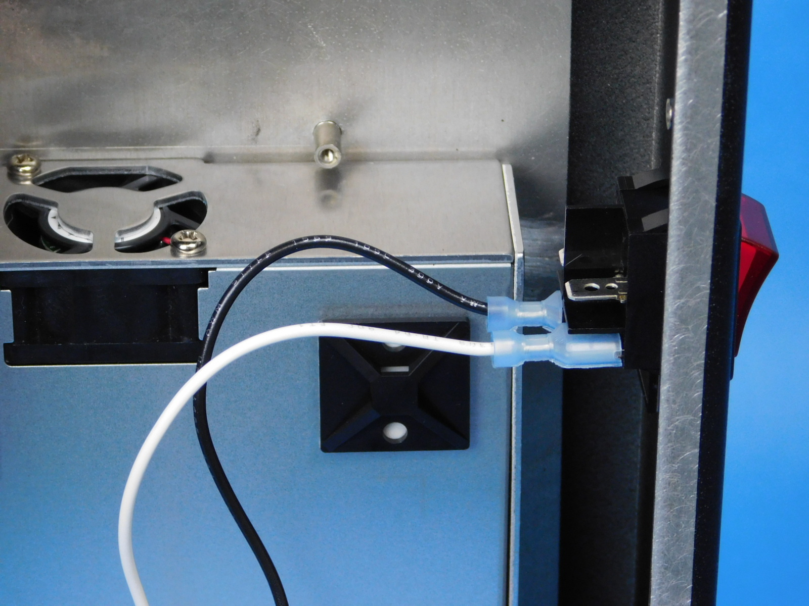
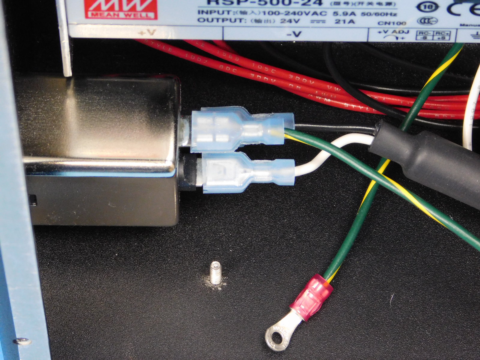
Obtain one Plug to Switch Harness [EL-HR0168]
Connect the ferrite end of the harness to the bottom two prongs of the receptacle with the black lead on the prong closest the inside of the case, and the white lead on the prong closest the outside of the case.
Connect the other end of the harness to the bottom two terminals of the switch with the black lead on the prong closest the inside of the case, and the white lead on the prong closest the outside of the case.
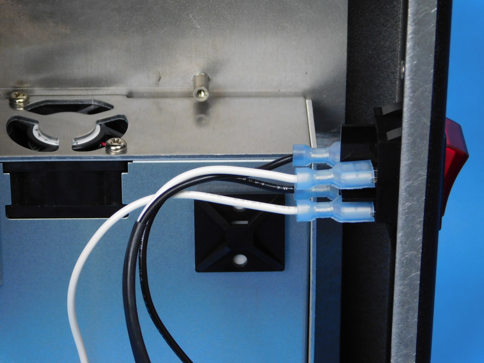
Connect the white and black leads from the power supply [EL-HR0157] to the two terminals on the top of the switch similarly; with the black lead on the prong closest the inside of the case, and the white lead on the prong closest the outside of the case.
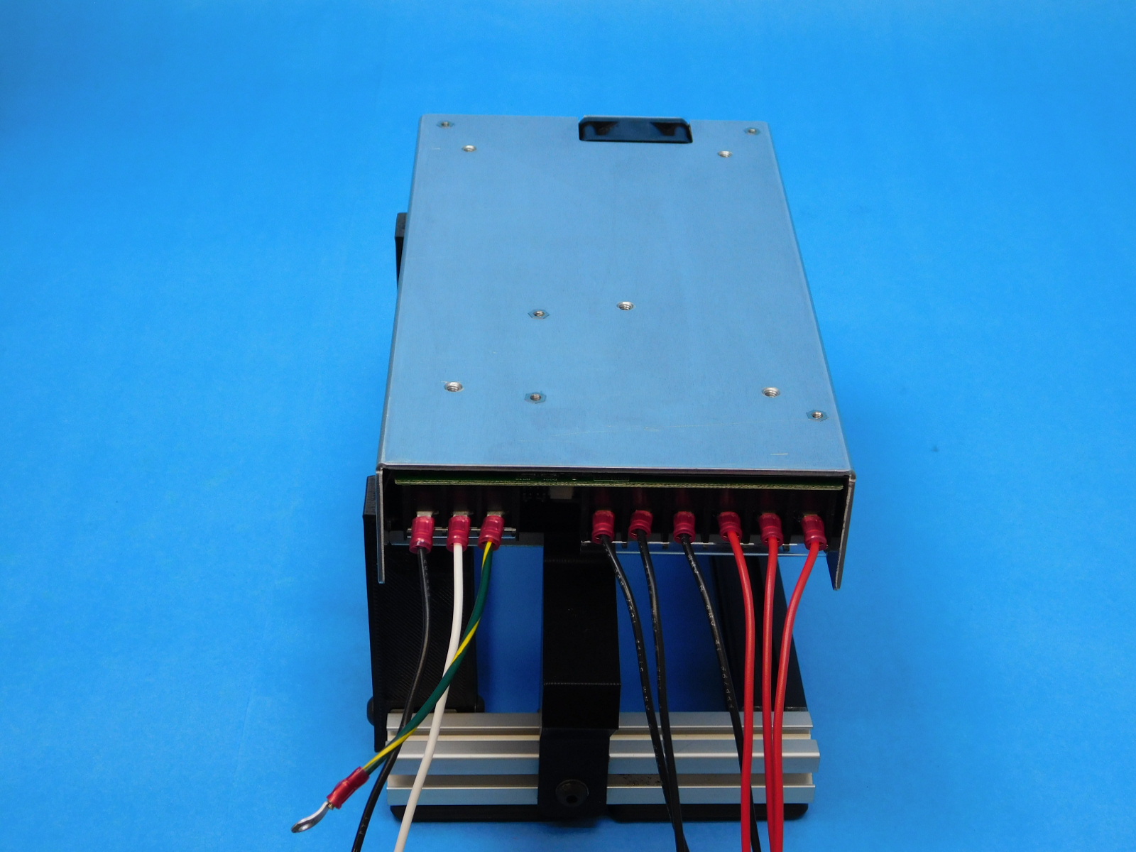
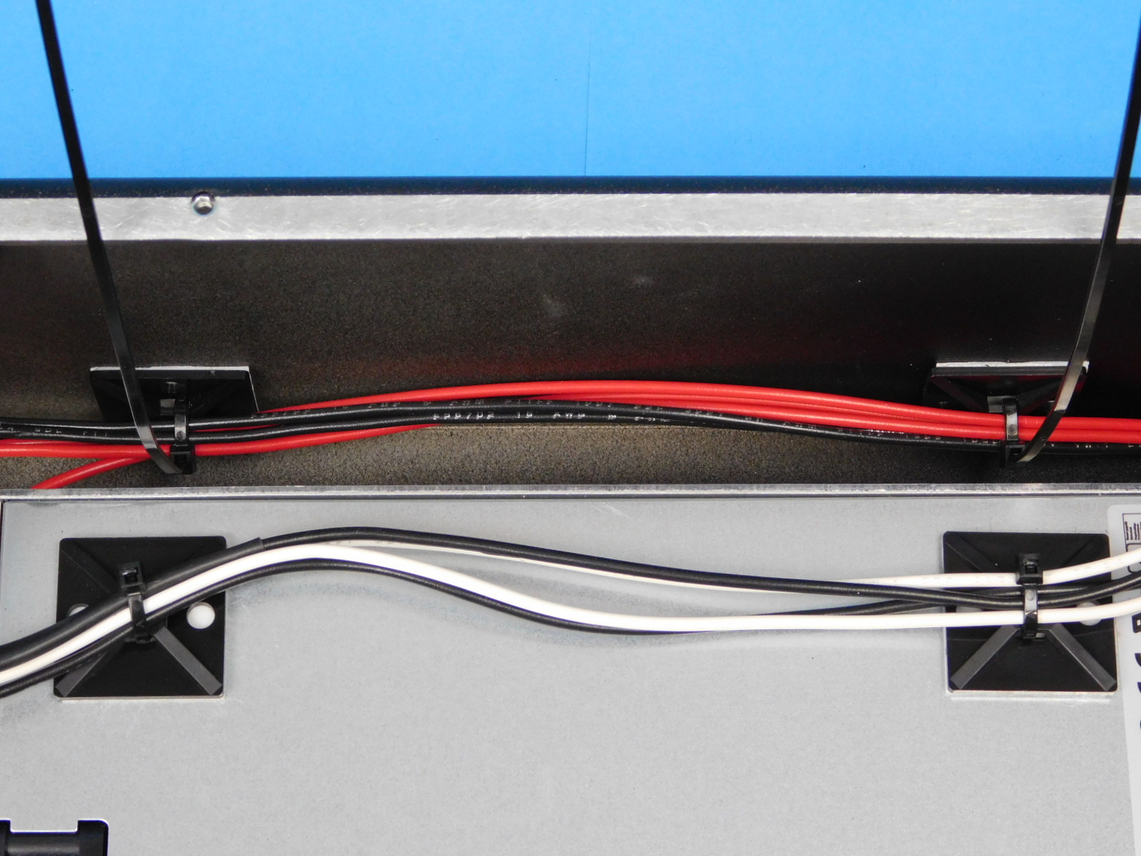
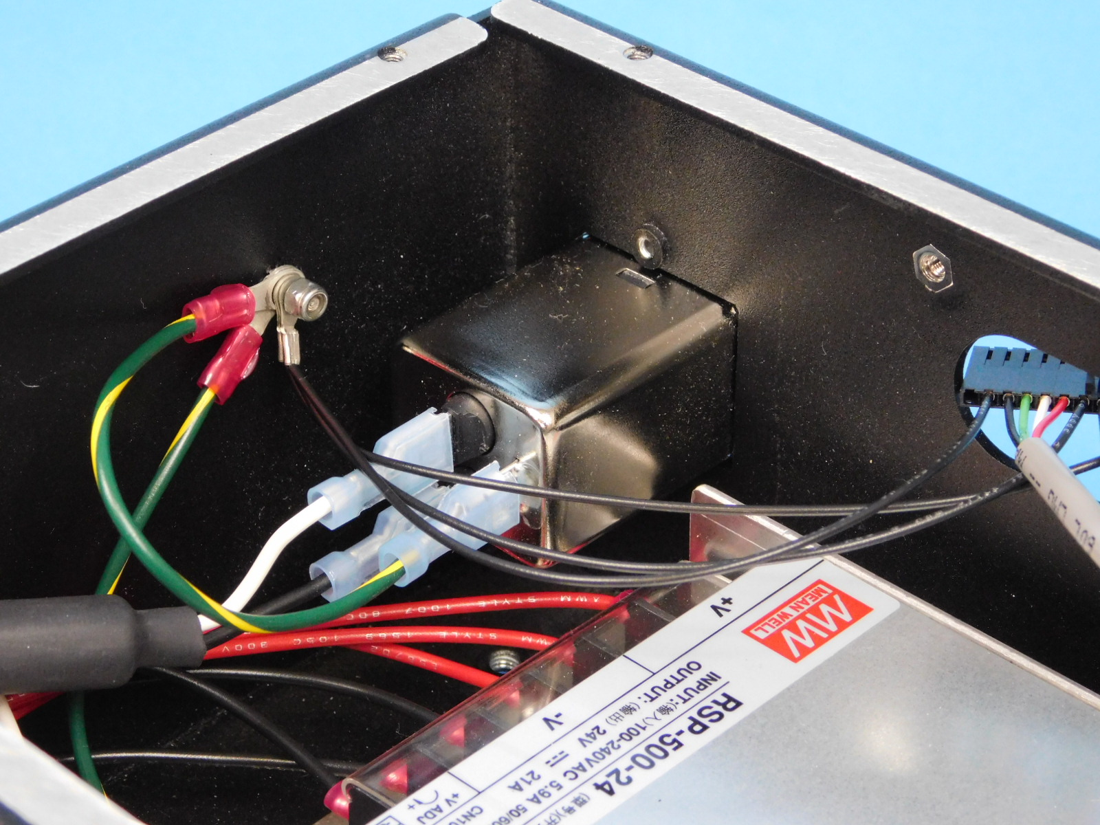
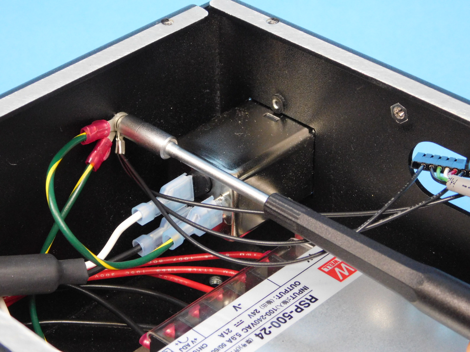
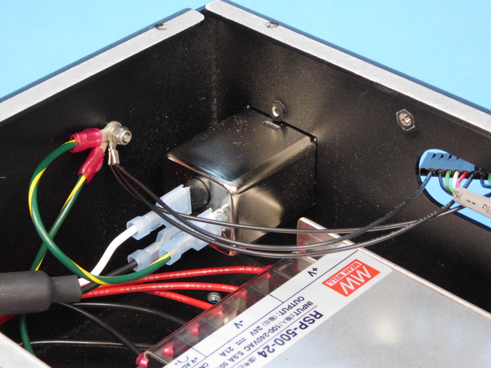
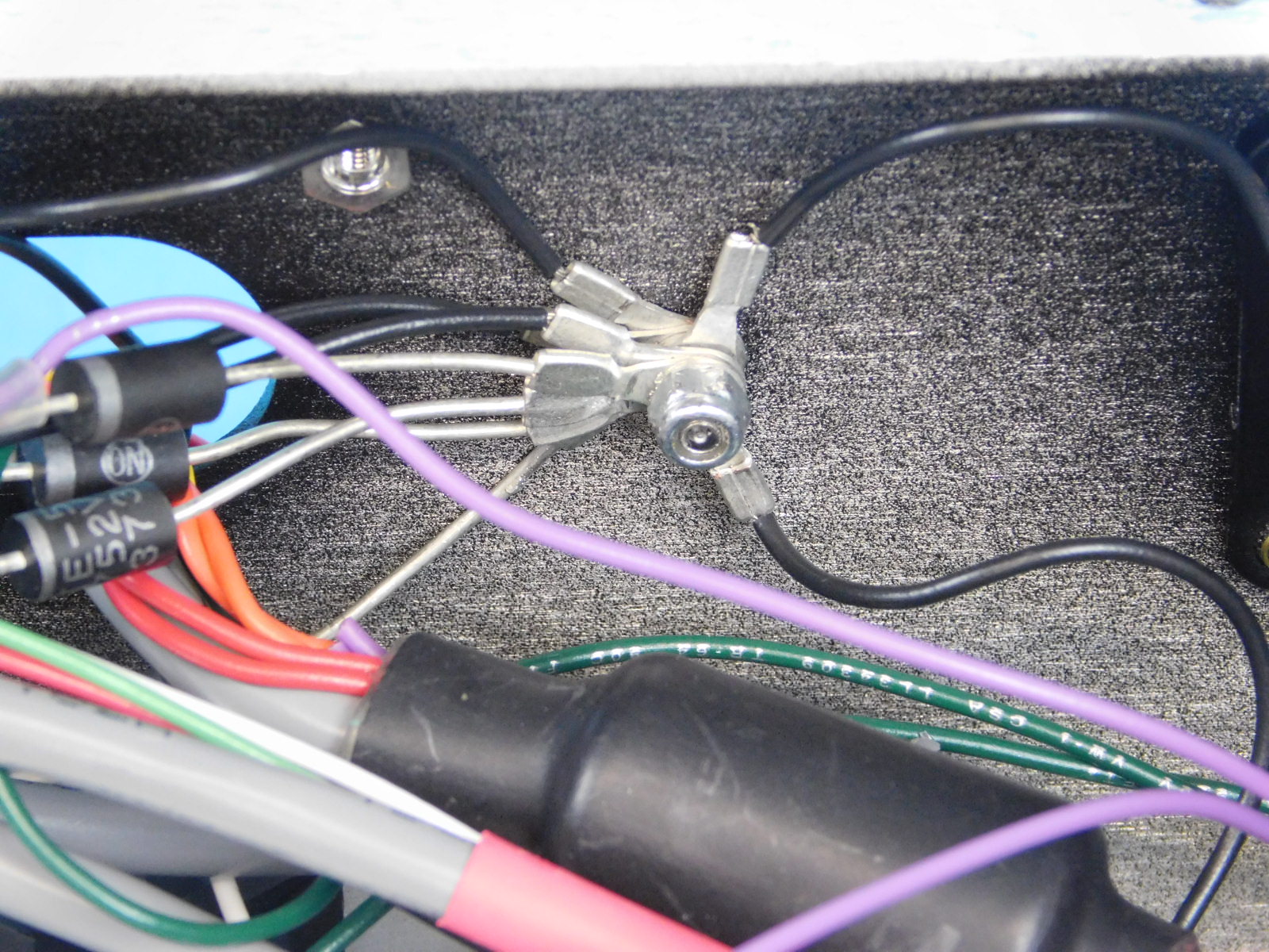
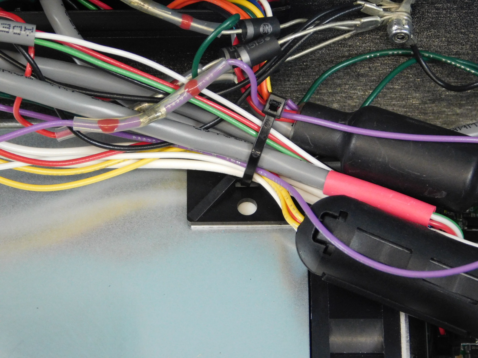
Secure the two black leads and the two white leads to the cable tie downs on the PSU using two zip ties [HD-MS0058] as pictured.
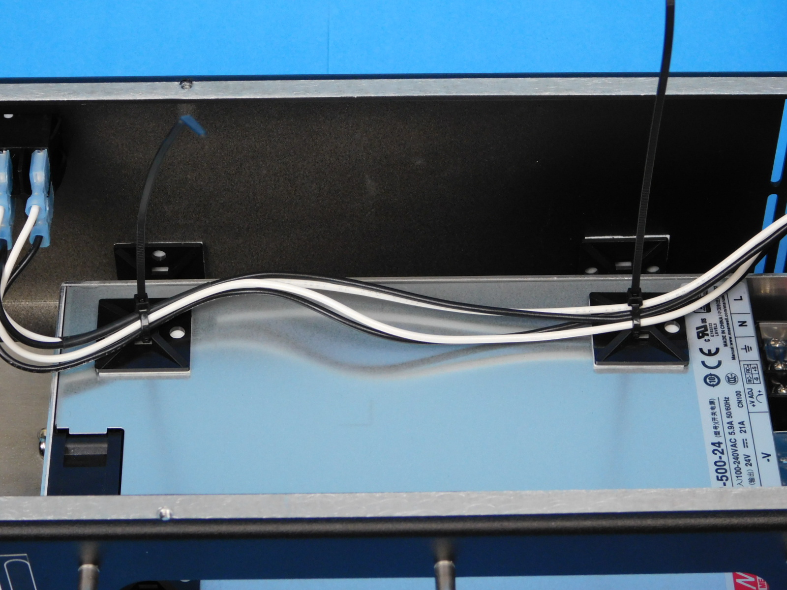
Route the CB DC Power Harness behind the black/white leads and the ground.
Secure the 2x- black/2x- white leads to the tie down on the bottom of the chassis, as pictured.
Secure the CB DC Power Harness to the front wall as pictured using two (2) zip ties [HD-MS0058]
Connect the blue spade terminal of the Plug to Ground harness [EL-HR0167] to the top terminal on the receptacle.
Before handling any PCB or LCD assemblies, ensure you are properly grounded and that all handling of PCB or LCD assemblies is protected:
a) Use of ESD wrist straps is required any time a PCB or LCD is handled outside of a silver ESD protective bag, including but not limited to when they are installed inside assemblies. Ensure the inner metal button of the wrist strap is contacting your skin.
b) All work should be performed upon an ESD work mat
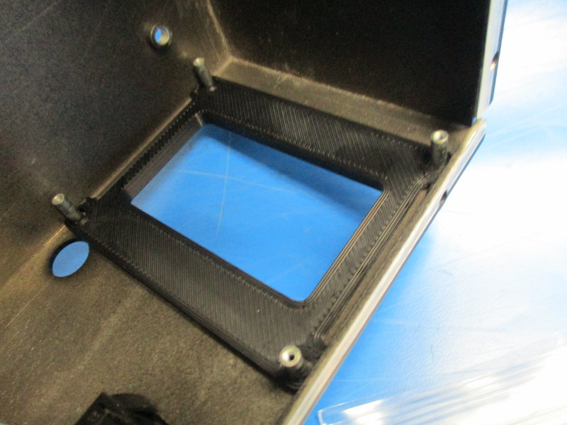
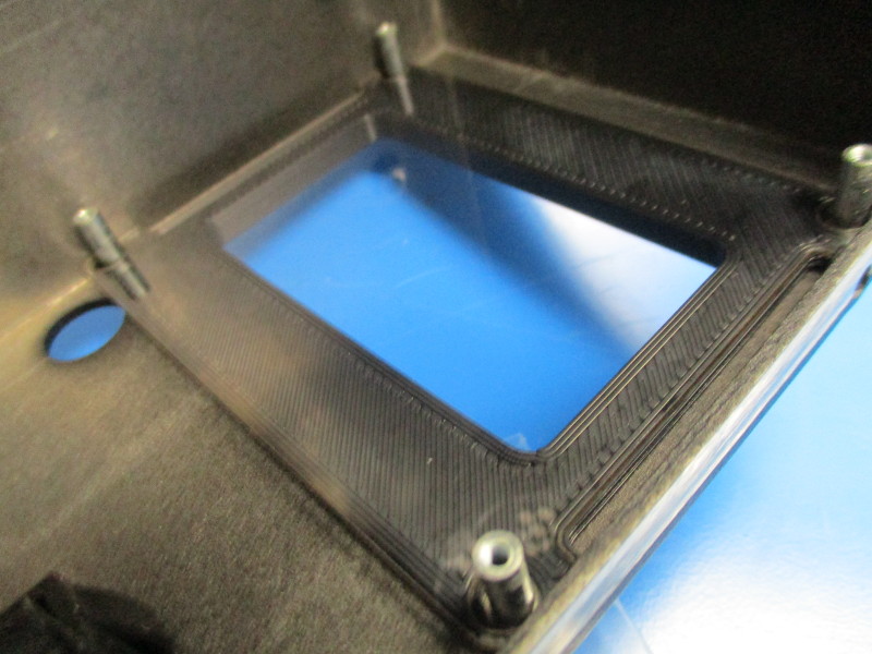
Install LCD bezel against the case, then the LCD screen protector against the LCD bezel
Remove LCD clear protective plastic
Install printed LCD spacers into LCD assembly screw mount hole locations (4x);
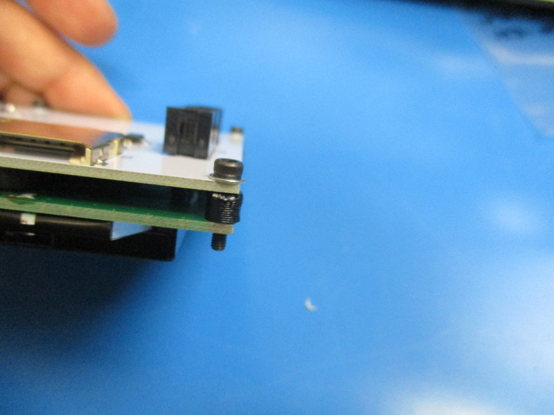
Install 4x- M2.5x12 SHCS and 4x- M2.5 washers into the four mount holes in the corners of the LCD PCBA
Align LCD with mounting standoffs- install screws to 3in*lbs
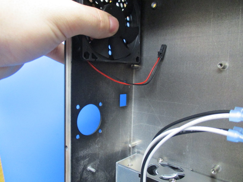
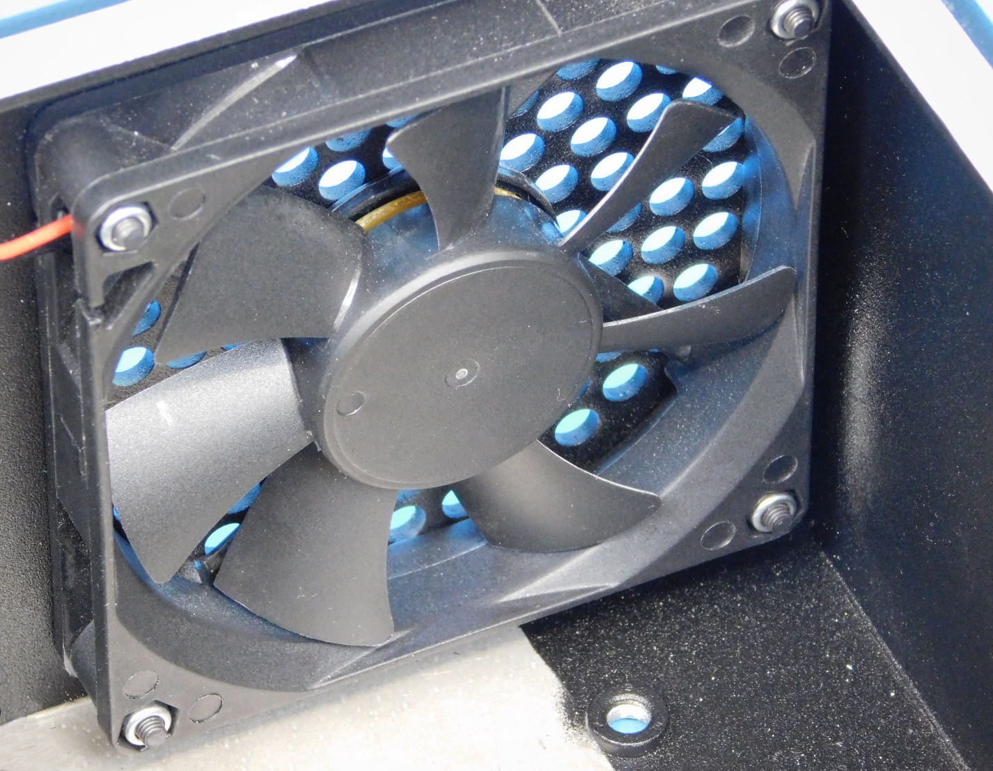
Install fan [EL-FA0061] with the fan label facing toward the inner wall of the control box, wiring exiting the fan away from the case top. Use 4x M3x20 BHCS [HD-BT0171] with washers [HD-WA0038] and 4x M3 Nyloc nuts [HD-NT0001] to secure the fan to the case. Hand tighten.
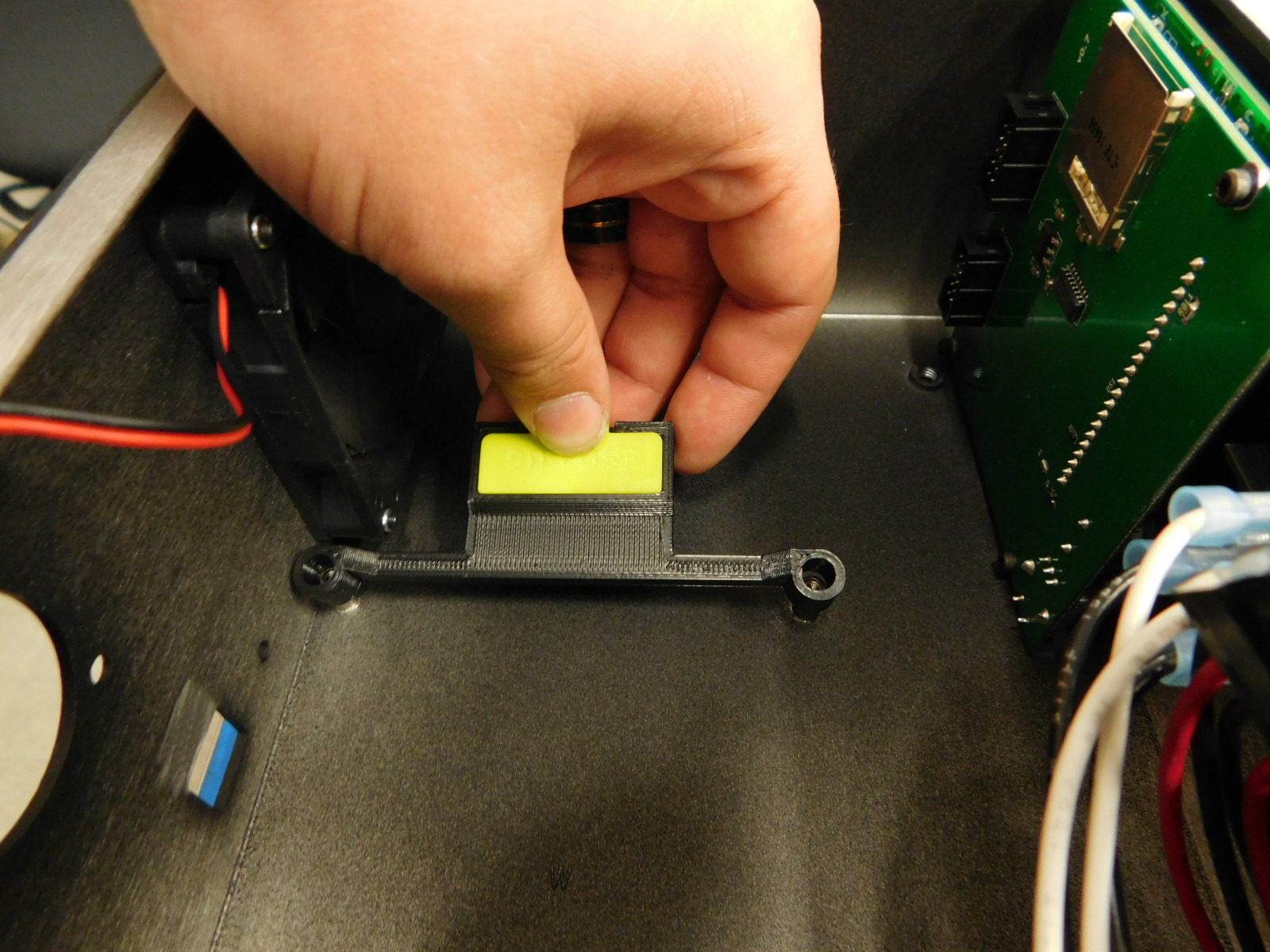
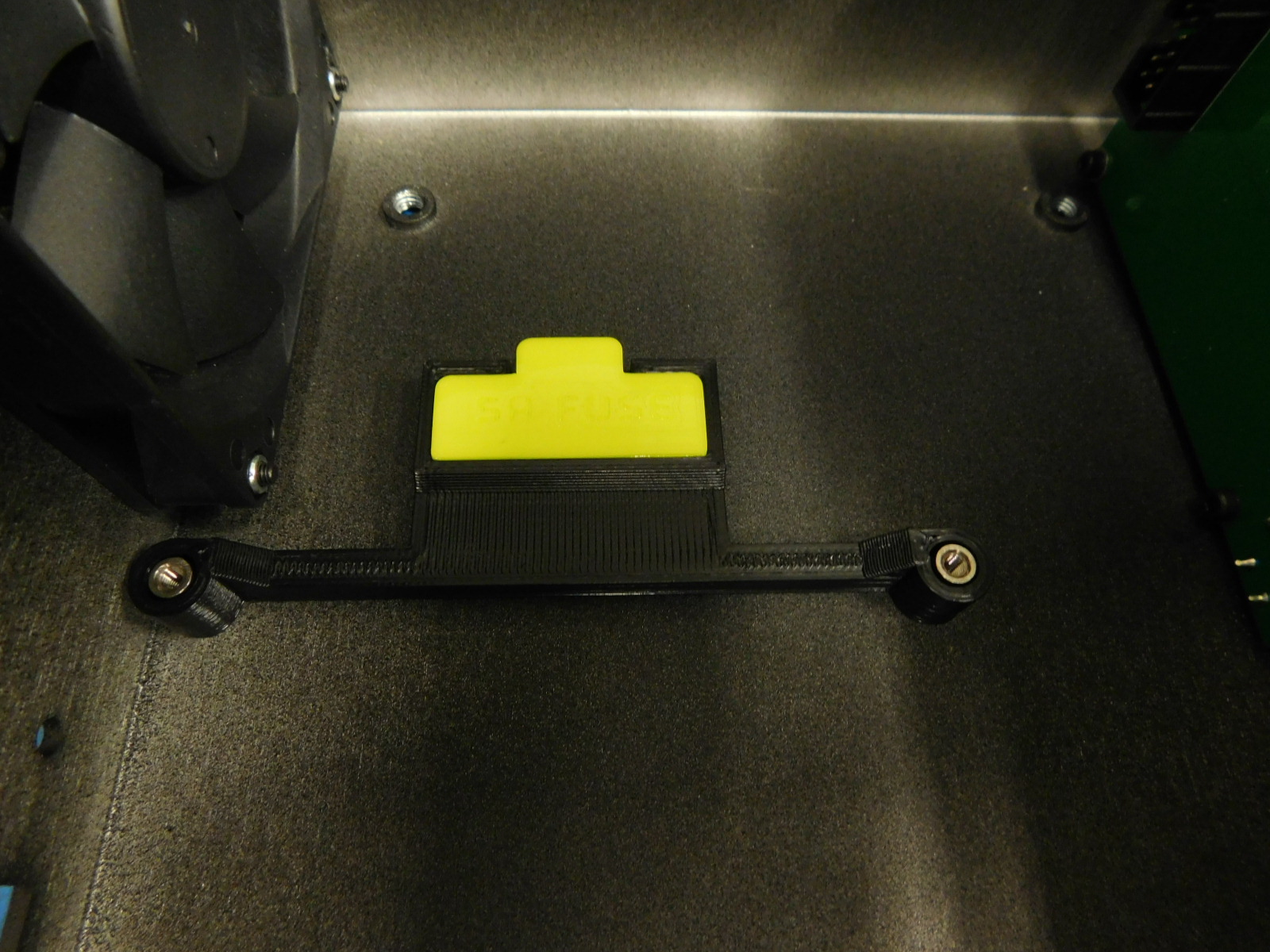
Obtain one 5A Fuse Mount Sub-assembly [AS-PR0169] and place it over the top two standoffs for mounting the RAMBo, as pictured.
See step 8 for ESD protection measures
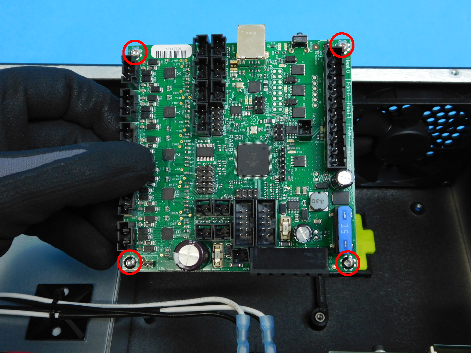
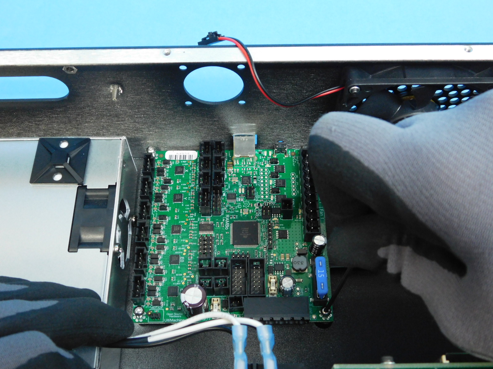
Obtain one RAMBo v1.4L PCBA [PC-BD0094]
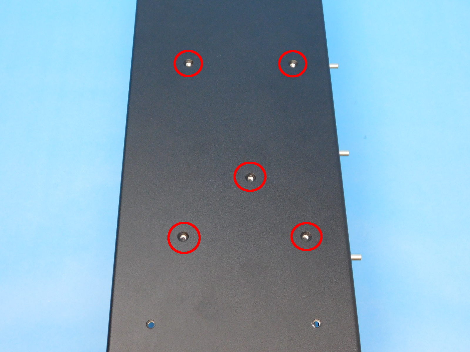
Place one M3x8 Stainless BHCS [HD-BT0104] in the 4 highlighted holes.
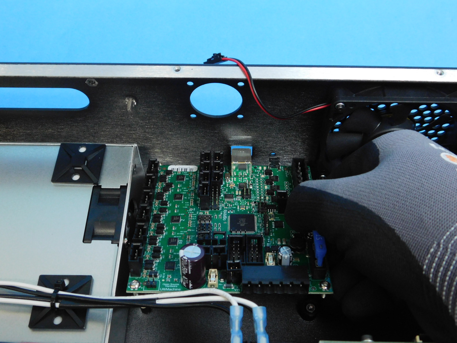
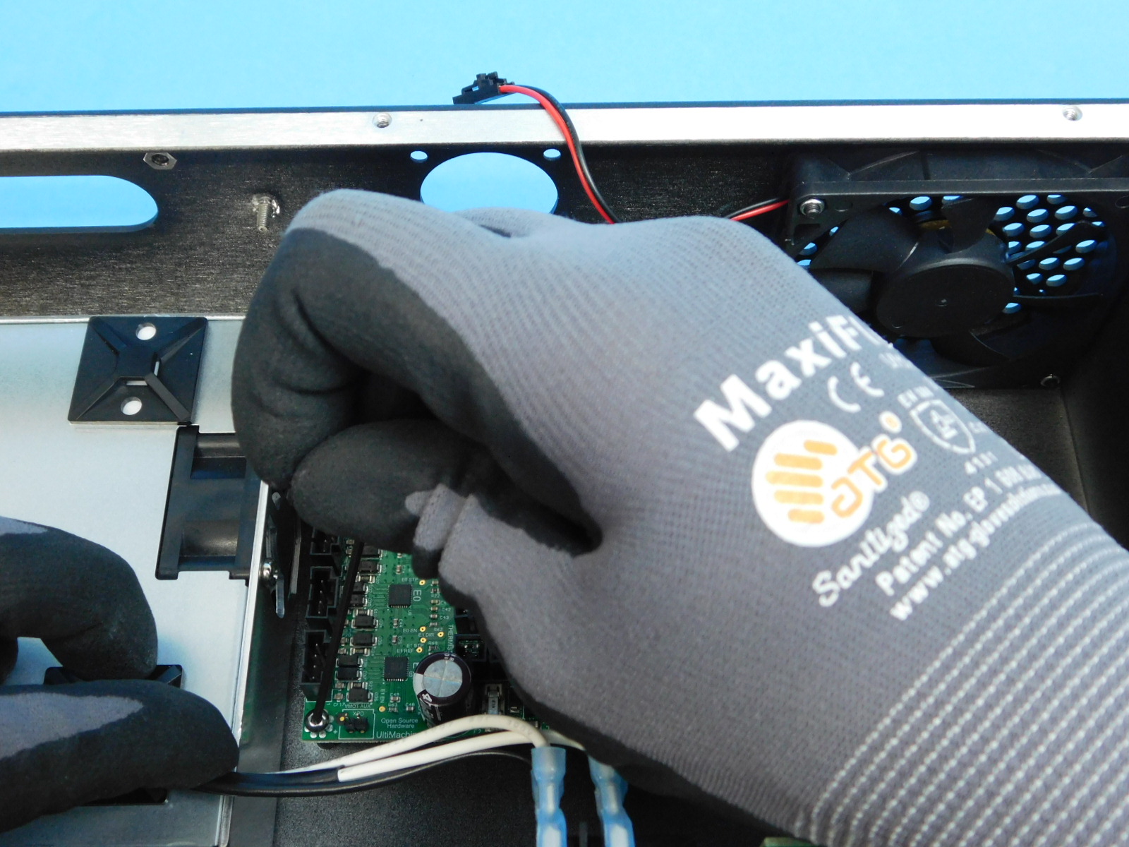
Lower the PCBA into the chassis as pictured.
Tighten all four screws securely.
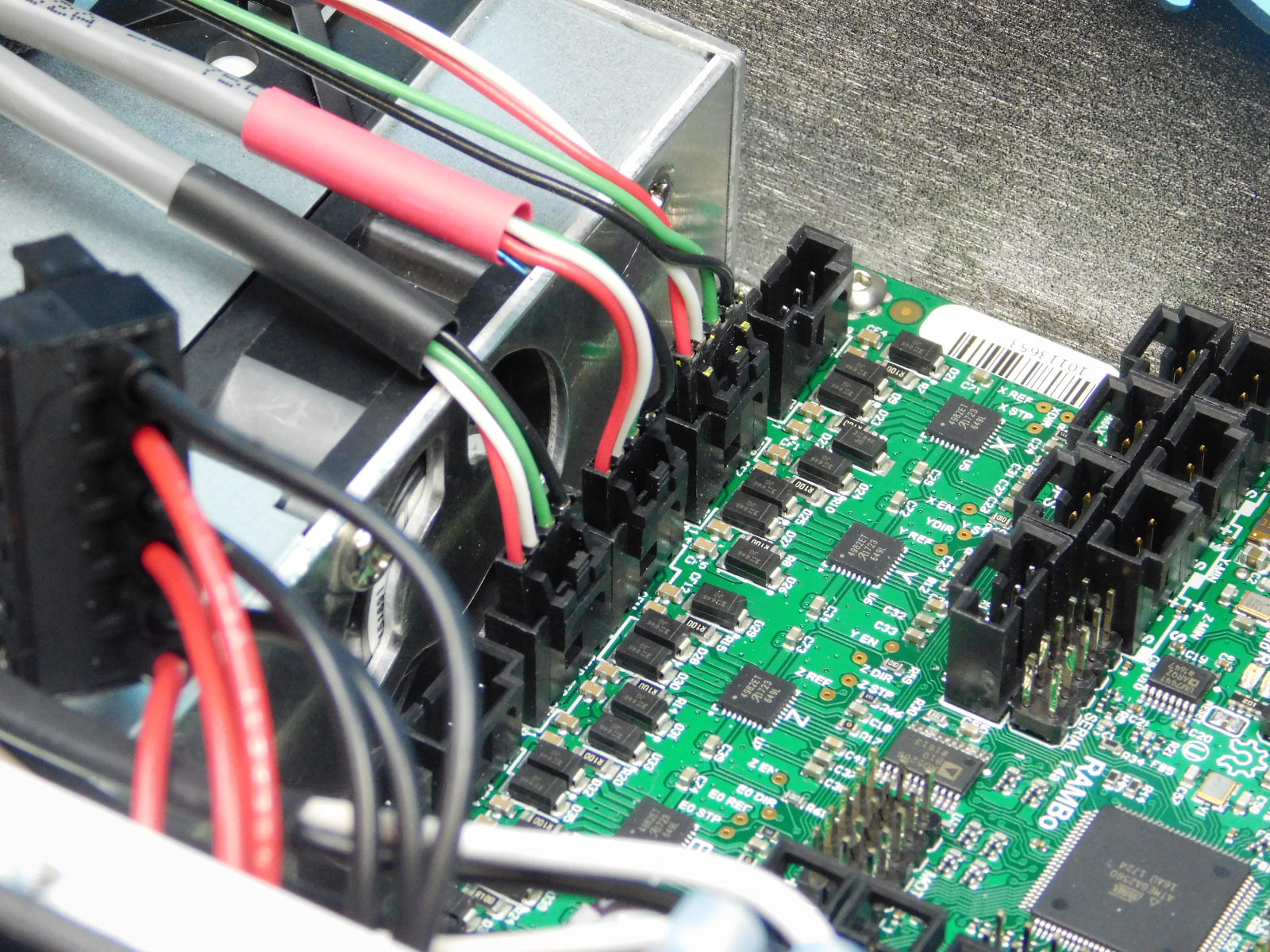
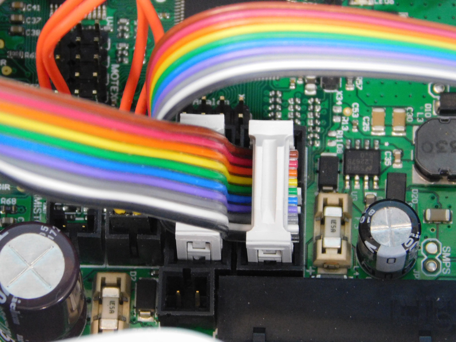
Connect the CB DC Power Harness to the RAMBo as pictured.
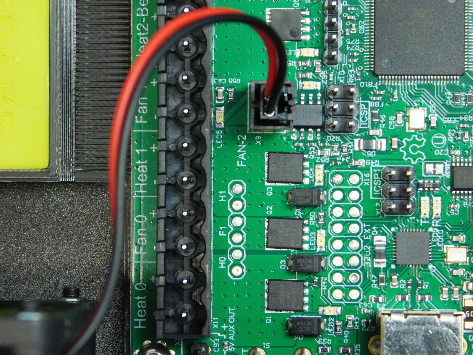
Plug fan into RAMBo
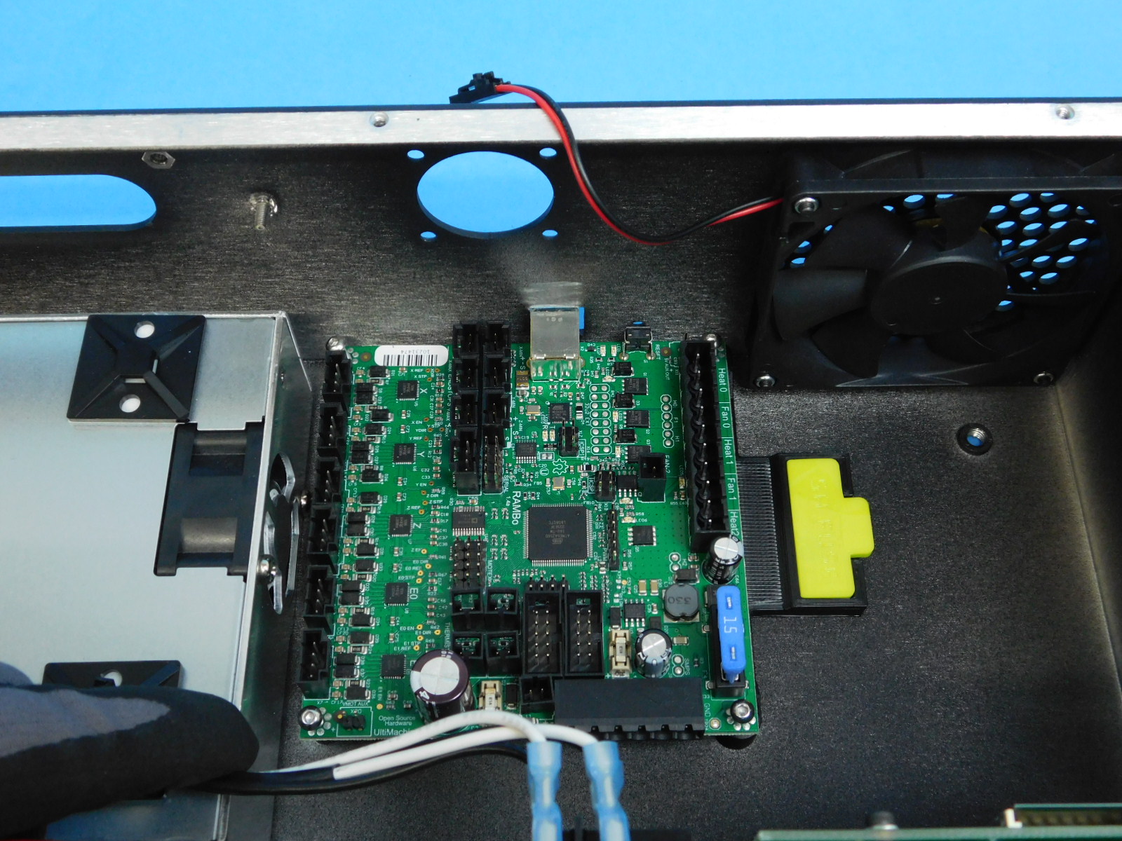
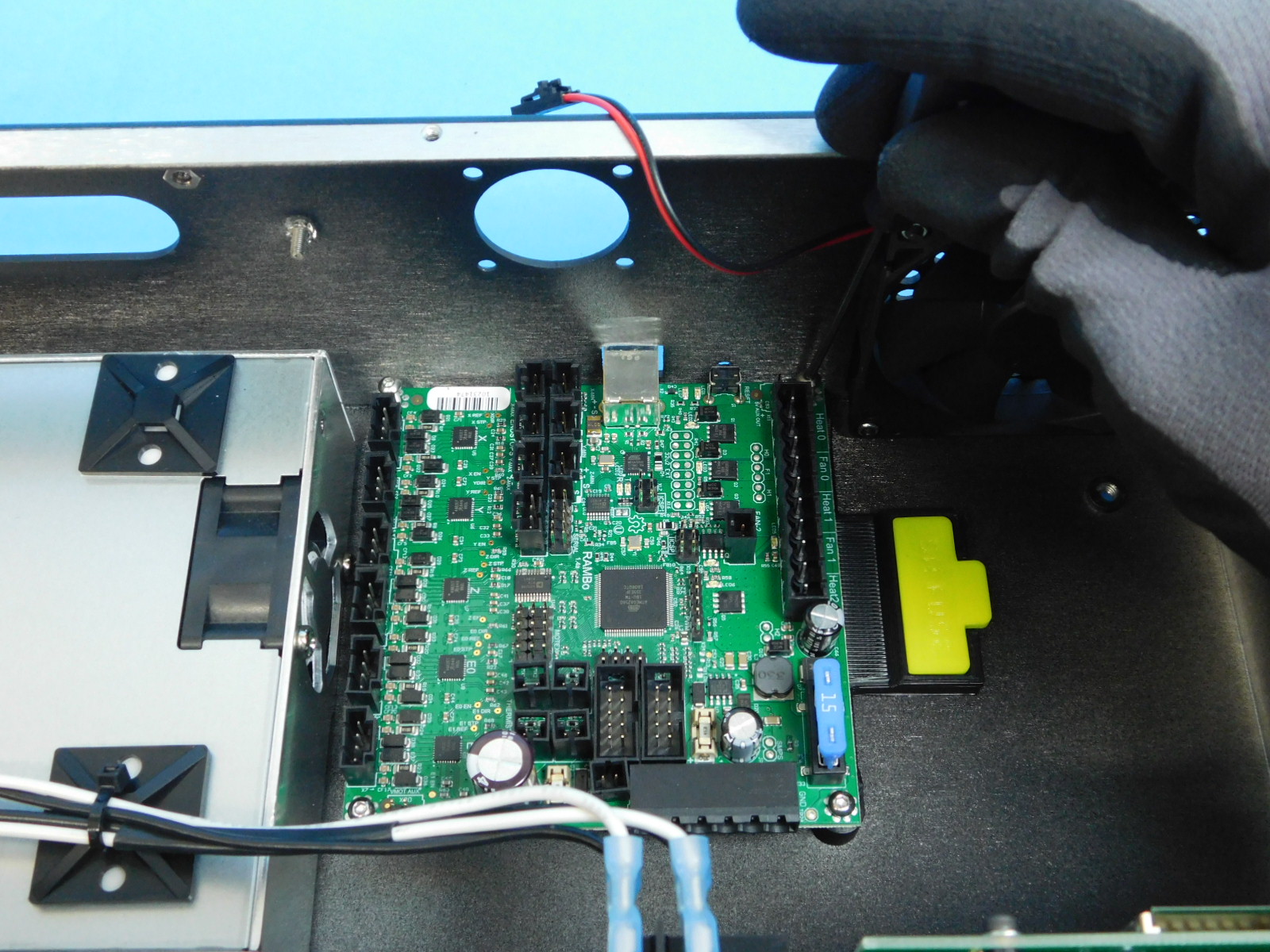
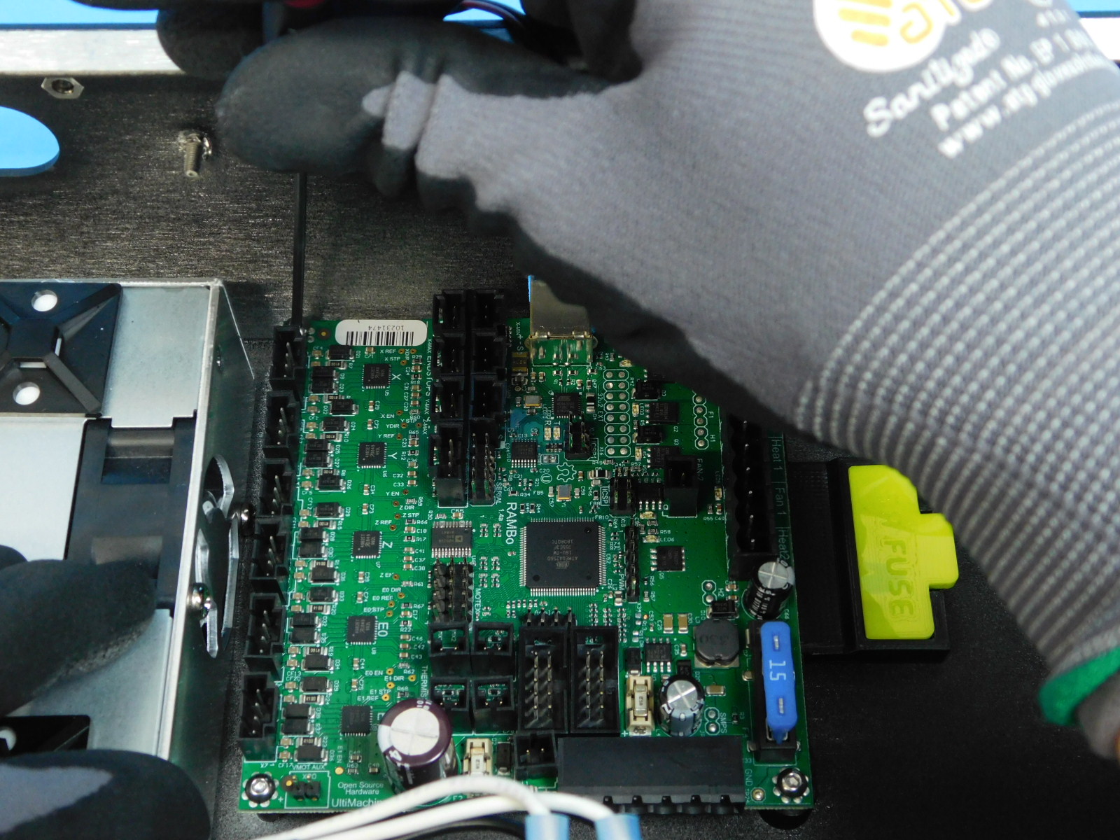
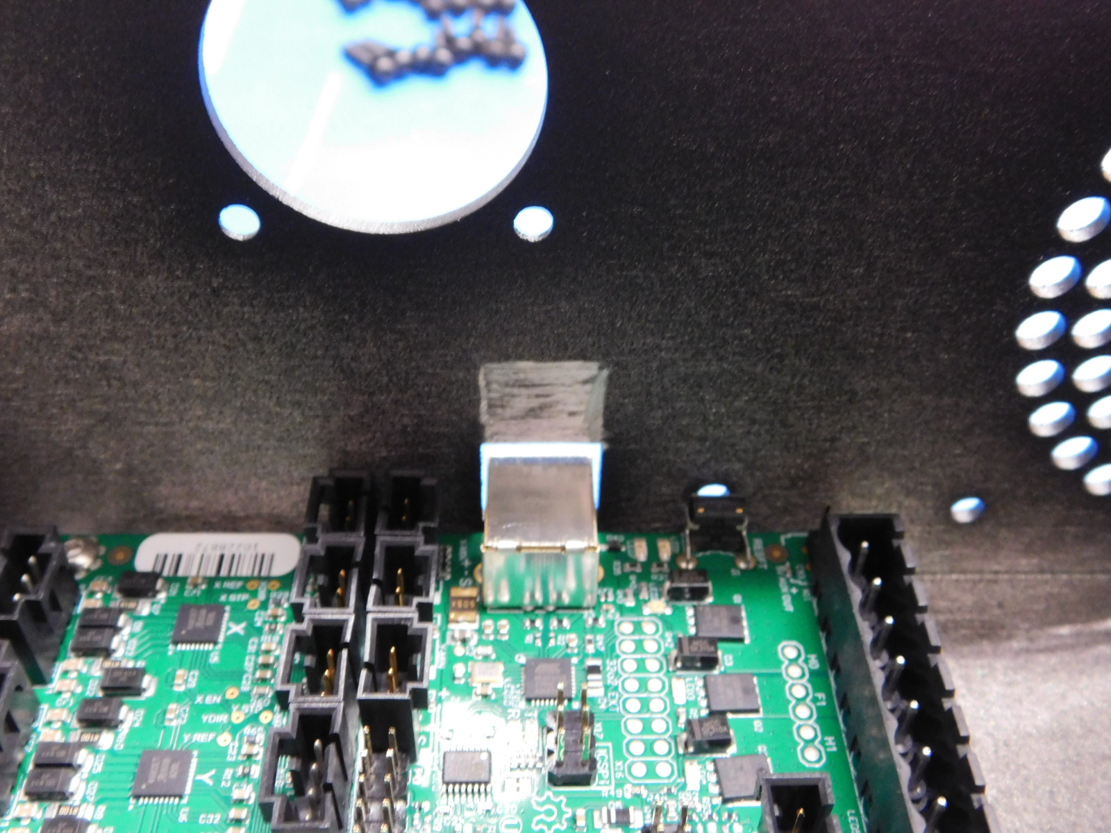
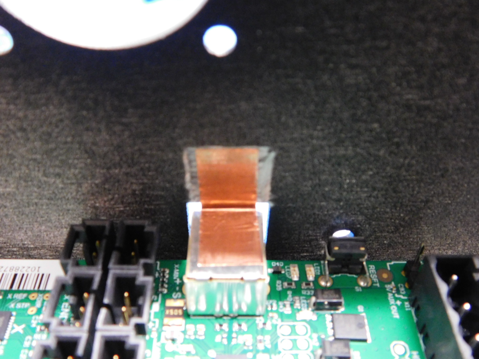
Add one strip of copper tape [10mm of EL-MS0560] to the RAMBo USB port as pictured.
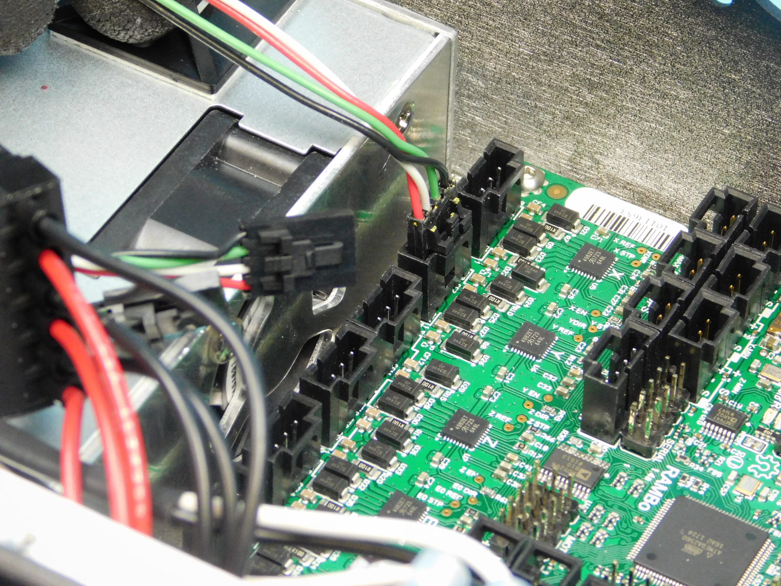
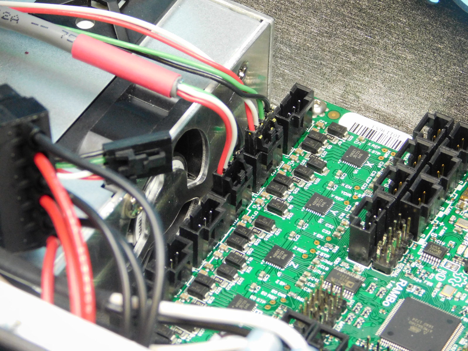
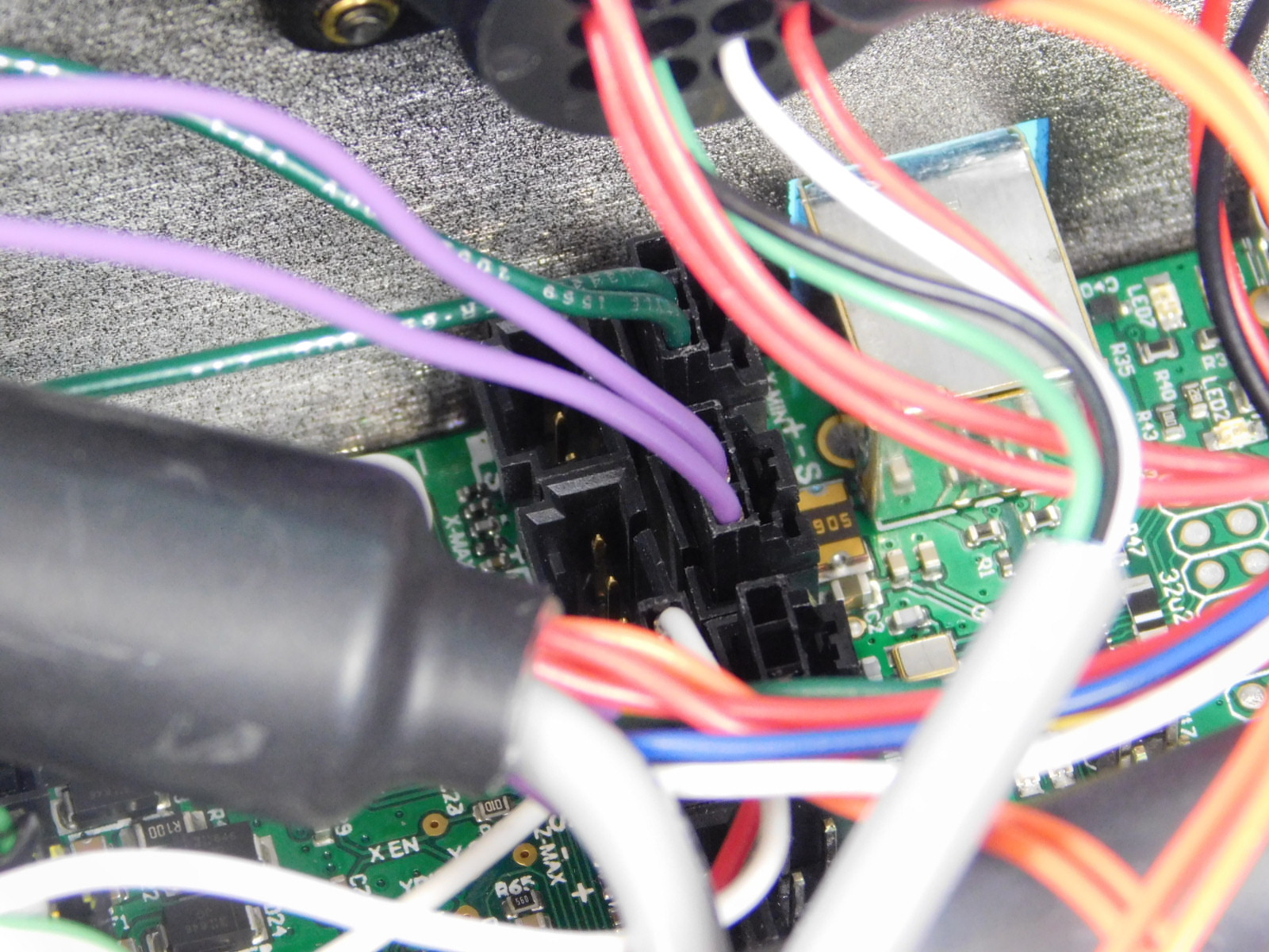
Obtain one CB Y/Z Harness [EL-HR0183]
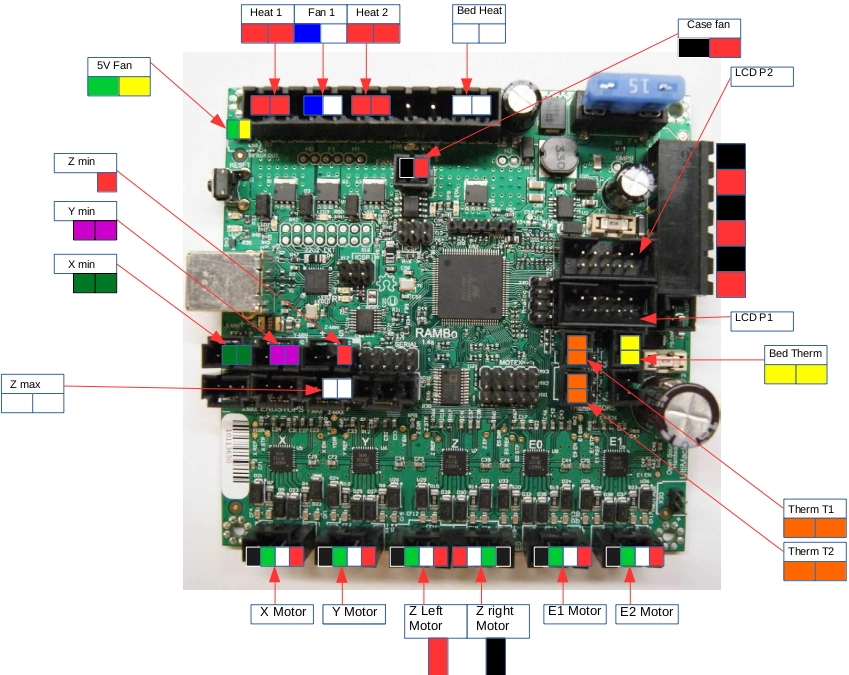
Begin by connecting the Y-Motor lead, this lead is the one without colored heat shrink. See pin out diagram.
Connect the Z Motors, lead with black heat shrink on left, lead with red heat shrink on right.
Verify locations by referencing the pin out diagram.
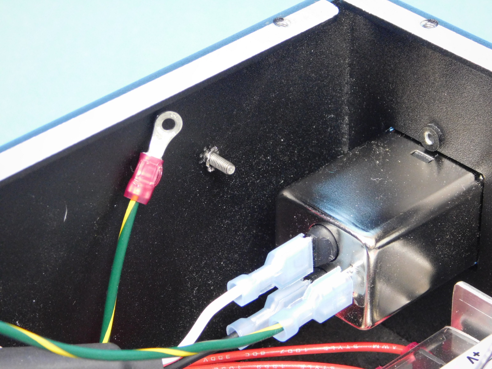
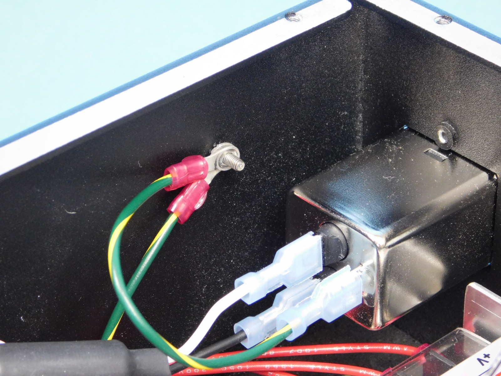
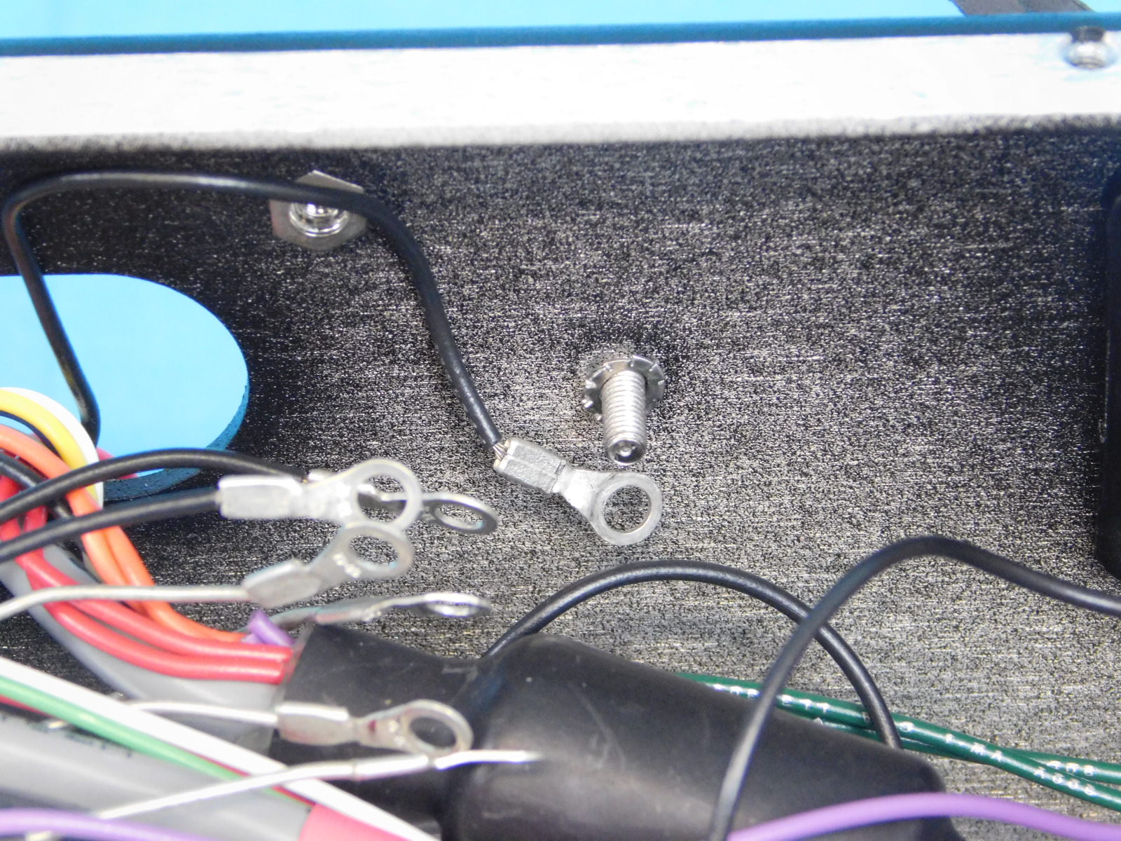
Install one Serrated Lock Washer [HD-WA0035] to the ground post on the bottom of the chassis
Attach the terminal rings from the two ground harnesses ([EL-HR0167] &[EL-HR0152])
Attach all three terminal rings from the Y/Z Harness [EL-HR0183] to the ground post on the bottom of the chassis and secure with one M3 Nyloc Nut [HD-NT0001]
Tighten securely.

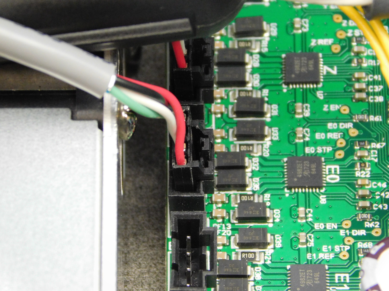
Obtain one CB Z Endstop Harness [EL-HR0185]
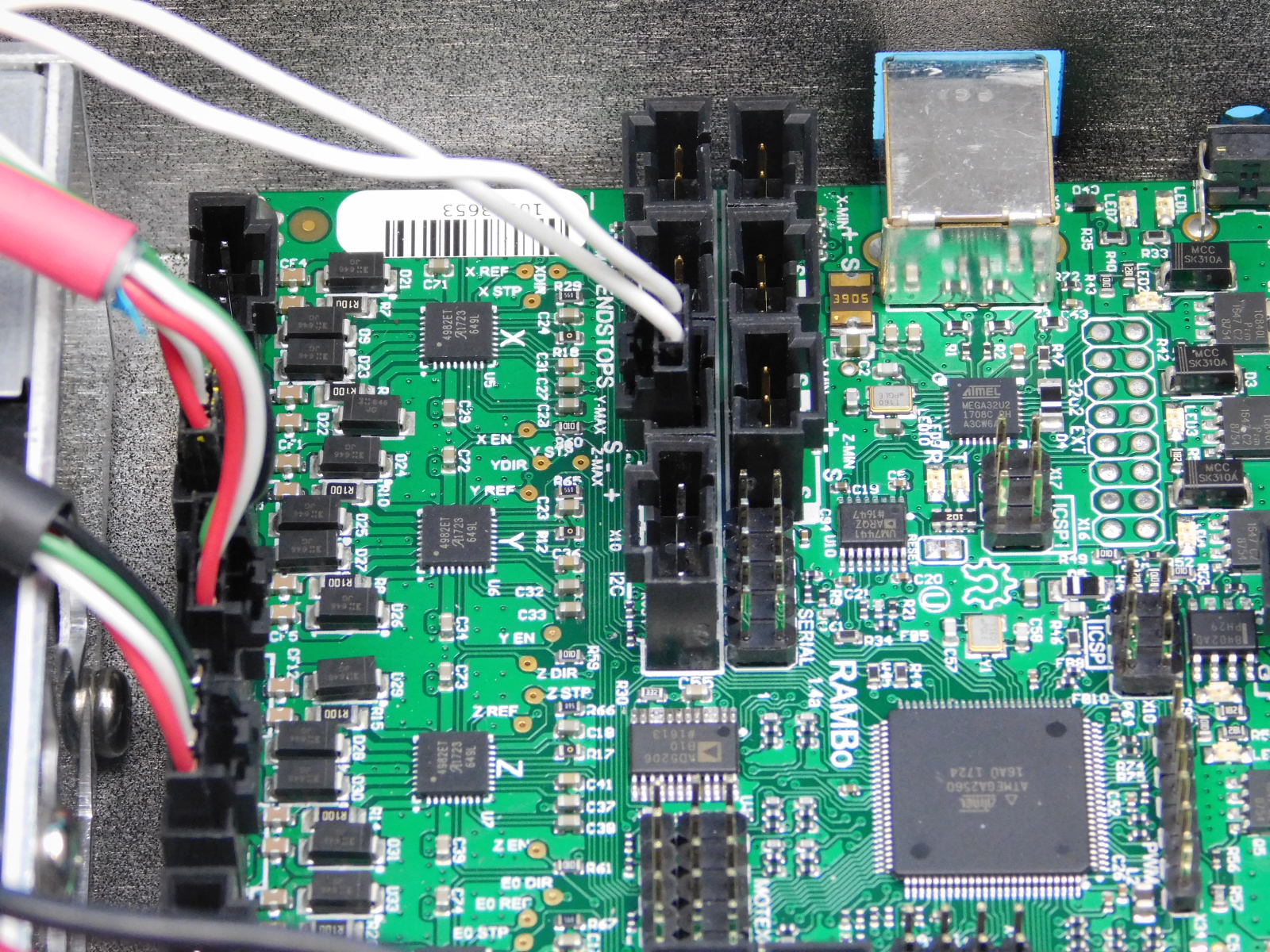
Connect the end of the harness with the 3-pin connector to the RAMBo at the location shown.
Place the other end through the slot in the rear of the chassis.

Obtain one CB Bed Harness [EL-HR0184]
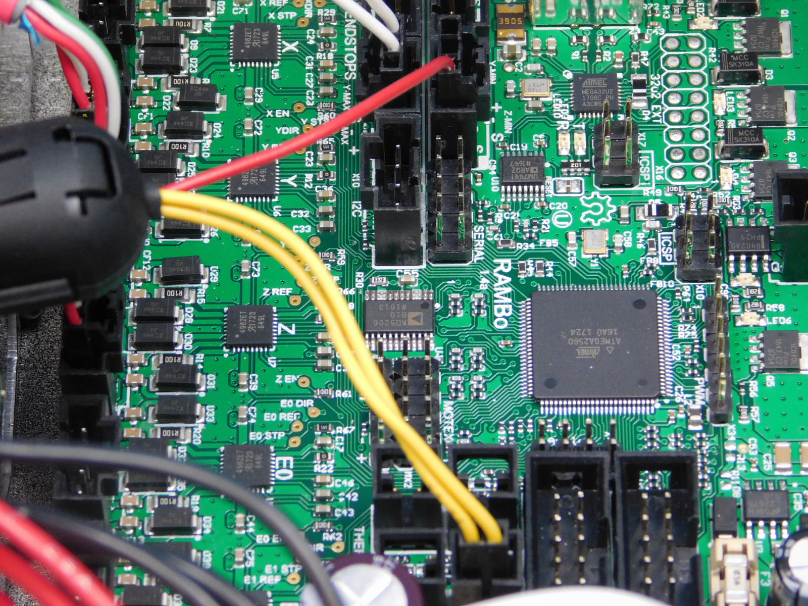
Connect the red lead with the 3 pin connector to the Z Min connector on the RAMBo; see diagram.
Connect the yellow lead with the 2 pin connector to the Bed Thermistor connector on the RAMBo; see diagram.

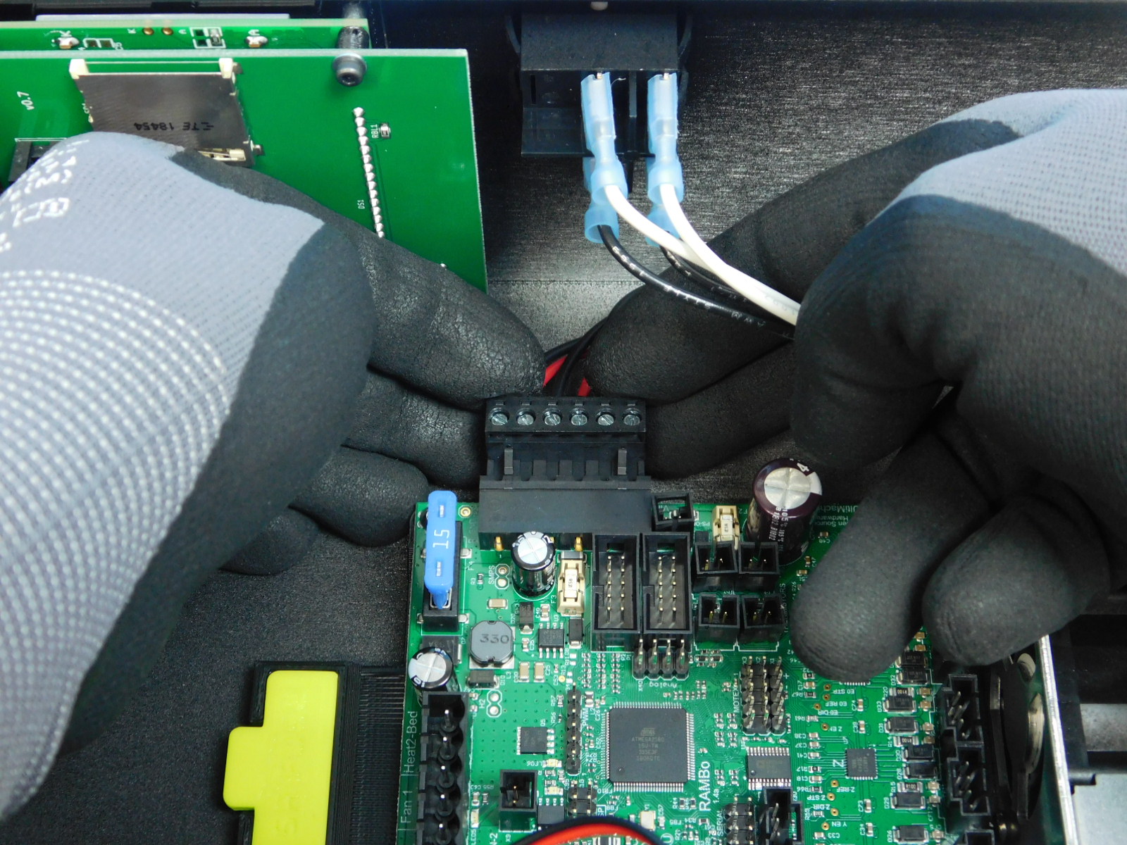
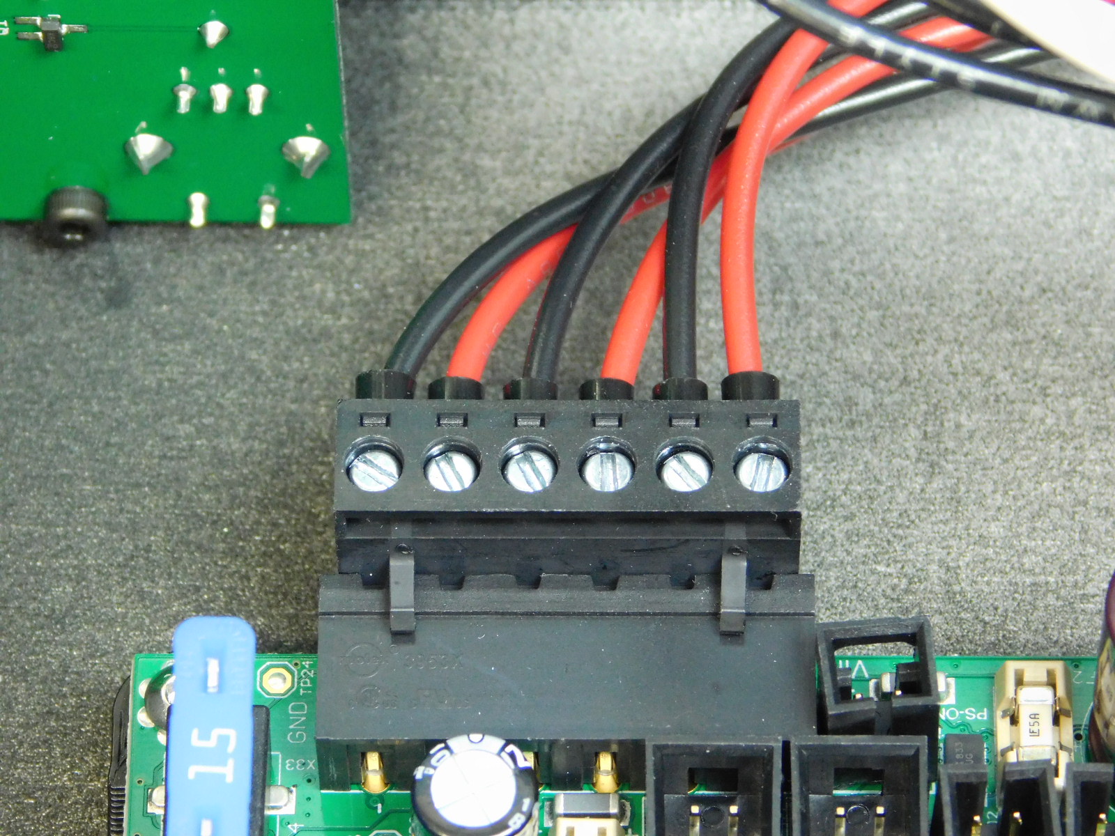
Obtain one CB Bed Power Harness [EL-HR0148]
Connect the terminal block end of the harness to the RAMBo; see diagram.
Place the other end of the harness through the slot in the rear of the chassis.

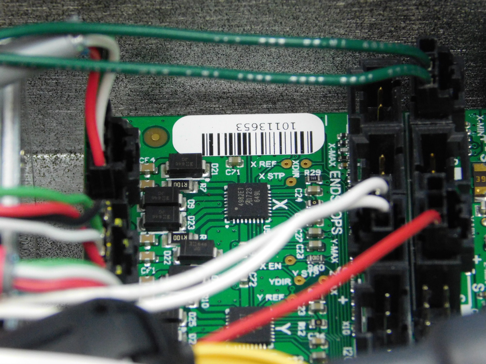
Obtain one CB X Harness [EL-HR0173]
Connect the 4 pin connector end of the harness to the X Motor connector on the RAMBo. This is located on the bottom left of the board.
Connect the 3 pin connector with green leads to the X Min Endstop position on the RAMBo.
See pin out diagram.
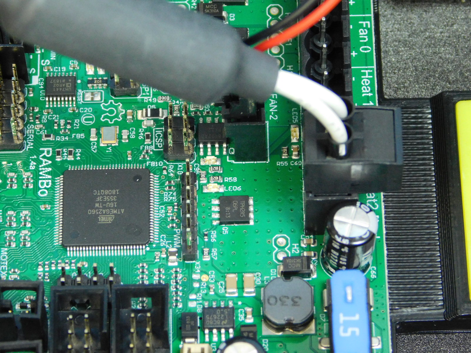
Obtain one CB Extruder Harness [EL-HR0175]
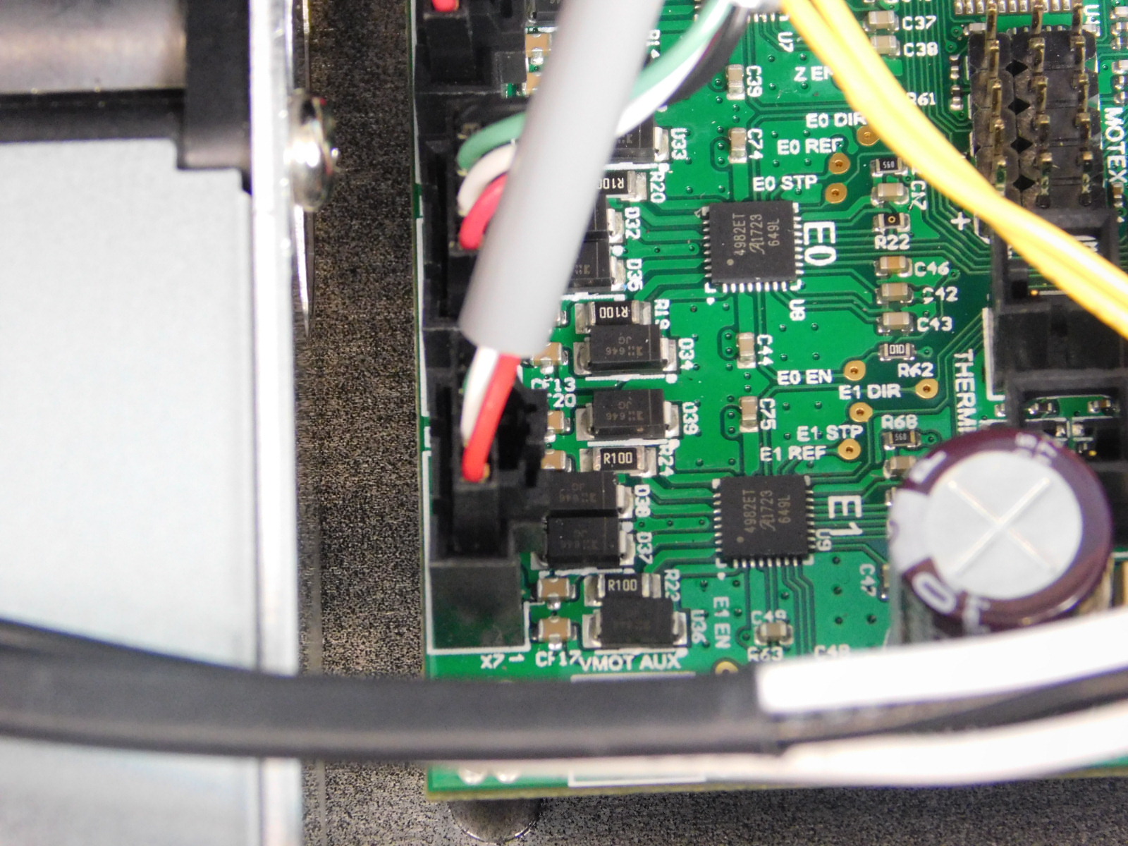
Connect the gray shielded lead with 4 pin connector to the E1 connector on the RAMBo.
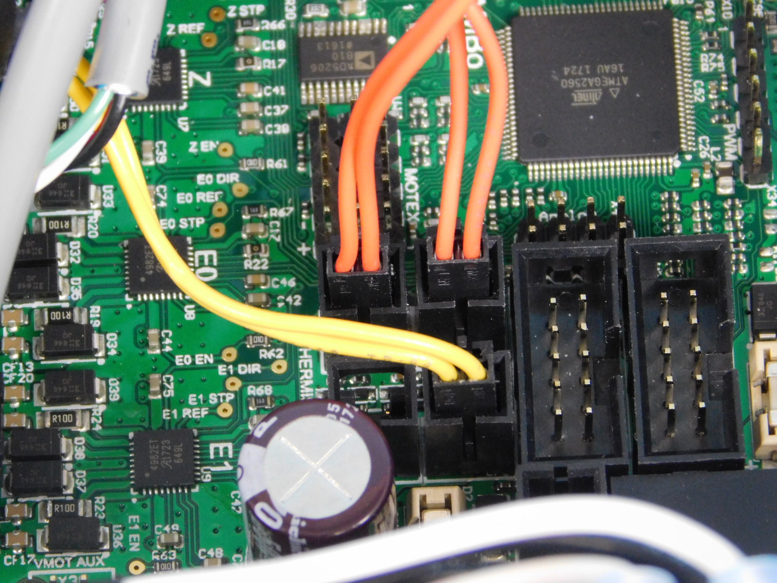
Connect the double orange lead with 2 pin connector to the T1 Thermistor connector on the RAMBo.
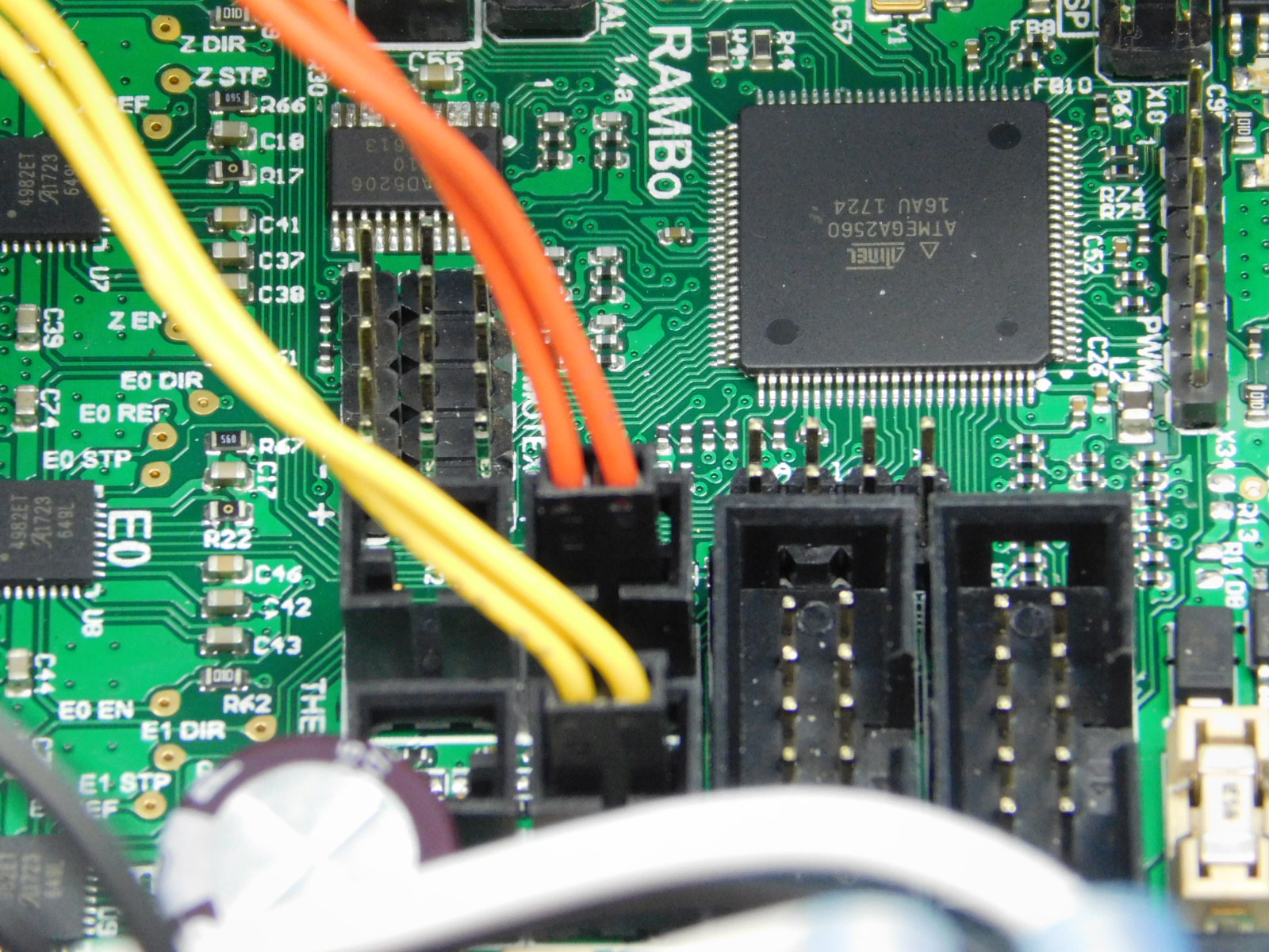
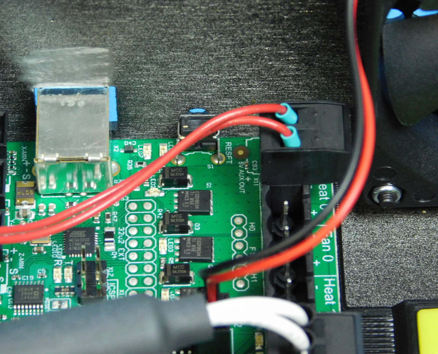
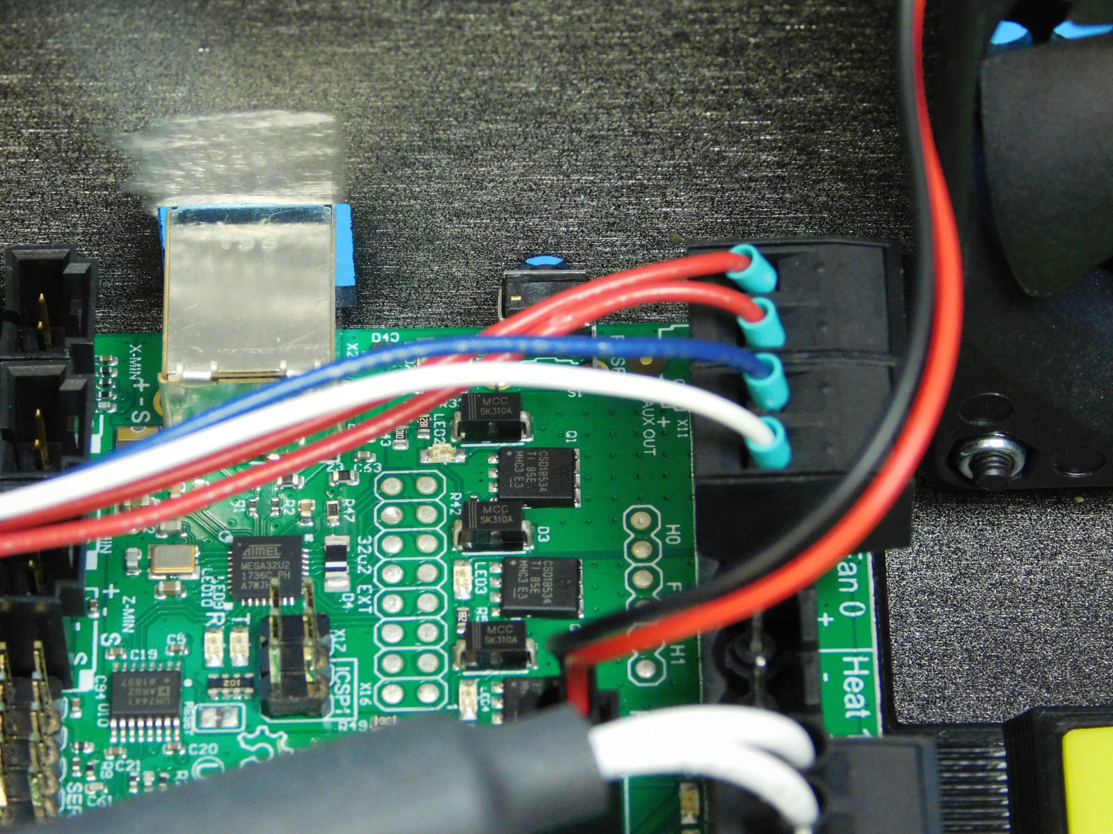
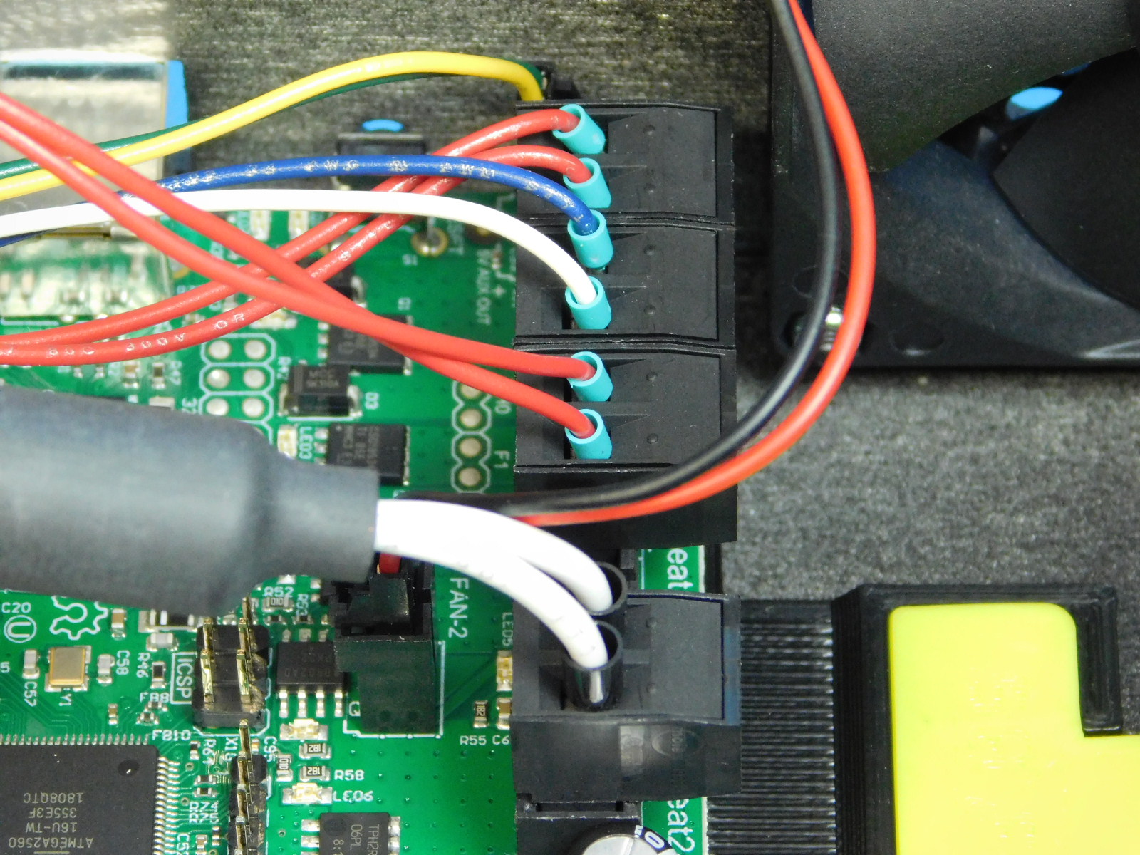
Carefully route the heater lead (double red lines in 2 position terminal block) and 24v fan lead (blue/white lines in 2 position terminal block) so that no unnecessary tension is applied when the connector is plugged in.
Connect the double red lead to the left-most terminal block position as pictured.
Connect the blue/white lead to the next terminal block position to the right, as pictured.
Connect the yellow/green lead (5v Fan) to the 2 pin header at the top left of the RAMBo, as pictured.
The clip of the connector should be facing the top of the chassis.

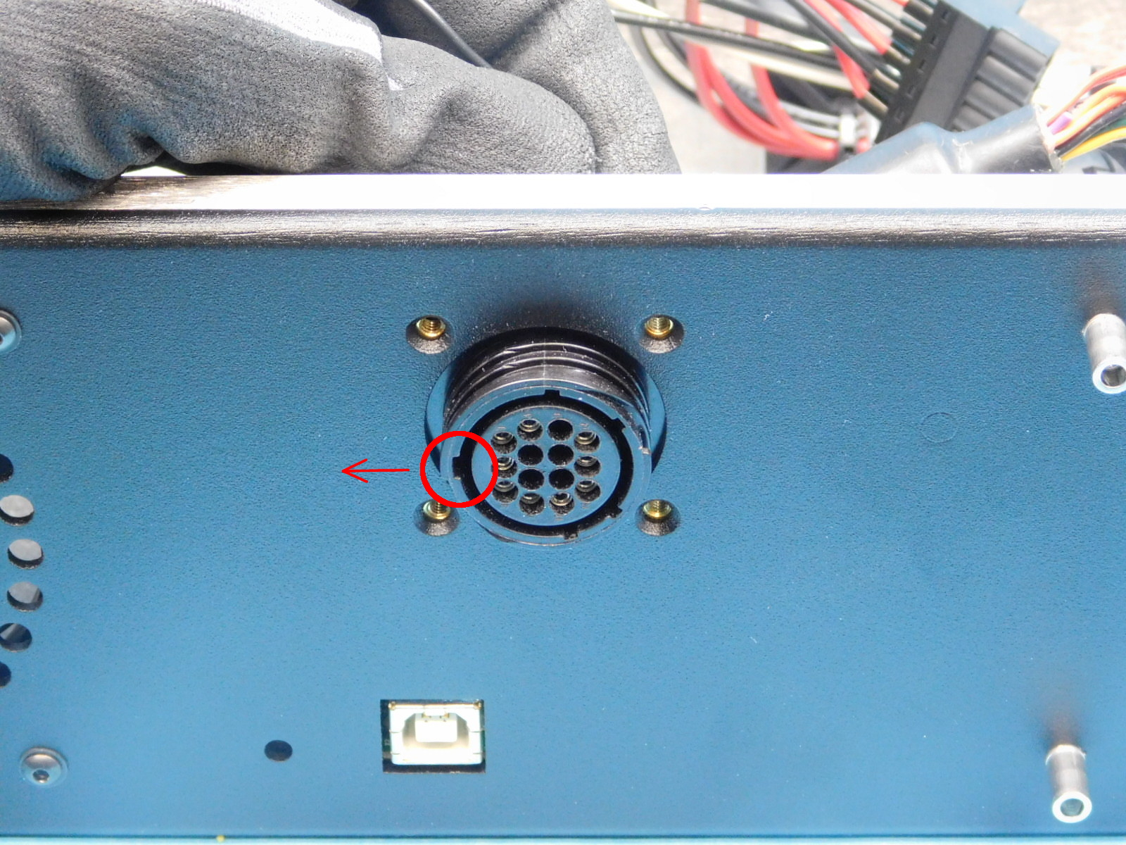
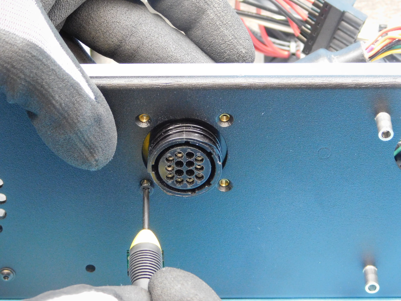
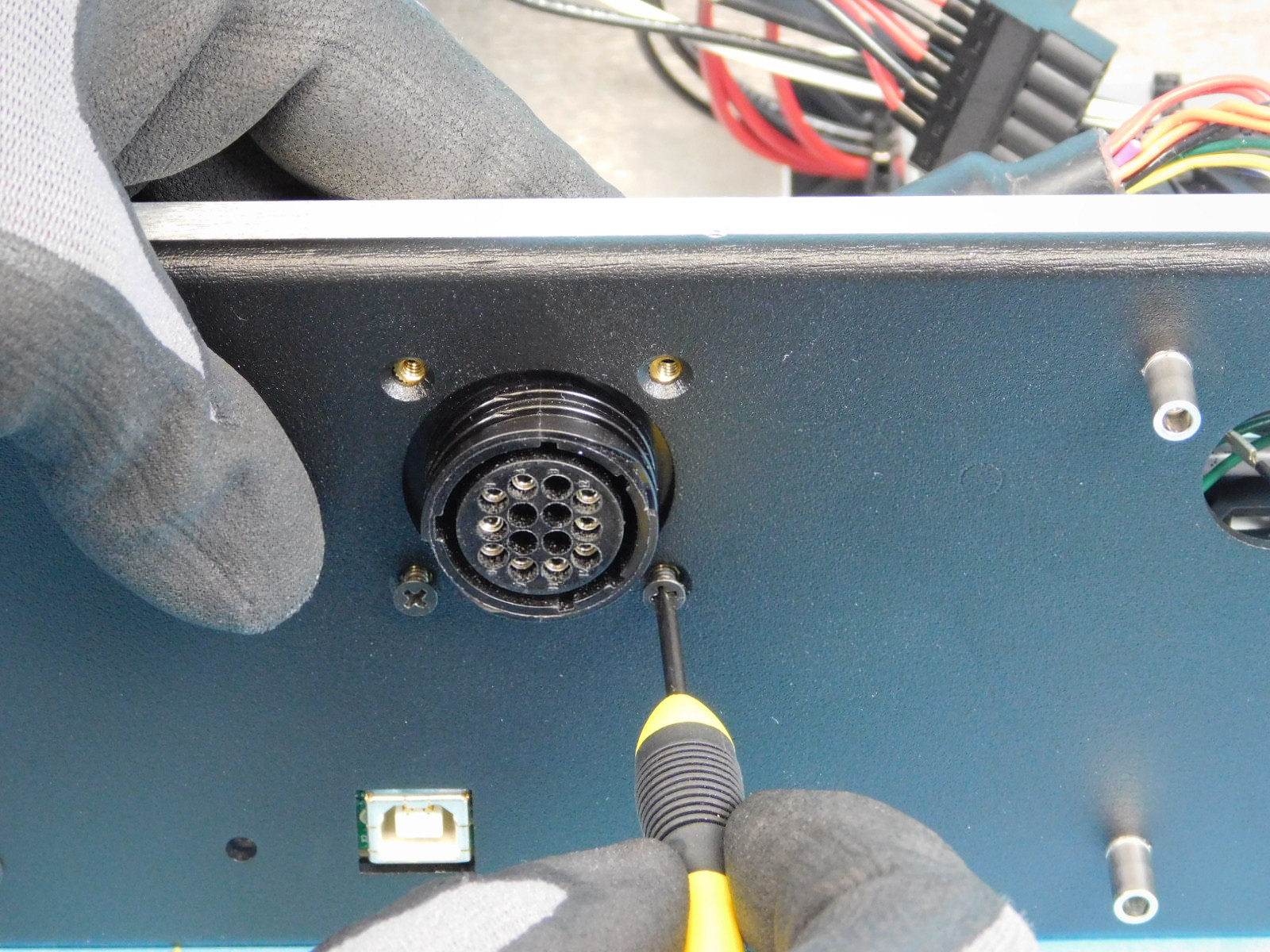
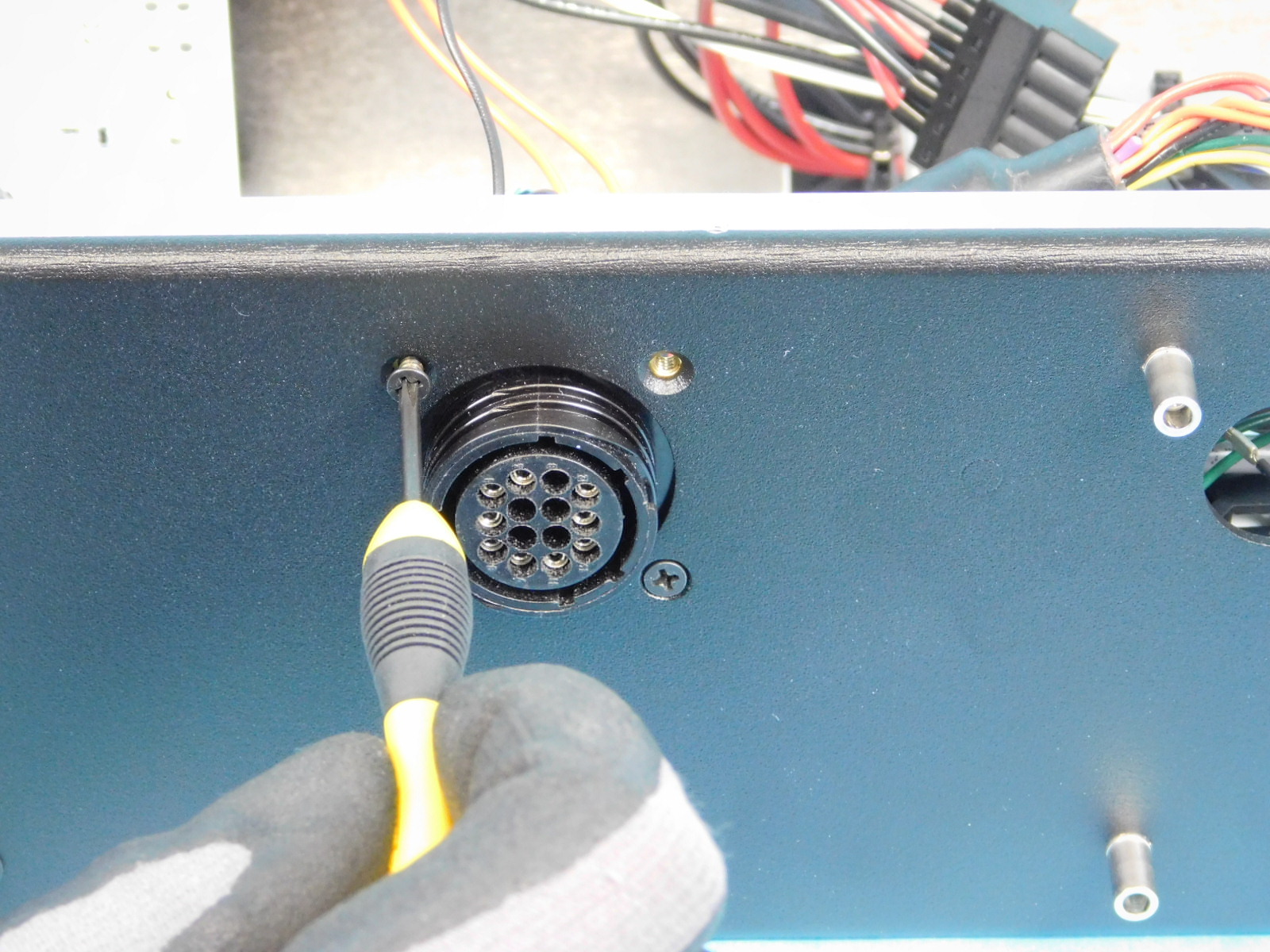
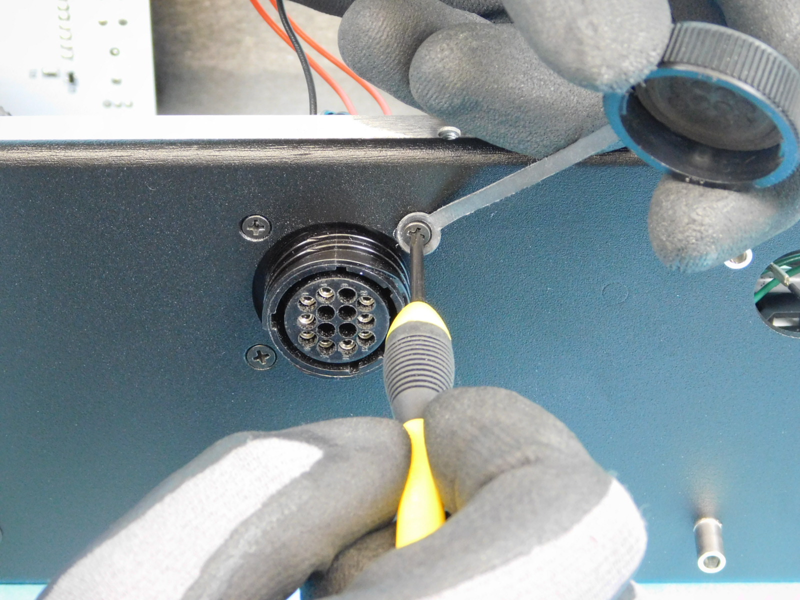
Install the CB Dual Extruder harness [EL-HR0176] from the inside the case, set the orientation of the connector so the widest alignment tab is facing the top of the chassis; see photo.
Secure the connector with 3x- 18-8 FHS Black Oxide [HD-BT0053]; tighten to 3in*lbs
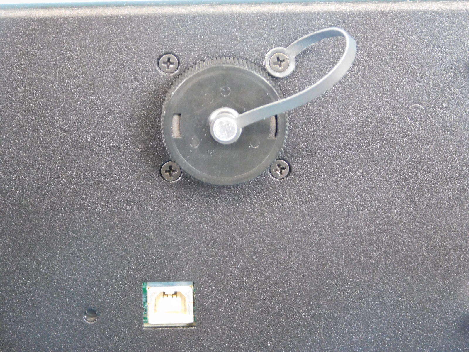
Position the EL-MS0144 (Sealing Cap) strap so the strap will double over itself when the cap is installed onto the 16position round connector, secure the sealing cap with 1x- 18-8 FHS Black Oxide [HD-BT0053]; tighten to finger tight, the strap should not be able to rotate once tightened. Cover the connector with the sealing cap
Connect the gray shielded lead with 4 pin connector to the E2 connector on the RAMBo.
Connect the double orange lead with 2 pin connector to the T2 Thermistor connector on the RAMBo.
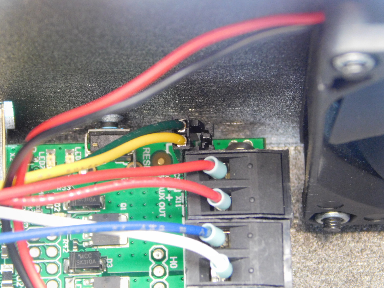
Connect the double red lead with 2 position terminal block to the Heat 2 position on the RAMBo, located to the right of the blue/white lead connected in the previous step.

Obtain one CB Y Endstop Harness [EL-HR0177]
Connect the end of the harness closest to the terminal ring to the RAMBo at the location shown.
Place the other end through the slot in the rear of the chassis

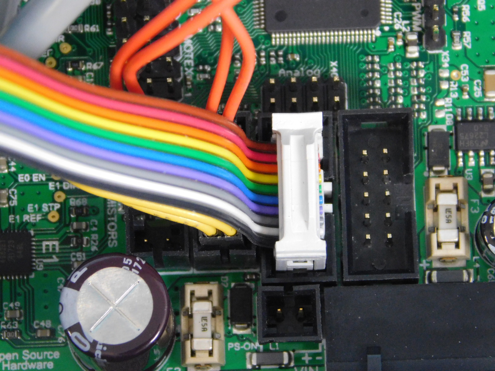
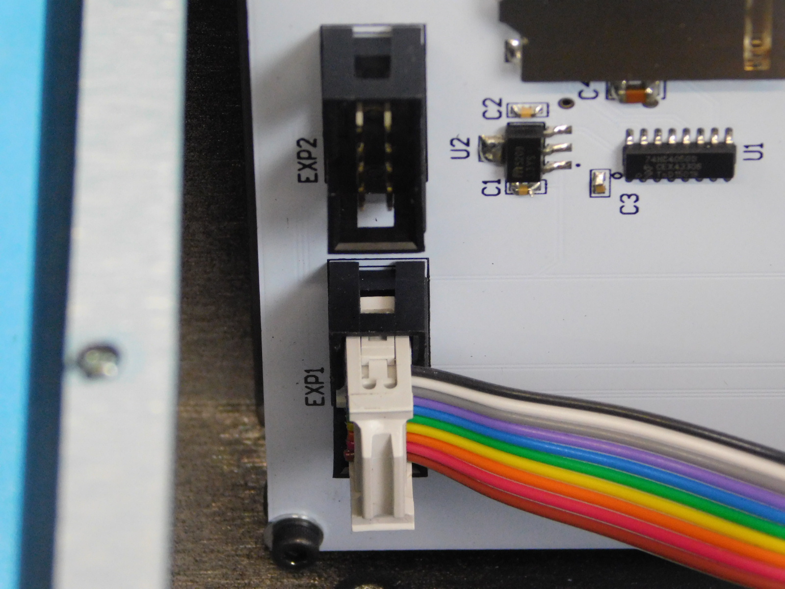
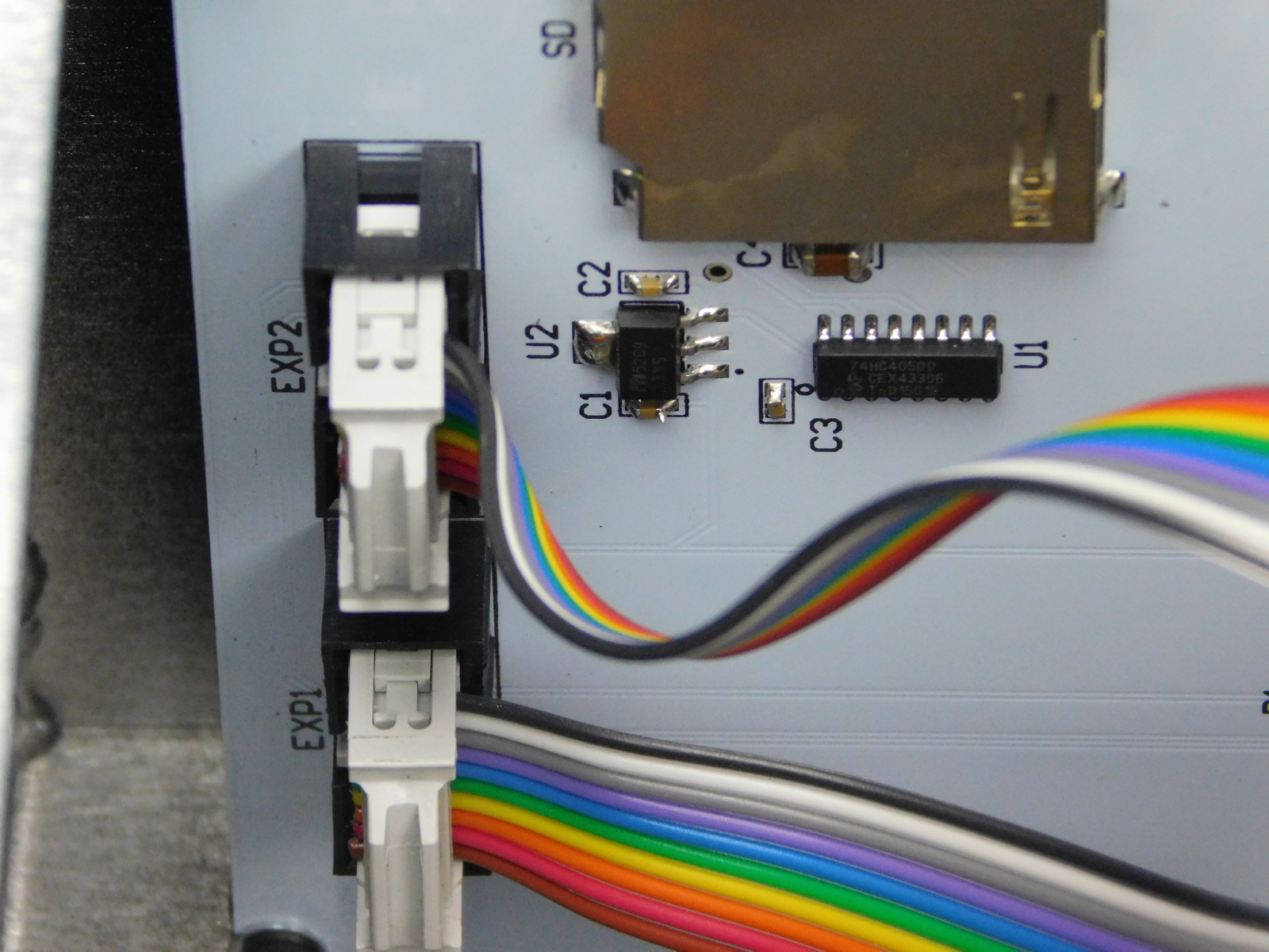
Obtain two (2) LCD/USB Harnesses [EL-HR0147]
Connect one to the RAMBo at the LCD P1 location shown and then to the EXP1 10 pin header of the LCD.
Connect another to the RAMBo at the LCD P2 location shown and then to the EXP2 10 pin header of the LCD.

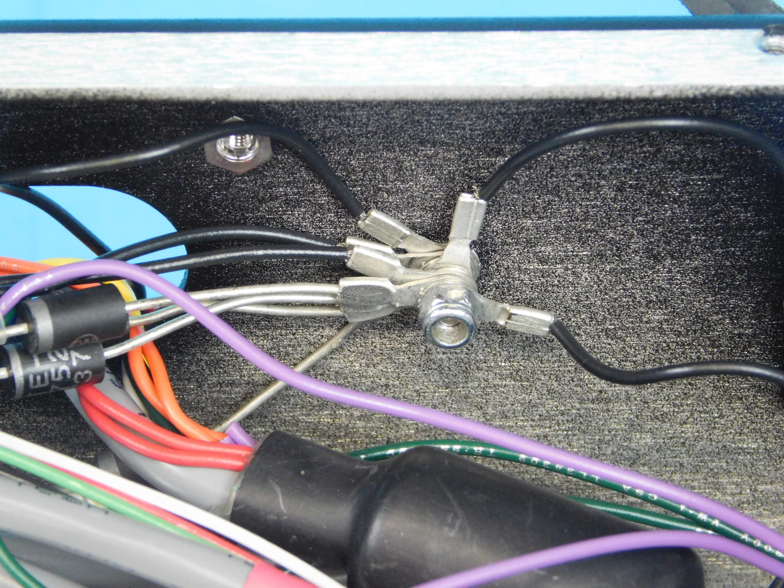
Gather all of the terminal rings, you should have 9 of them.
Apply one Serrated Lock Washer [HD-WA0035] to the ground post on the rear of the chassis.
Stack all 5 terminal rings on the post and secure with one M3 Nyloc Nut [HD-NT0001]
Tighten securely
Secure the harnesses to the tie down on the PSU using one zip tie [HD-MS0058] as pictured. It is not necessary to capture all of the grounds inside the zip tie.
To prevent the 5v Fan Connector from falling off during shipping of the final product, apply one zip-tie [HD-MS0058] around both wires of the 5v Fan lead and both wires of the E0 Heat lead, as shown.
Cut excess zip-tie flush with latch.
Ensure the connector remains fully seated on the pins
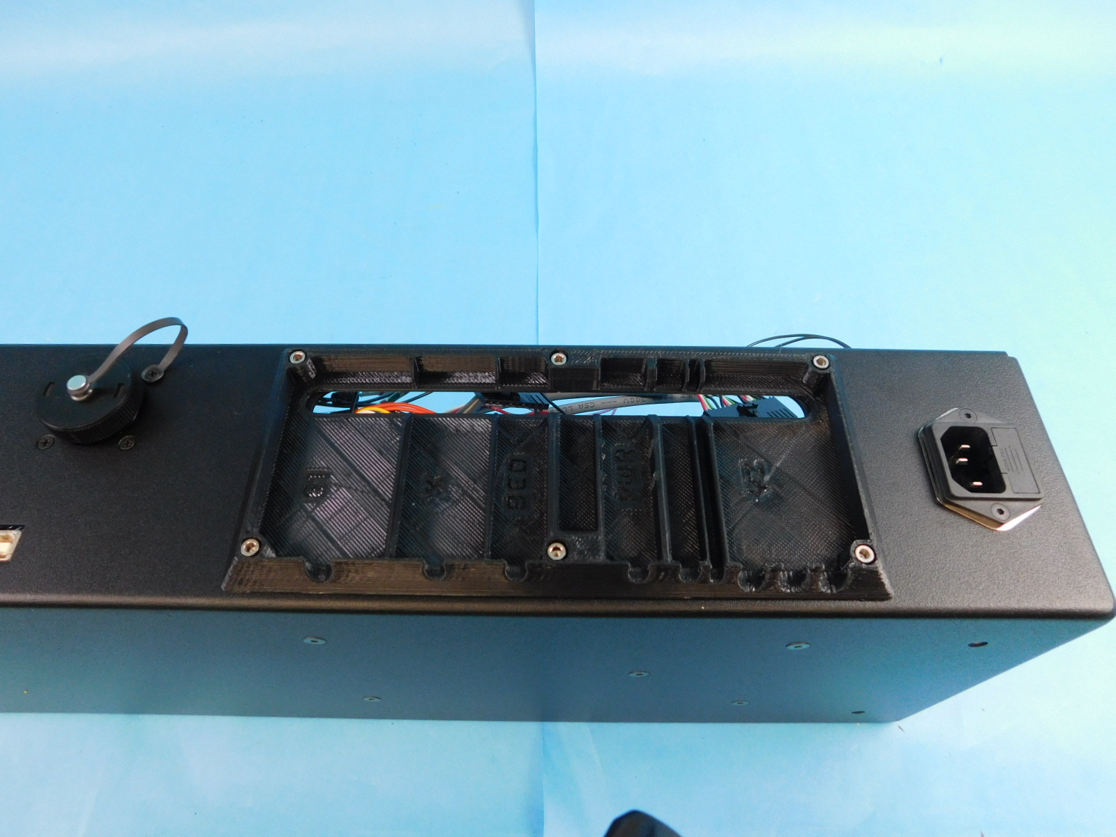
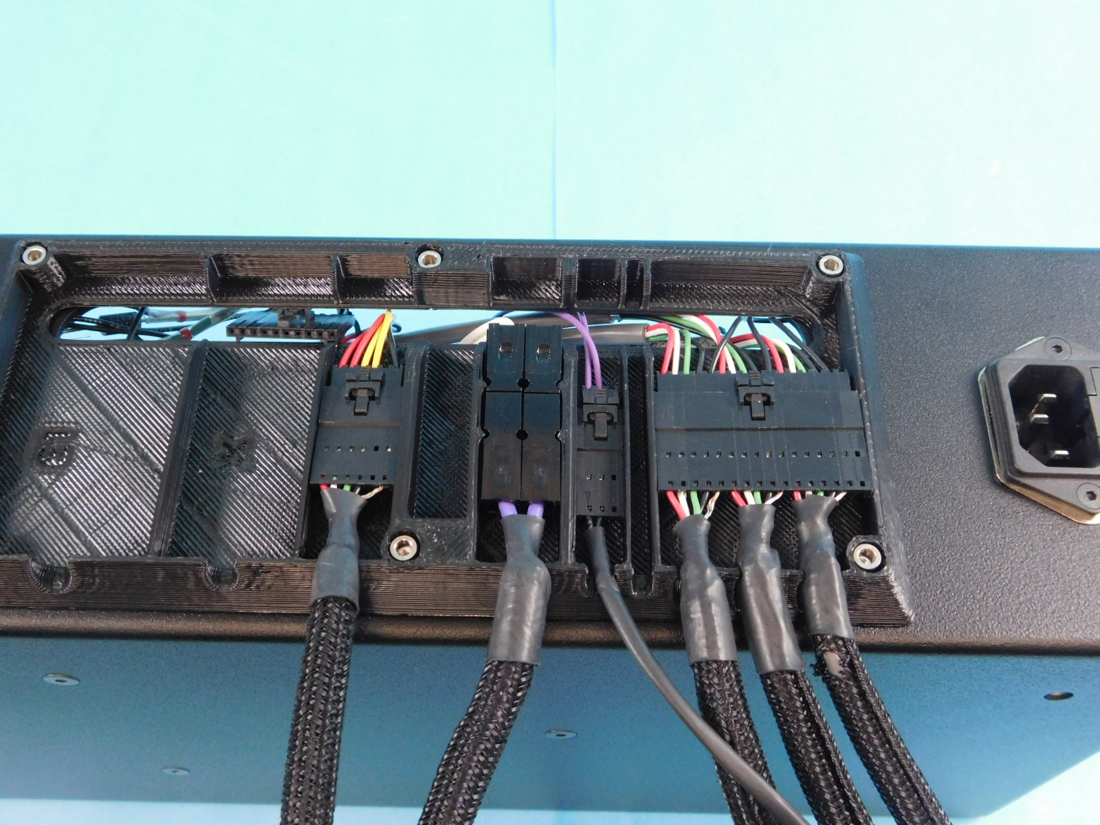
Flip the assembly so that the back of the chassis faces up
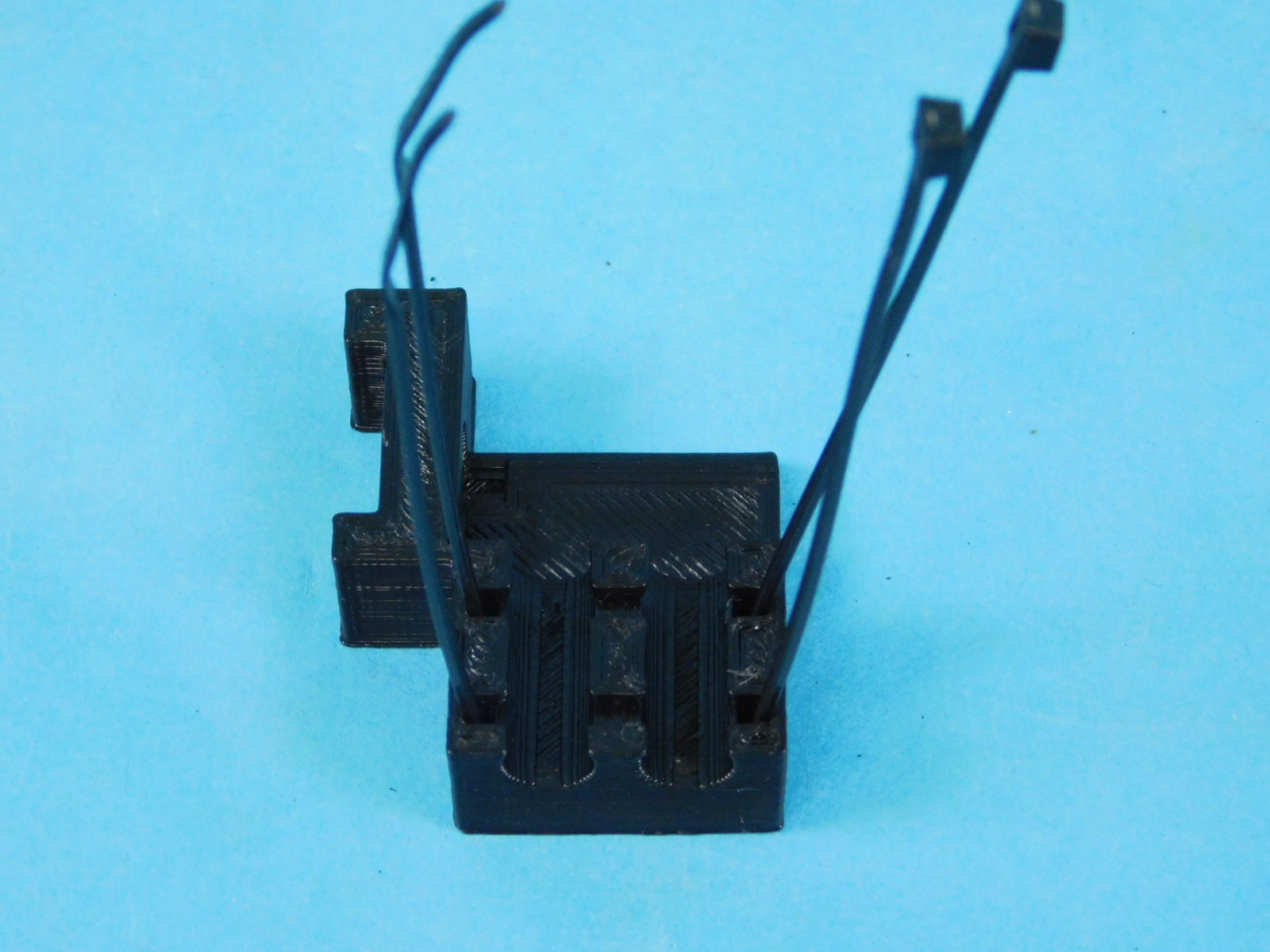
Obtain one Interconnect Housing [PP-GP0438]
Place it over the posts on the rear of the chassis with the slot in the printed part aligned with the slot in the chassis.
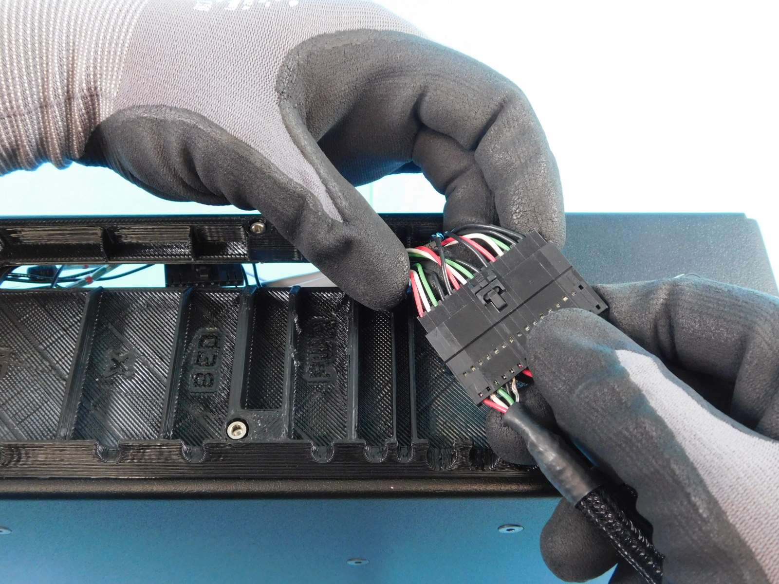
Obtain one Y/Z Harness, Assembled [EL-HR0181]
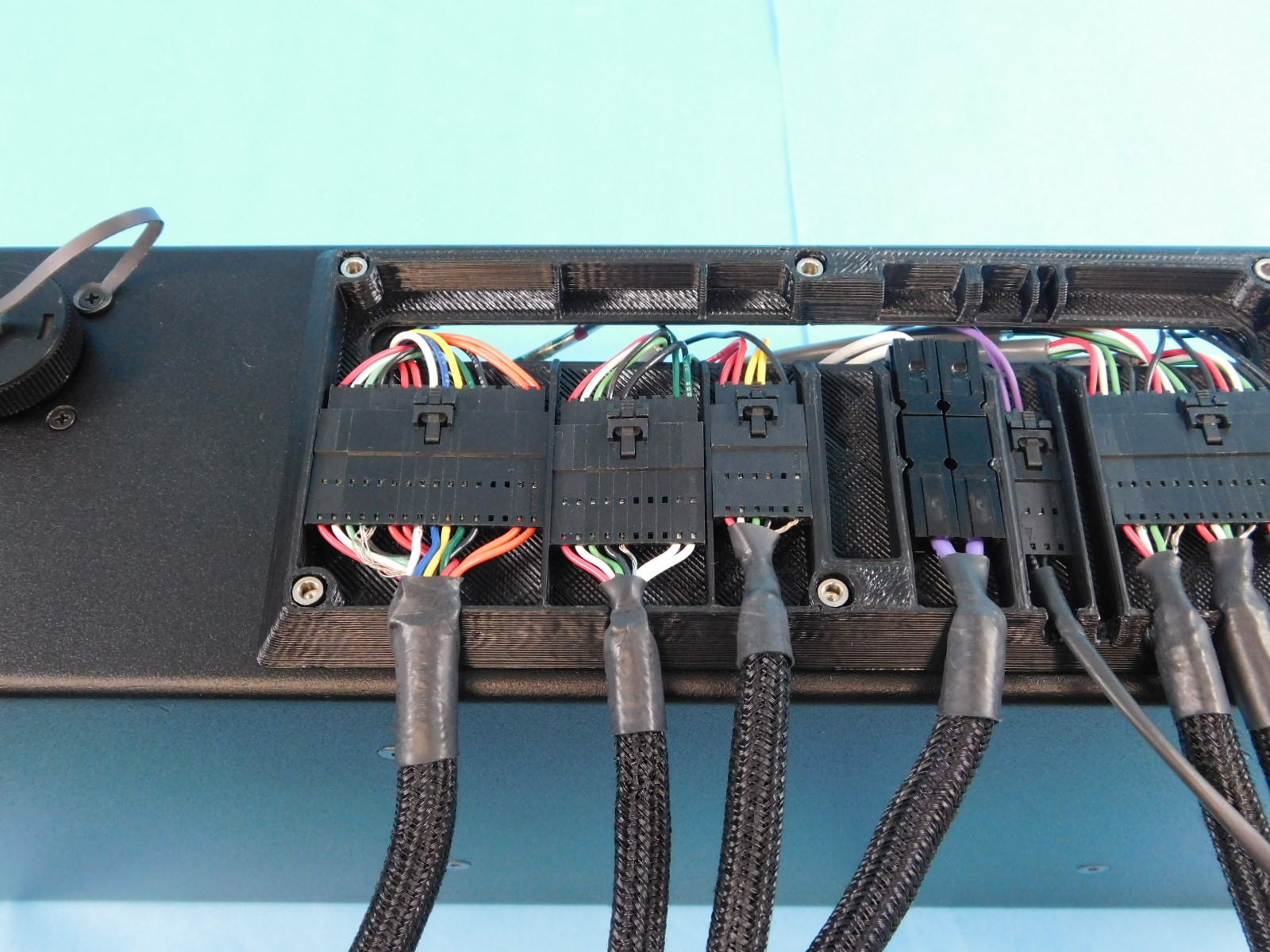
Pull the connector of the internal Y/Z Harness [EL-HR0183] through the slot in the rear of the chassis and connect the large connector of the external Y/Z Harness [EL-HR0181]
Pull the connector of the Y Endstop Harness [EL-HR0177] through the slot in the rear of the chassis and connect the 2 pin connector of the external Y/Z Harness [EL-HR0181]
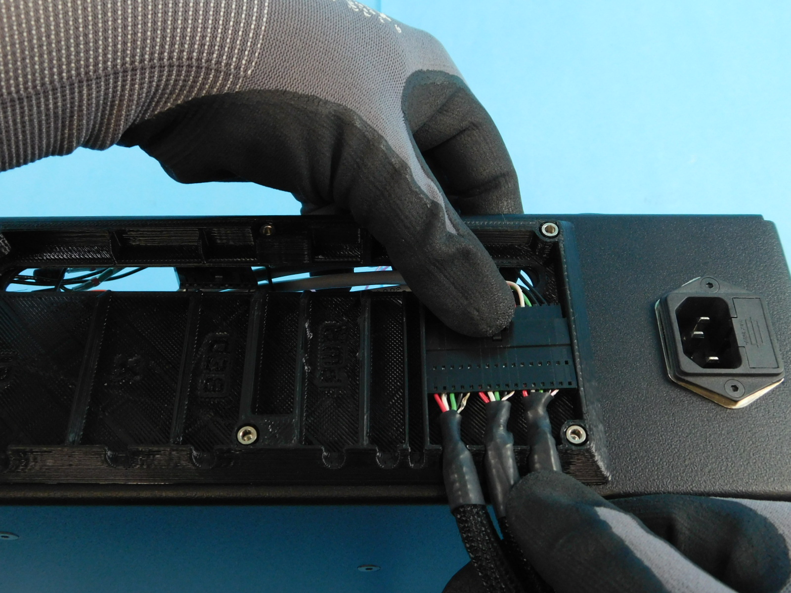
Push the connector into the wide slot in the Interconnect Housing [PP-GP0438] and carefully push the braided loom of all 3 leads into their respective slots.
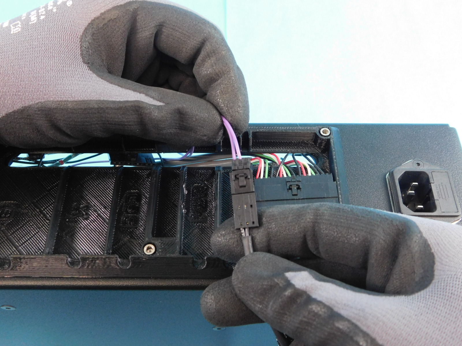
Place the Y Min Endstop lead through the smaller slot shown, 2nd from the Y/Z harness.
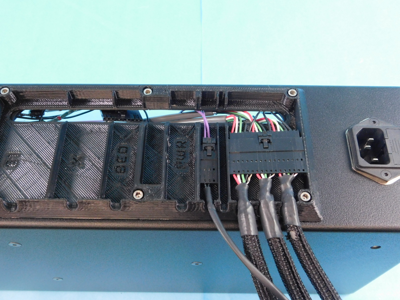
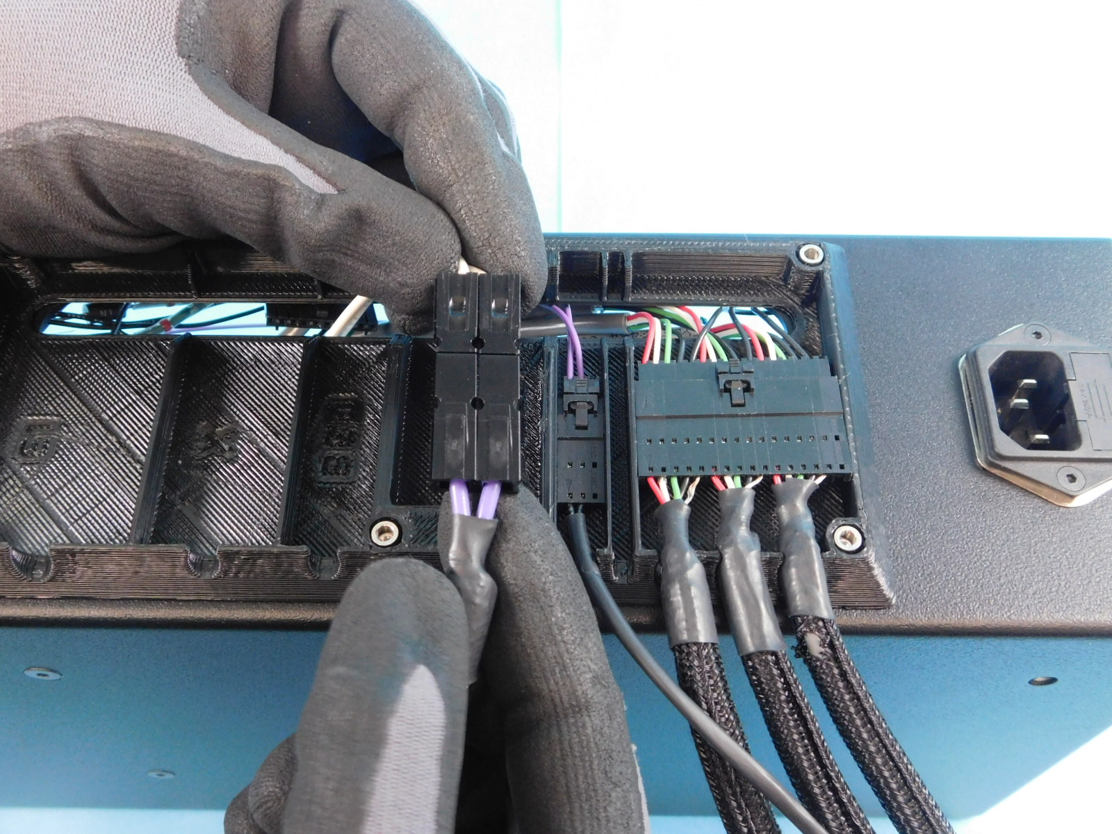
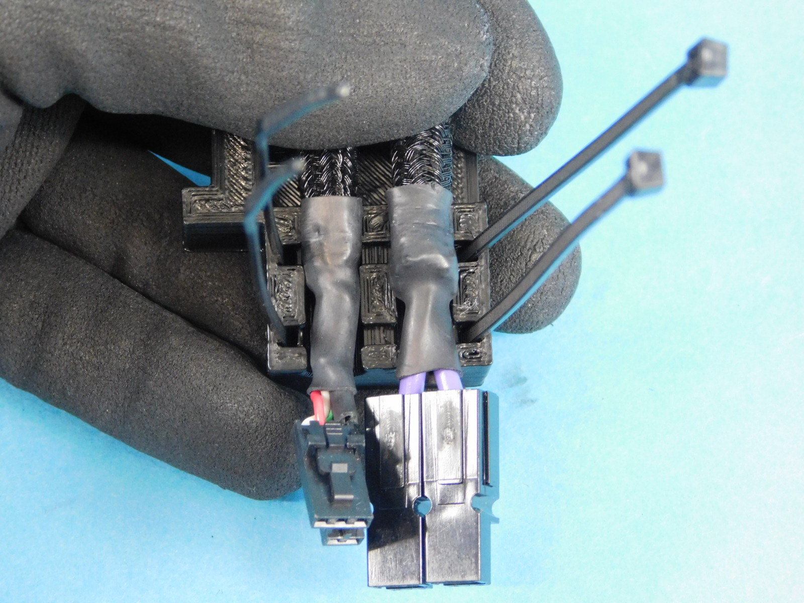
Obtain one Bed Power Harness [EL-HR0174]
Pull the CB Bed Power Harness [EL-HR0148] through the slot in the rear of the chassis.
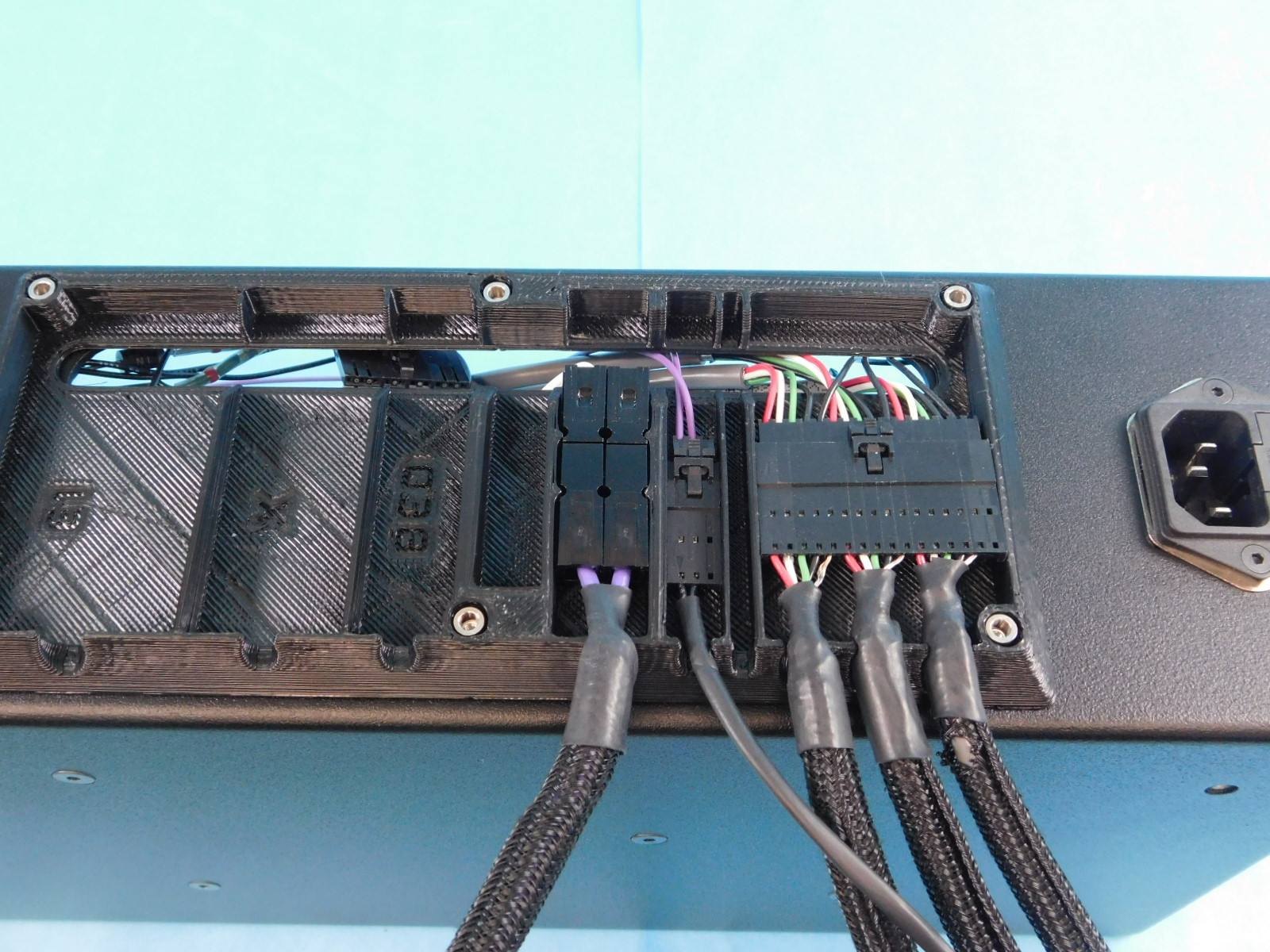
Connect the two Anderson connectors and press them into the retaining feature of the Interconnect Housing [PP-GP0438] as pictured.
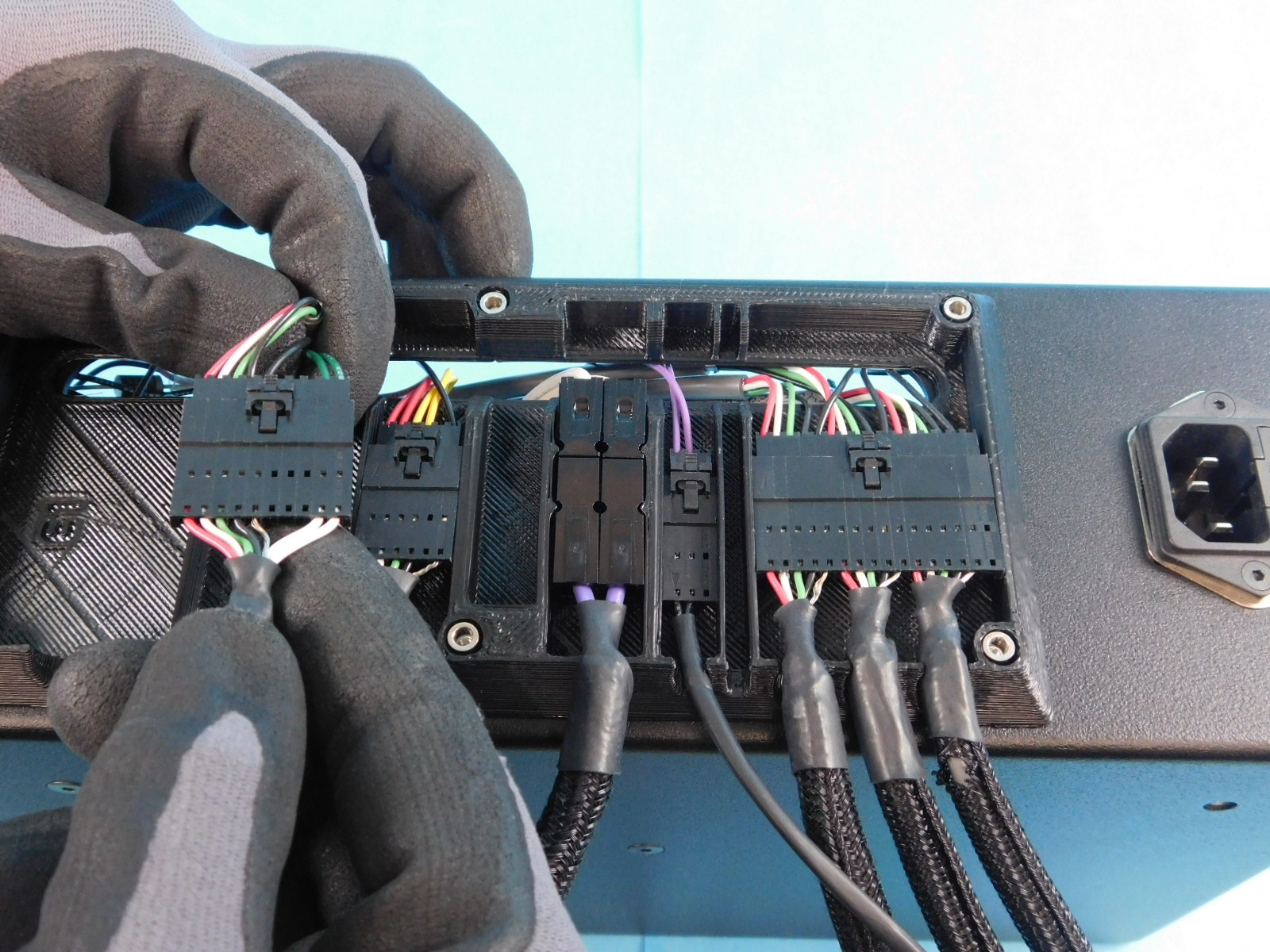
Obtain one Y Bed Harness [EL-HR0180]
Pull the CB Bed Harness [EL-HR0184] through the slot in the rear of the chassis and connect it to the Y Bed Harness [EL-HR0180]
Seat both connectors in the appropriate channels of the Interconnect Housing [PP-GP0438] as pictured.
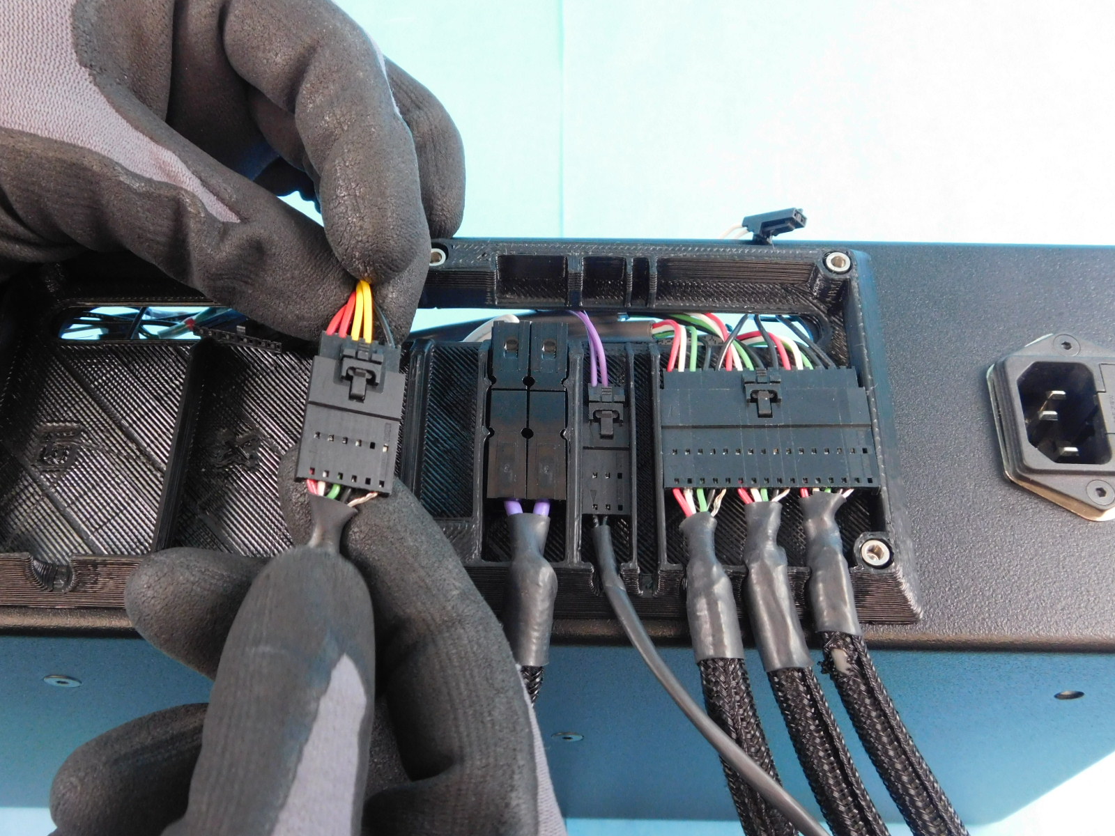
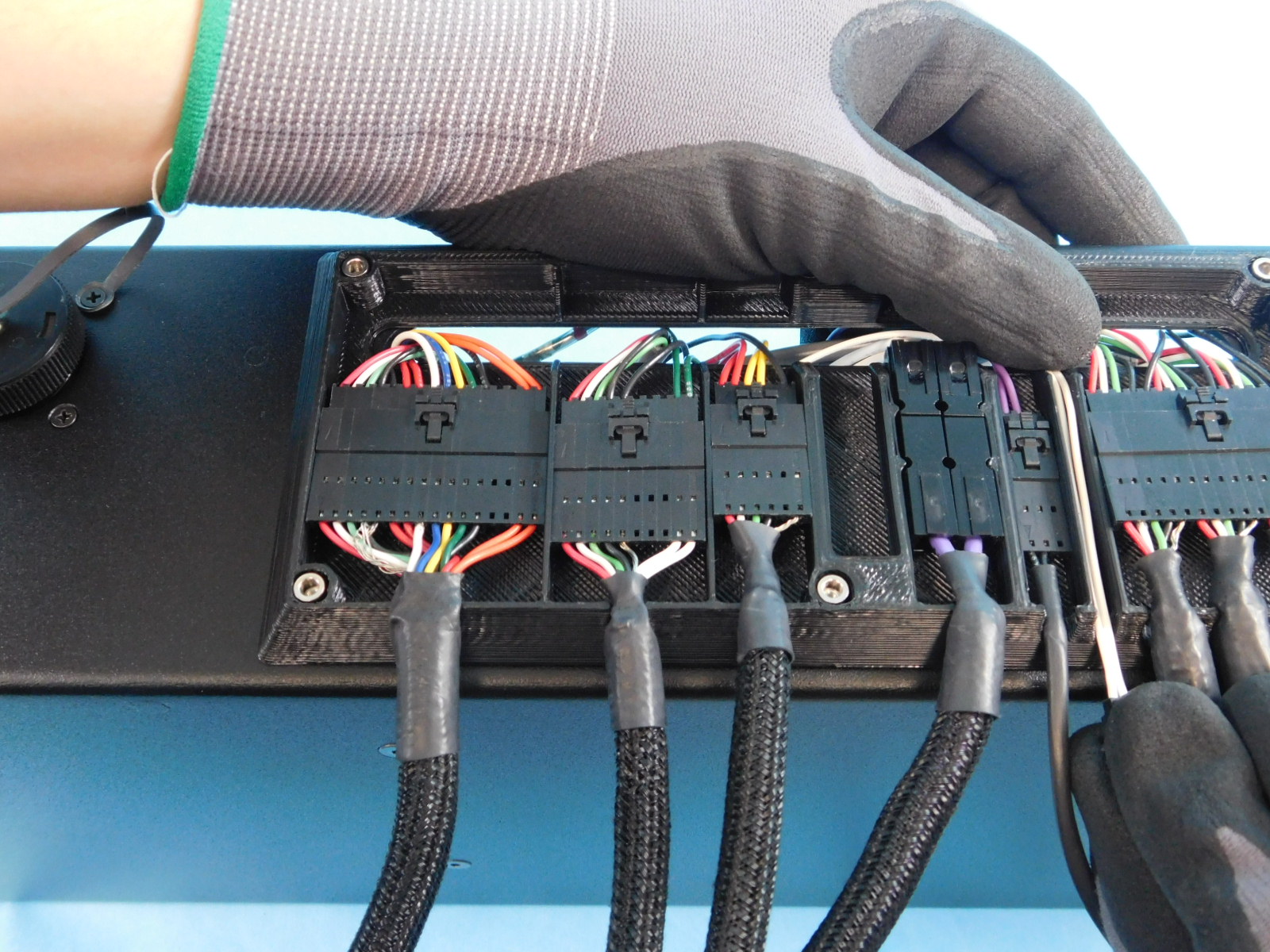
Obtain one X Harness [EL-HR0179]
Pull the CB X Harness [EL-HR0173] through the slot in the rear of the chassis.
Connect the 10 pin connector of the X Harness [EL-HR0179] to the CB X Harness [EL-HR0173]
Fit the loom carefully into the respective slot on the Interconnect Housing [PP-GP0438] as pictured.
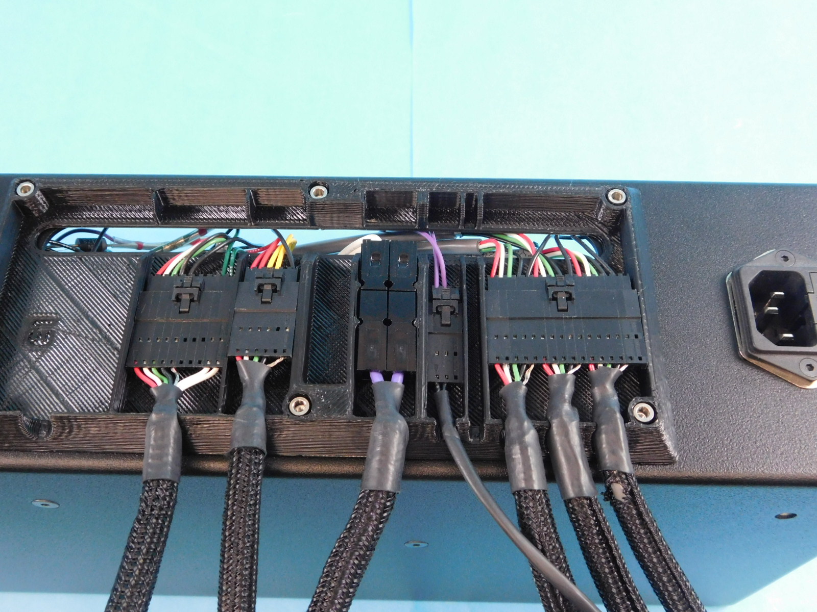
Obtain one Extruder Harness [EL-HR0178]
Pull the large connector of the CB Extruder Harness [EL-HR0175] through the slot in the rear of the chassis and connect it to the Extruder Harness [EL-HR0178]
Fit the connector and the cable looms into the respective slots on the Interconnect Housing [PP-GP0438] as pictured.
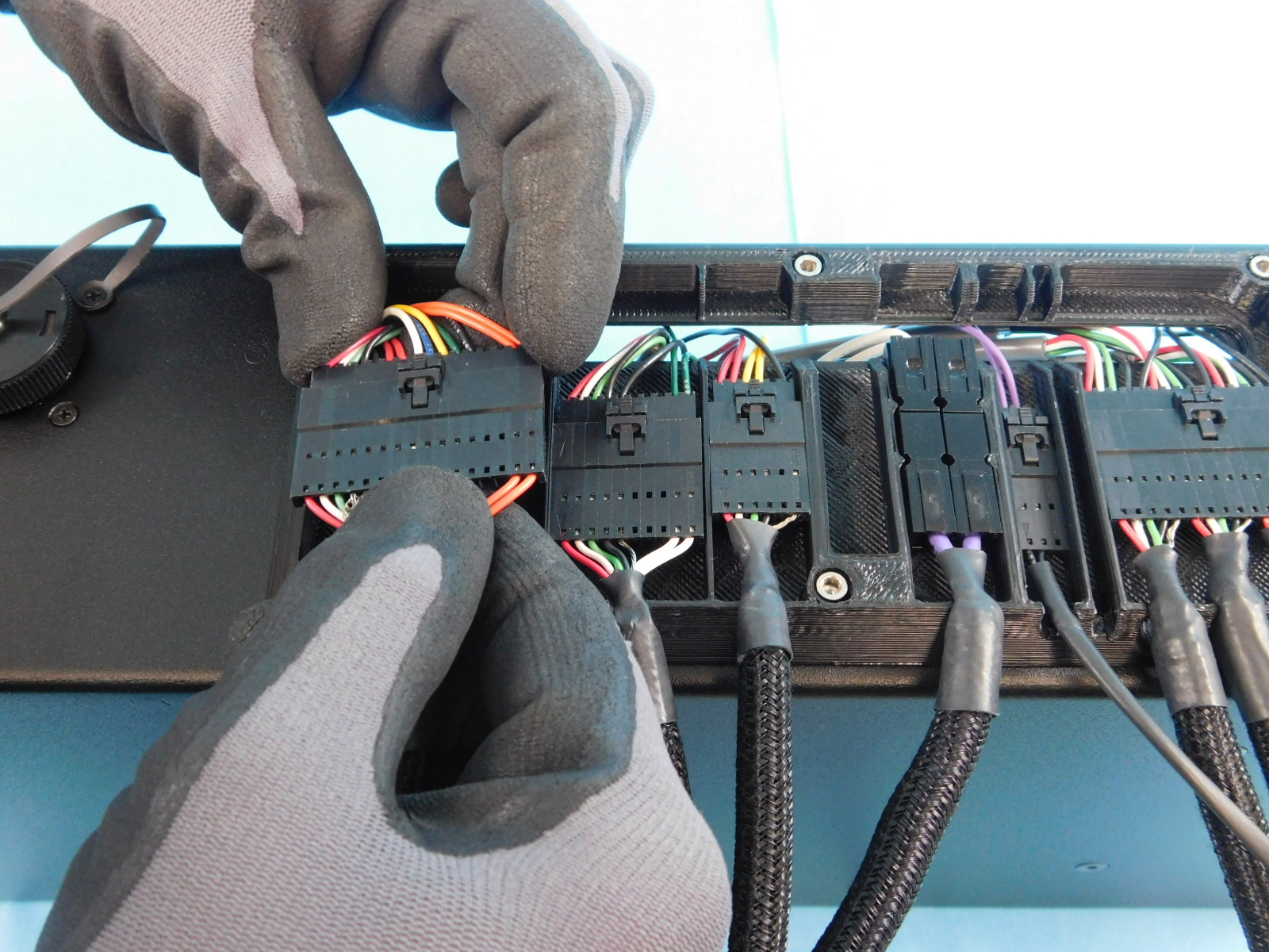
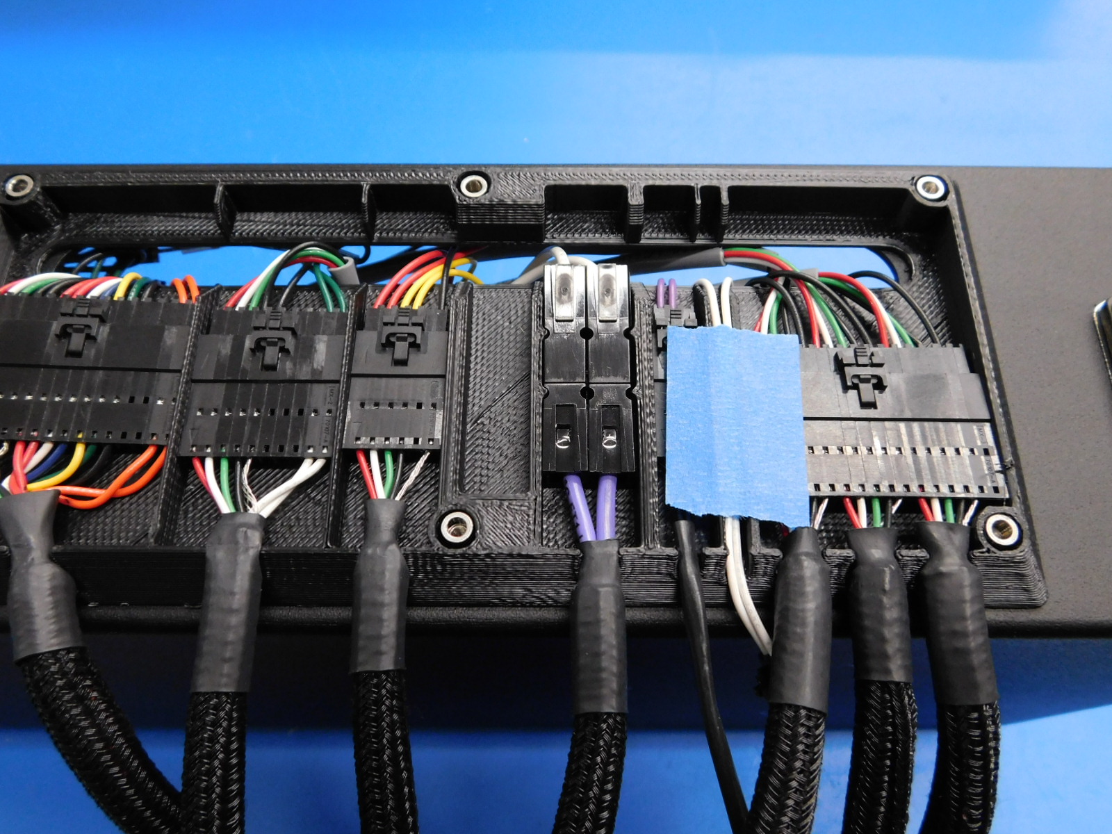
Obtain one Interconnect Housing Cover [PP-FP0153]
Pull the 2 pin connector of the CB Z Endstop Harness [EL-HR0185] through the slot in the rear of the chassis and lay it in the channel as pictured.
Use a ~1" piece of blue painters tape to hold the Z-Endstop Harness in the slot and ensure it isn't pinched while installing the cover.
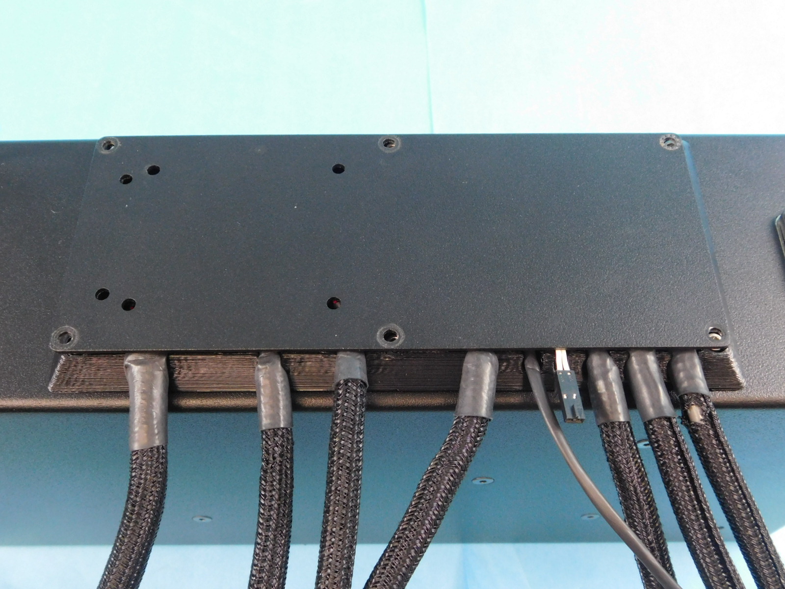
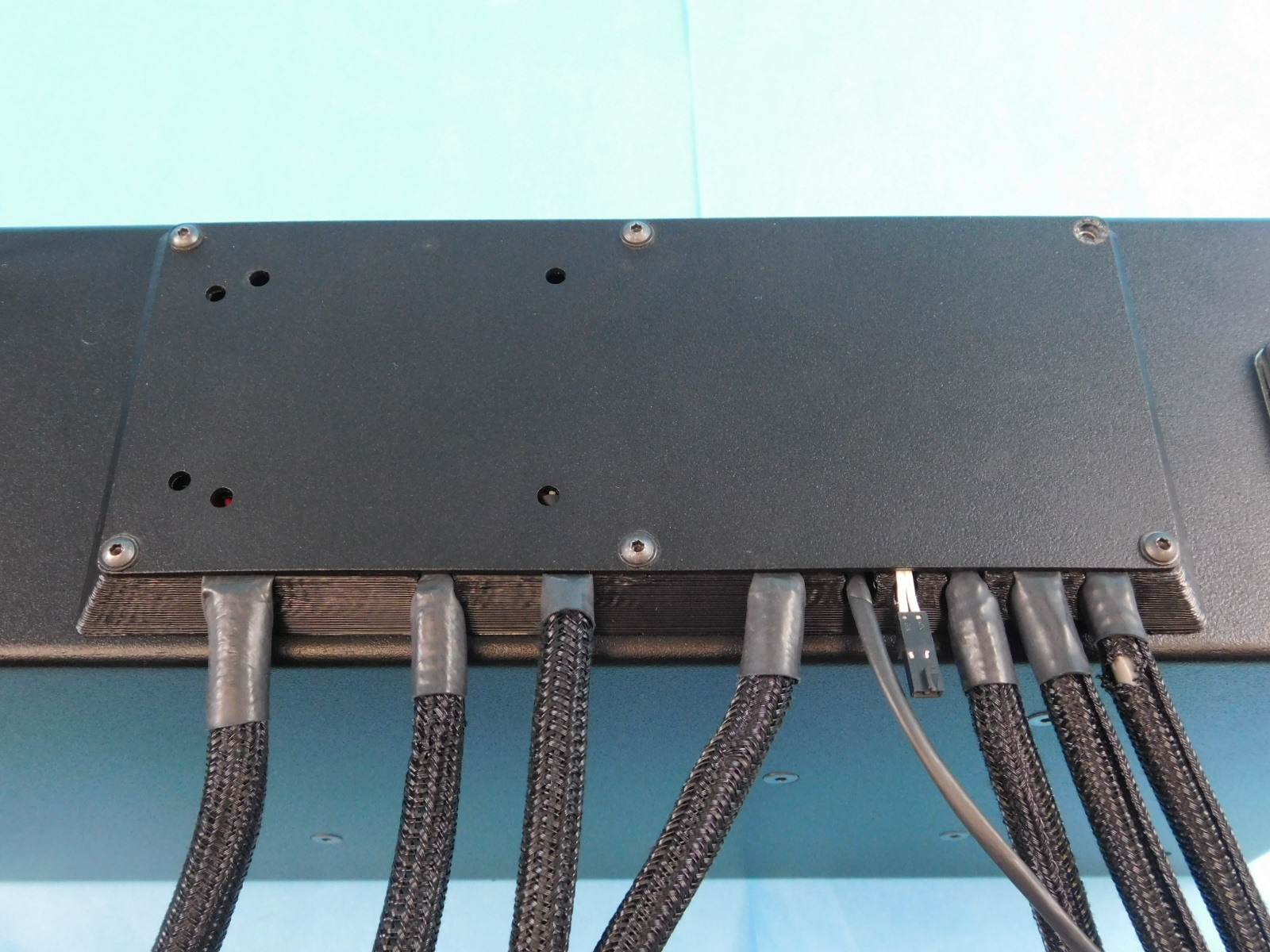
Place the Interconnect Cover [PP-FP0153] over the cables with the extra holes towards the top.
Ensure no wires are pinched, pay special attention to the Z Max Wires and Y Min Endstop Wires
Secure the Interconnect Cover [PP-FP0153] using five (5) M3x8 BHCS [HD-BT0137] with washers [HD-WA0038] at the highlighted locations.
Torque to 5in-lbs
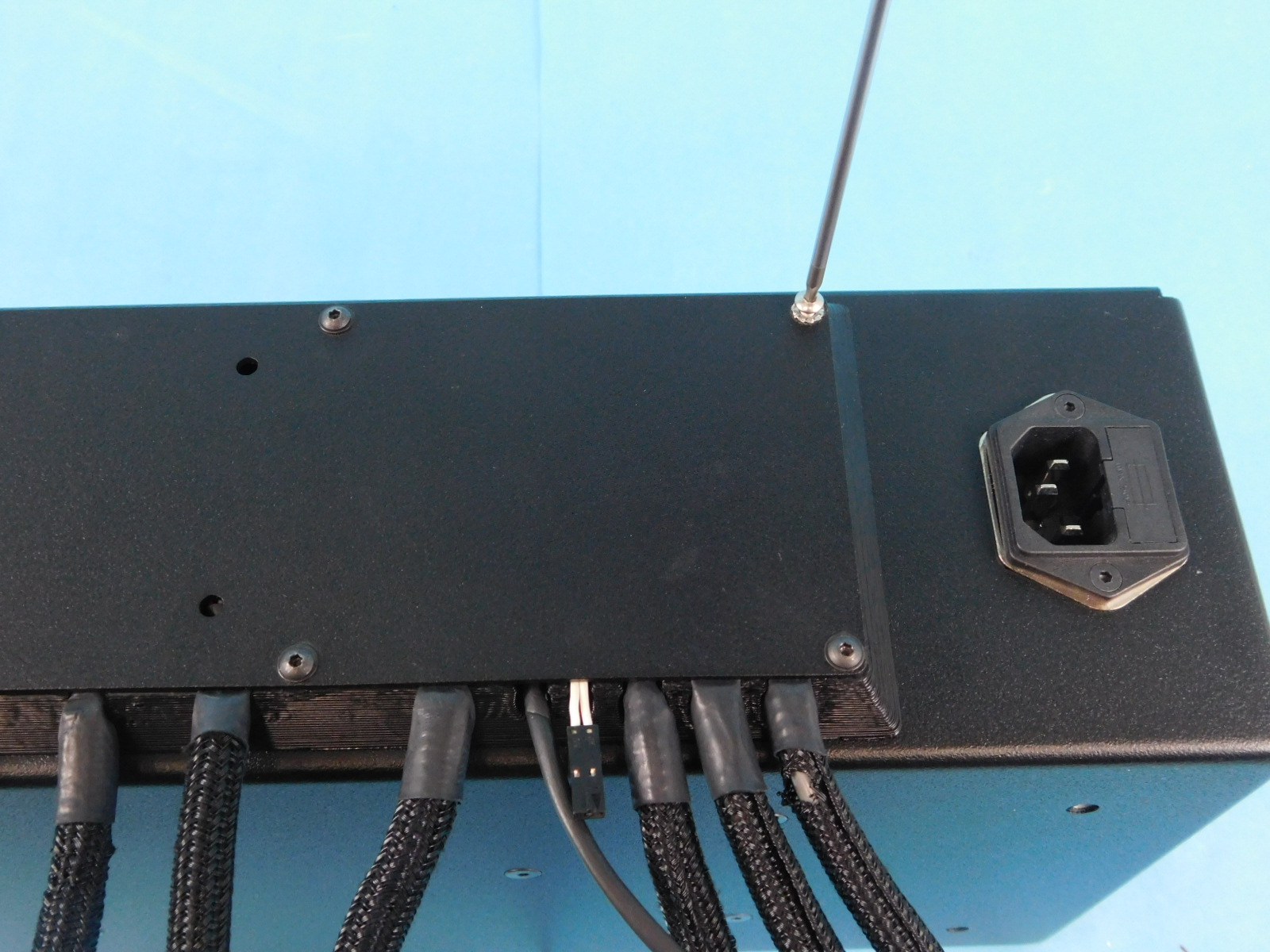
Use one (1) M3x10 Stainless BHCS [HD-BT0234] and one Serrated Lock Washer [HD-WA0035] at the location highlighted.
Torque to 5in-lbs
Obtain one Electronics Cover [PP-FP0164]
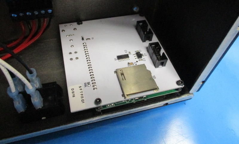
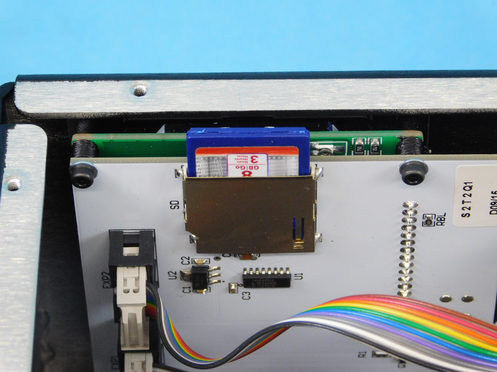
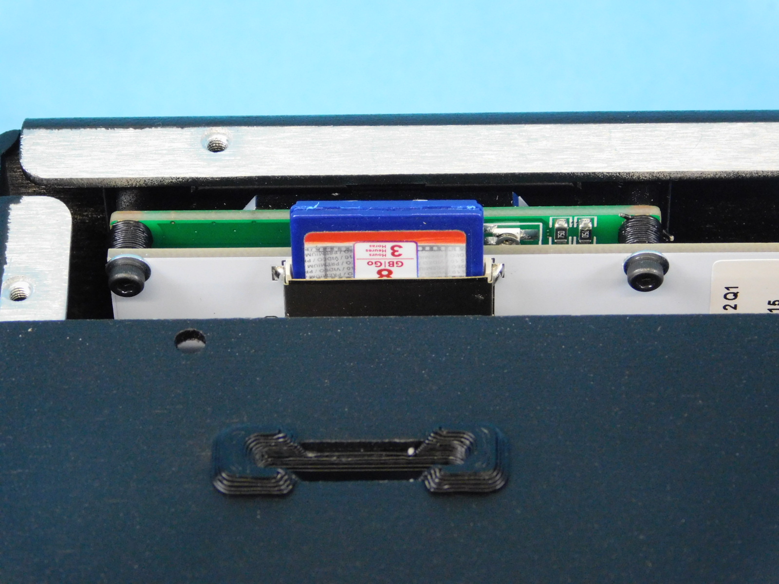
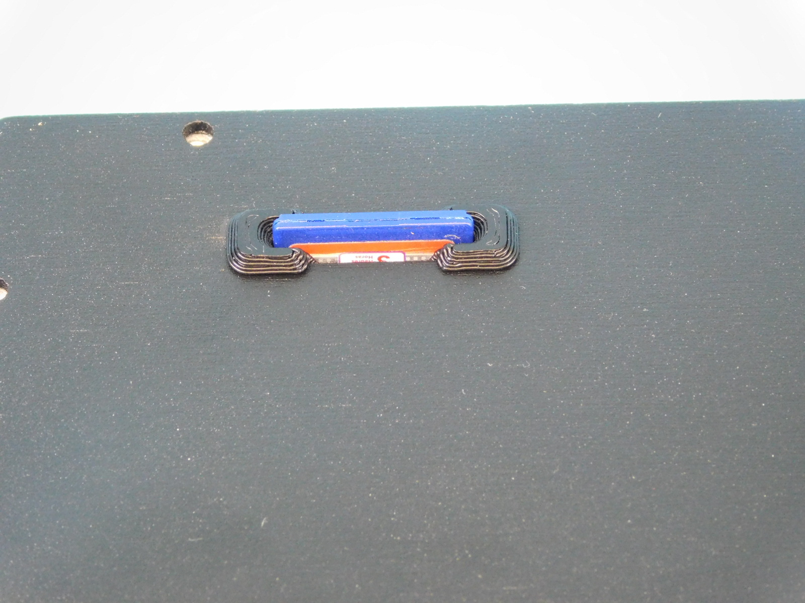
Place an SD card in the SD Card slot on the LCD as pictured.
Press one SD Card Bezel [PP-GP0235] into the slot on the Electronics Cover [PP-FP0164]
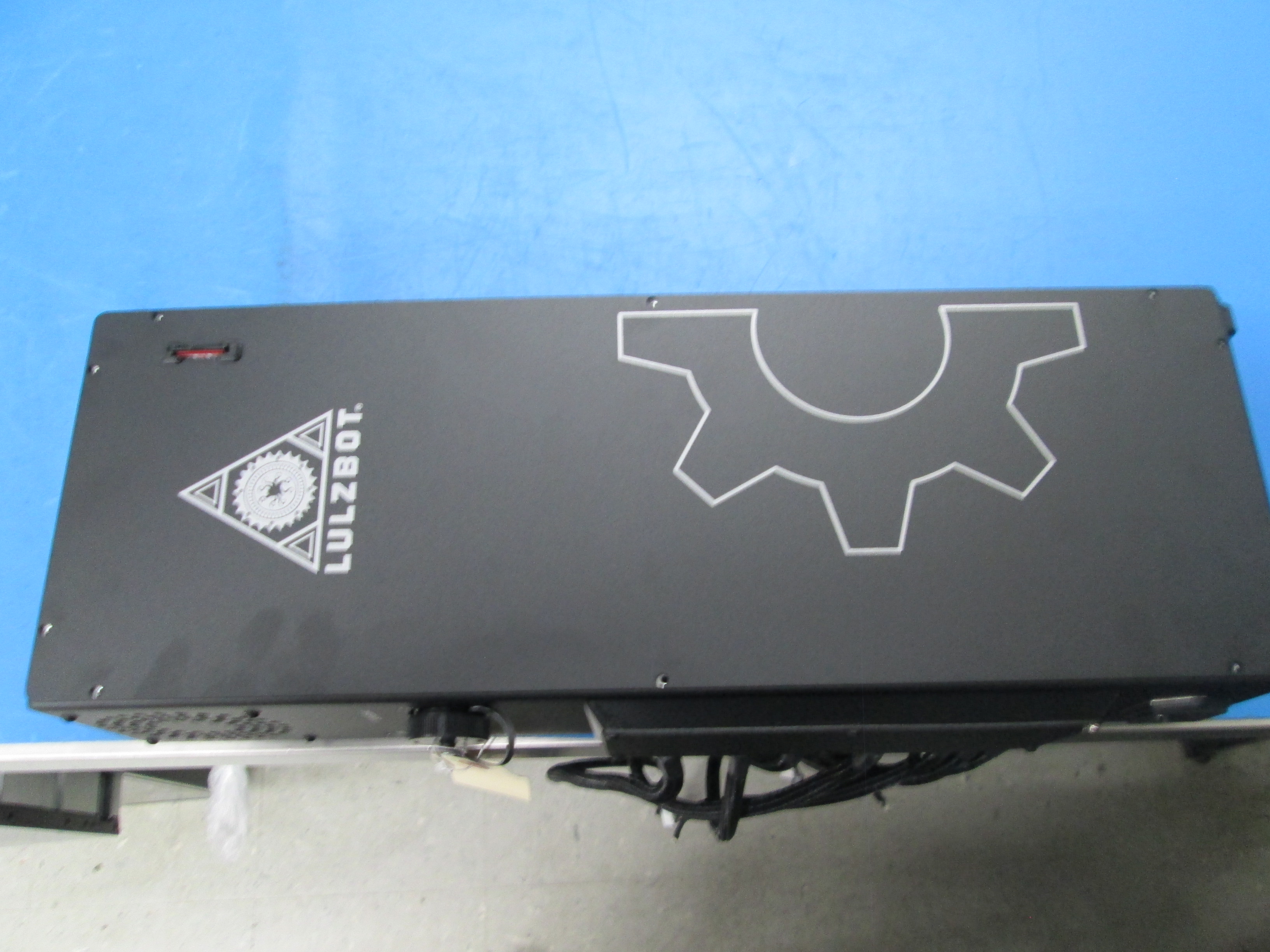
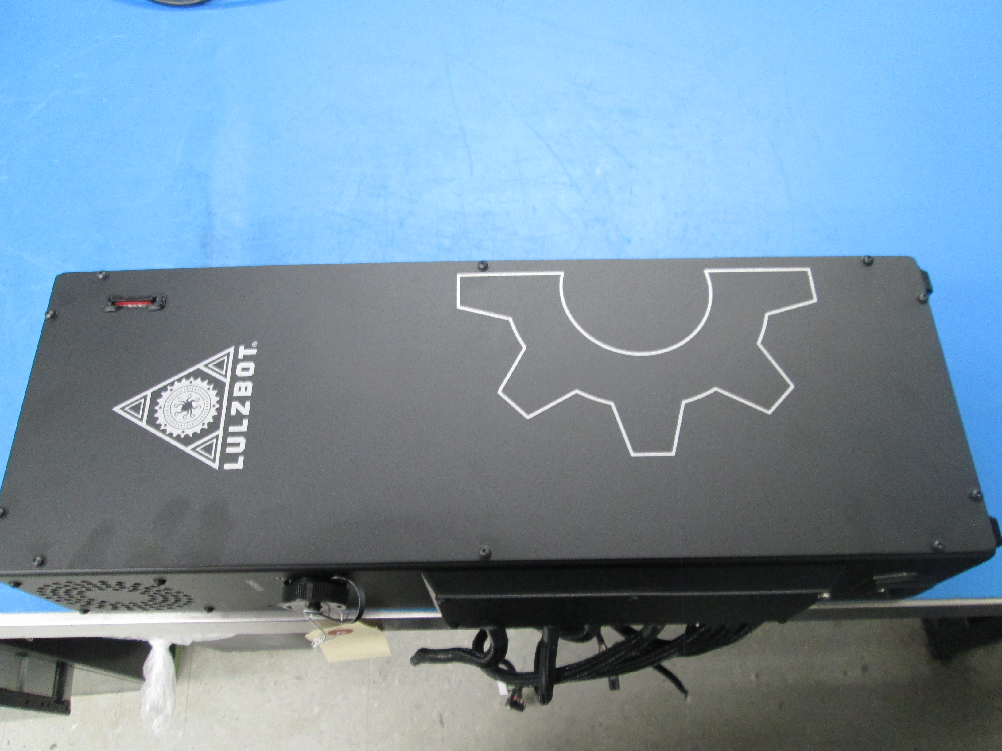
Place the Electronics Cover [PP-FP0164] on the chassis with the LulzBot logo towards the top of the chassis.
Ensure the SD card slot is properly aligned
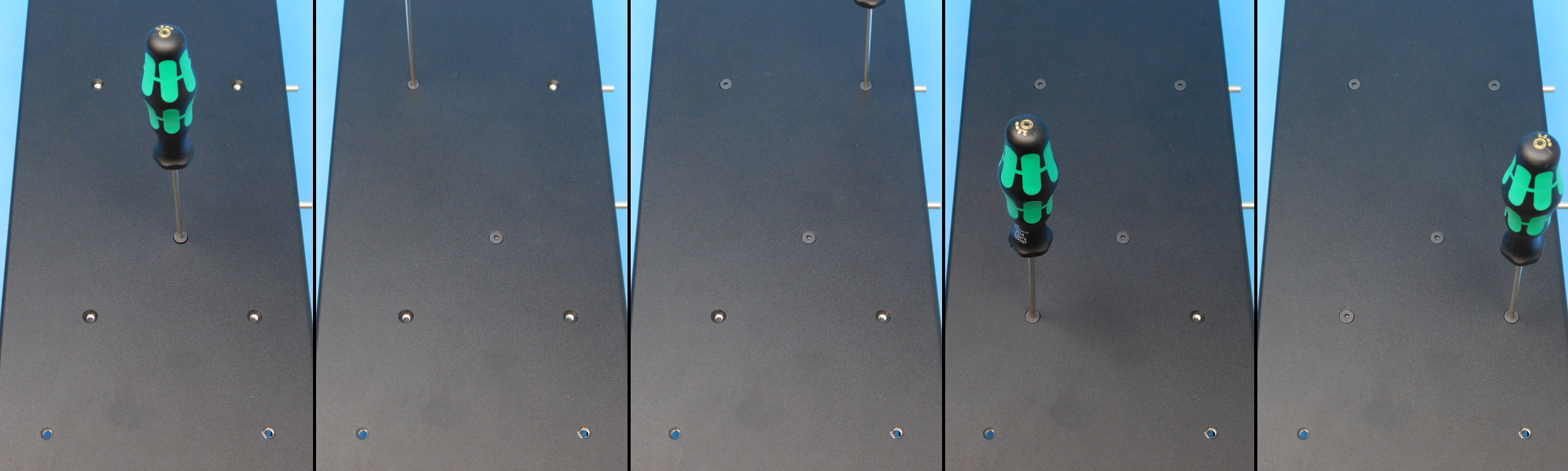
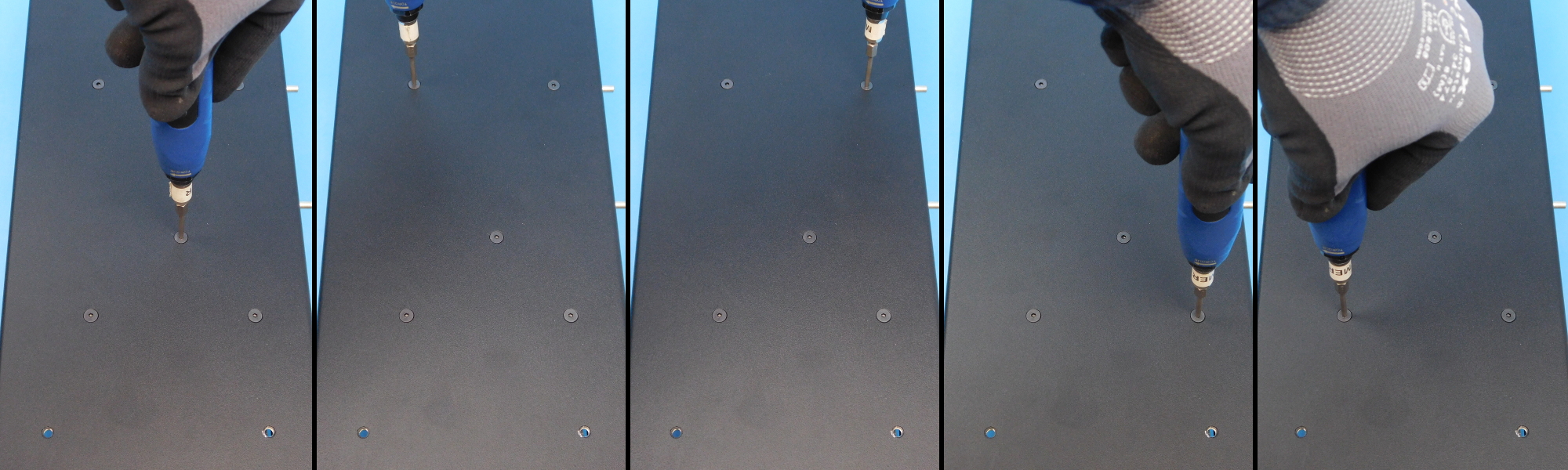
Secure using ten (10) M3x6 BHCS [HD-BT0140] with washers [HD-WA0038]
Install fasteners using your red power driver on the lowest setting (~5in*lbs)
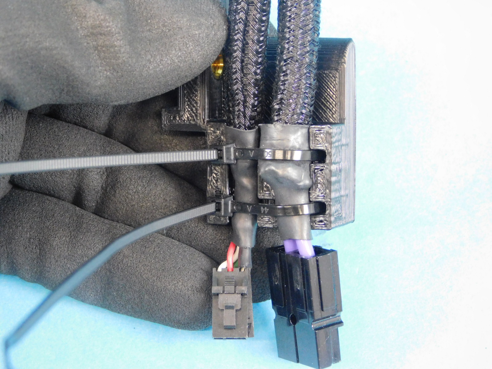
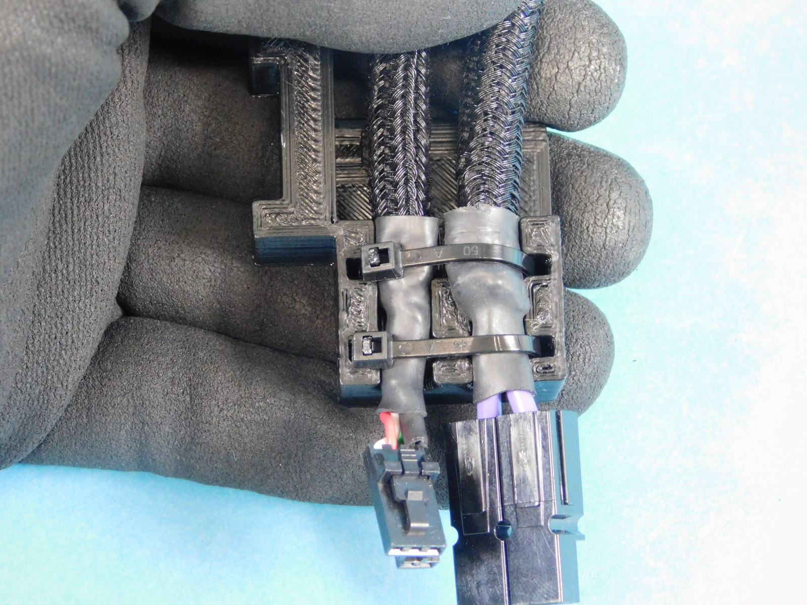
Obtain one Y Cable Mount with Insert [PP-IS0116]
Attach it to the Bed Harness and Bed Power Harness as pictured using two zip-ties [HD-MS0058]
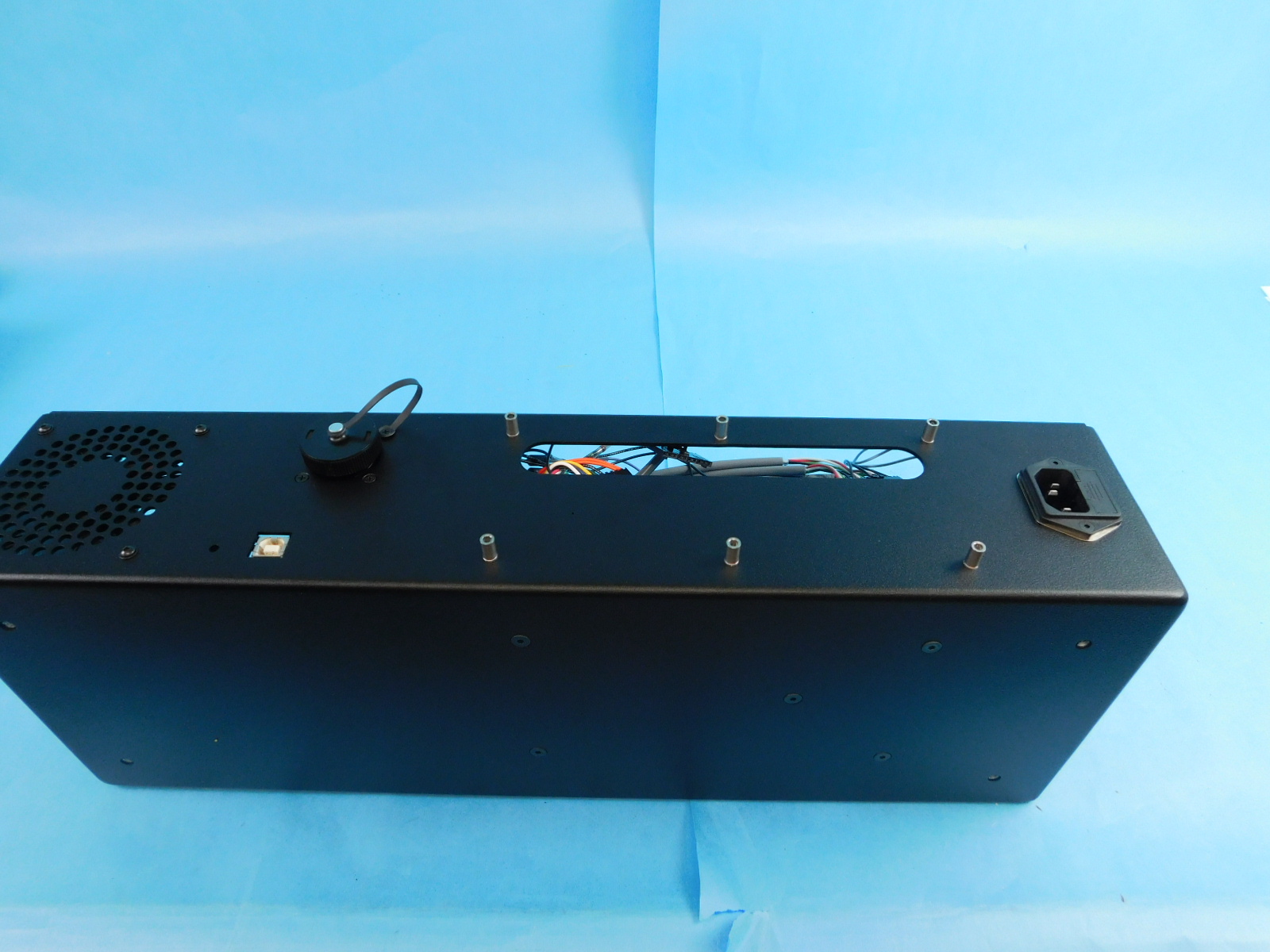
Now that the Control Box is fully assembled, proceed to Control Box Testing