Open HardwareAssembly Instructions
Guides for installation and assembly of the LulzBot line of products made by Aleph Objects, Inc.
Guides for installation and assembly of the LulzBot line of products made by Aleph Objects, Inc.
Materials Required for :
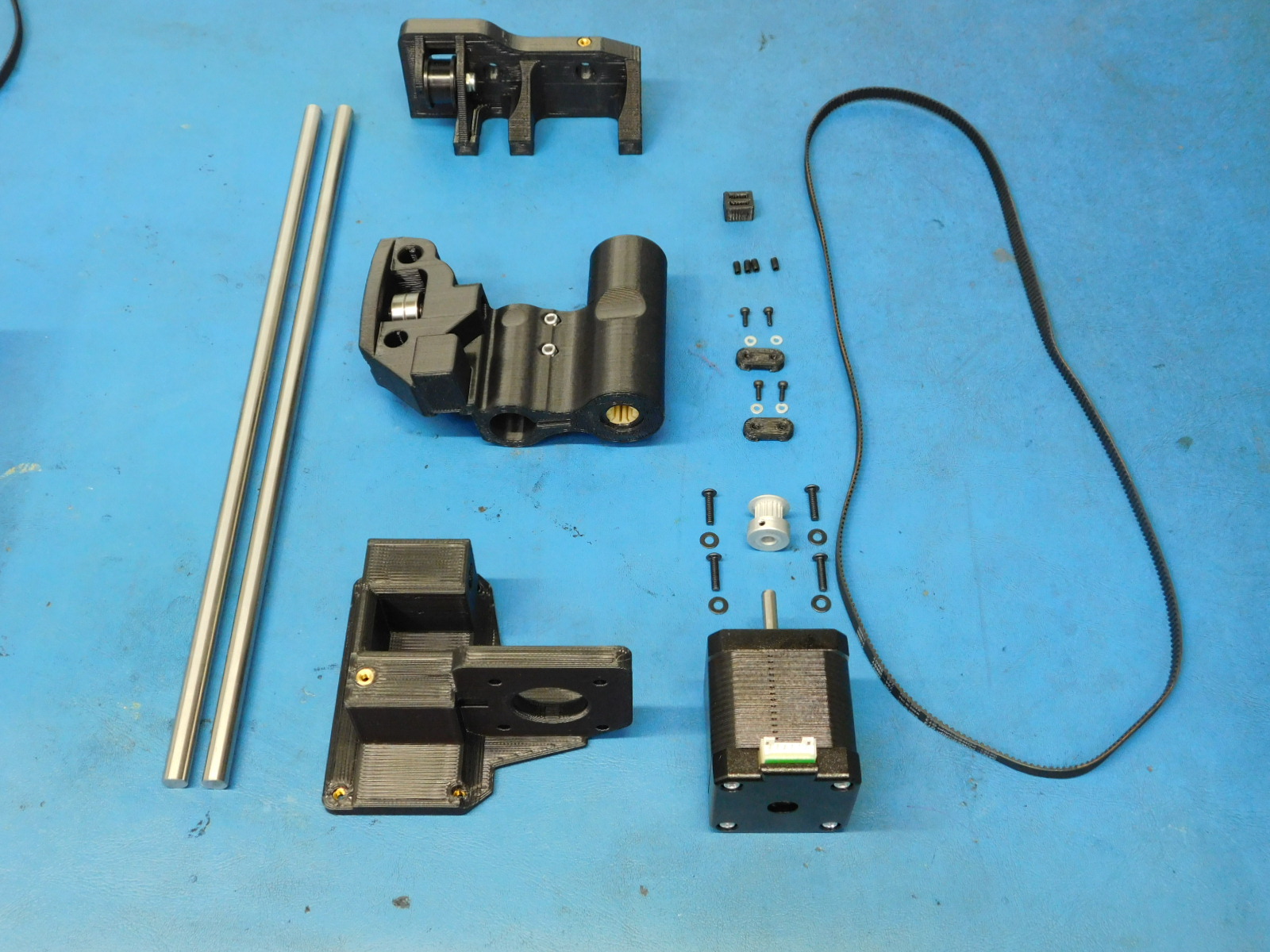
1x- [AS-PR0087] X End Idler Assembly With Inserts and Bushings, Mini 2
1x- [AS-PR0088] Z Upper Right Assembly, Mini 2
1x- [PP-GP0307] Belt Tensioning Collar
2x- [PP-GP0308] Z Belt Clamp
1x- [] Z-Lower Right w/ inserts, Mini 2
1x- [EL-MT0029] NEMA 17 Stepper Motor, Moons' - NOT INCLUDING wire harness
2x- [HD-BT0012] M3 Set Screw (Grub Screw)
1x- [HD-BL0033] Timing belt, 372 teeth, GT2 2mm pitch, 744 mm pitch length, 6 mm belt width, Neoprene
4x- [HD-BT0146] M3 x 12 BHCS, Black Oxide, Class 10.9 Steel
1x- [HD-MS0033] GT2, 16 Teeth, timing pulley, AL
4x- [HD-MS0230] Socket Head Cap Screw, Alloy Steel, M2 Thread, 6mm Length
4x- [HD-WA0012] Steel Flat Washer, M2 screw size
4x- [HD-WA0038] Black-Oxide Steel Flat Washer, M3 Screw Size
a) Using an 8mm part reaming tool, ream the 8mm smooth rod hole on the Z-Lower printed part [PP-IS0125] that has the M3 insert by turning the reamer clockwise in the hole. Be careful to NOT remove to much material causing the smooth rods to sit loose.
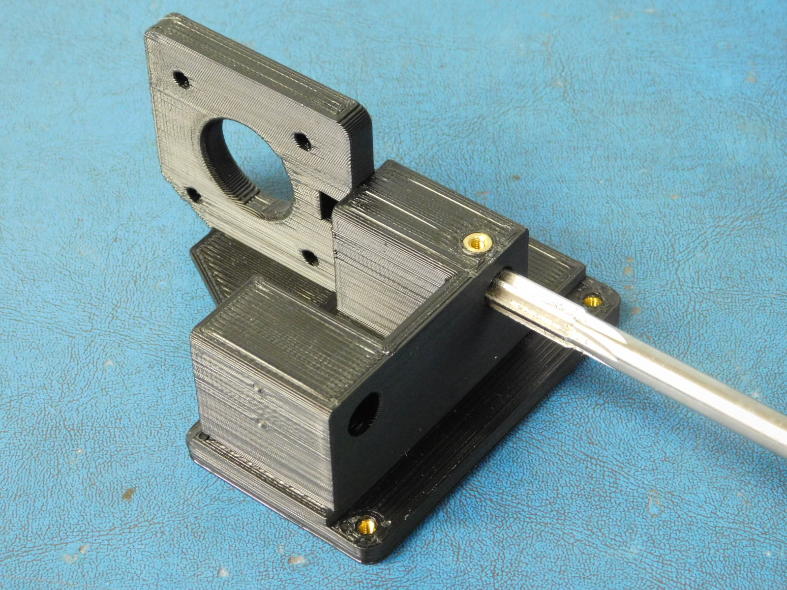
b) Insert a set screw [HD-BT0012] into the designated place on the z-lower right.
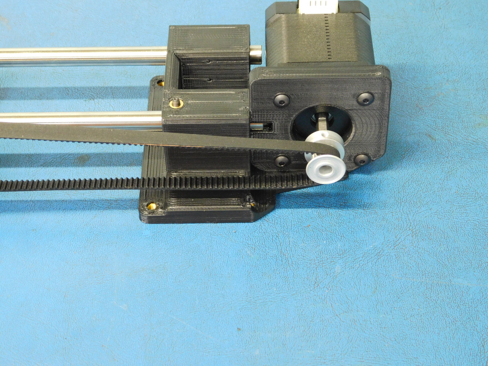
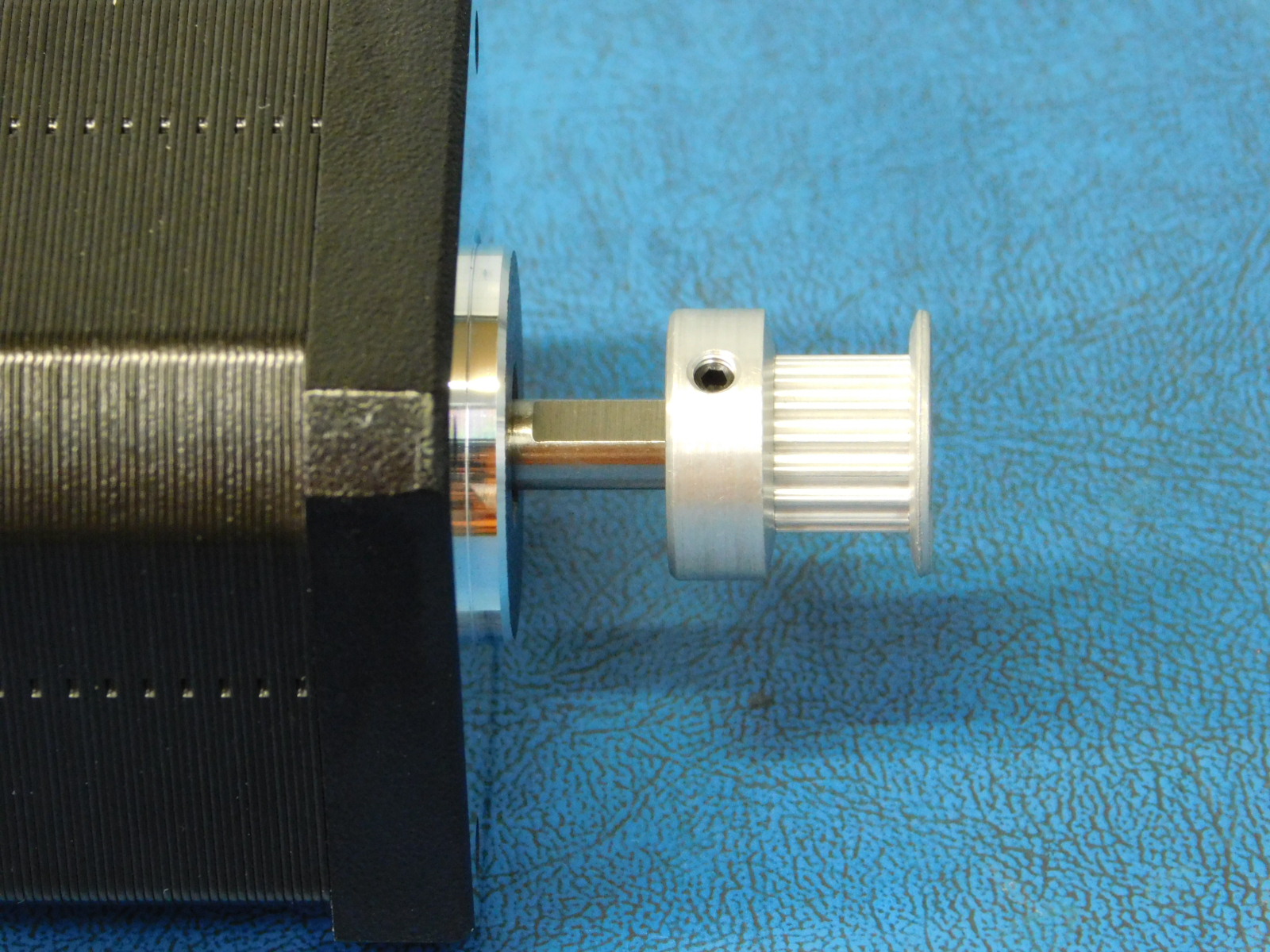
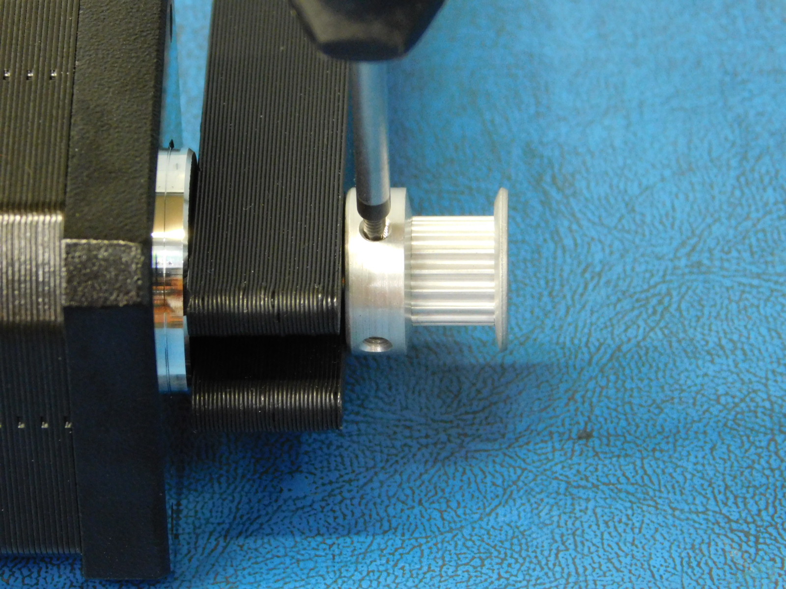
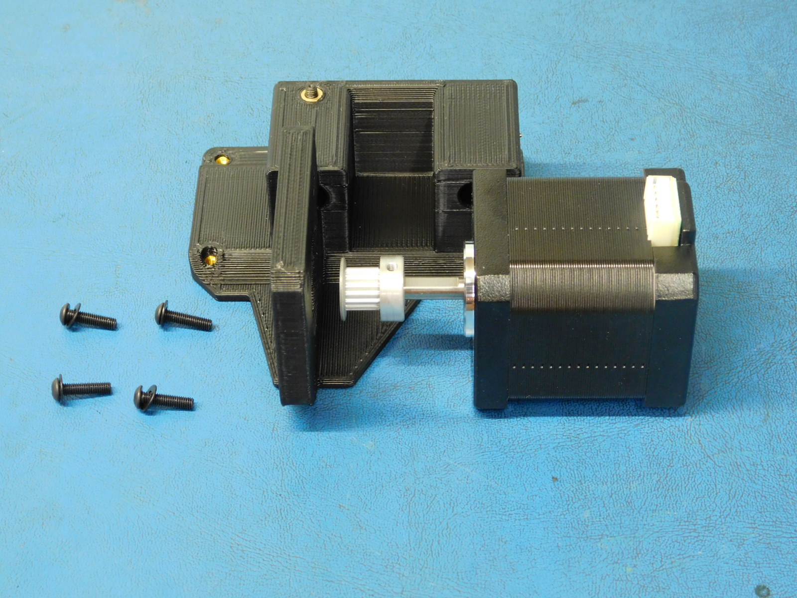
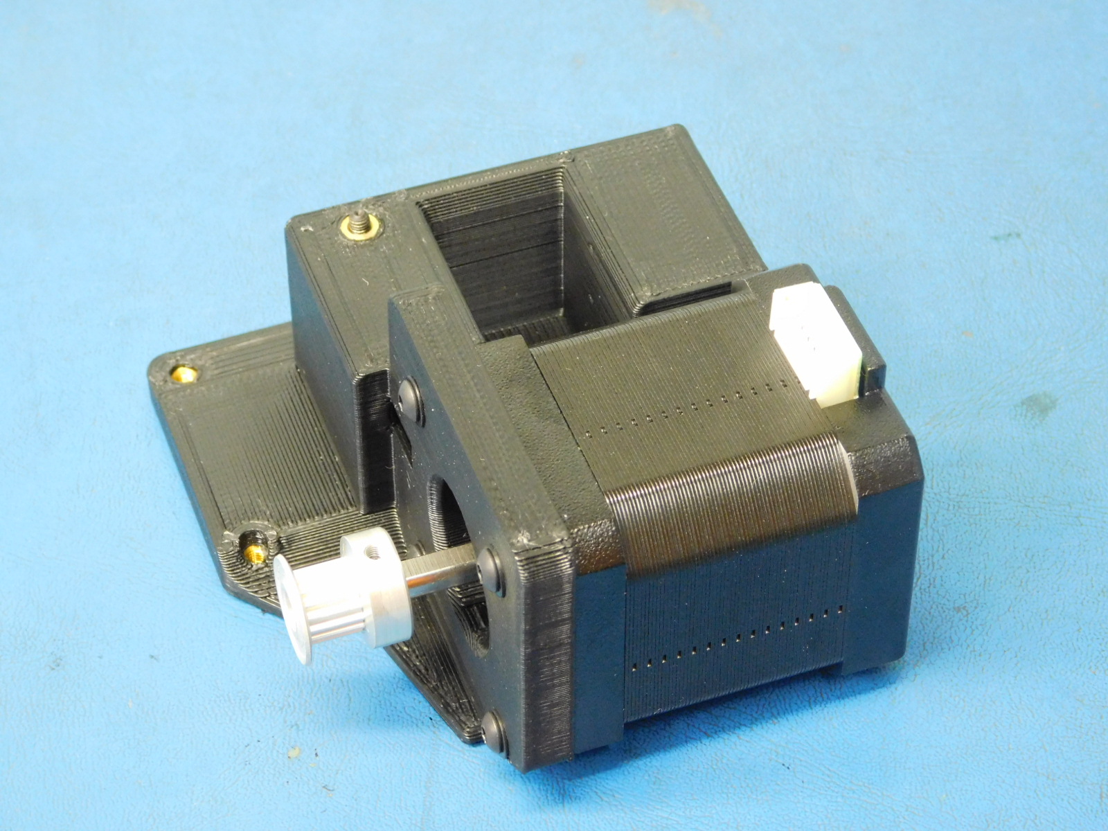
c) Attach a Pulley [HD-MS0033] to a Motor [EL-MT0029] offset the pulley from the face of the motor 13mm. Use the printed jig to ensure consistency. Ensure one of the pulley set screws is aligned with the flat segment of the motor shaft and the other set screw is position on the left side of the motor and tighten securely.
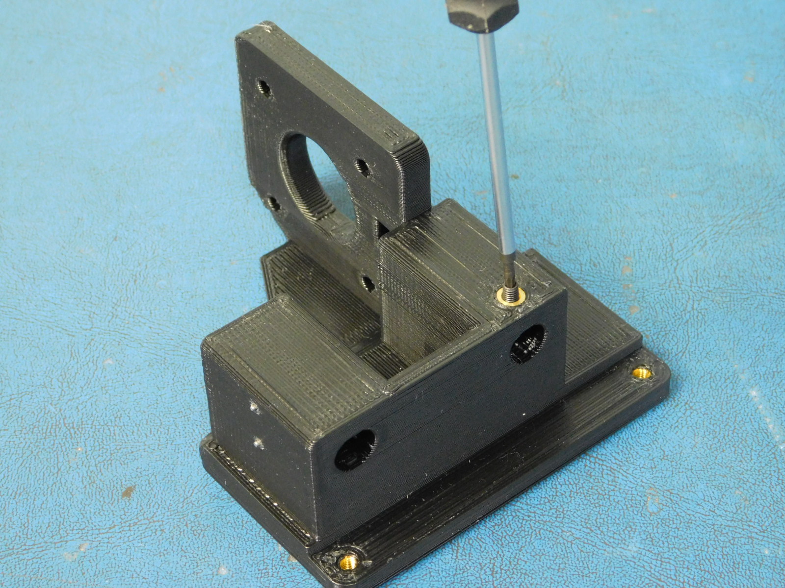
c) Secure the motor to the z-lower right with 4x- M3x12 BHCS [HD-BT0146] with 4x- M3 washers [HD-WA0038] , tighten screws to 8 in*lbs.
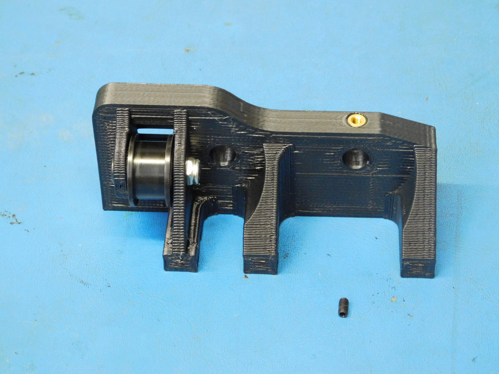
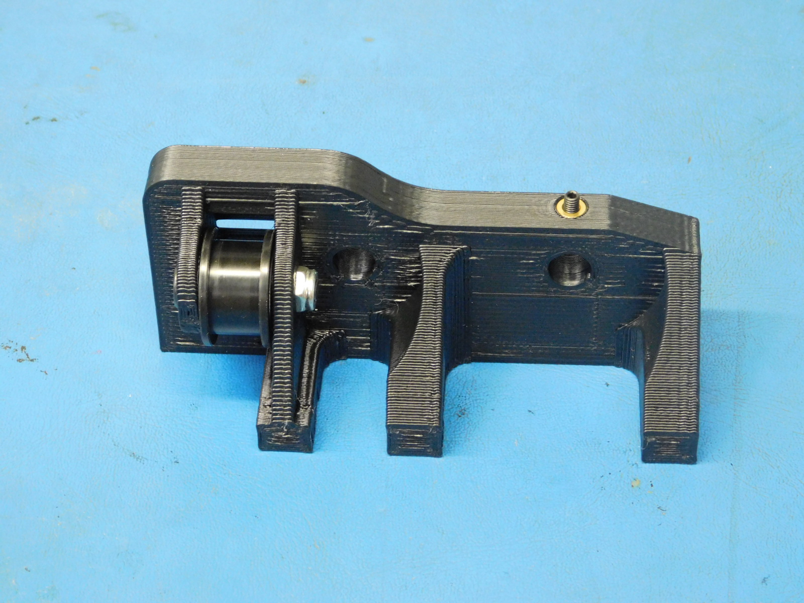
d) Insert a set screw [HD-BT0012] into the z-upper right [AS-PR0088].
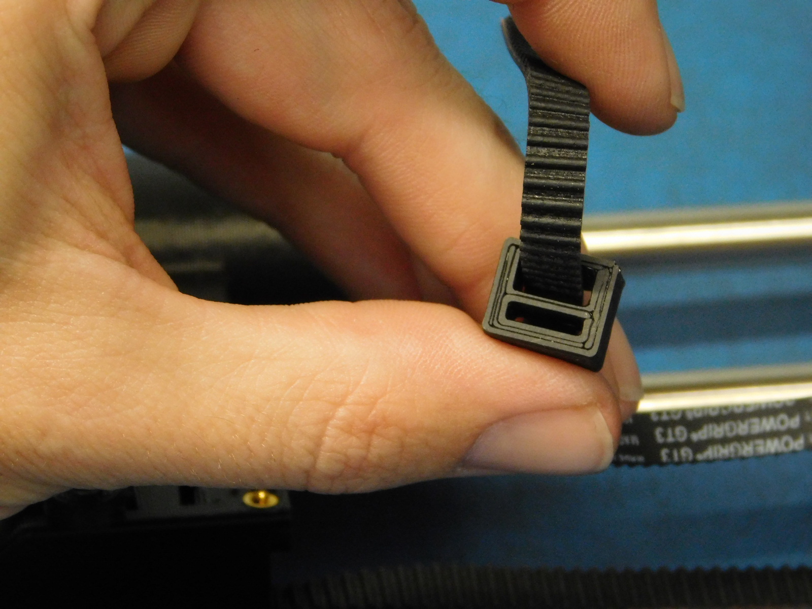
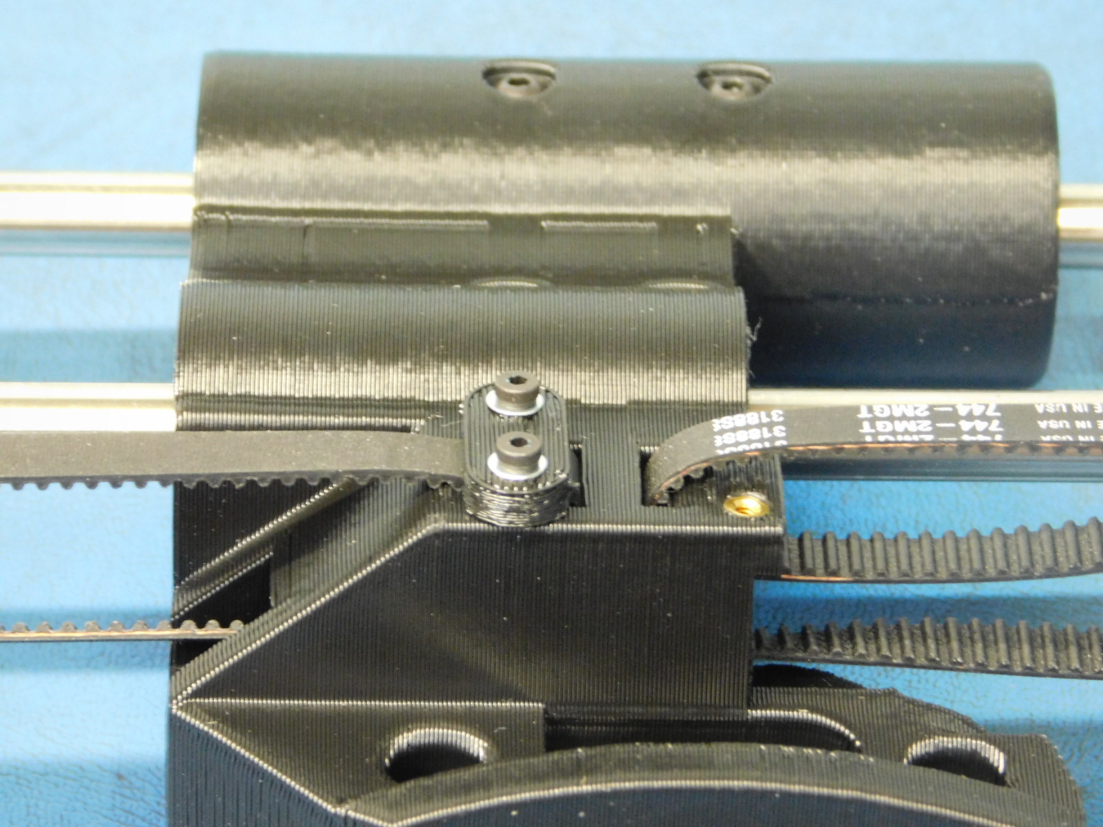
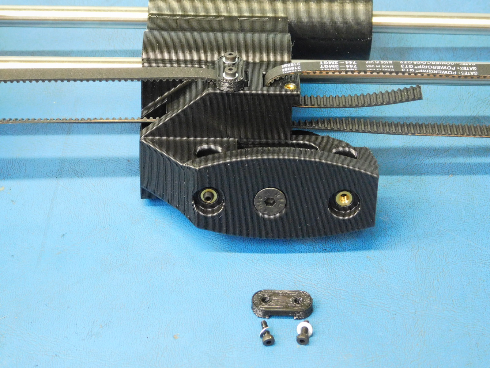
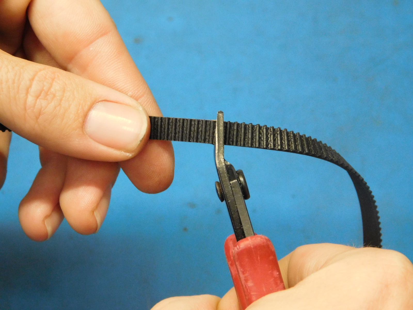
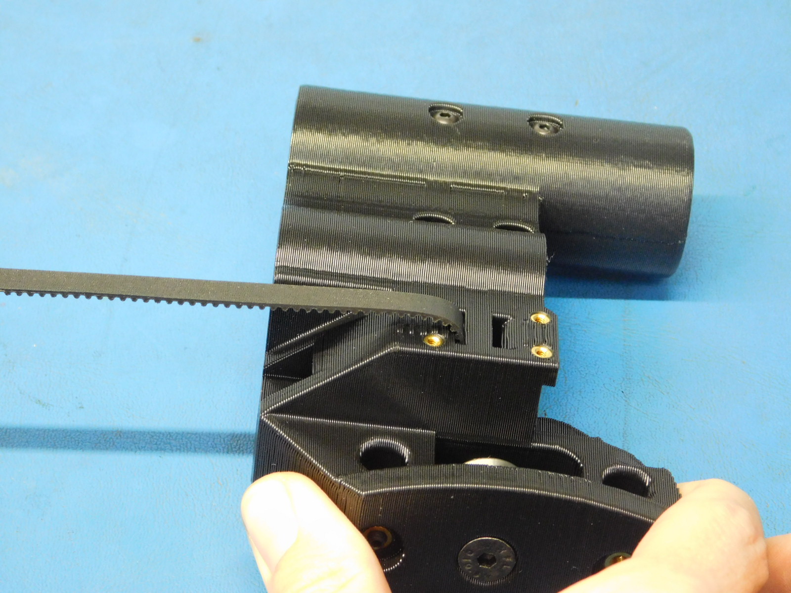
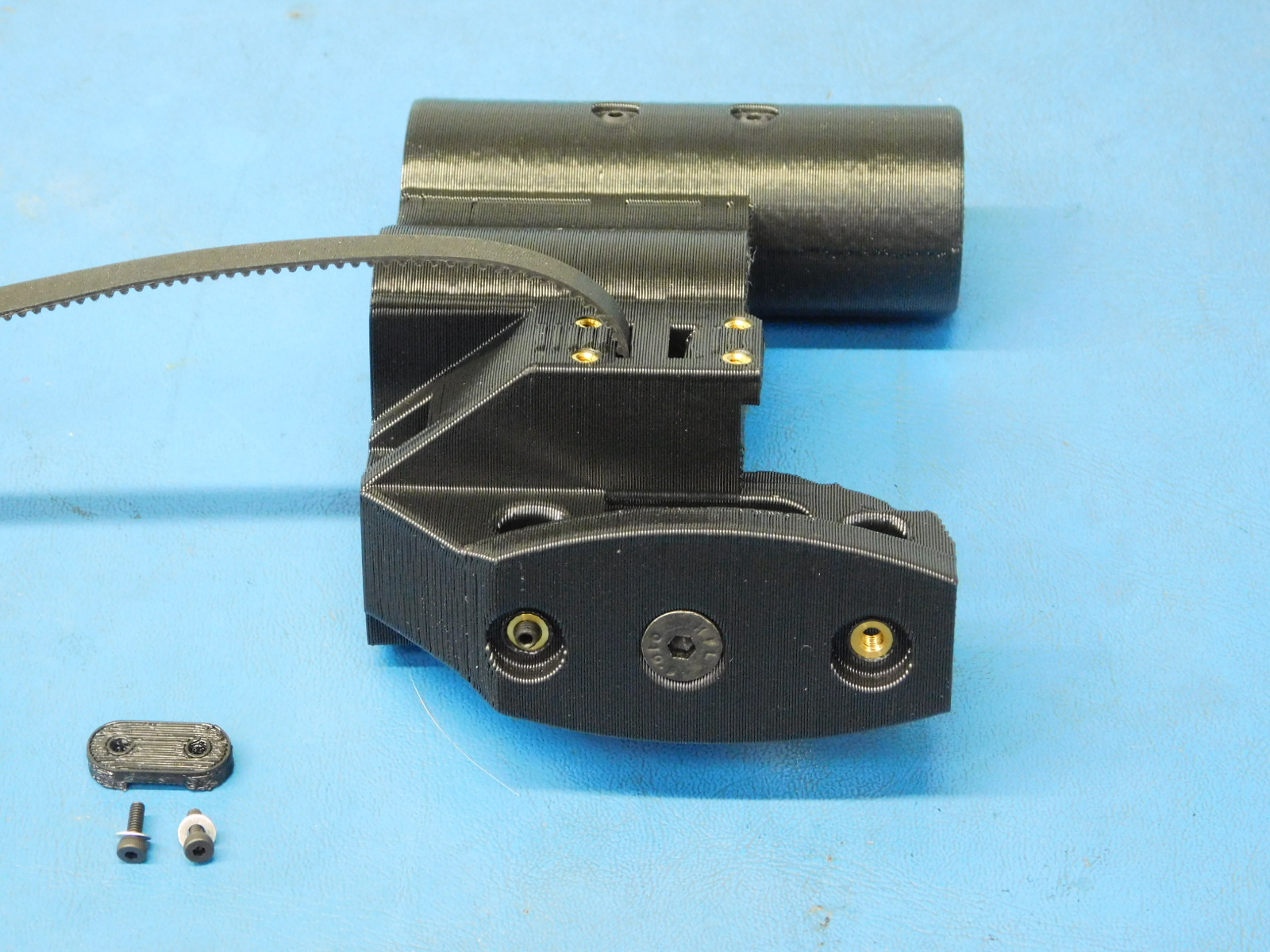
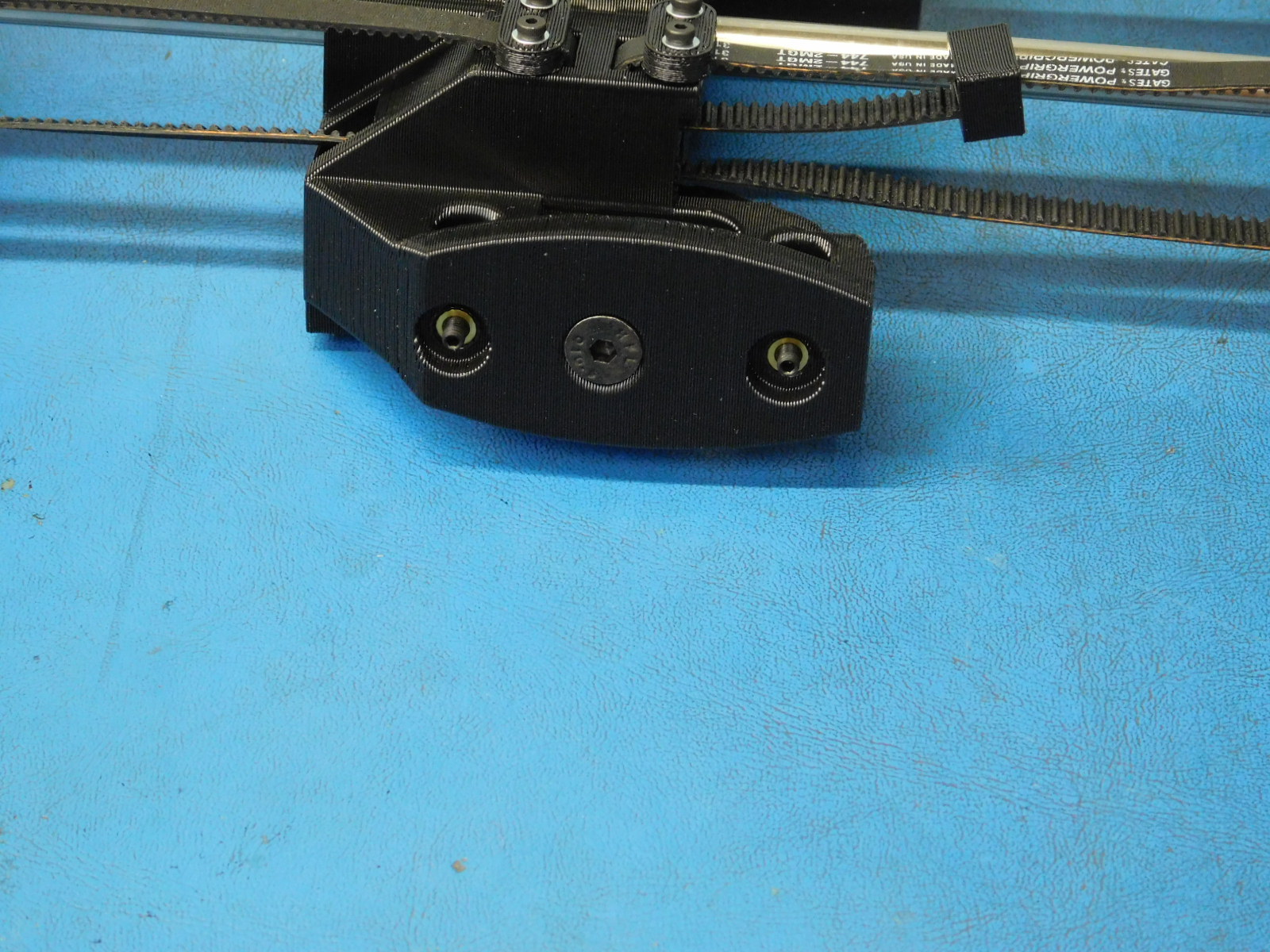
a) Cut a belt [HD-BL0033] straight with the teeth of the belt and insert one end into the lower slot of the Z-Belt clamping feature. Secure in place using one Z-Belt Clamp [PP-GP0308] with two M2x6 SHCS [HD-MS0230] with washers [HD-WA0012].
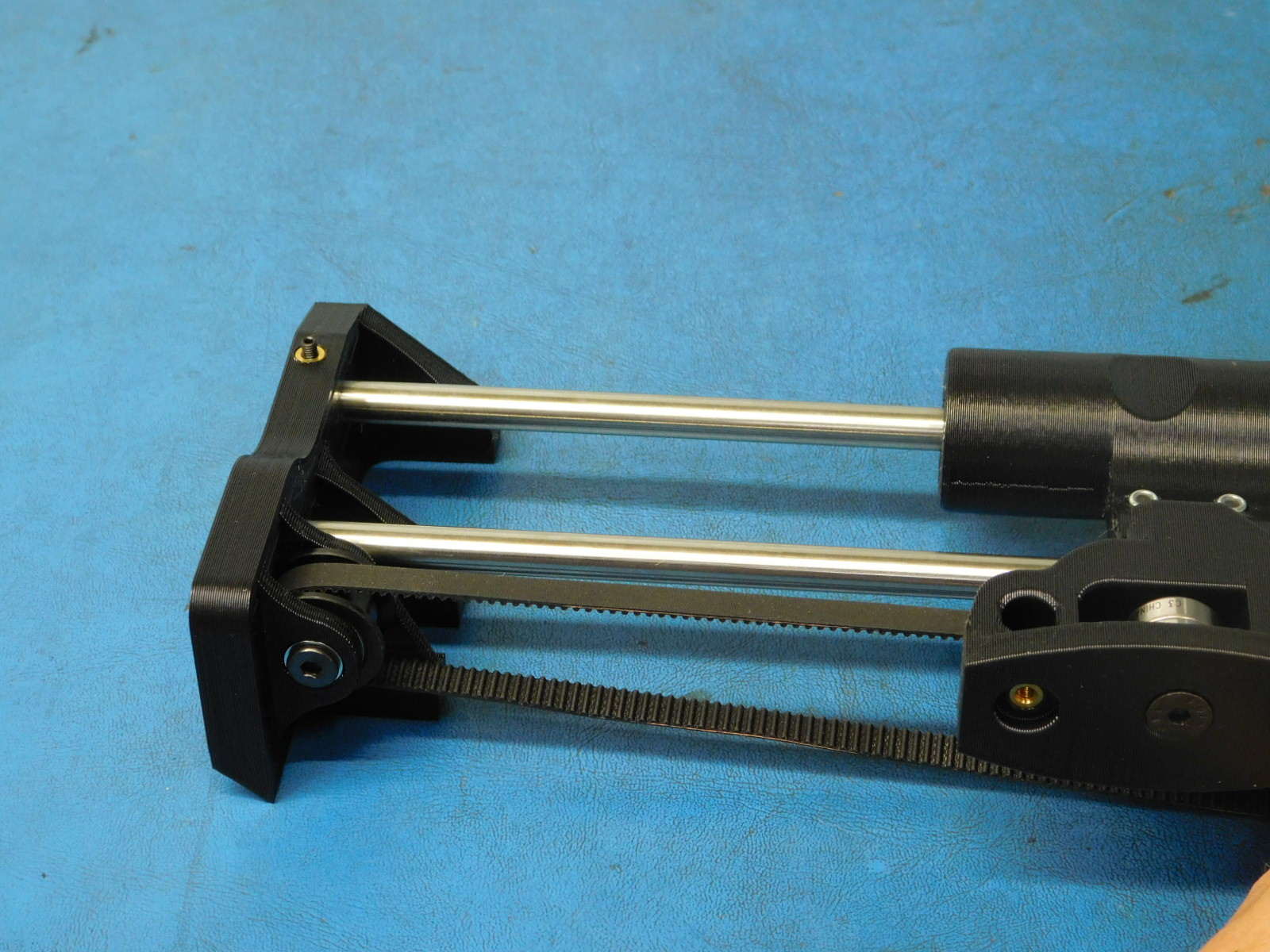
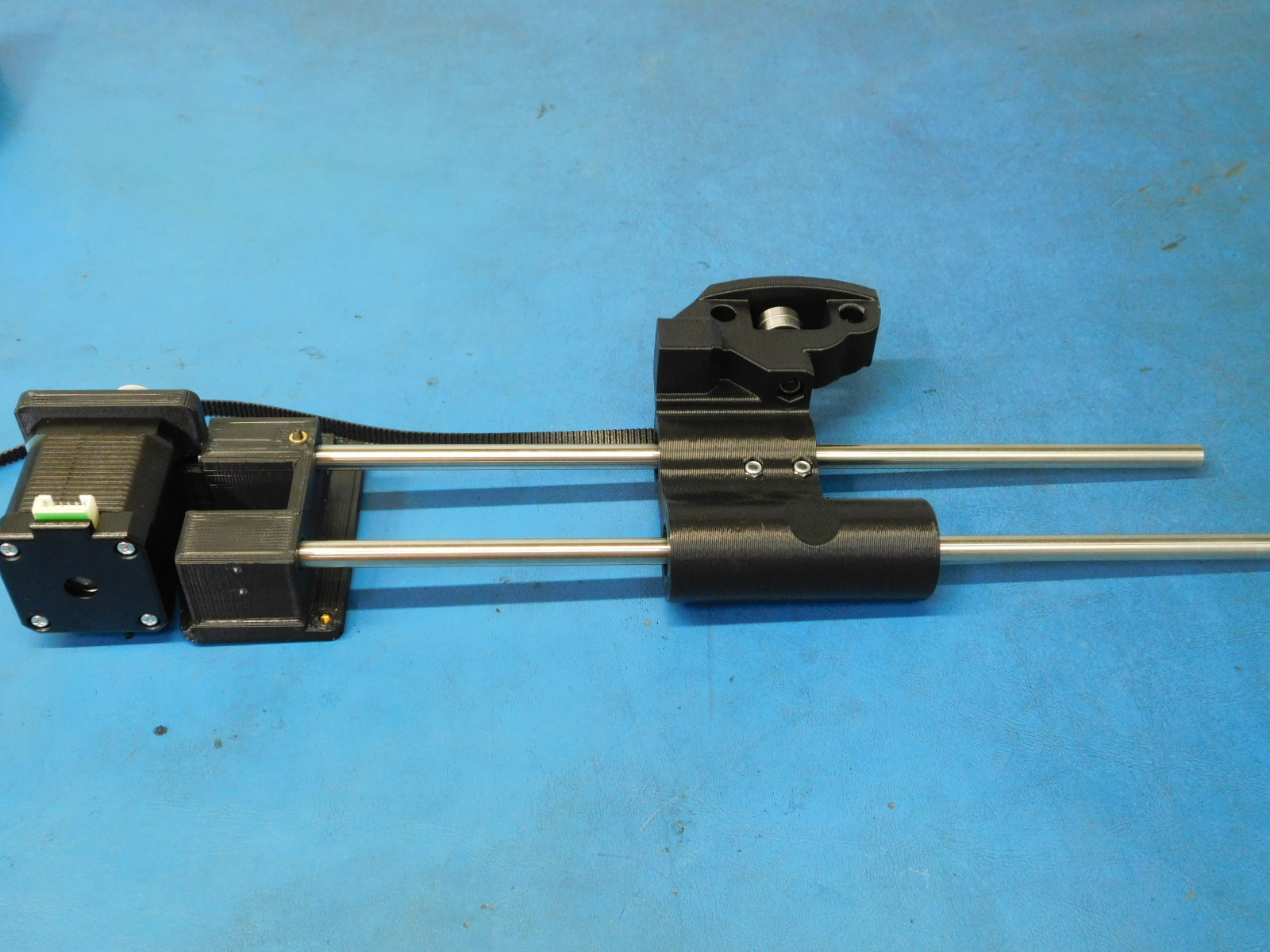
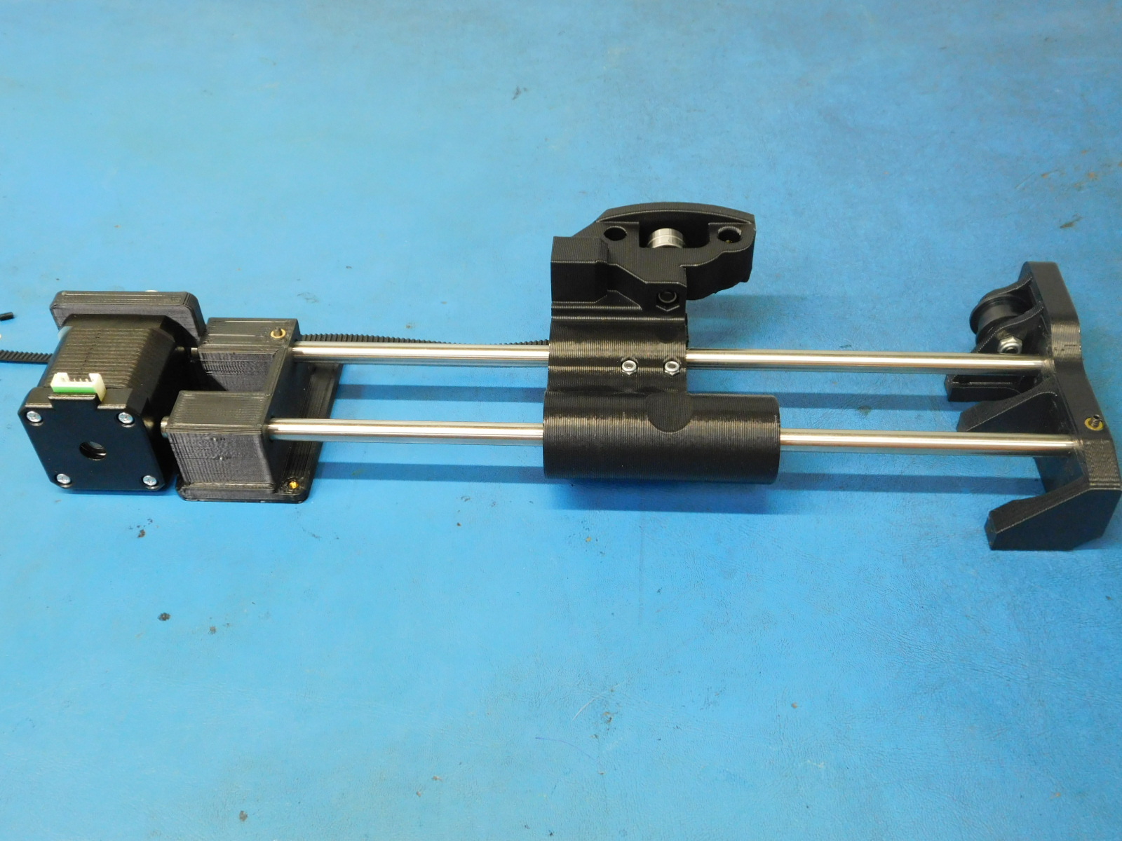
b) Insert 2x smooth rods [HD-RD0035] into the X-End Idler [PP-GP0087].
c) Insert the bottom end of the 2x smooth rods into the z-lower right sub-assembly.
d) Insert the top end of the 2x smooth rods into the slots in the z-upper right sub-assembly.
c) Check to ensure set screws are in the X-End Idler.
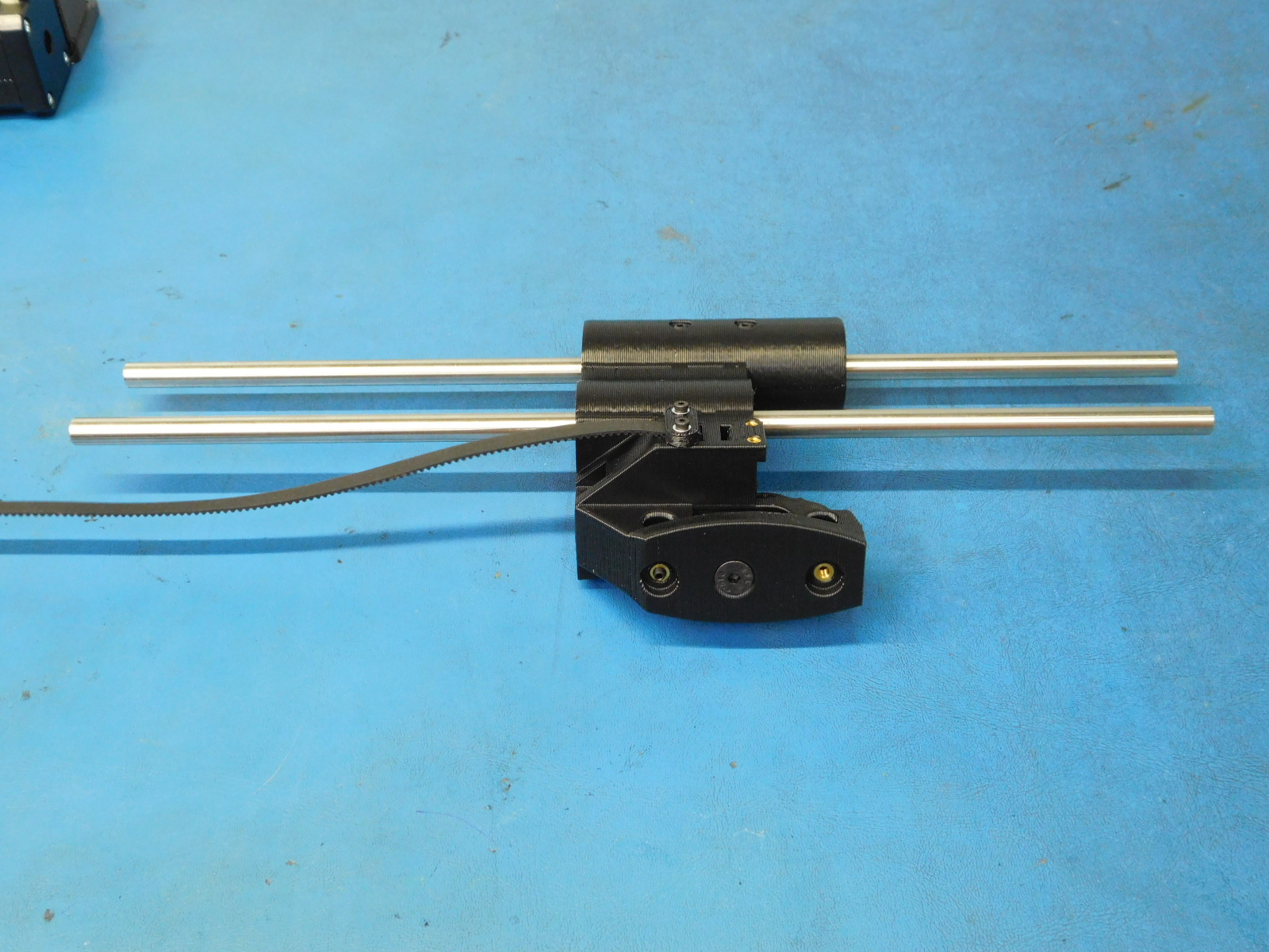
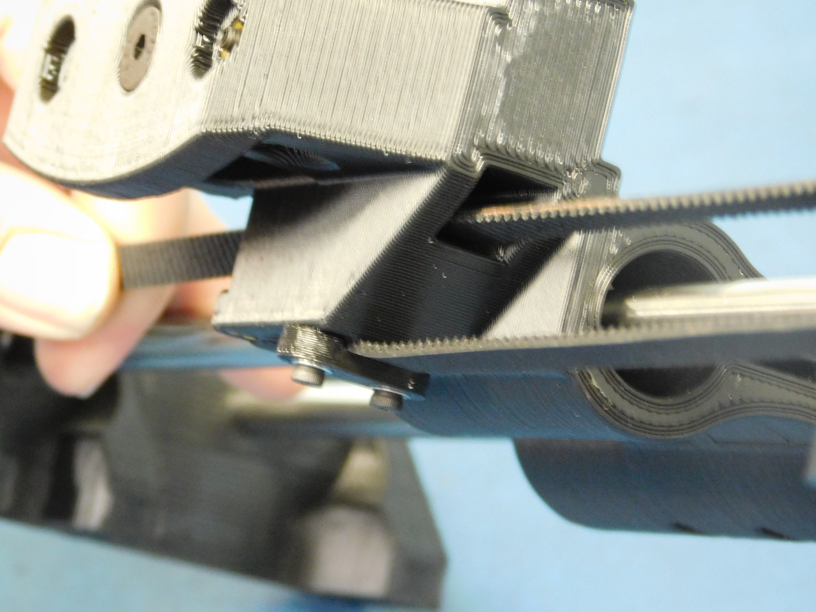
a) Route the belt down around the Z-Motor pulley and up through the hole in the X-End Idler [AS-PR0087]
b) Continue through the bearing in the Z-Upper Right [AS-PR0088] so that the belt makes a loop back to the X-End Idler without twisting.
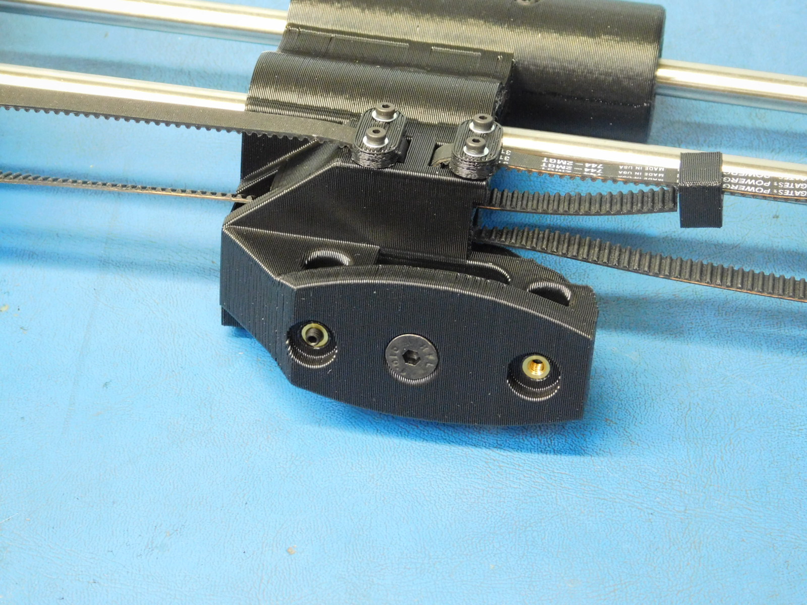
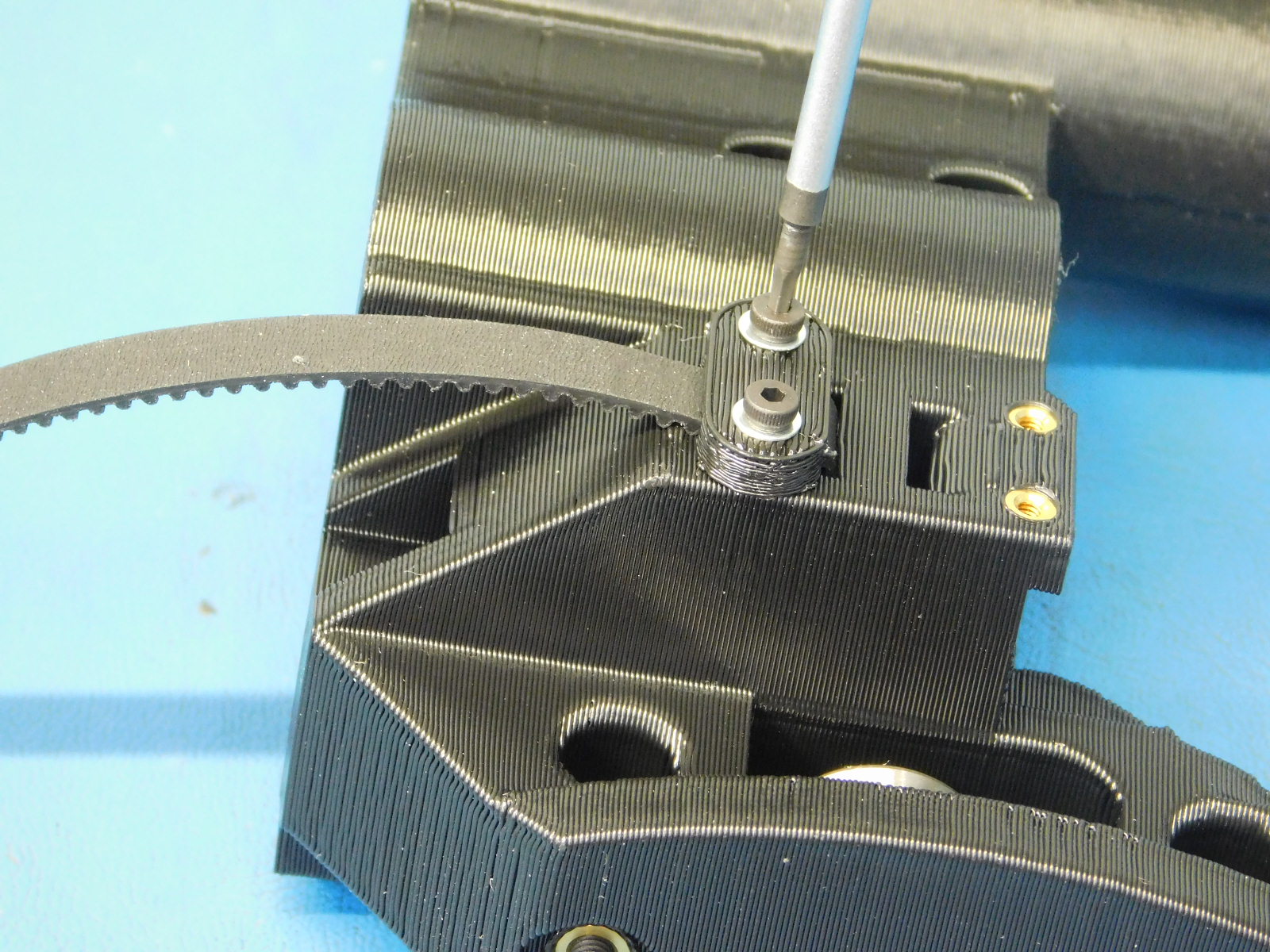
c) Install one Belt Tensioning Collar [PP-GP0307] onto the belt with the narrow end facing the Z-Upper Right Assembly [AS-PR0088] and the slack retaining side facing the inside of the printer.
d) Slide the belt through the upper slot of the Z-Belt clamping feature; Secure in place using one Z-Belt Clamp [PP-GP0308] with two M2x6 SHCS [HD-MS0230] with washers [HD-WA0012]