Open HardwareAssembly Instructions
Guides for installation and assembly of the LulzBot line of products made by Aleph Objects, Inc.
Guides for installation and assembly of the LulzBot line of products made by Aleph Objects, Inc.
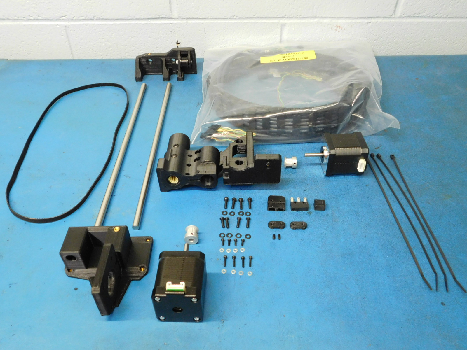
Materials required for AS-PR00:
1x- [AS-PR0090] X end motor assembly with inserts and bushings, Mini 2
1x- [AS-PR0091] Z Upper Left Assembly, Mini 2
1x- [PP-GP0307] Belt Tensioning Collar
2x- [PP-GP0308] Z Belt Clamp
1x- [PP-GP0332] Bump Stop
1x- [] Z Lower Left With Inserts, Mini 2
1x- [EL-HR0130] Mini X Extruder Harnesses Assembly - Rev IR
2x- [EL-MT0029] NEMA 17 Stepper Motor, Moons' - NOT INCLUDING wire harness
1x- [EL-SW0022] SWITCH BASIC SPDT 3A .110QC 125V
1x- [HD-BL0033] Timing belt, 372 teeth, GT3 2mm pitch, 744 mm pitch length, 6 mm belt width, Neoprene
2x- [HD-BT0012] M3 Set Screw (Grub Screw)
4x- [HD-BT0039] Socket Head Cap Screw M3 Thread, 12MM Length
4x- [HD-BT0107] Socket Head Cap Screw M2 Thread, 10mm Length
4x- [HD-BT0128] M3 x 6 Bolt, FHCS Black-Oxide
4x- [HD-BT0146] M3 x 12 BHCS, Black Oxide, Class 10.9 Steel
2x- [HD-MS0033] GT2, 16 Teeth, timing pulley
4x- [HD-MS0058] Wire Tie, 8" Black, pk 1000
4x- [HD-MS0230] Socket Head Cap Screw M2 Thread, 6mm Length
2x- [HD-RD0035] 8mm Smooth rod, 315mm, 300 Series Stainless Steel
8x- [HD-WA0012] Steel Flat Washer, M2 screw size, 5mm OD
8x- [HD-WA0038] Black-Oxide 18-8 Steel Flat Washer, M3 Screw Size, 3.2mm ID, 7.0mm OD
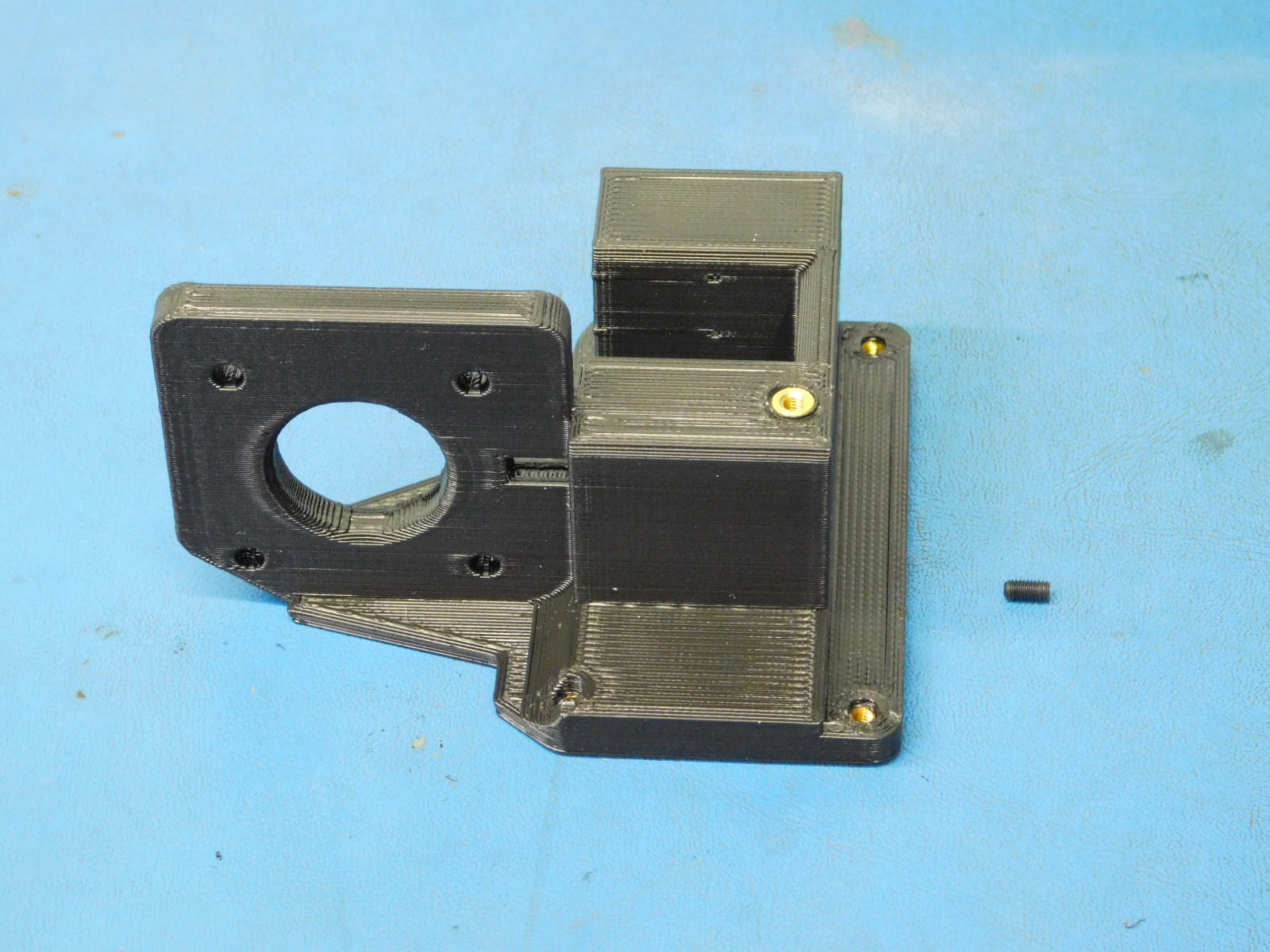
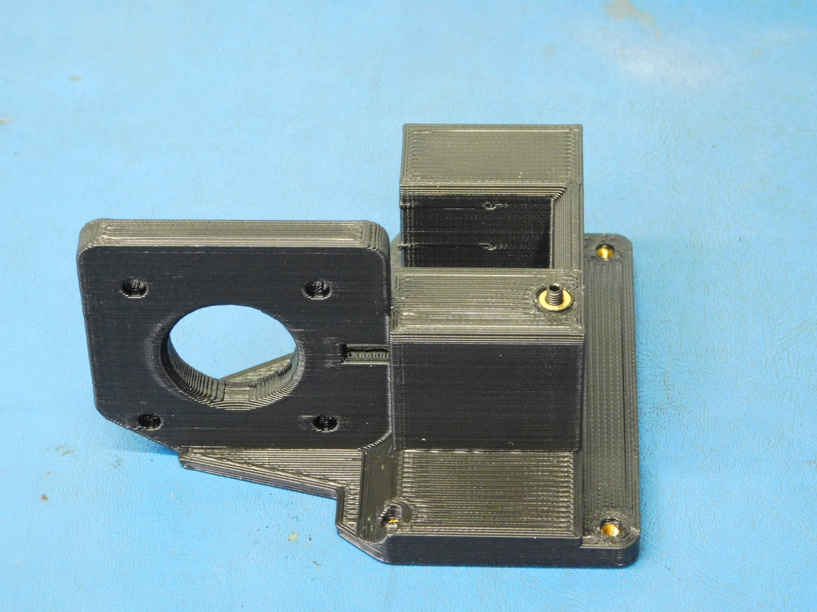
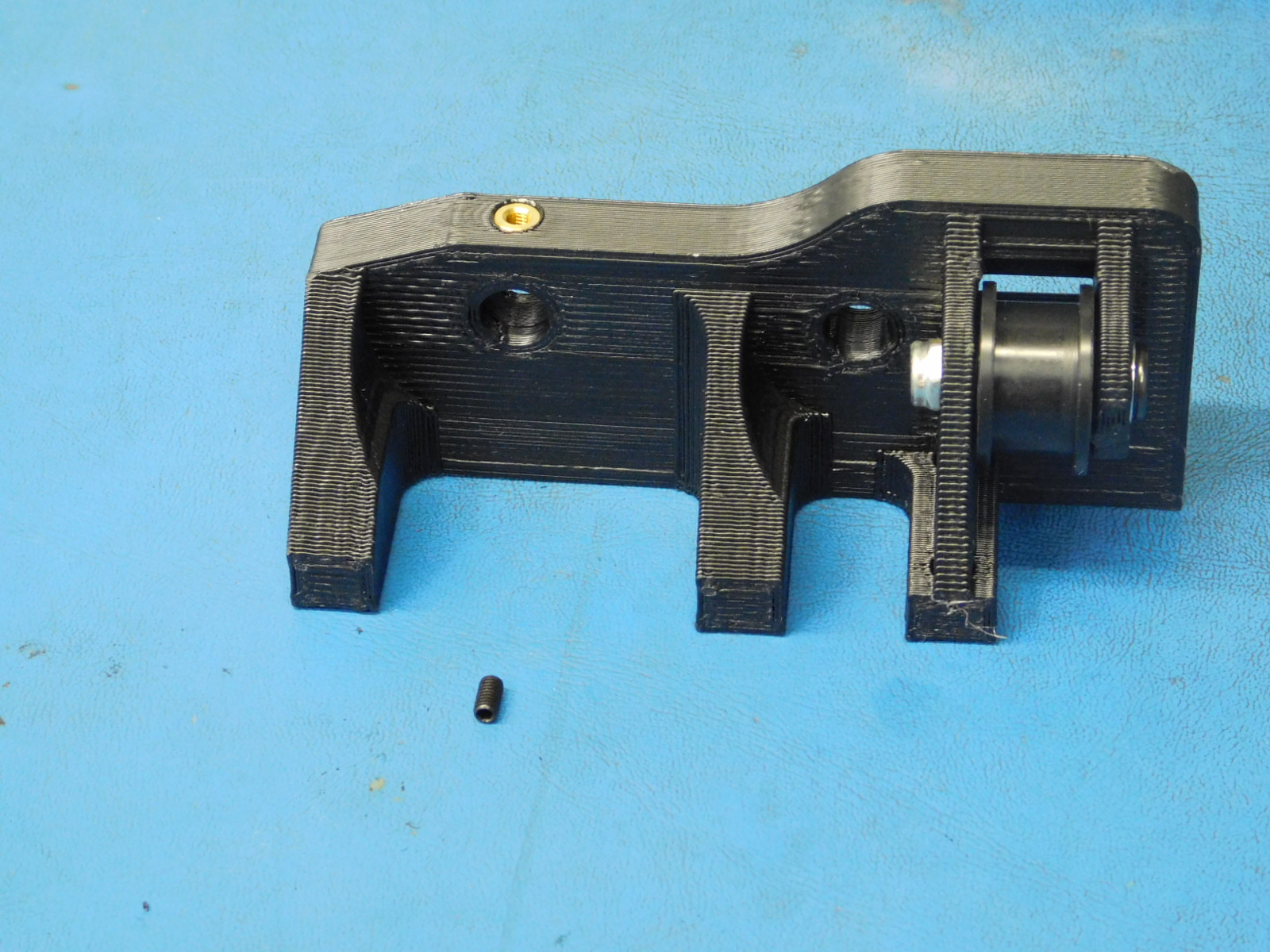
a) Using an 8mm part reaming tool, ream the 8mm smooth rod hole on the Z-Lower left printed part [PP-IS0124] that has the M3 insert by turning the reamer clockwise in the hole. Be careful to NOT remove to much material causing the smooth rods to sit loose.
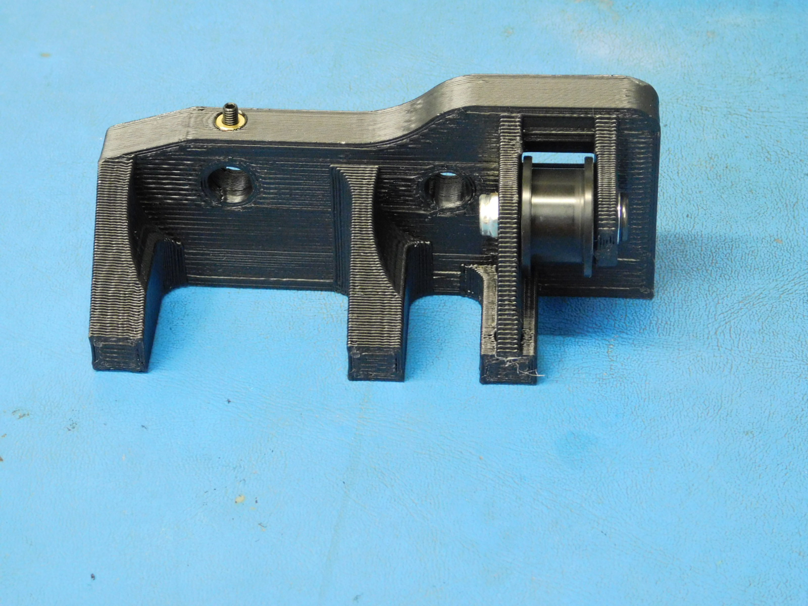
b) Insert a set screw [HD-BT0012] into the designated place on the z-lower left.
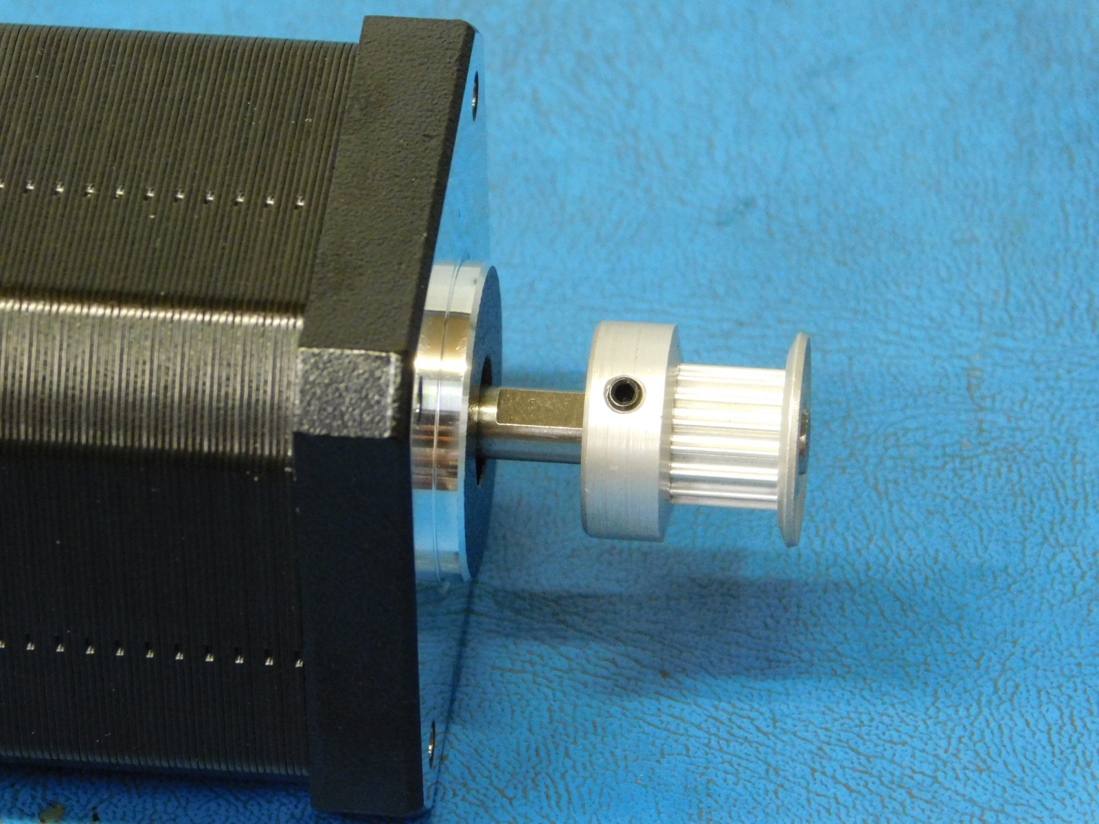
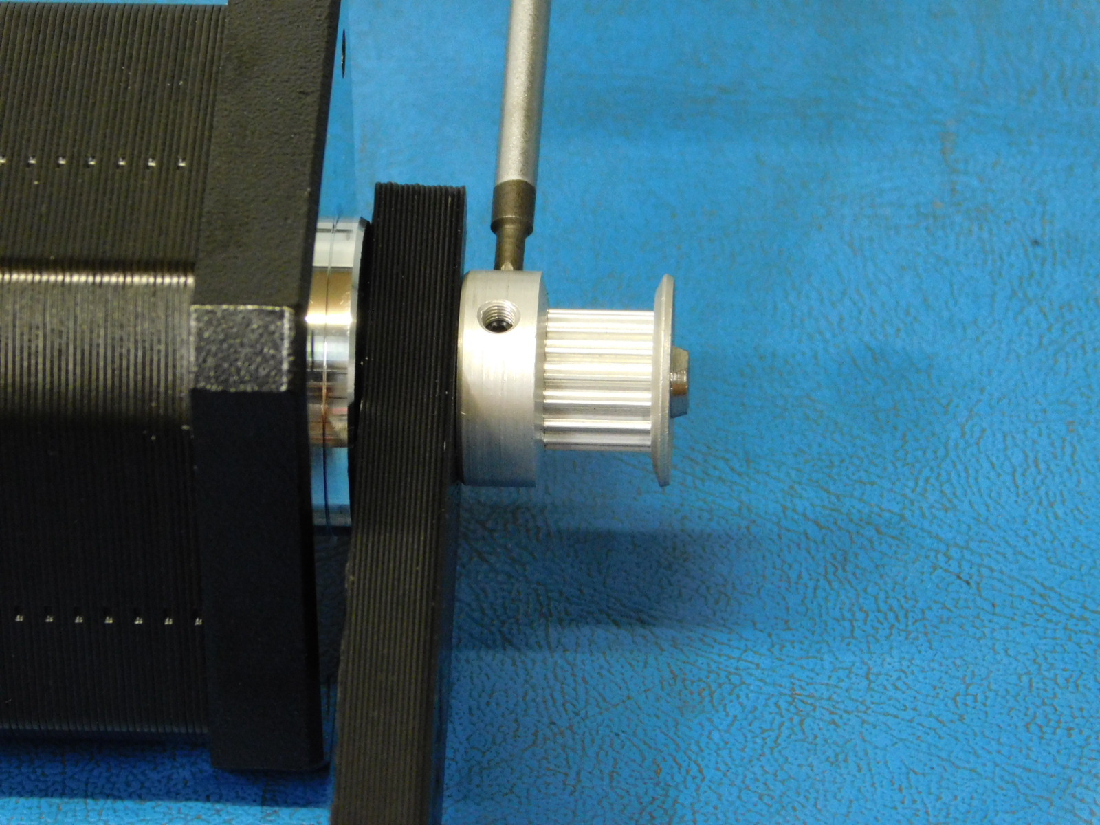
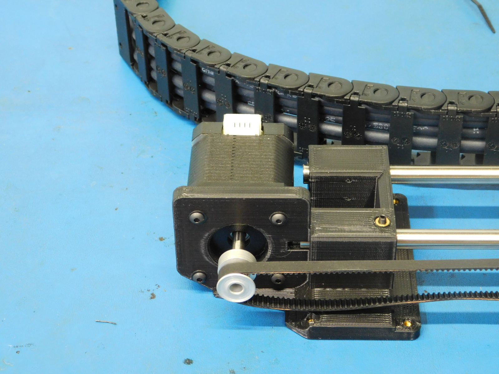
c) Attach a Pulley [HD-MS0033] to a Motor [EL-MT0029] offset the pulley from the face of the motor 13mm. Use the printed jig to ensure consistency. Ensure one of the pulley set screws is aligned with the flat segment of the motor shaft and the other set screw is position on the left side of the motor and tighten securely.
c) Secure the motor to the z-lower left with 4x- M3x12 BHCS [HD-BT0146] with 4x- M3 washers [HD-WA0038] , tighten screws to 8 in*lbs.
d) Insert a set screw [HD-BT0012] into the z-upper left [AS-PR0091].
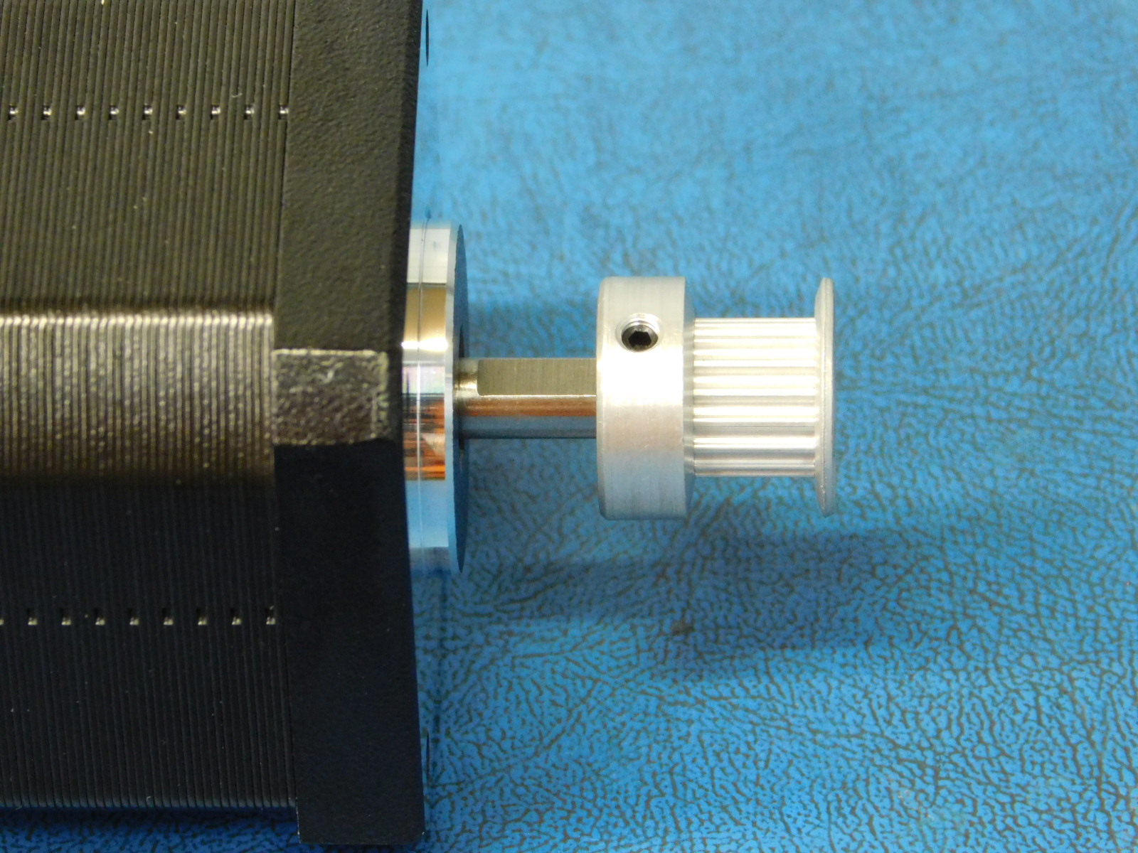
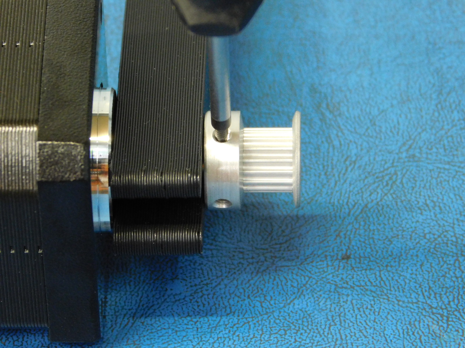
Attach a pulley [HD-MS0033] to a motor [EL-MT0029] , offset the pulley 6mm from the face of the motor, ensure one of the pulley set screws is aligned with the flat segment of the motor shaft, secure pulley in place with two set screws already installed in the pulley, tighten screws securely.
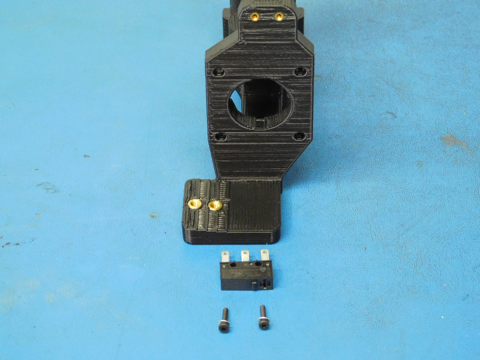
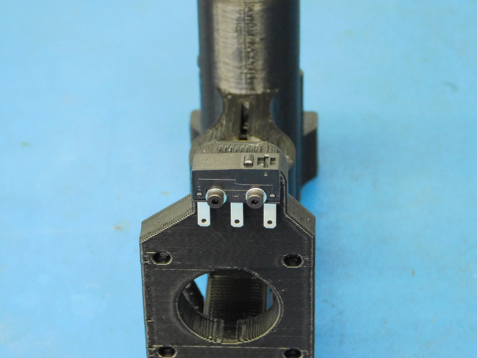
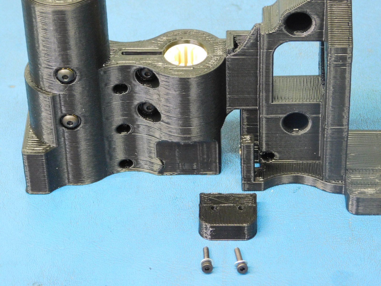
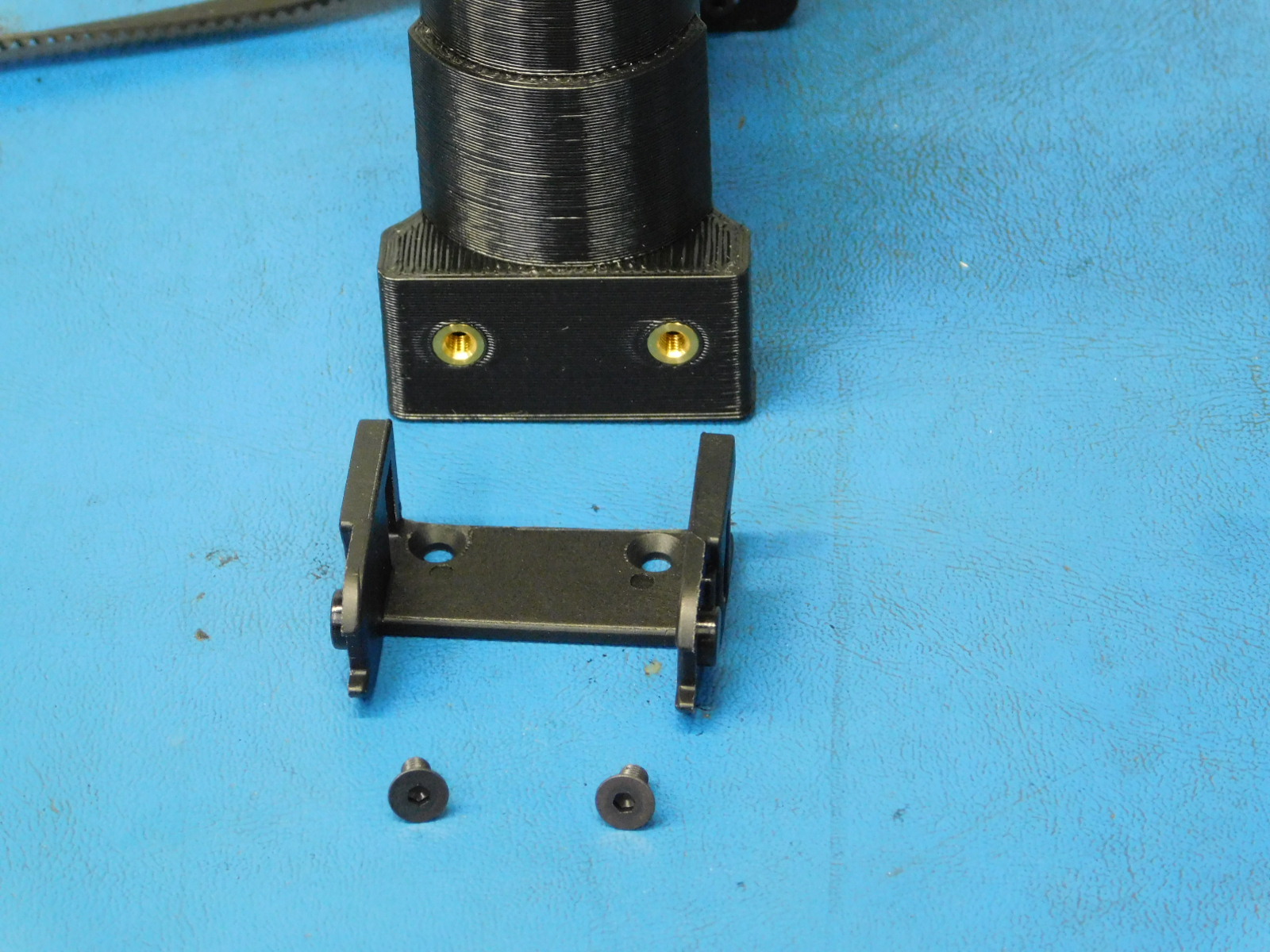
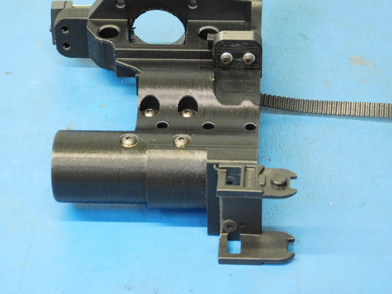
a) Align and install the Z-Max End Stop switch [EL-SW0022] with the switch mount located above the motor mount of the X-End Motor part, Secure the switch with 2x- M2 x 10 SHCS [HD-BT0107] and M2 SS washers, [HD-WA0012] tighten screws to 3 in*lbs.
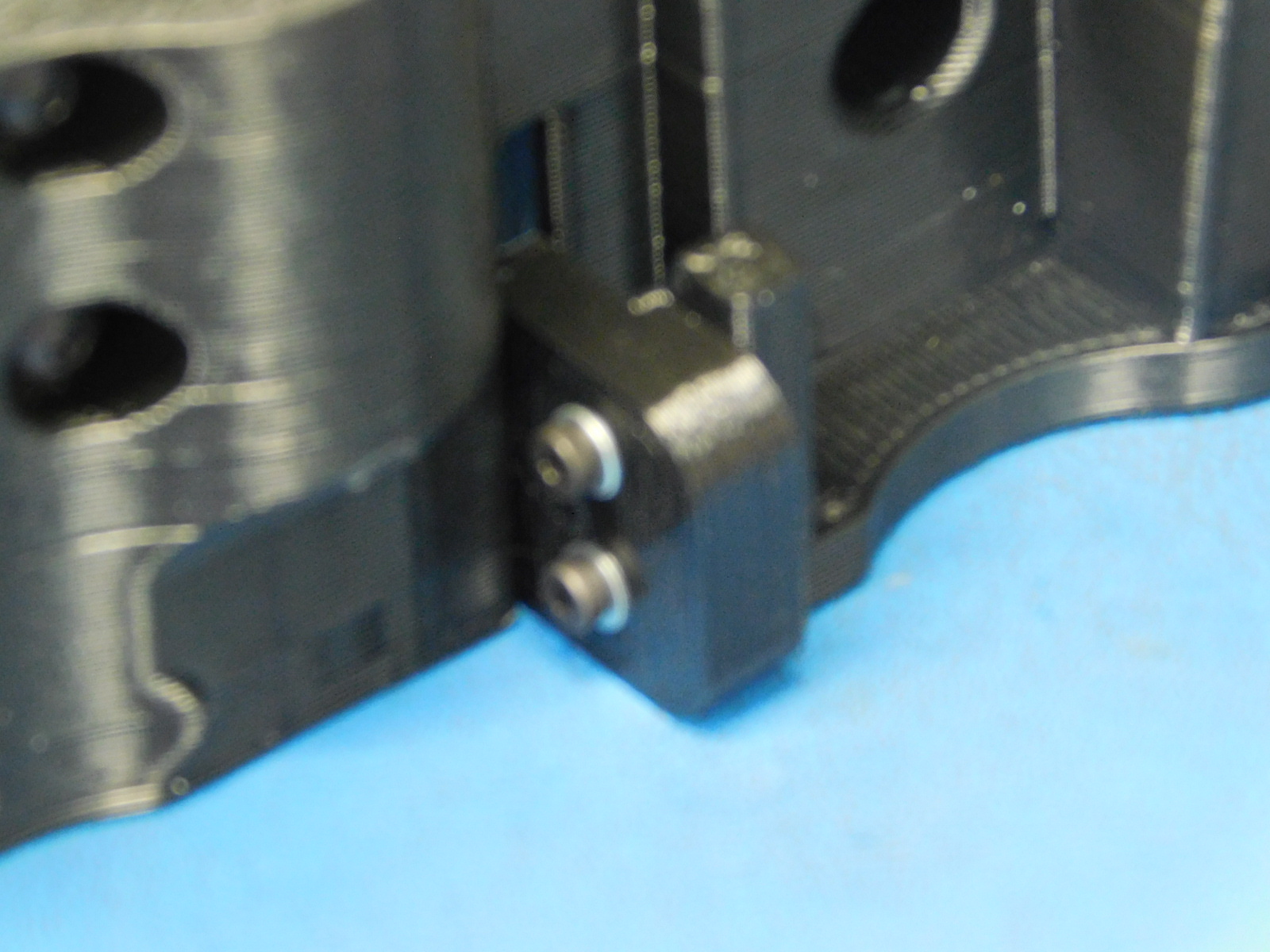
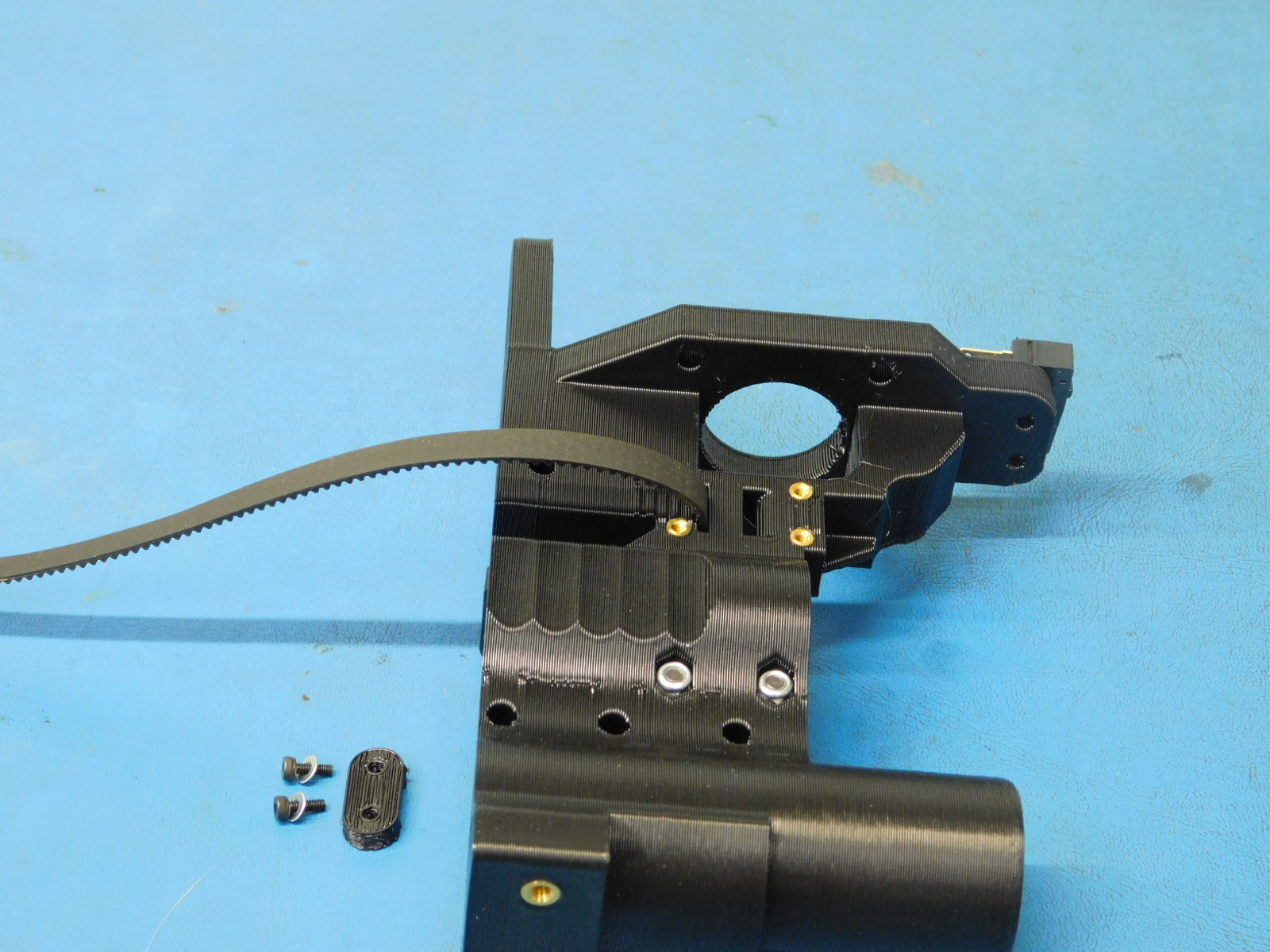
b) Align and install the Bump Stop [PP-GP0332] with the mount located in the middle of the X-End Motor part as pictured. The Bump Stop should be oriented with the flat side facing away from the belt path. Secure the Bump Stop with 2x- M2x10 SHCS [HD-BT0107] with M2 washers [HD-WA0012], tighten screws until the Bump Stop no longer moves freely.
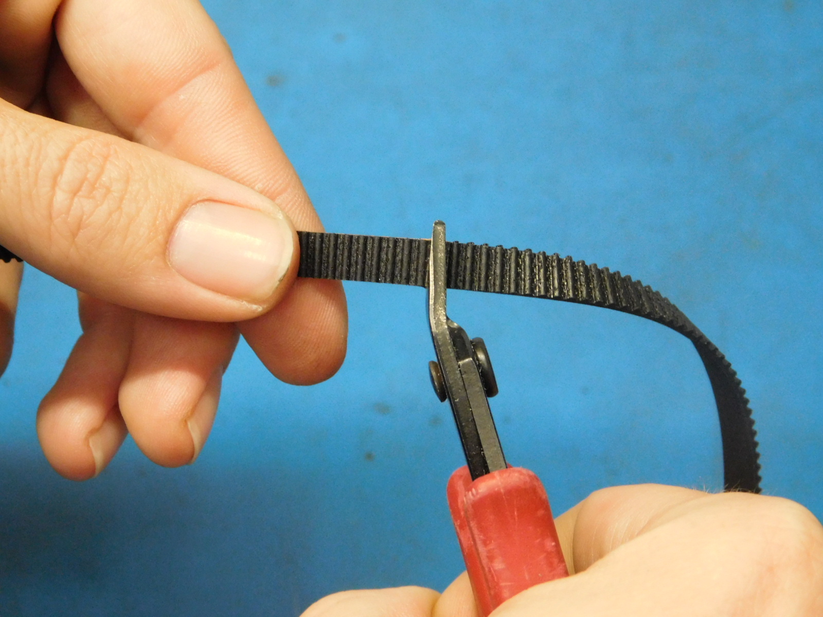
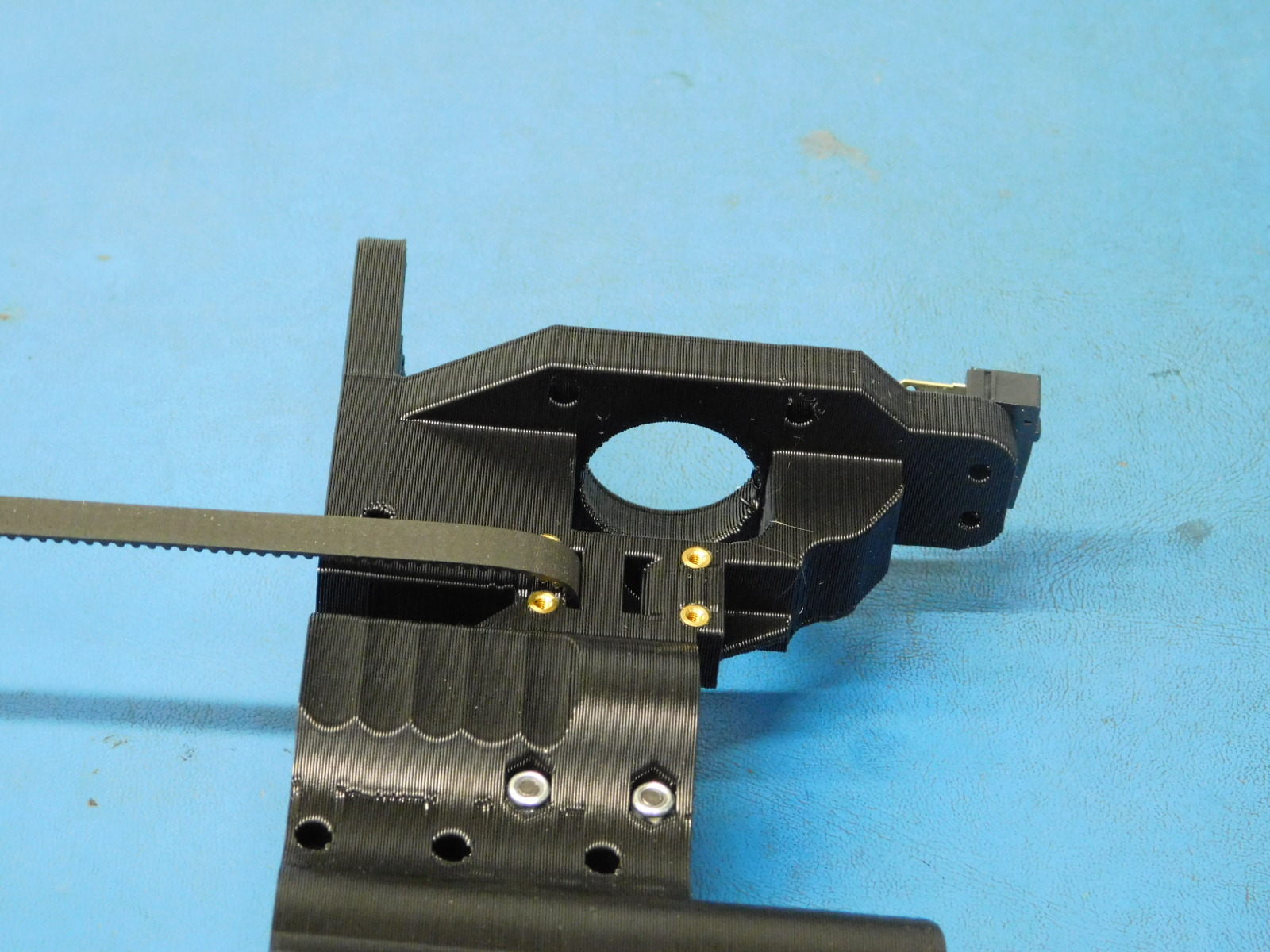
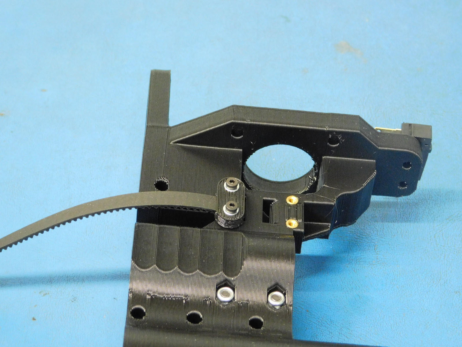
c) Cut a belt [HD-BL0033] straight with the the teeth of the belt and insert one end into the lower slot of the Z-Belt clamp feature. Clamp the belt in place using one Z-Belt Clamp [PP-GP0308] and two M2x6 SHCS [HD-MS230] with washers [HD-WA0012]
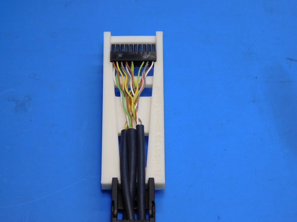
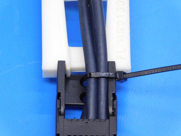
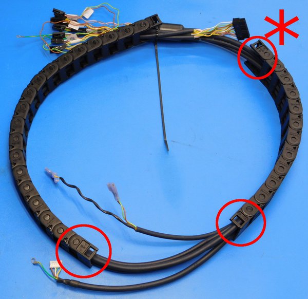
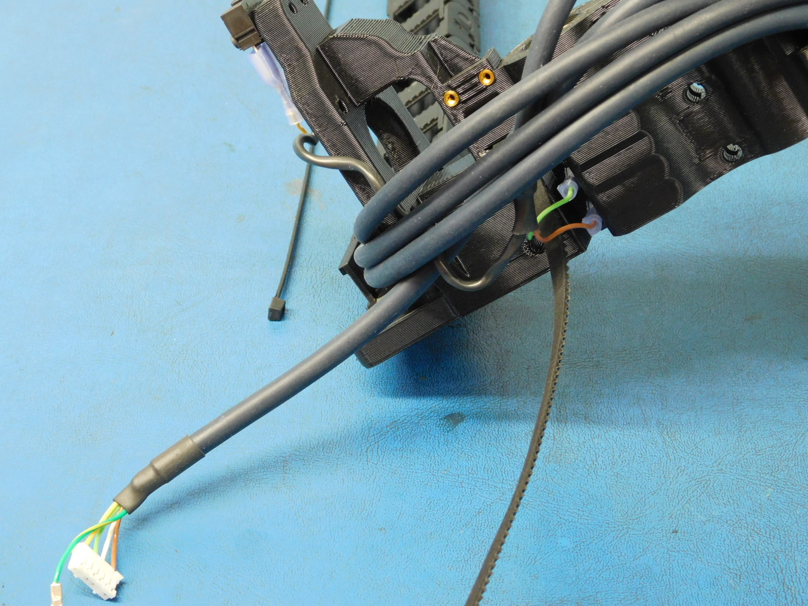
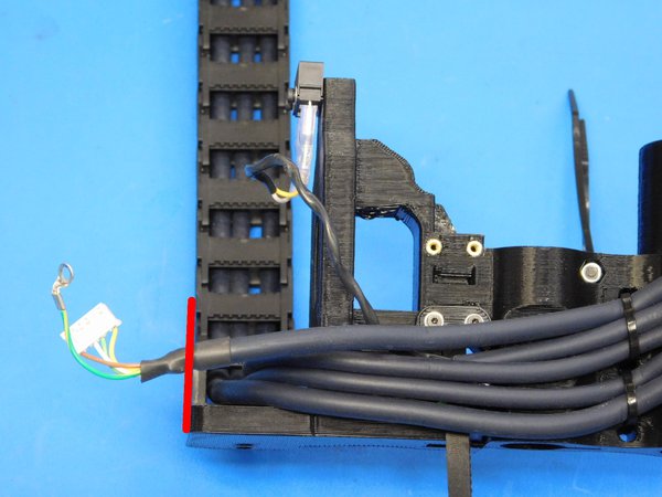
a) Set the 20 position connector at the Extruder end of the cable harness to 90 mm from the back of the connector to the end of the cable chain, using the printed jig. Secure the cable in place with a cable tie.
b) Remove the three highlighted cable chain mount end. Pass the female 30mm cable chain mount to the frame assembly workstation (highlighted with asterisk in, located near the ferrite)
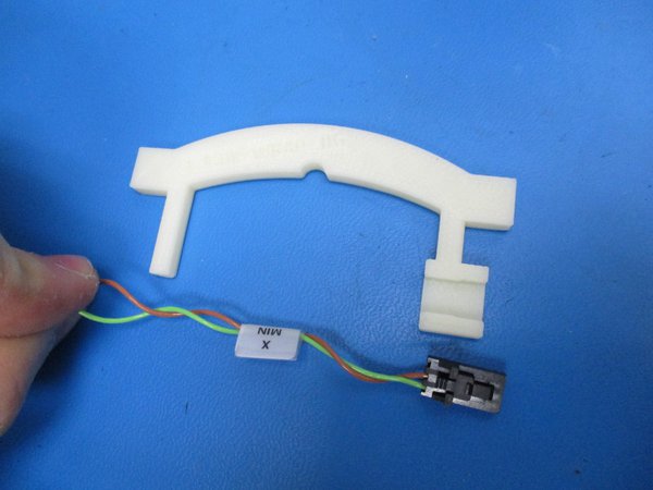
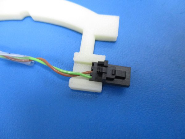
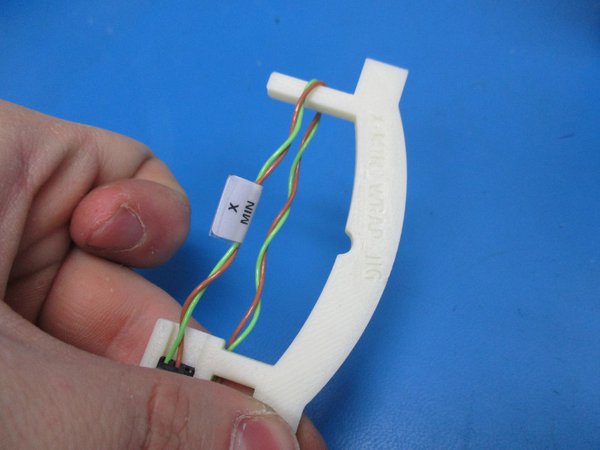
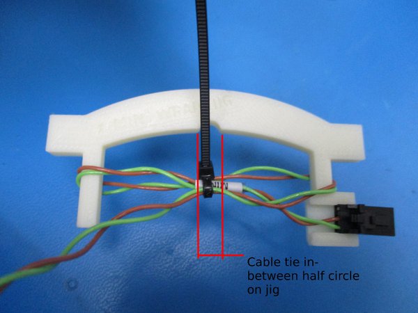
d) Wrap the wires labeled "X-Min" as follows: Snap the molex connector into the jig as shown. Wrap the wire around the far post on the jig and run the wire back to the post closest the molex housing. Wrap the wire around the post closest to the molex housing and run the wire back to the far post. Cable tie the center of the wrapped wires, designated by the half circle in the jig.
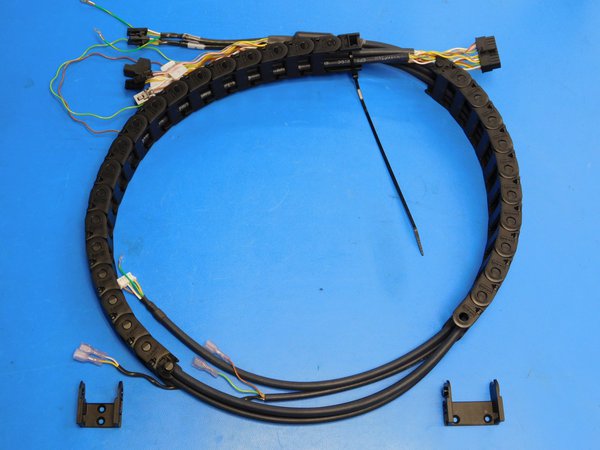
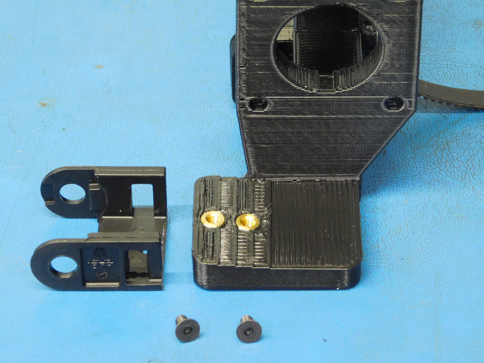
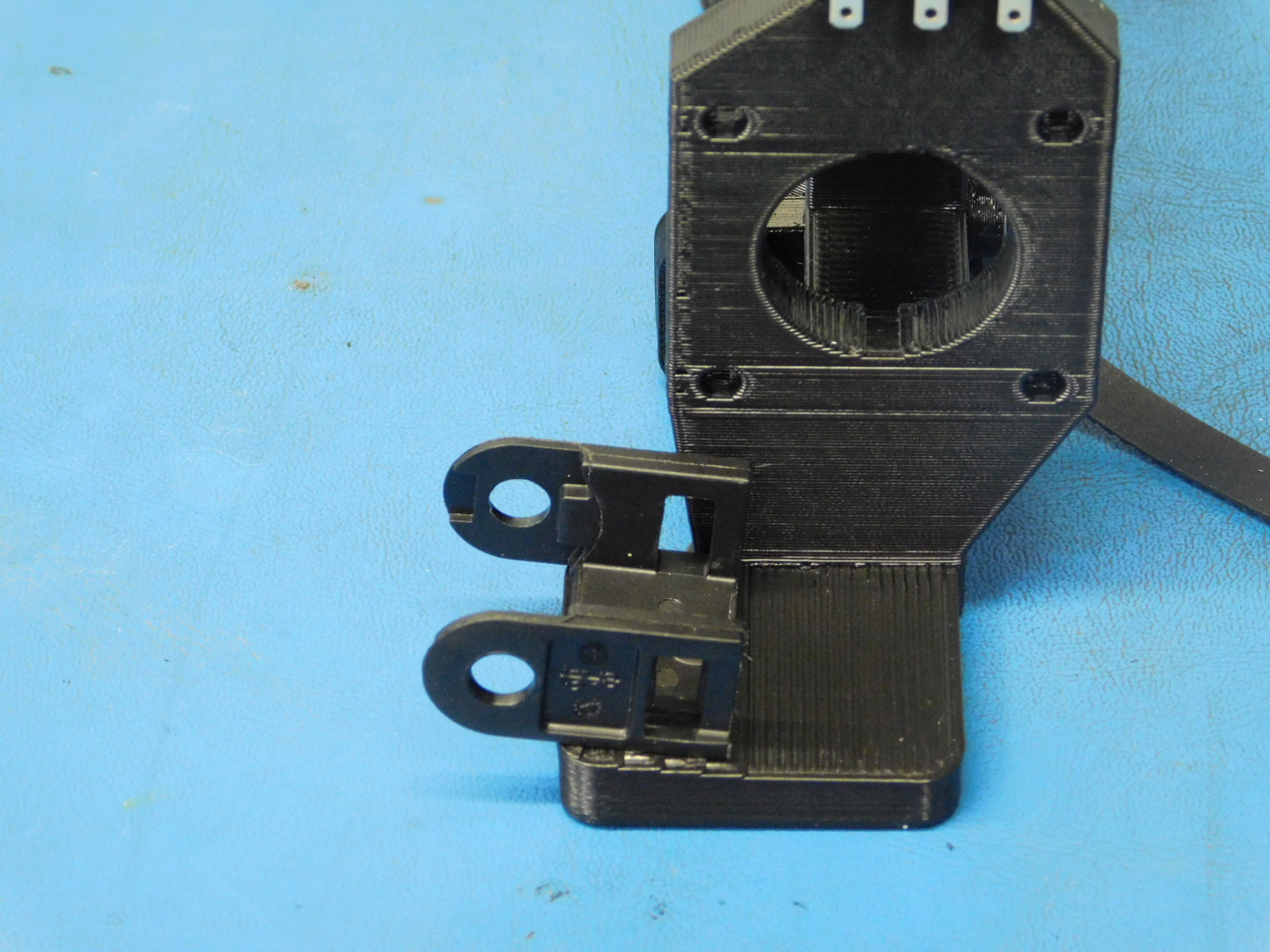
a) Remove and attach the 20mm cable chain mount to the X-End Motor part (Motor mount side), use 2x M3x 6 FHCS [HD-BT0128] black oxide screw, tighten to 5 in*lbs.
b) Remove and attach the 30mm cable chain mount to the X-End Motor part (Drylin bearing side), use 2x M3x 6 FHCS [HD-BT0128] black oxide screw, tighten to 5 in*lbs.
c) Clip the left end of the Y cable chain mount in first to the X-End motor sub-assembly, followed by clipping the right side. Make sure that the number 2 cable is on top of number 1 and that number 1 is tight.
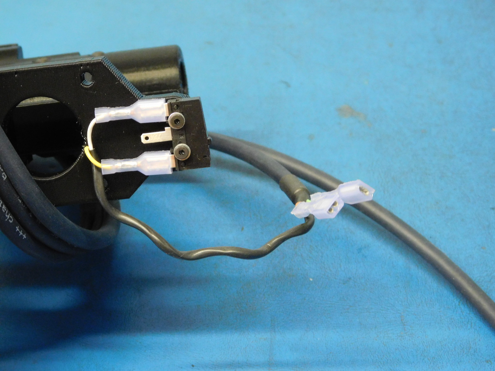
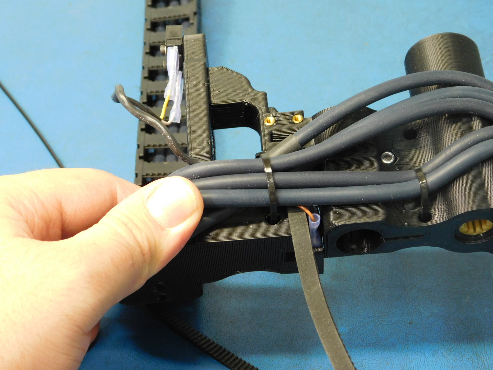
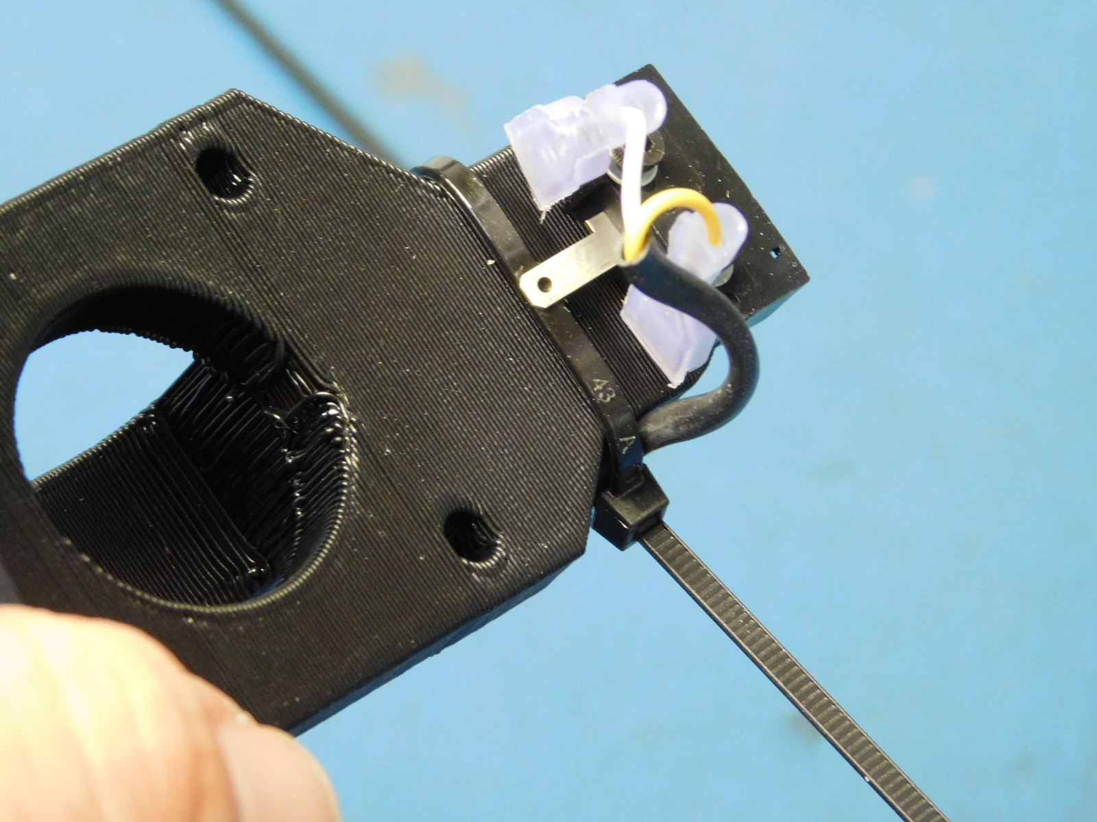
d) Take the z max switch wires (yellow and white) and plug them into the switch on the X-End motor with the yellow wire facing towards belt.
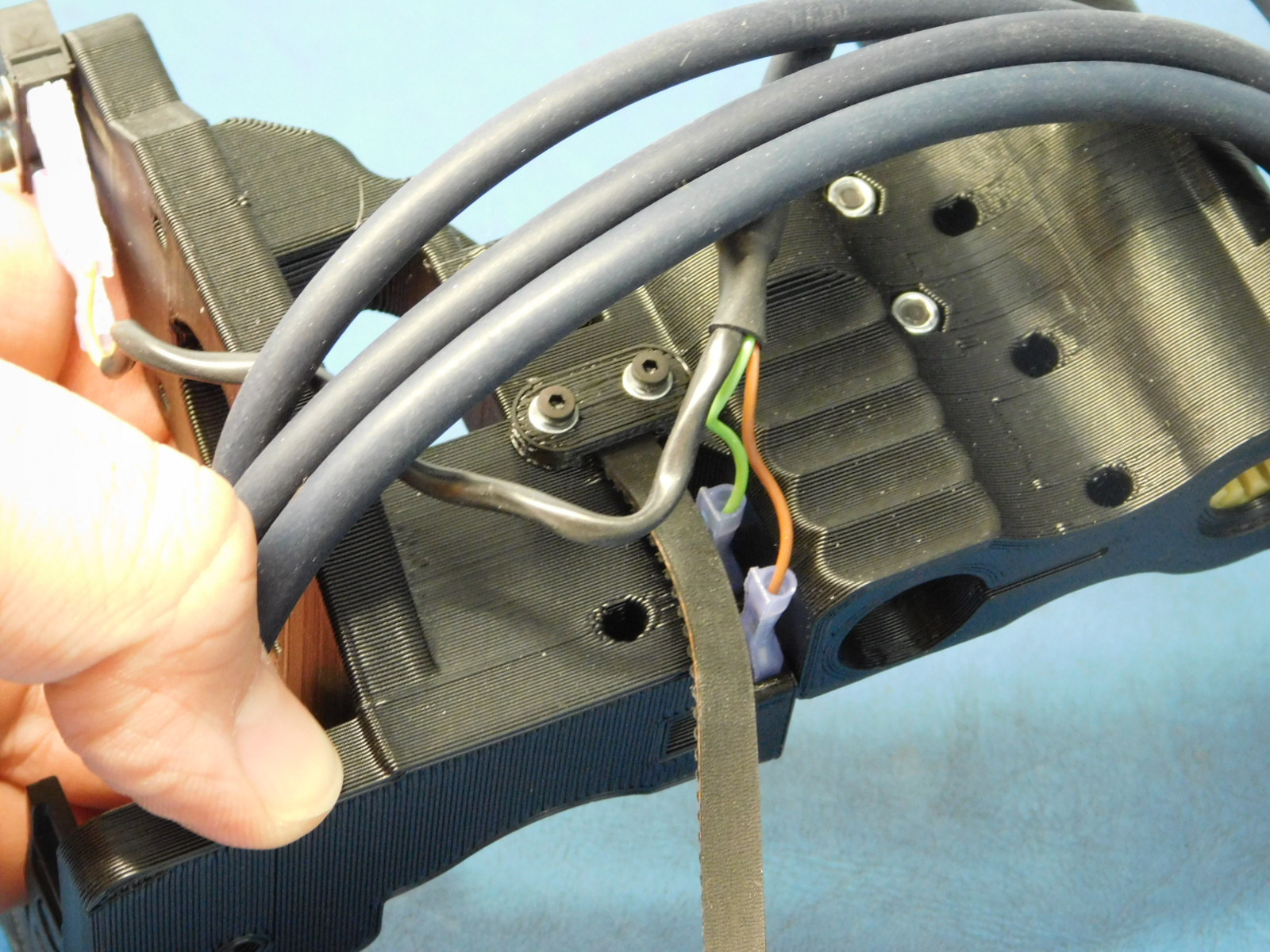
e) Take the bumper cables (green and brown wires) and thread underneath the 3 extruder wires and place them into the bumb stop slots.
f) Take the x-motor connector and thread it underneath all of the wires.
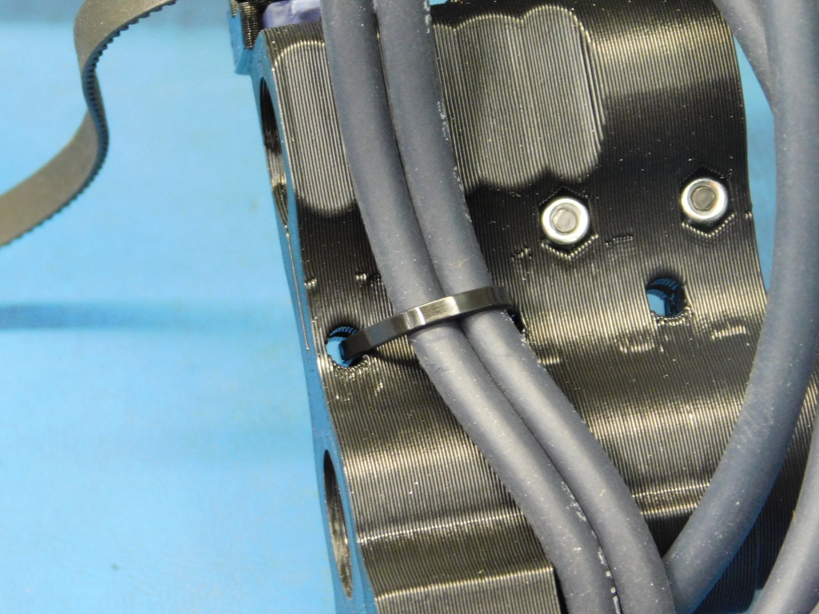
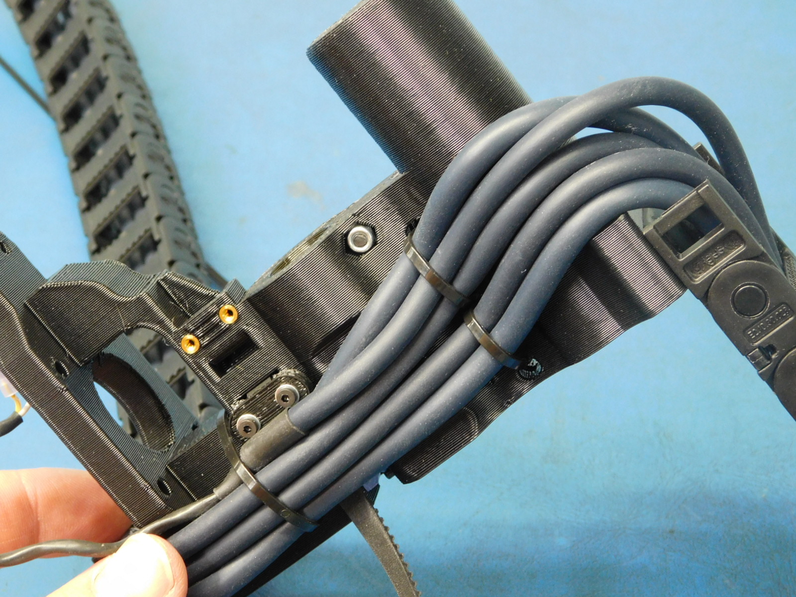
g) Obtain a zip tie [HD-MS0058] and start by threading it through the center hole and over the first 2 wires. Cinch it tight so that the 2 wires lay flat against the part.
h) Obtain another zip tie and thread it through the small hole beneath the pully space of the x-end motor and route the zip tie around all 5 of the cables and start the zip tie. Do not tighten until you have all the wires flat against the part.
i) Obtain a zip tie and start by going through the center hole on the right side and run it around the top 3 wires and out through the top hole. Pull the zip tie tight.

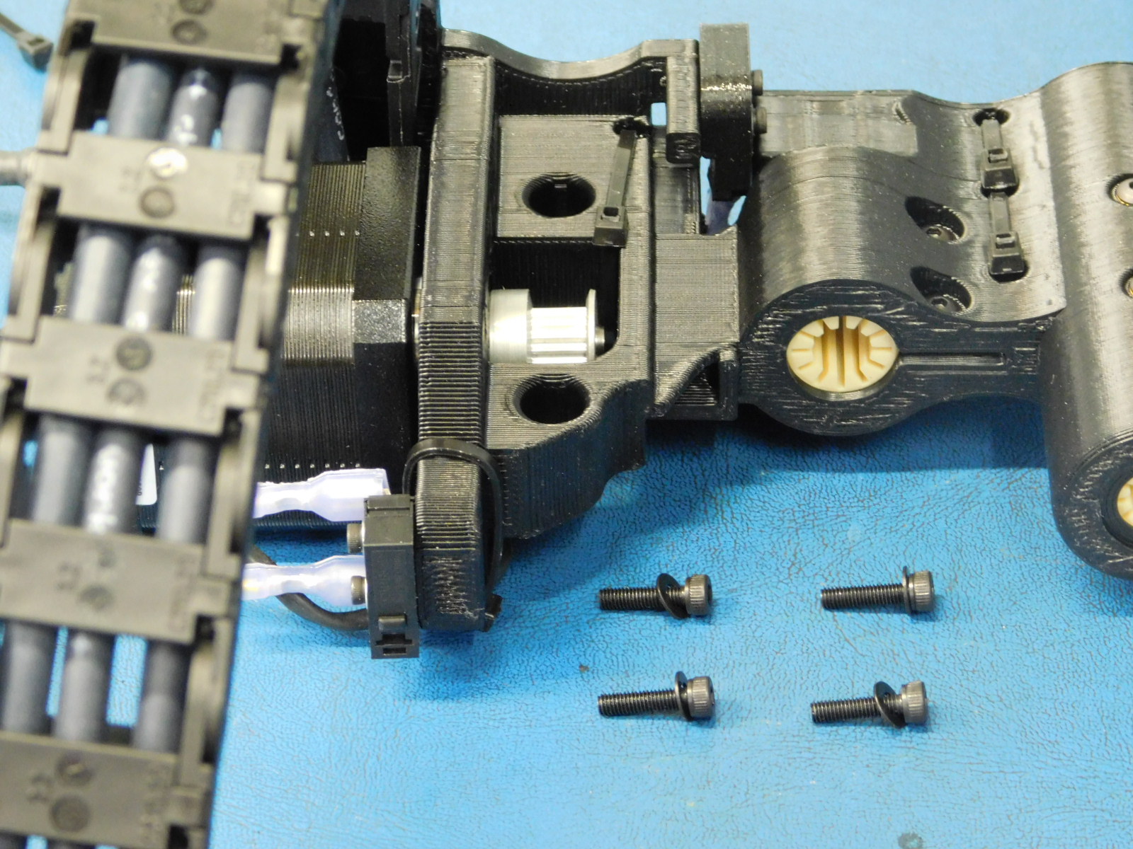
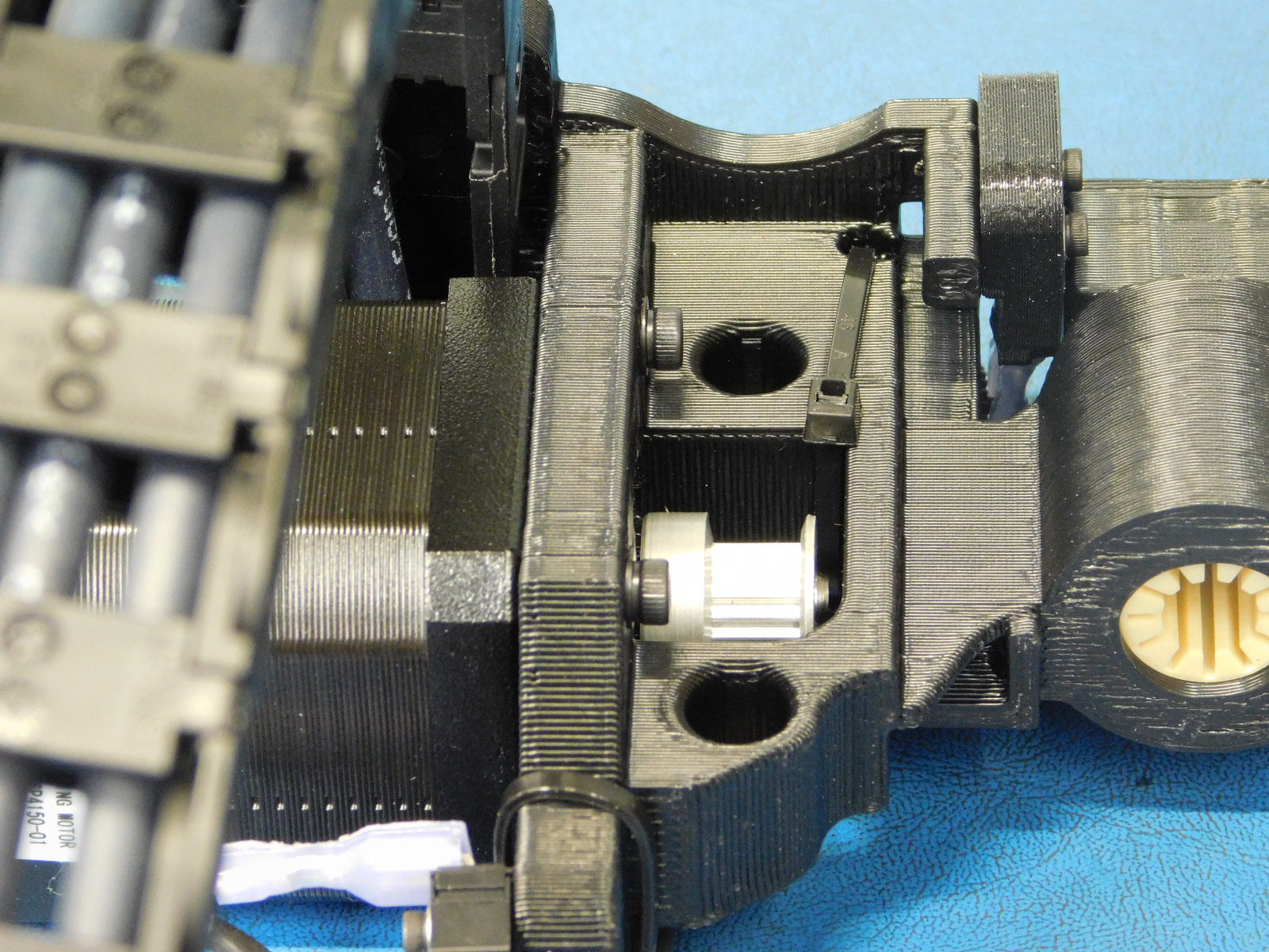
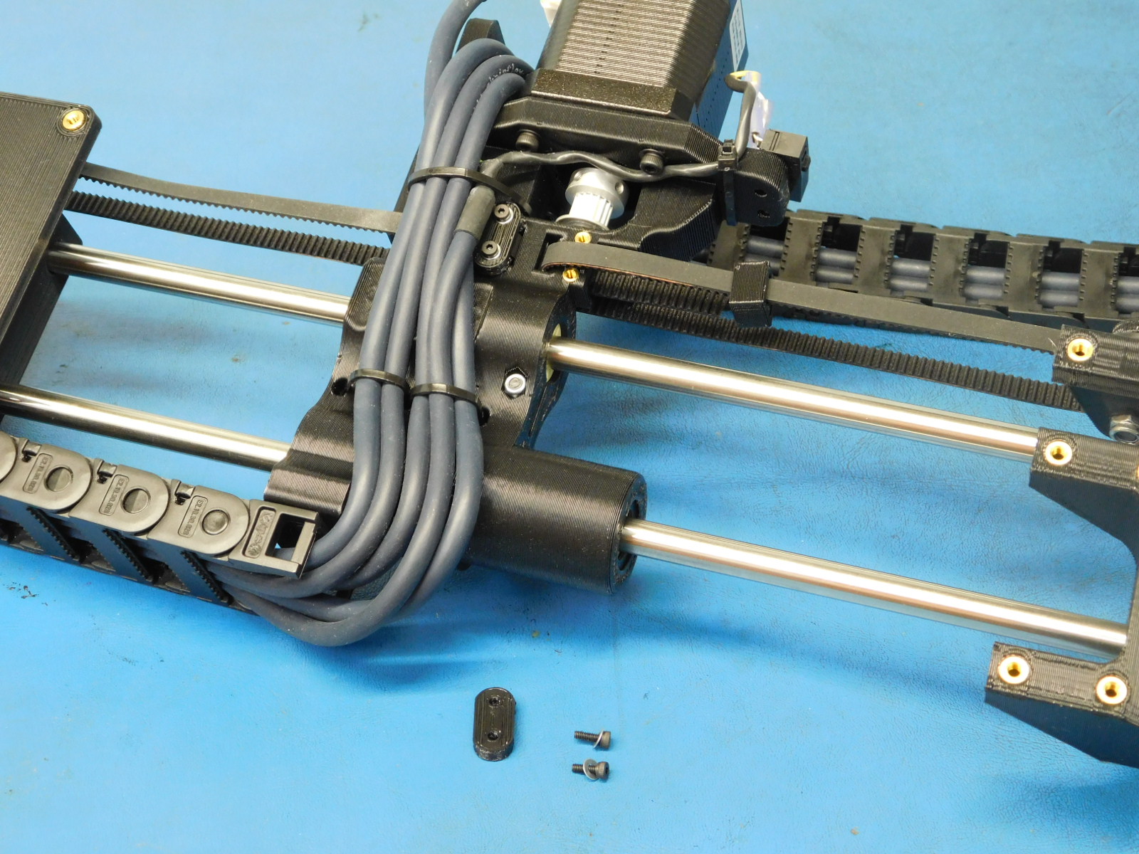
a) Attach the motor (with the connector oriented down toward the bottom of the X-End Motor assembly) to the X-End Motor assembly with 4x- M3x12 SHCS [HD-BT0039] with M3 washers [HD-WA0038], tighten screws in 8 in*lbs.
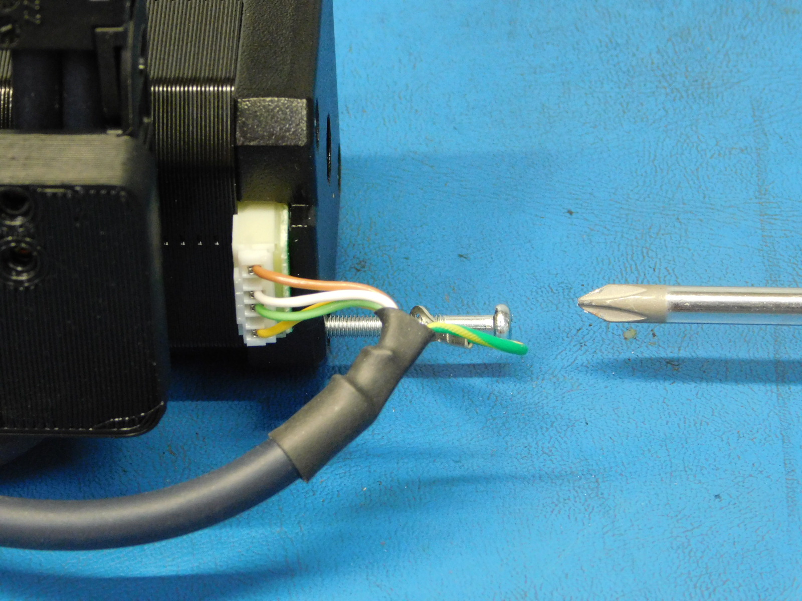
b) Remove the lower right phillips head screw from the back of the motor just installed, install the screw into the ring terminal from the X Motor cable, re-install the screw until the head is again recessed and tight.
c) Connect the JST connector to the motor as pictured.
d) Bend the z max switch connectors 90 degrees away from the x-end motor and obtain a zip tie HD-MS0058] and rough the zip underneath the connectors making sure to route it over the cable and in the specified groove of the x-motor part.
e) Ensure that all zip ties are cinched tight and clip all excess lengths.
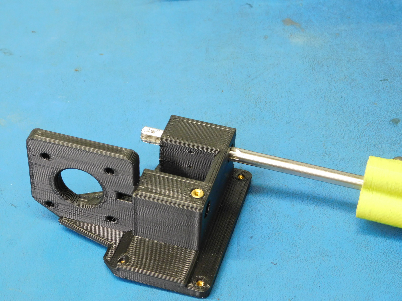
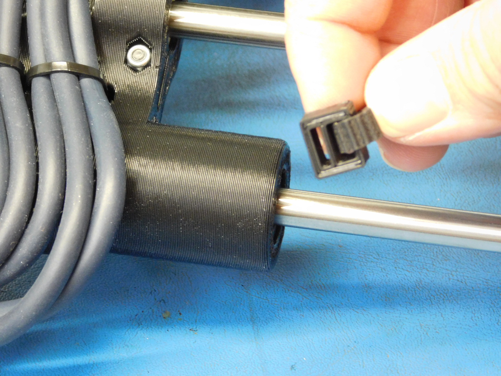
a) Install 2x smooth rods [HD-RD0035] into the x end motor sub-assembly.
b) Install bottom ends of the two smooth rods into the Z-Lower left.
c) Install top ends of the two smooth rods into the Z-upper right.

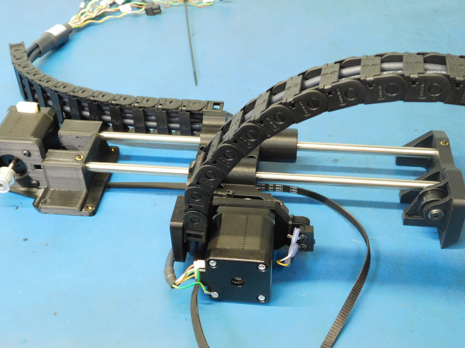
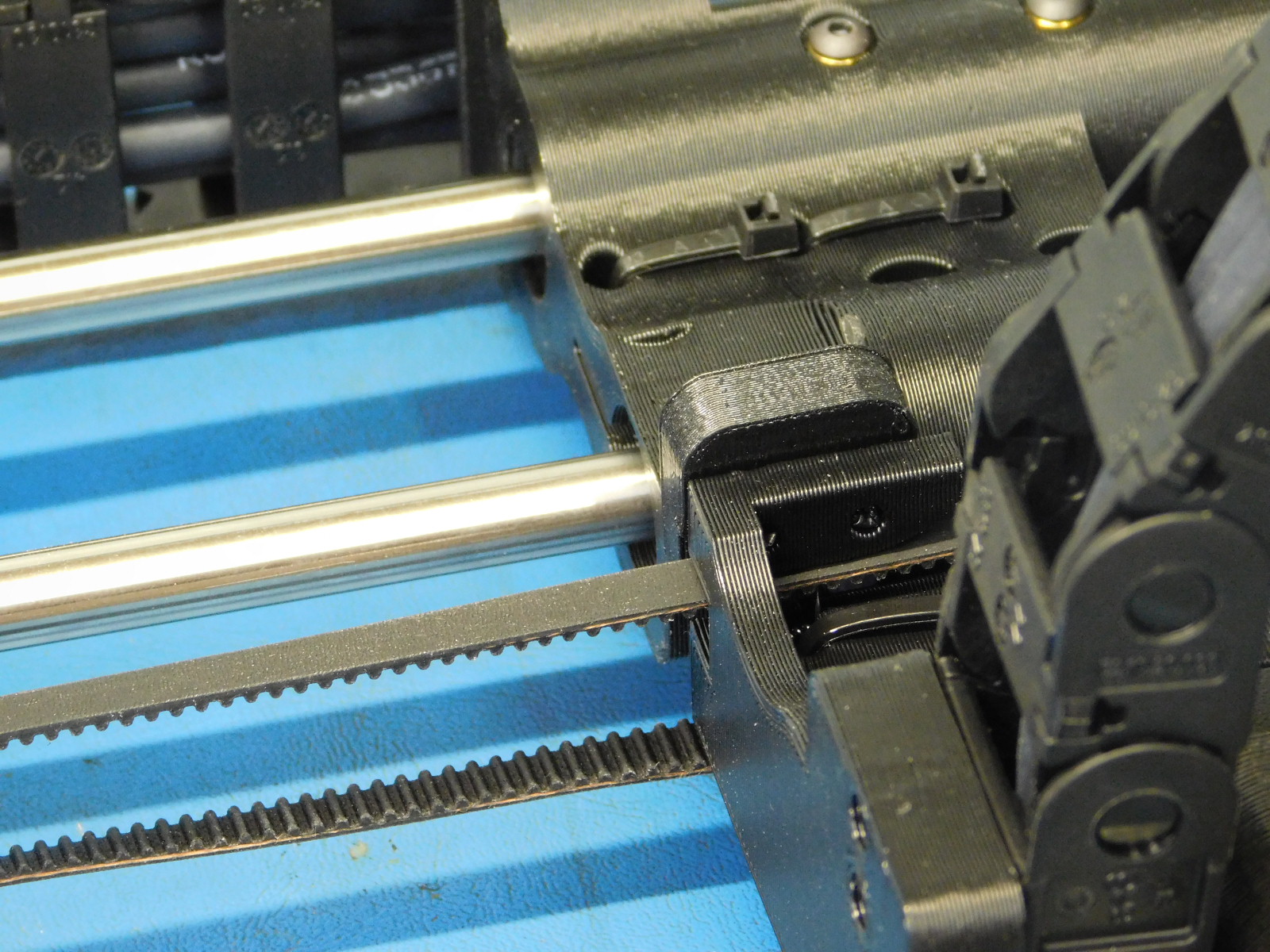
a) Route the belt down around the Z-Motor pulley and up through the hole in the X-End Motor mount [AS-PR0090]
b) Continue through the bearing in the Z-Upper Left [AS-PR0091] so that the belt makes a loop back to the X-End Motor without twisting.
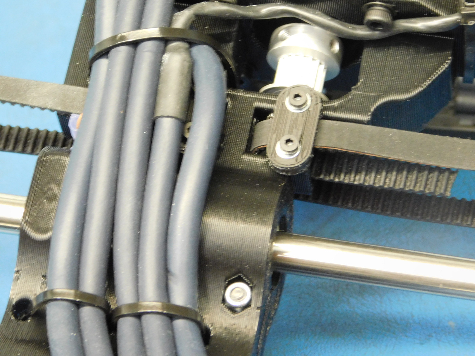
c) Install one Belt Tensioning Collar [PP-GP0307] onto the belt with the narrow end facing the Z-Upper Left Assembly [AS-PR0088] and the slack retaining side facing the inside of the printer.
d) Slide the belt through the upper slot of the Z-Belt clamping feature; Secure in place using one Z-Belt Clamp [PP-GP0308] with two M2x6 SHCS [HD-MS0230] with washers [HD-WA0012]
Lay the assembly flat against table and ensure that none of the wires are sitting against the table.