Open HardwareAssembly Instructions
Guides for installation and assembly of the LulzBot line of products made by Aleph Objects, Inc.
Guides for installation and assembly of the LulzBot line of products made by Aleph Objects, Inc.
Material list will be done later
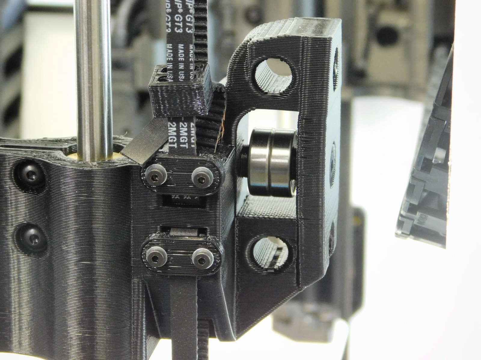
a) On the X-End Idler, loosen the upper Z-Belt Clamp using a 1.5mm Hex driver.
Grip the end of the belt above the X-End Idler and twist to apply tension to the Z-Belt.
Tighten the two M2x6 SHCS on the upper Z-Belt Clamp to secure the Z-Belt.
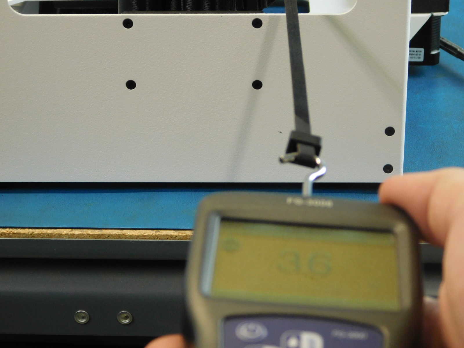
b) Use the 508C Sonic Tension Meter to ensure the belt is tensioned sufficiently.
Acceptable tension for the Z-Belts is 35-45N For proper measurement results, obtain measurements with the Z-axis near mid travel, ensuring the section of belt being measured is not contacting printed parts; this will provide incorrect tension readings.
Setting number 3 on your 508C Meter is set-up with proper parameters for the Z-axis, if unsure contact your line lead, supervisor, or MER Technician.
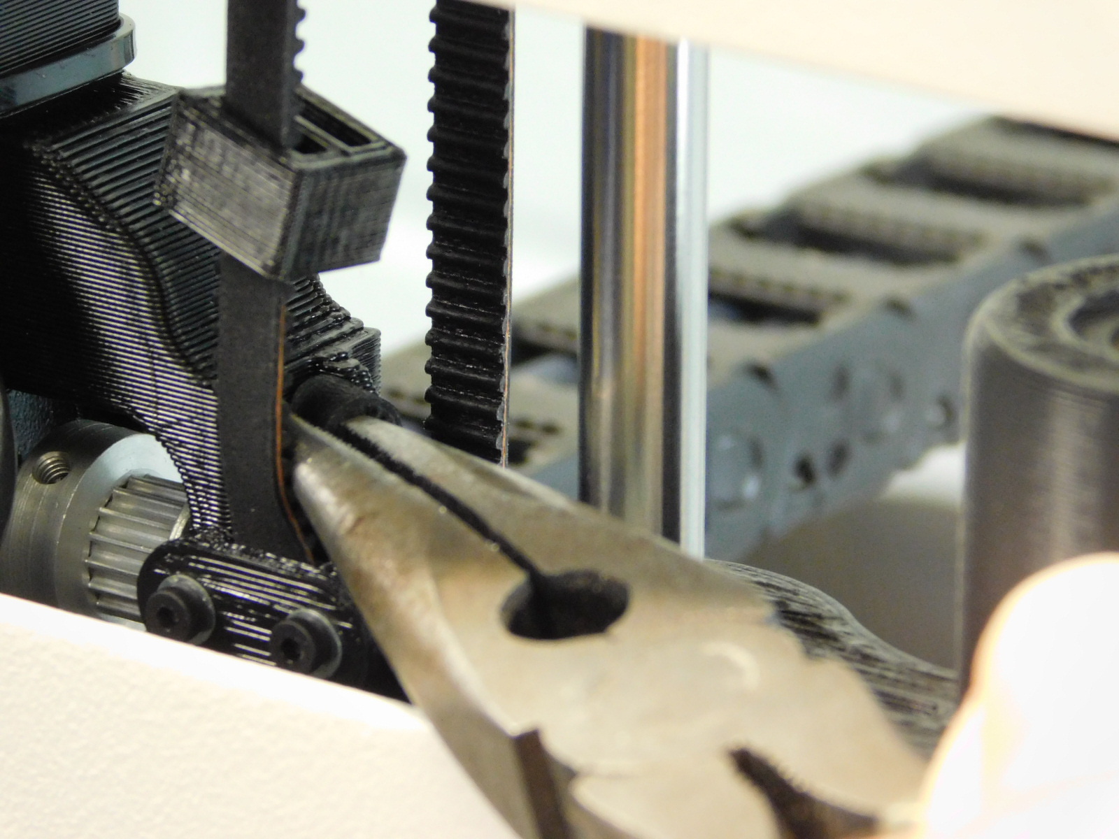
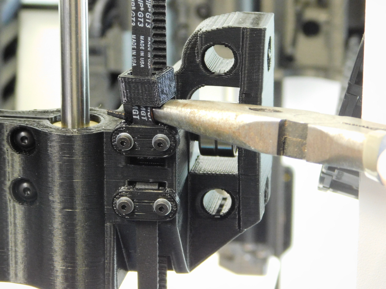
c) Slide the Belt Tensioning Collar [PP-GP0307] down over the end of the belt to capture the slack. Push it as close to the X-End Idler printed part as possible.
Trim the excess belt straight with the teeth of the belt, leaving ~5mm above the belt tensioning collar.
d) Repeat this process on the X-End Motor side;
Grip the bottom of the X-End Motor printed part and lift until the upper Z-Belt Clamp is visible through the cut-out in the left frame plate.
Loosen the two M2x6 SHCS securing the upper Z-Belt Clamp until the belt is able to move.
Grip the end of the belt on top of the X-End Motor printed part and twist to apply tension to the Z-Belt.
Tighten the two M2x6 SHCS on the upper Z-Belt Clamp to secure the Z-Belt.
e) Slide the Belt Tensioning Collar [PP-GP0307] down over the end of the belt to capture the slack. Push it as close to the X-End Motor printed part as possible.
Trim the excess belt straight with the teeth of the belt, leaving ~5mm above the belt tensioning collar.
f) Use the 508C Sonic Tension Meter to ensure the belt is tensioned sufficiently.
Acceptable tension for the Z-Belts is 35-45N. It is best to set the belt towards the top of the range, because they will settle to a lower tension after burn-in. For proper measurement results, obtain measurements with the Z-axis near mid travel, ensuring the section of belt being measured is not contacting printed parts; this will provide incorrect tension readings.
Setting number 3 on your 508C Meter is set-up with proper parameters for the Z-axis, if unsure contact your line lead, supervisor, or MER Technician.
Both Z-Belts should be as close to each other in tension as possible.
Torque Z-Belt Clamp fasteners to 2in*lbs

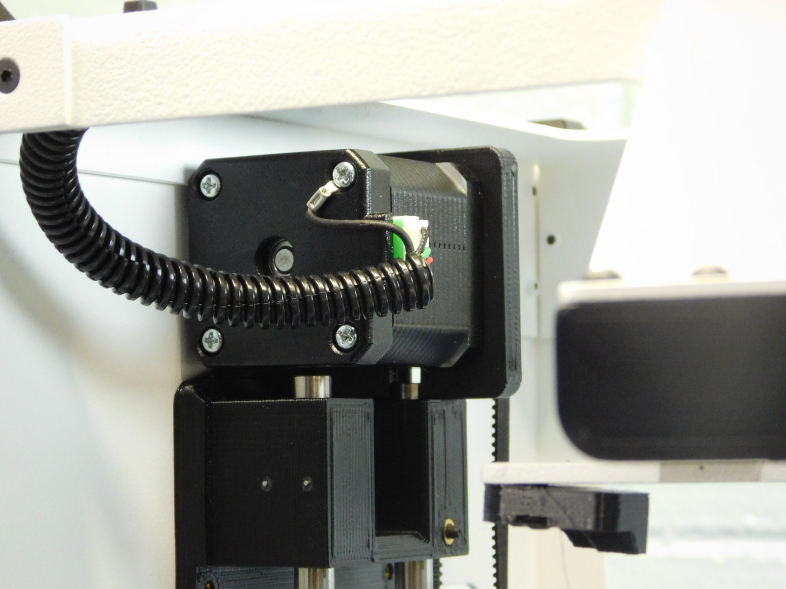
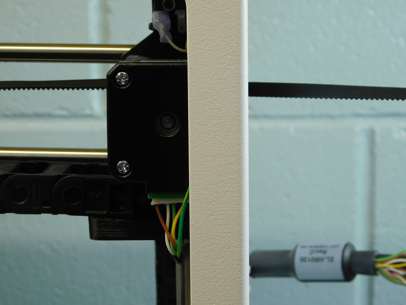
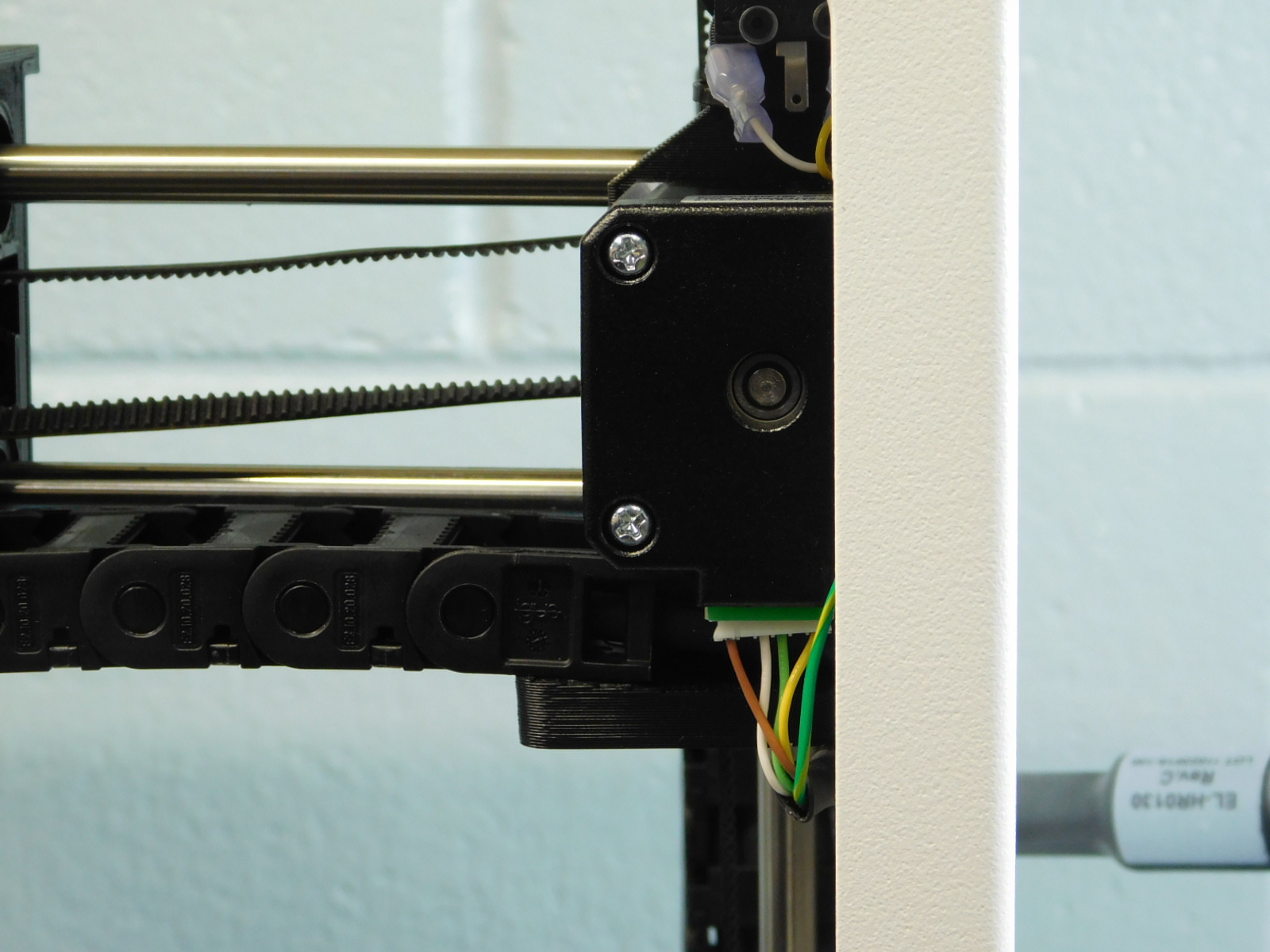
a) Completely remove the Z-Right motor housing screw below the connector using a P2 Phillips screwdriver
b) Insert the right motor's housing screw through the ring terminal of the Z-Right Motor cable, reinstall the housing screw into the Z right motor capturing the ring terminal.
Ensure the screw becomes recessed and tight.
Connect the JST connector to the Z-Right Motor
c) Completely remove the Z-Left motor housing screw below the connector using a P2 Phillips screwdriver
d) Insert the left motor's housing screw through the ring terminal of the Z-Left Motor cable, reinstall the housing screw into the Z-Left motor, capturing the ring terminal.
Ensure the screw becomes recessed and tight.
Connect the JST connector to the Z-Left Motor
a) Flip the assembly back upright with the back of the machine facing you.
b) Use a 8mm part reaming tool to ream the smooth rod holes of the X-End Idler.
c) Push both Left & Right X-Ends down against the Z-Lowers so that they are level with each other.
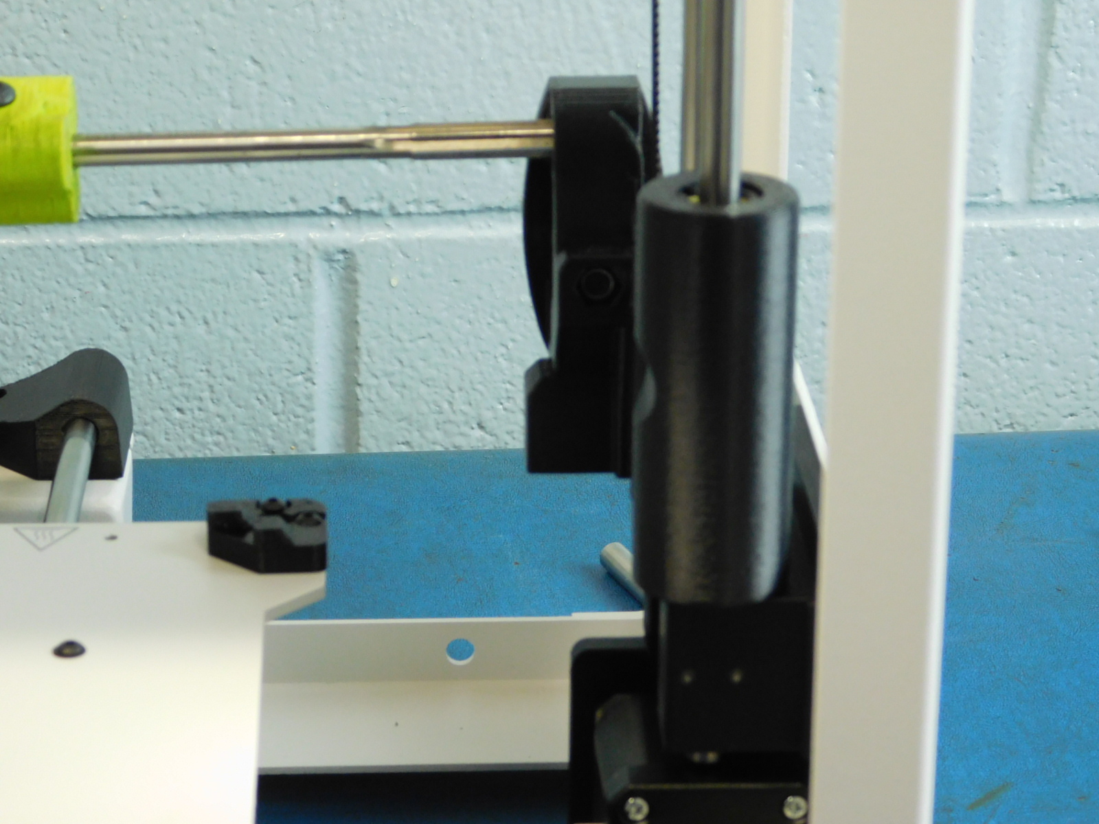
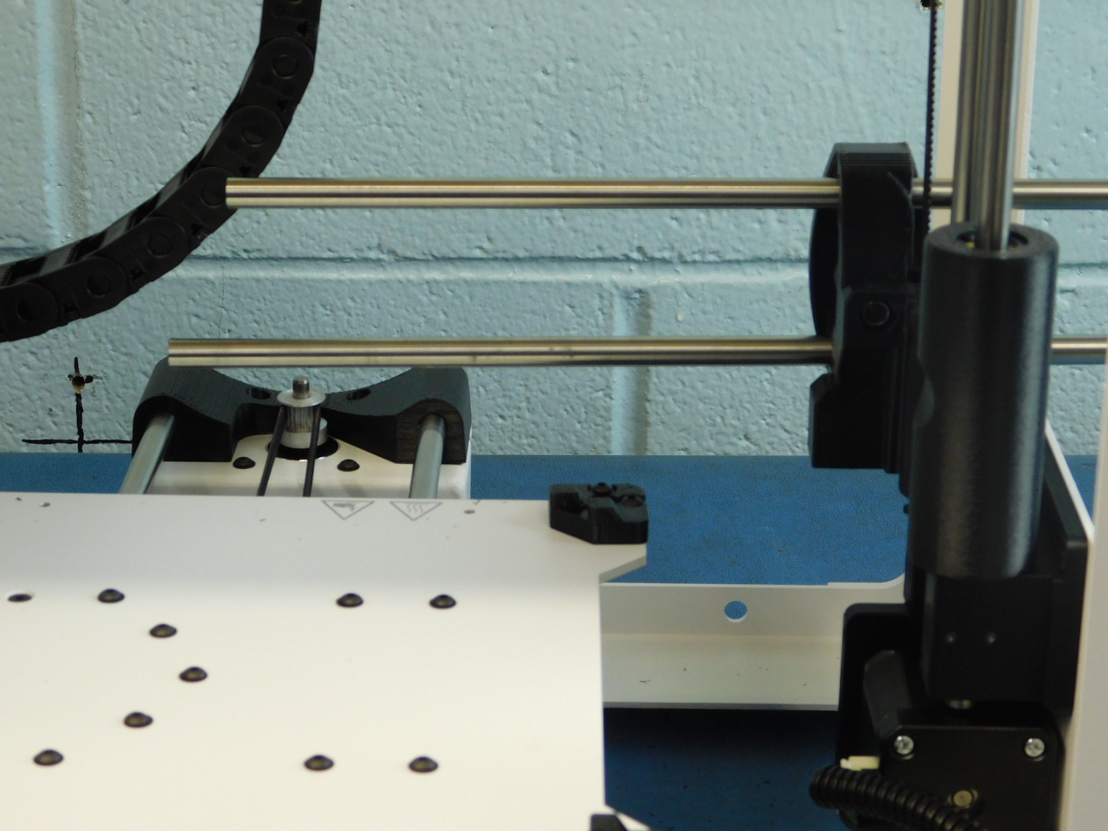
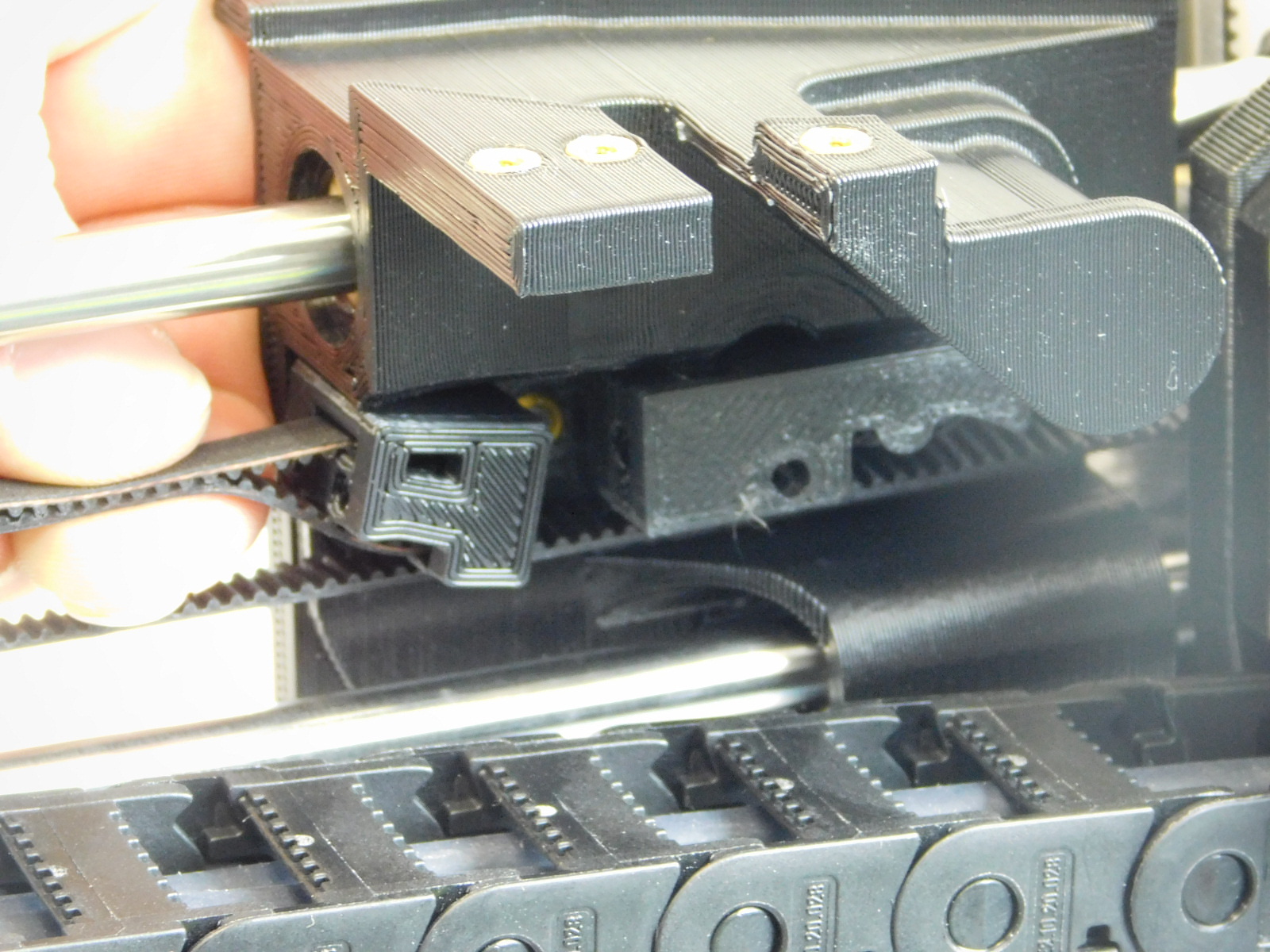
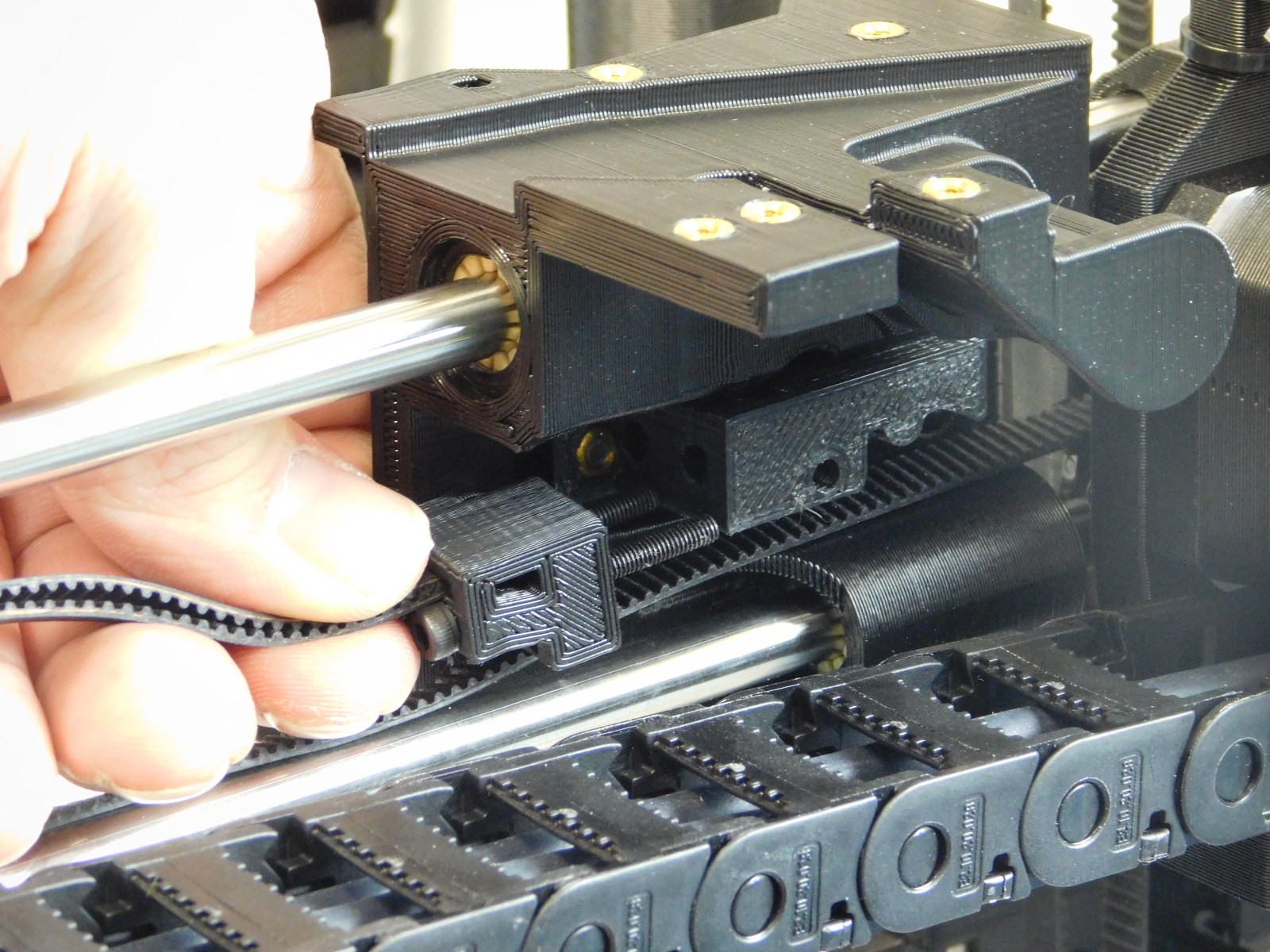
d) Slide the two smooth rods through the X End idler assembly and the X carriage assembly as pictured
e) Insert the ends of the Smooth Rods into the X-End Motor assembly
It is important not to push too far as too much distance between the X-Ends will cause the Z-Axis to bind at the top. Make sure the X-Ends remain relaxed with no outward tension from the Smooth Rods. The ends of the smooth rods should protrude an even distance from the right side of the X-End Idler printed part.
f) Tighten the set screws already installed in the rear of the X-End Idler; torque to 3in*lbs
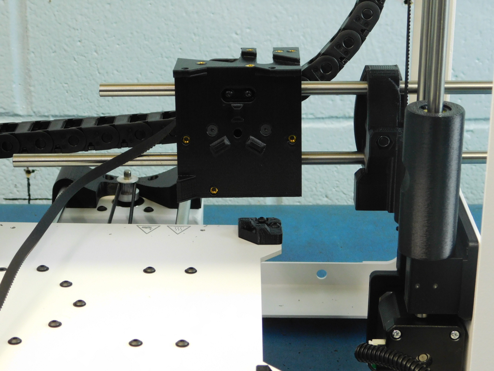
g) Using a 2mm Hex Driver, remove the four M3x8 BHCS securing the X-Bearing Holder to the X-Carriage, slide the X-Bearing Holder to your left on the smooth rod.
Using an eyedropper, apply a small amount of Loctite® 425™ to the now exposed M3 inserts on the back of the X-Carriage.
Re-install all four of the M3x8 BHCS with washers [HD-BT0137] & [HD-WA0038]
Torque all of these fasteners to 3in*lbs
h) Measure the drag of the x-carriage making sure the the peak drag does not measure above 15N and record the result in the x-carriage drag spec sheet.
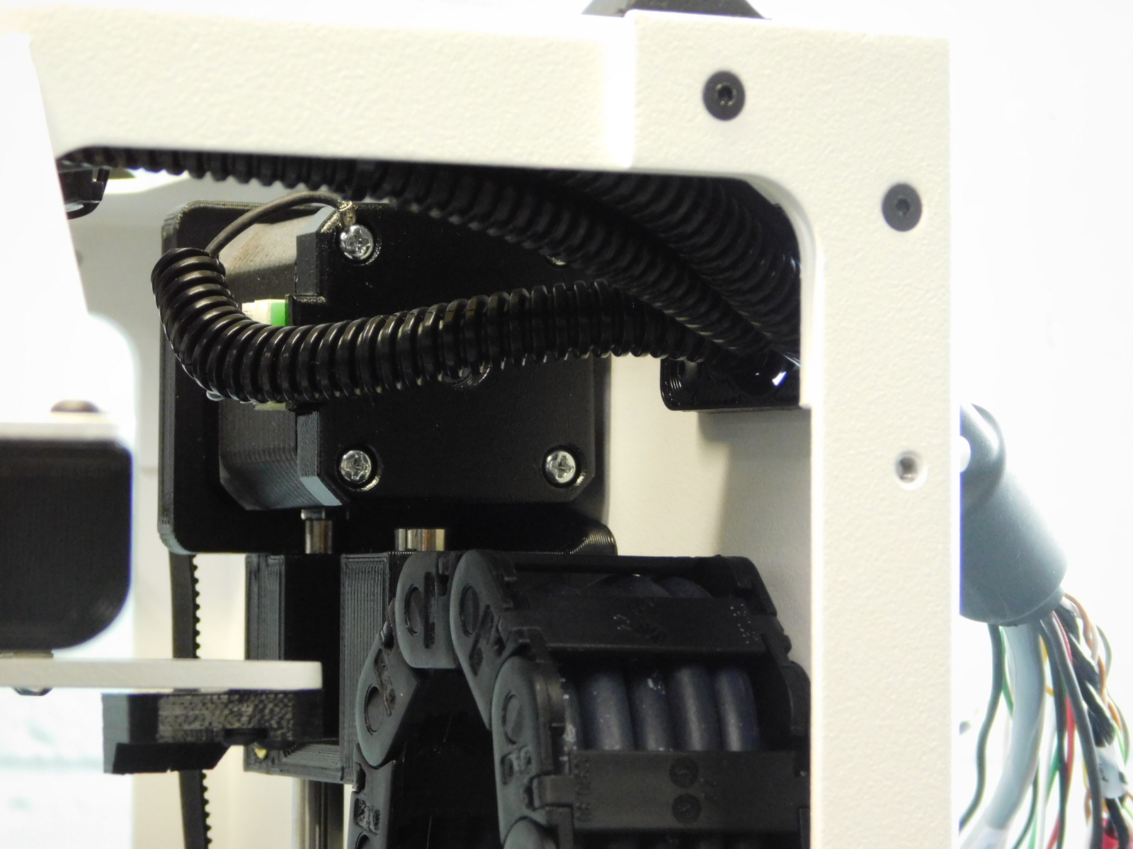
i) Remove the zip tie from the end of the cable chain.
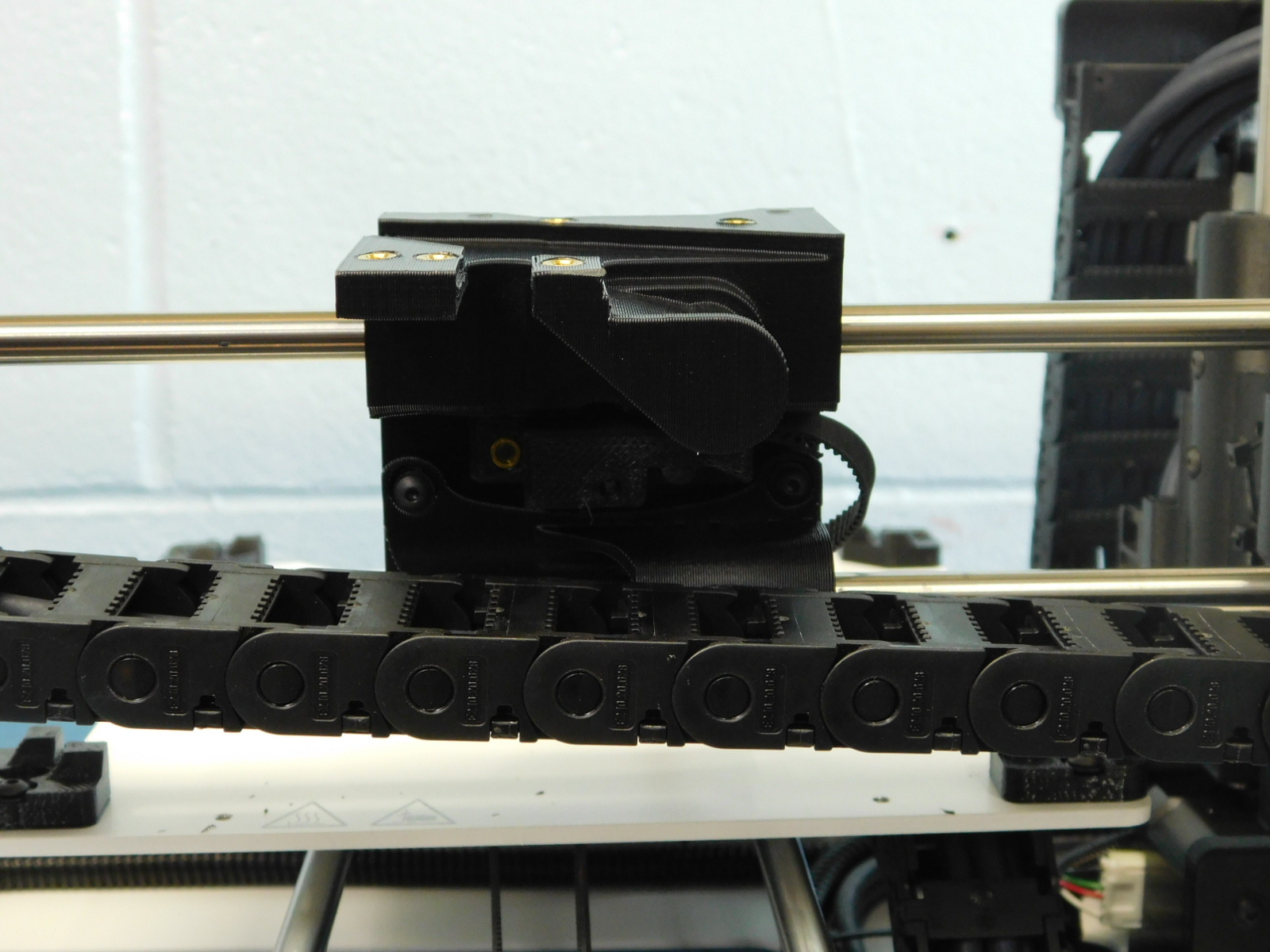
Remove the cable chain mount from the cable chain and attach to the X-Carriage as pictured using two M3x6 FHCS [HD-BT0128]
Re-attach the cable chain to the mount as pictured.
Write further instructions when have pictures

Write instructions when have pictures