Open HardwareAssembly Instructions
Guides for installation and assembly of the LulzBot line of products made by Aleph Objects, Inc.
Guides for installation and assembly of the LulzBot line of products made by Aleph Objects, Inc.
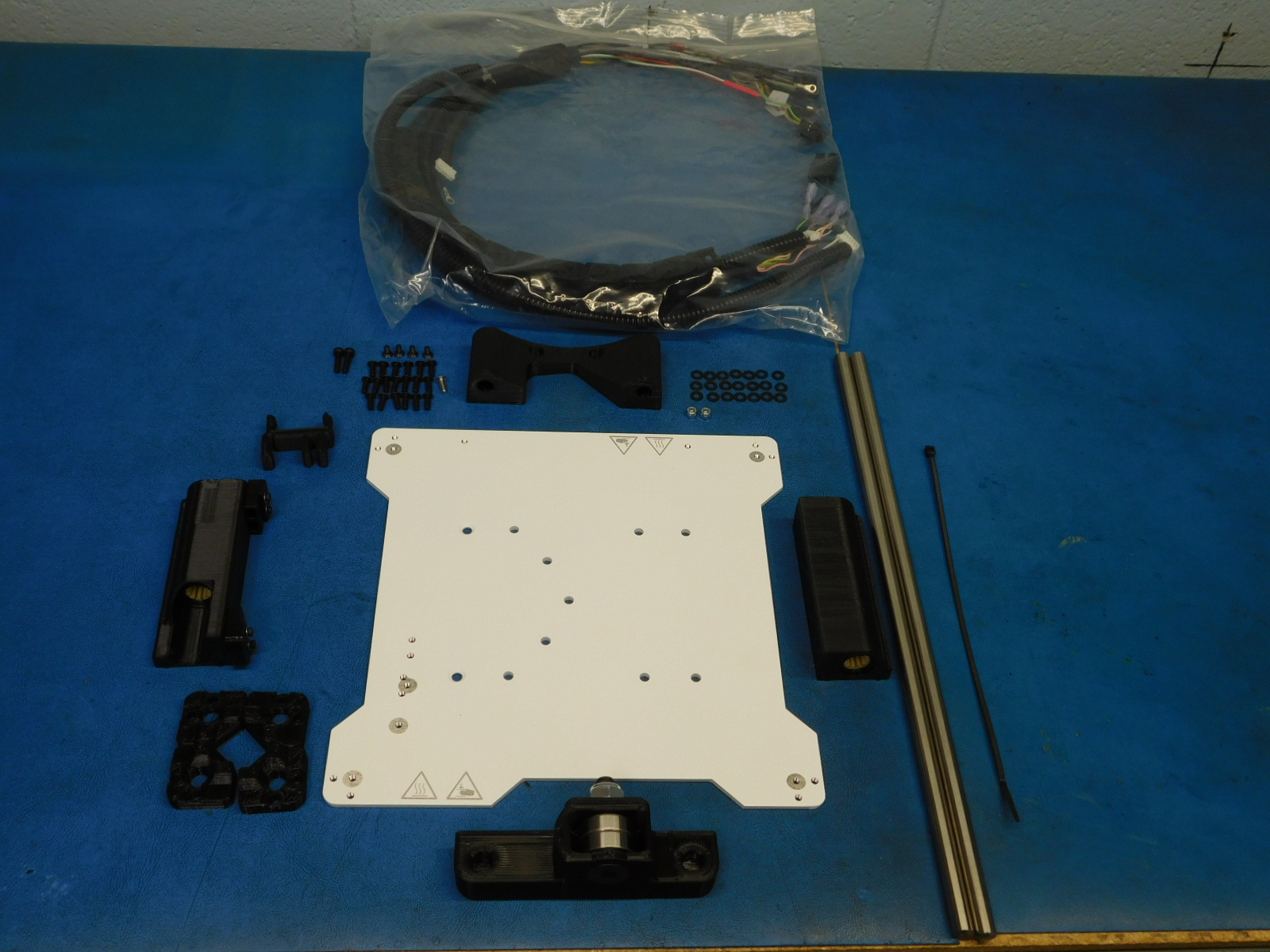
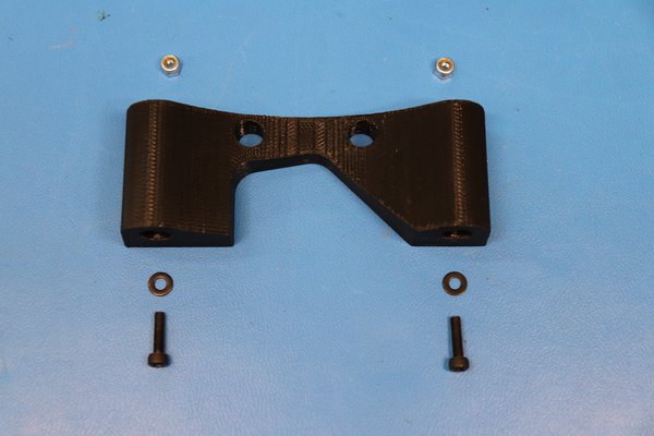
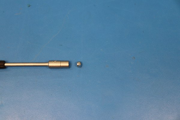
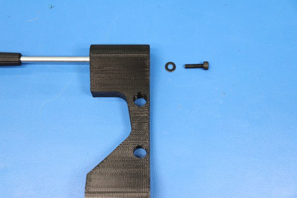
a) Put the M3 nyloc nut [HD-NT0001] into the 5.5 mm nut driver.
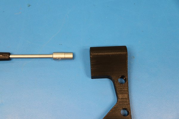
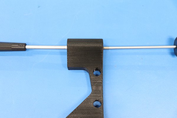
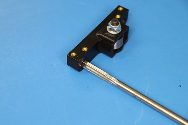
b) Insert the 5.5mm nut driver in to the Y-Rod Mount with the ".5" on the nut driver facing the top of the printed part, this ensures proper alignment of the nyloc nut. Make sure you press the driver to the bottom of the bore. Then, use a M3 x 12 SHCS [HD-BT0039] and an M3 washer [HD-WA0038] to pull the nyloc into the hexagon shaped hole in the printed Y-Rod Mount [PP-IS0064] with a 2.5 mm hex driver or electric screwdriver.
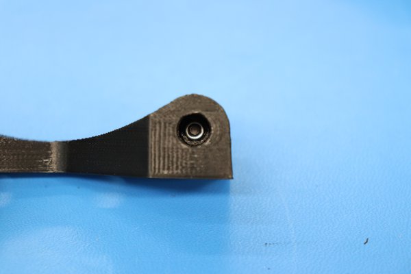
c) Inspect the nyloc nut to make sure it is seated into the nut trap correctly.
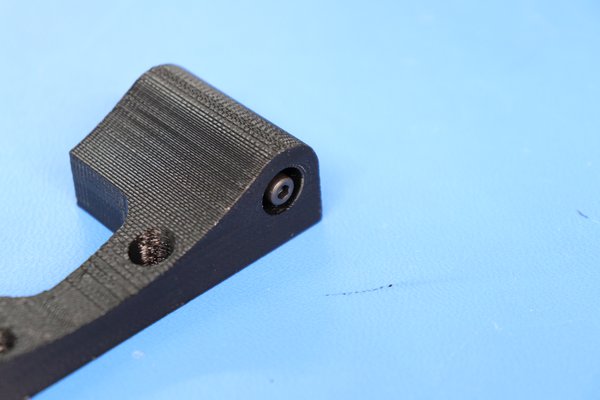
d) Back the screw out until it is flush with the printed part.
e) Repeat this process for the other side of the printed part.
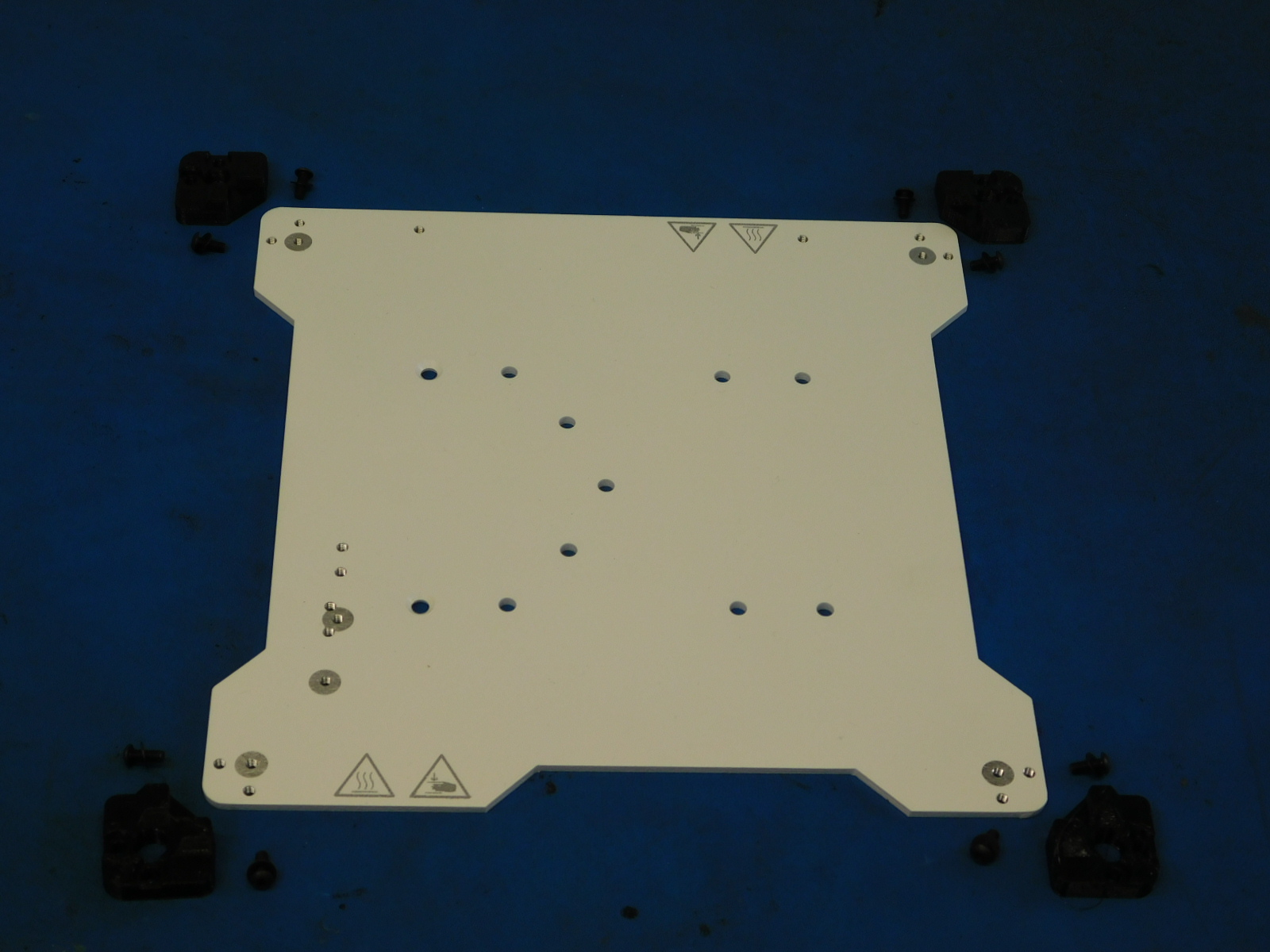
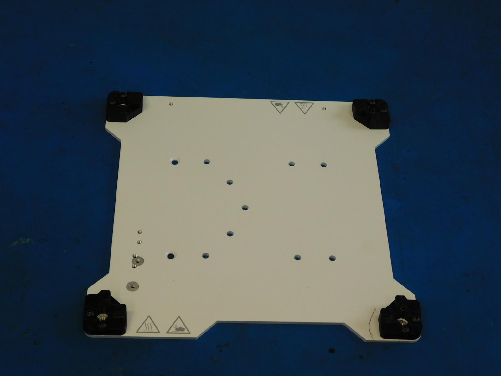
Using M3 x 10 BHCS [HD-BT0148] and M3 washers [HD-WA0038] fasten the urethane bed corners [PP-GP0477] to the white bed plate [PP-FP0171] with a 2 mm hex driver. These may be left loose for the time being; they will be tightened in position with the bed heater at Calibration.
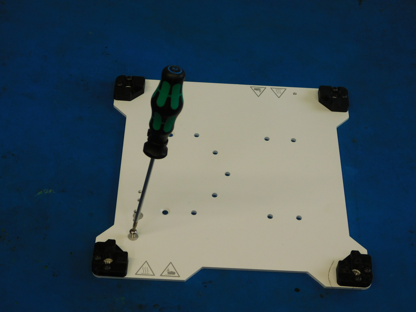
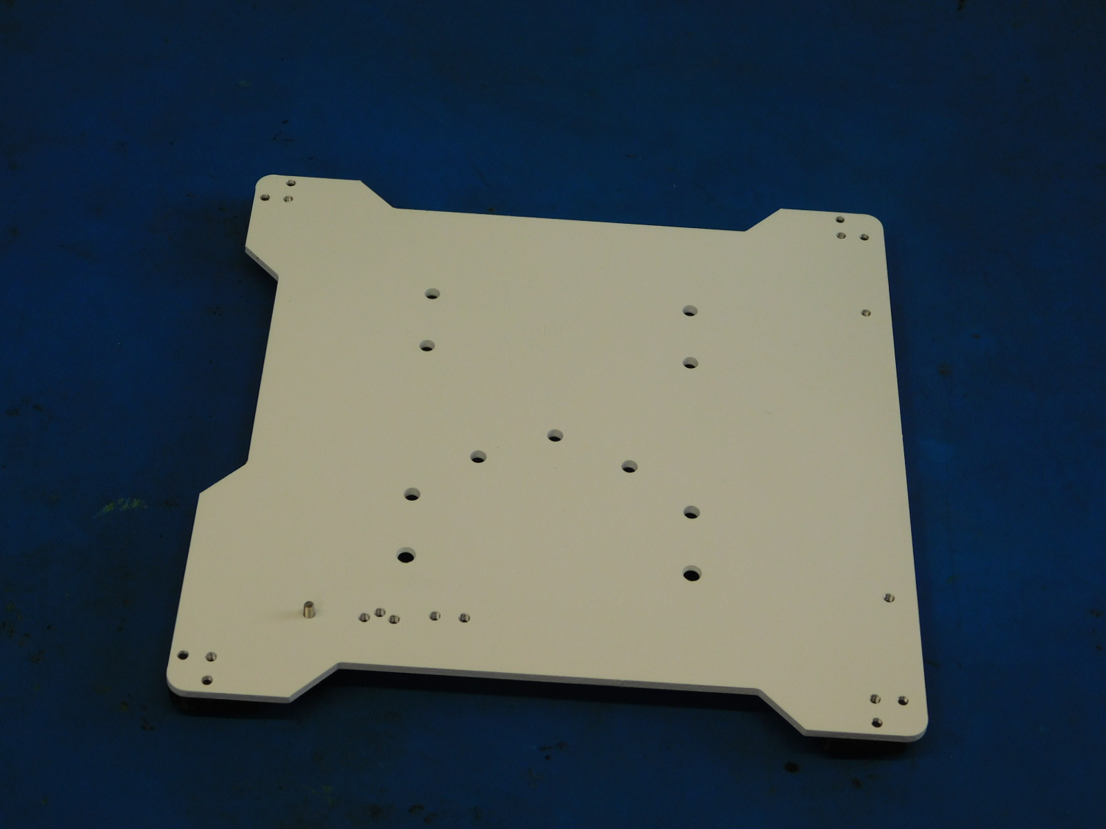
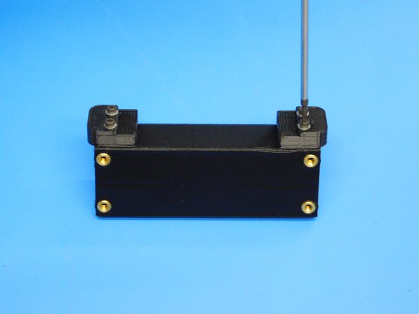
Install the M3 x 8 stainless steel BHCS [HD-BT0104] into the threaded hole towards the bottom left of the bed plate as pictured.
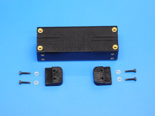
Using M2 x 10 SHCS [HD-BT0107] and M2 washers [HD-WA0012] fasten the urethane bumpers [PP-GP0332] to the single bearing assembly [PP-IS0073] with a 1.5 mm hex driver.

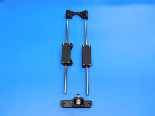
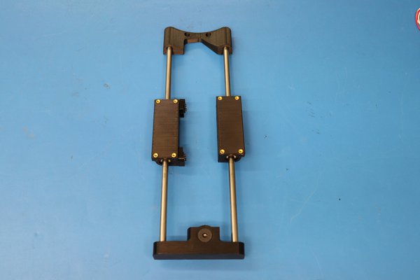
Slide the bushing assemblies [PP-IS0073] and [PP-IS0066] onto the 8 mm smooth rods [HD-RD0035].

a) Use the 8 mm reamer tool [TL-PW0225] to gently ream the y idler assembly [AS-PR0068] by continuously turning in a clockwise rotation. Take care to keep the tool straight and to not remove too much material which would result in a loose fitting rod.
b) Take note of the orientation of the bearing holders shown in the picture, then slide the smooth rods into the y idler assembly until they are fully seated. If they do not seat, it might be a sign that the reamer tool needs to be used to clean up the diameter of the blind hole in the printed part. Slide the other end of the rods into the motor side mount [PP-IS0064].
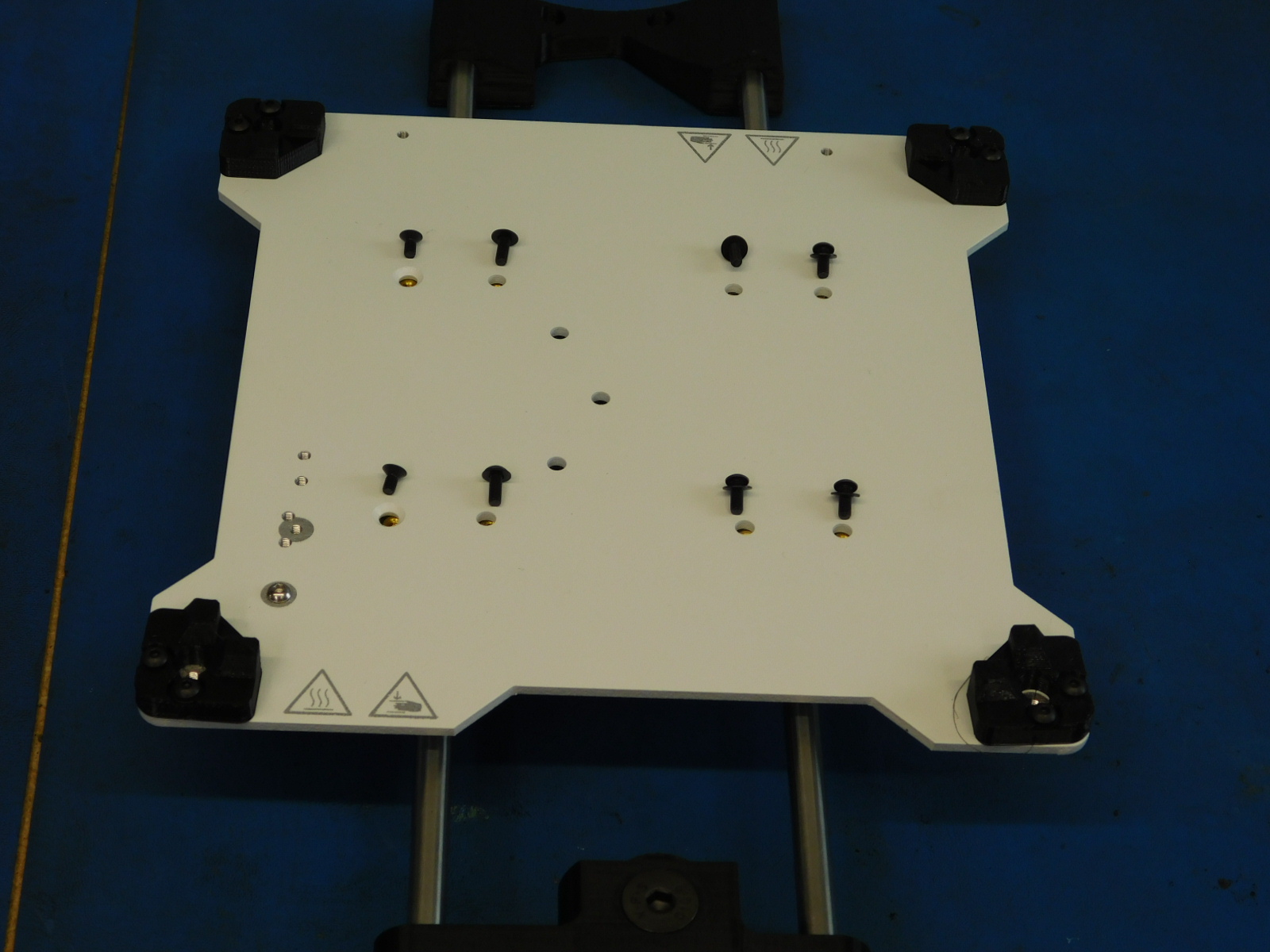
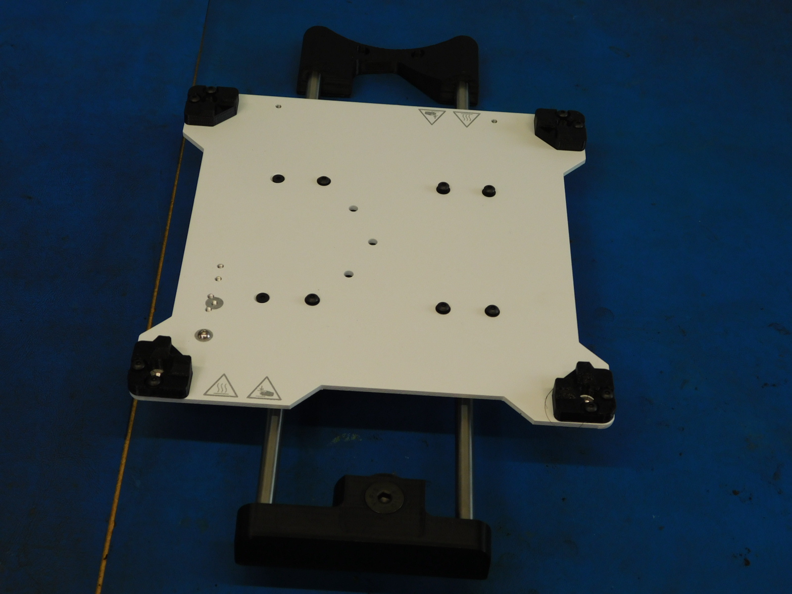
Using six M3 x 8 mm BHCS [HD-BT0137] and M3 washers [HD-WA0038] and two M3 x 6 mm FHCS [HD-BT0128] attach the bed plate assembly to the bearing holders.
These screws should be left loose for now, they will be tightened during Y-Axis Assembly to ensure proper alignment once the Bed Plate Assembly has been mounted to the Frame.
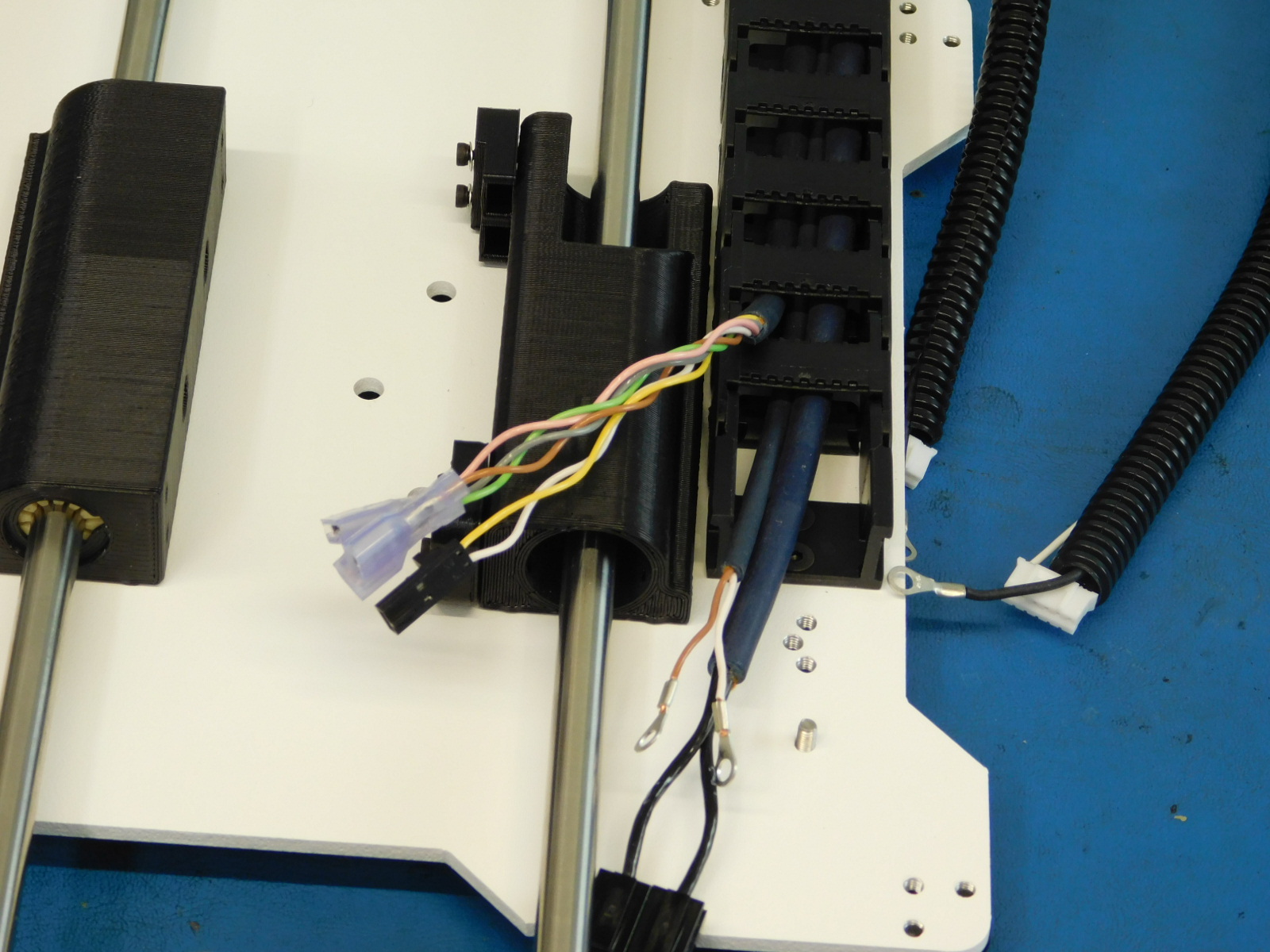
a) Place the Bed Plate Assembly plate side down onto the work station.
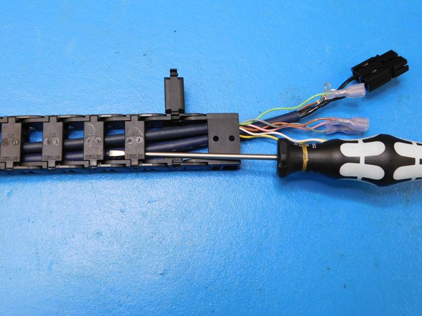
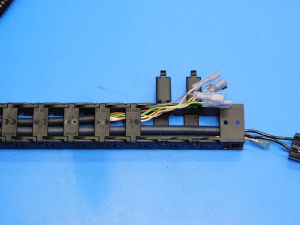
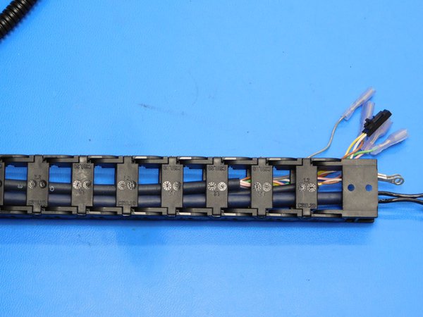
b) Route the Yellow/ White wire pair as well as the Green, Gray, Brown, and Pink wires through the last slot in the cable chain; using a standard screwdriver, open the last two backside access latches, send wires through the last slot in the top side of the chain, see [reference#1] , close the latches.
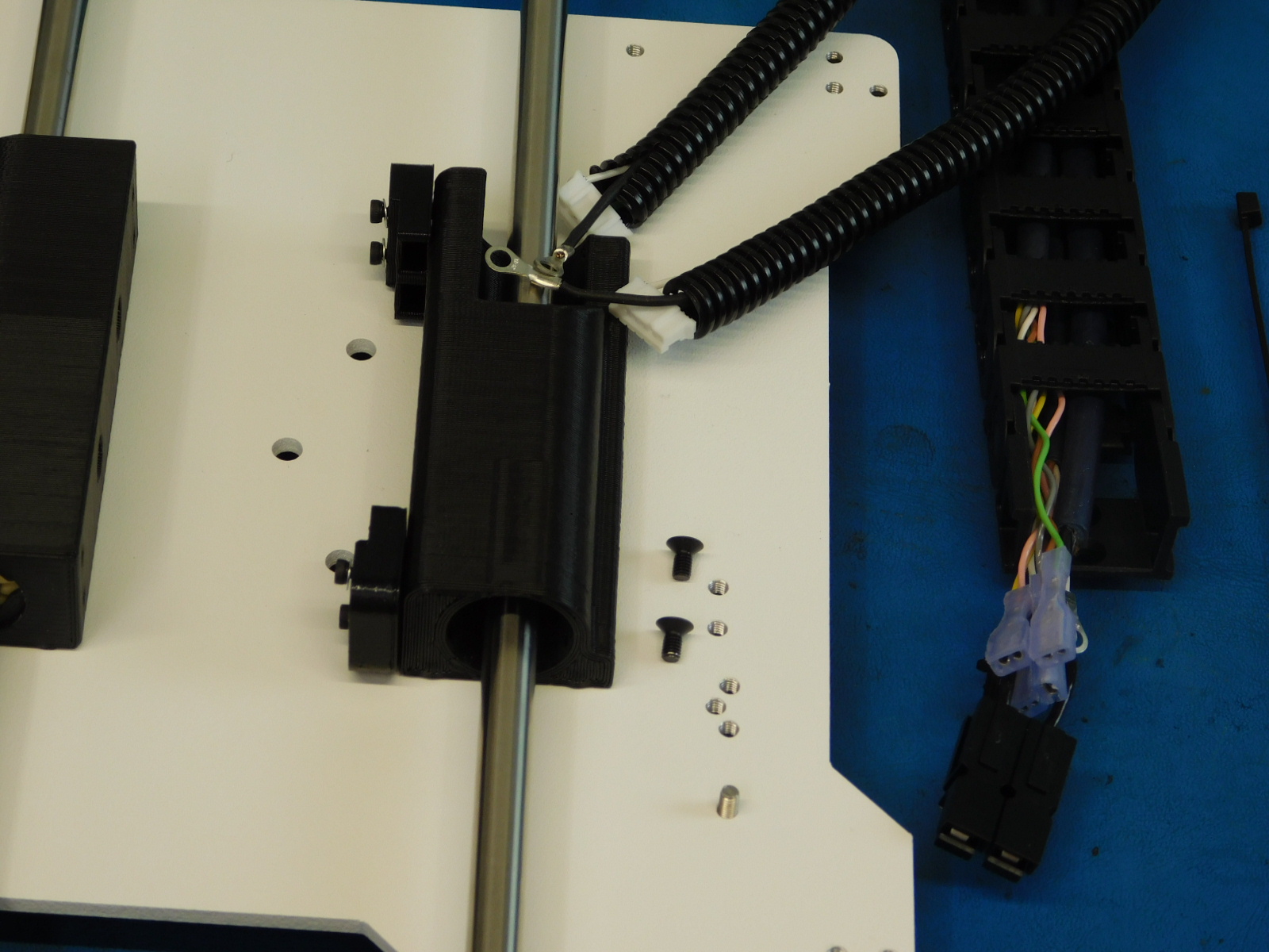
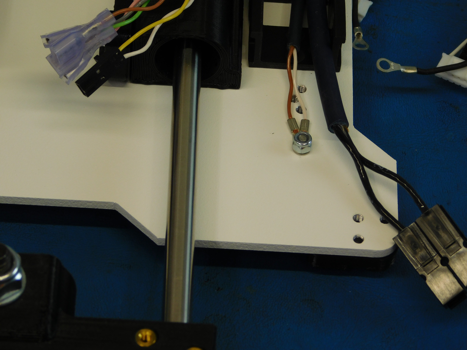
c) Attach AS-CB0071 (Bed Harness) to the Bed Plate Assembly with two M3x 6 FHCS [HD-BT0128], tightened to 5in*lbs.
d) Connect the two ring terminals from the cable harness to the screw, Secure the ring terminals to the screw with a M3 Nyloc nut [HD-NT0001] tighten until the ring terminals no longer move and the SS screw head remains flush and tight to the bed plate.
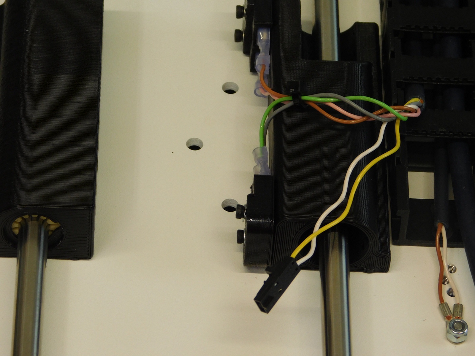
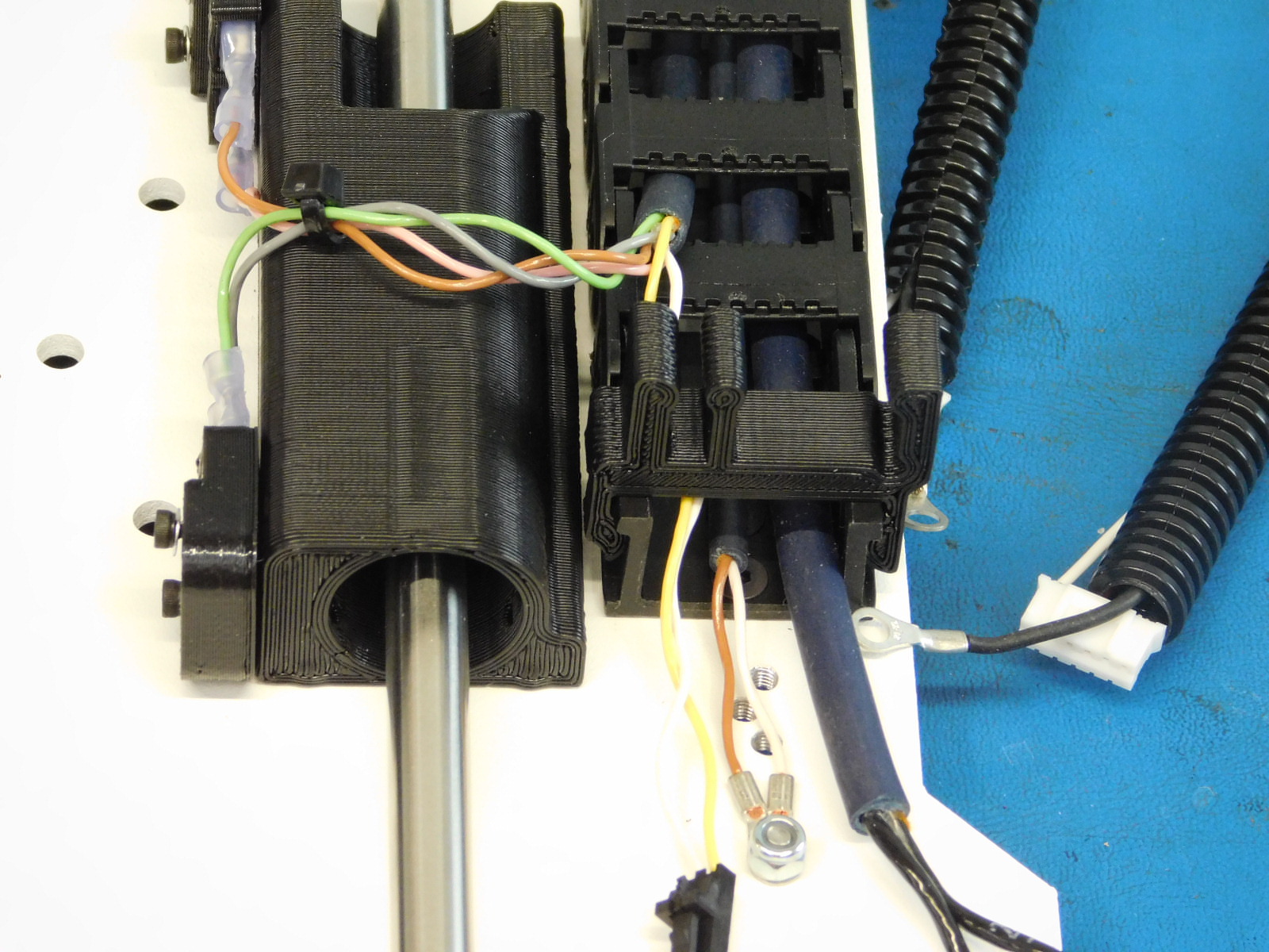
e) Insert the Green & Gray wires to the pockets on the rear of the Bump Stop on the front (idler side) and the Pink & Brown into the back (motor side) Bump Stop.
f) Tie the two pairs together with a cable tie with the cable tie.
e) Install the bed clip; there is a small notch out of one side of the latch, that notch faces the double bearing holder.