Open HardwareAssembly Instructions
Guides for installation and assembly of the LulzBot line of products made by Aleph Objects, Inc.
Guides for installation and assembly of the LulzBot line of products made by Aleph Objects, Inc.
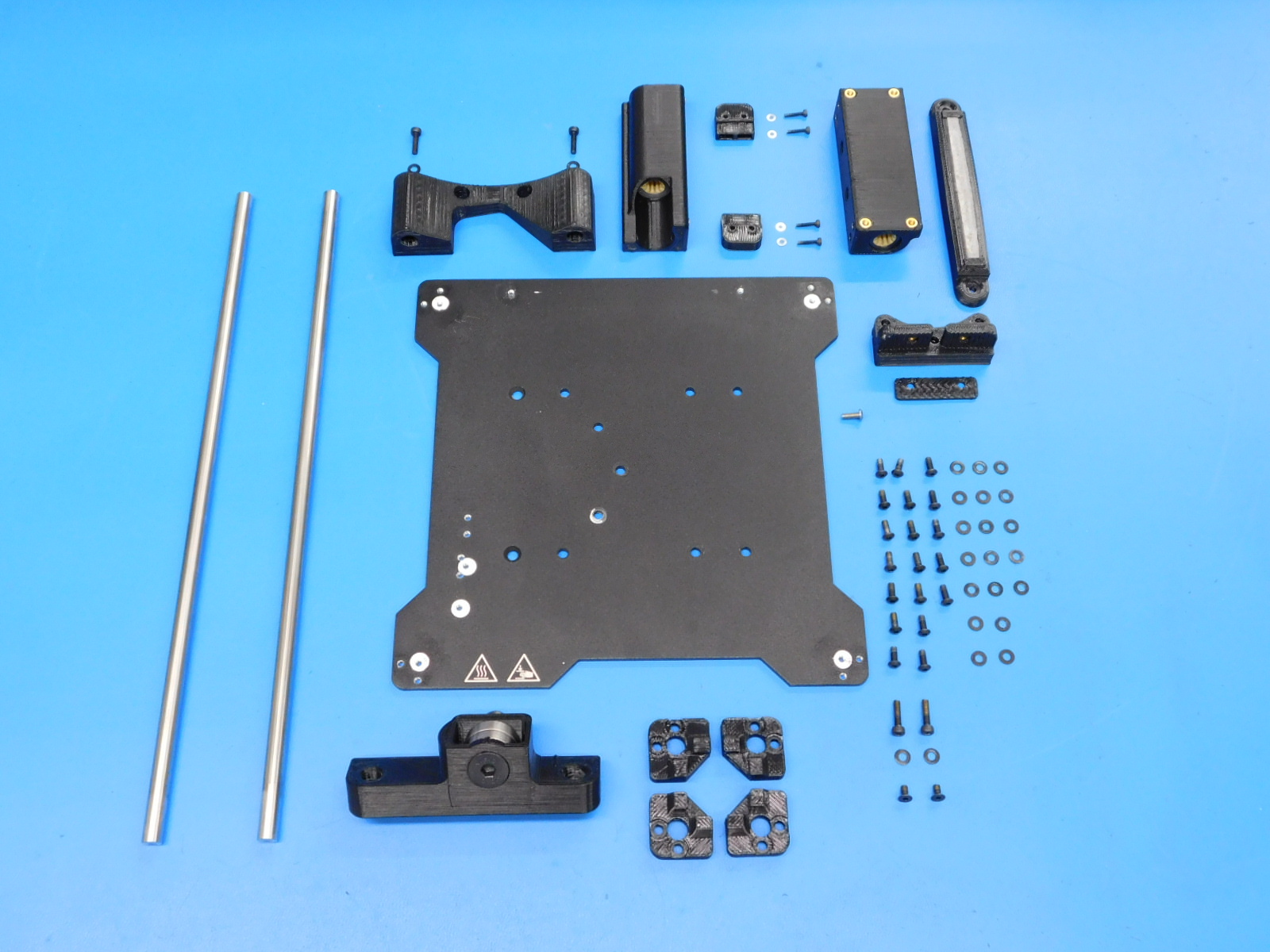
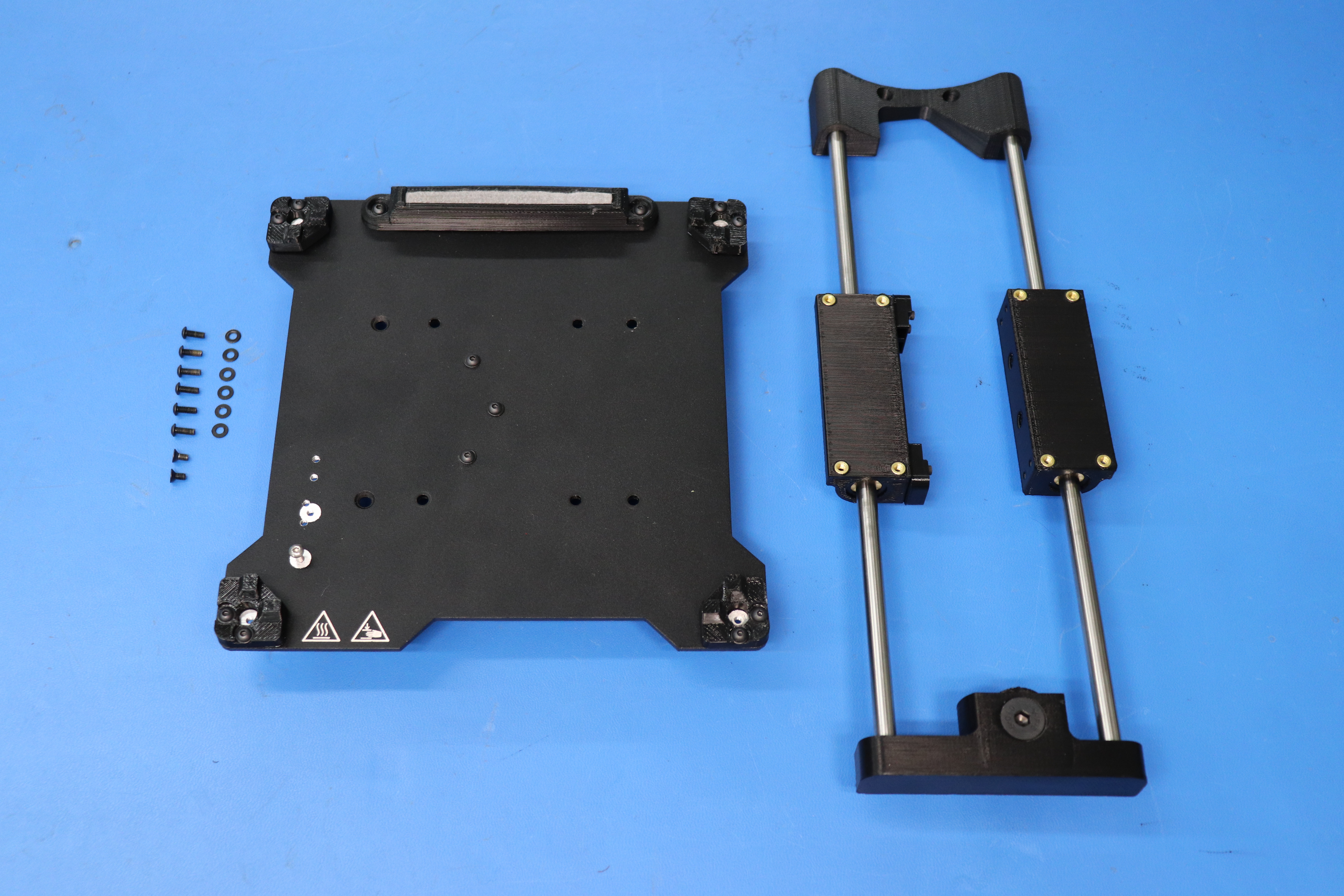
Gather the required materials:
1x- [PP-FP0138] Silk Screened Bed Mount Plate, Mini
1x- [PP-GP0231] Wiper Mount, v1.1
1x- [AS-PR0023] 90mm Cut wiper pad
1x- [PP-GP0278] belt-mount black v1.2
1x- [PP-GP0277] belt-clamp black v1.2
1x- [PP-IS0073] Mini 2 Single Bearing Holder with Inserts
1x- [PP-IS0066] Mini 2 Double Bearing Holder Non-Switch Side Insert Assembly
1x- [AS-PR0069] Mini, Y Axis Mount Idler Insert Assembly
1x- [PP-IS0064] Mini, Y Axis Rod Mount, Motor Side Assembly
2x- [PP-GP0332] Bump Stop
4x- [PP-GP0477] Flexy Bed Corner v2.2.4
2x- [HD-NT0001] Metric Zinc-Plated Steel Nylon-Insert Locknut
4x-[HD-BT0039] Metric Class 12.9 Socket Head Cap Screw
2x- [HD-RD0035] 8mm Smooth rod, 315mm, 300 Series Stainless Steel
4x- [HD-BT0107] Metric Class 12.9 Socket Head Cap Screw Alloy Steel, Black, M2 Thread, 10mm Length, 0.4mm Pitch
4x- [HD-WA0012] Steel Flat Washer, DIN 125 zinc-plated class 4,M2 screw sz, 5mm OD, .25mm-.35mm thick
8x- [HD-BT0148] M3 x 10 Bolt, BHCS, Black-Oxide
8x- [HD-BT0137] M3 x 8 Bolt, BHCS, Black-Oxide
14x- [HD-WA0038] Black-Oxide 18-8 Steel Flat Washer, M3 Screw Size, 3.2mm ID, 7.0mm OD
2x- [HD-BT0128] M3 x 6 Bolt, FHCS Black-Oxide
1x- [HD-BT0104] M3 x 8 Bolt, BHCS, SST
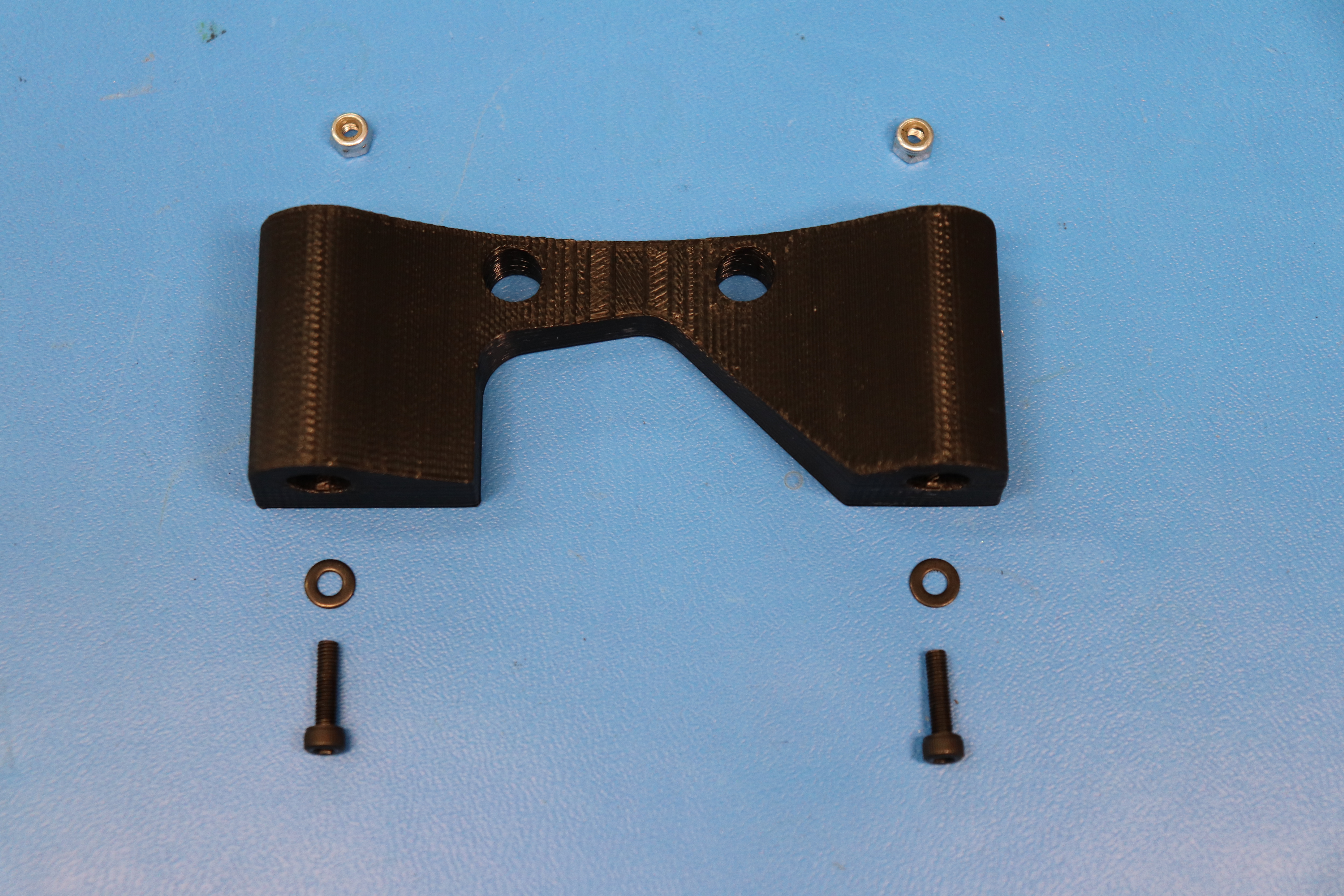
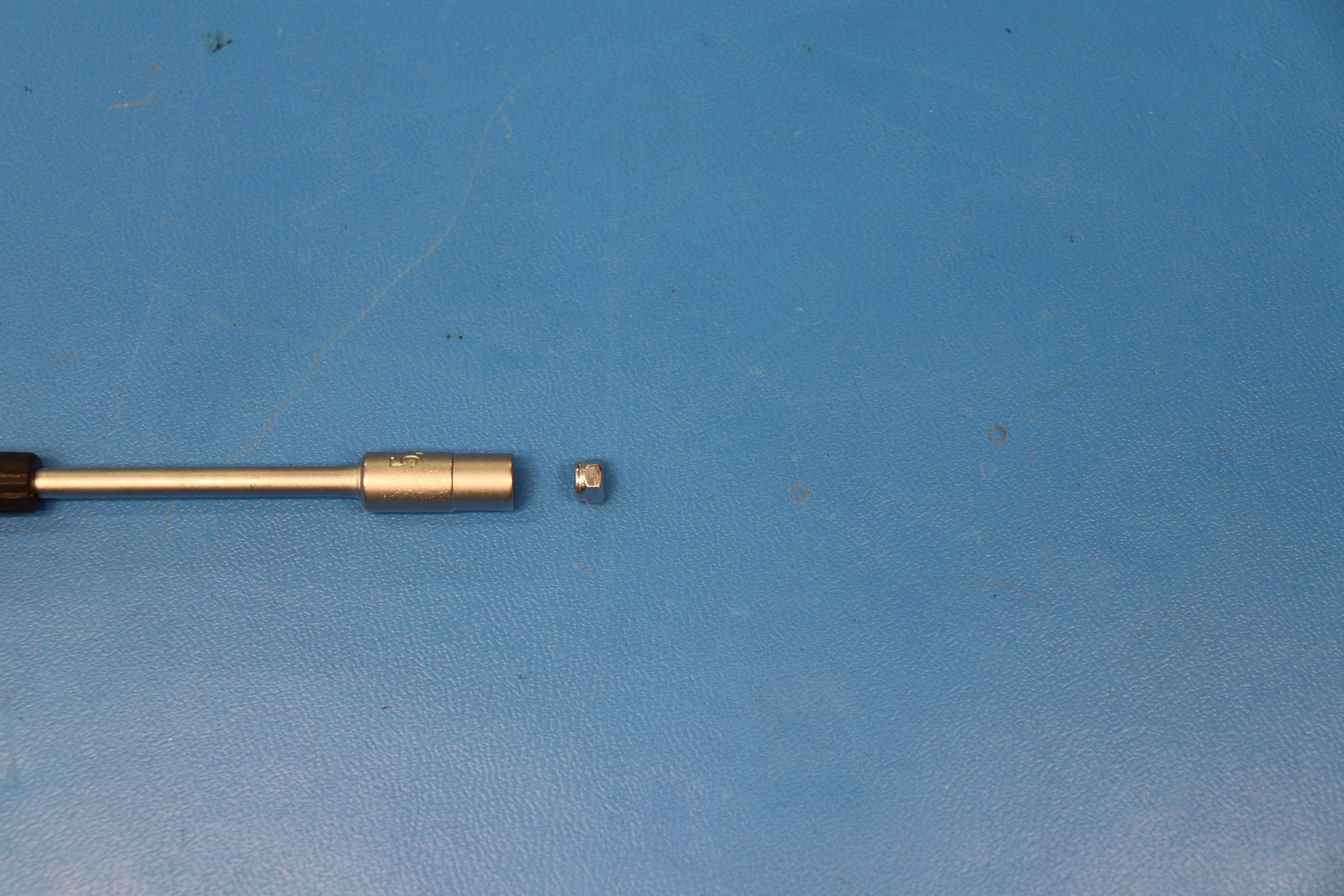
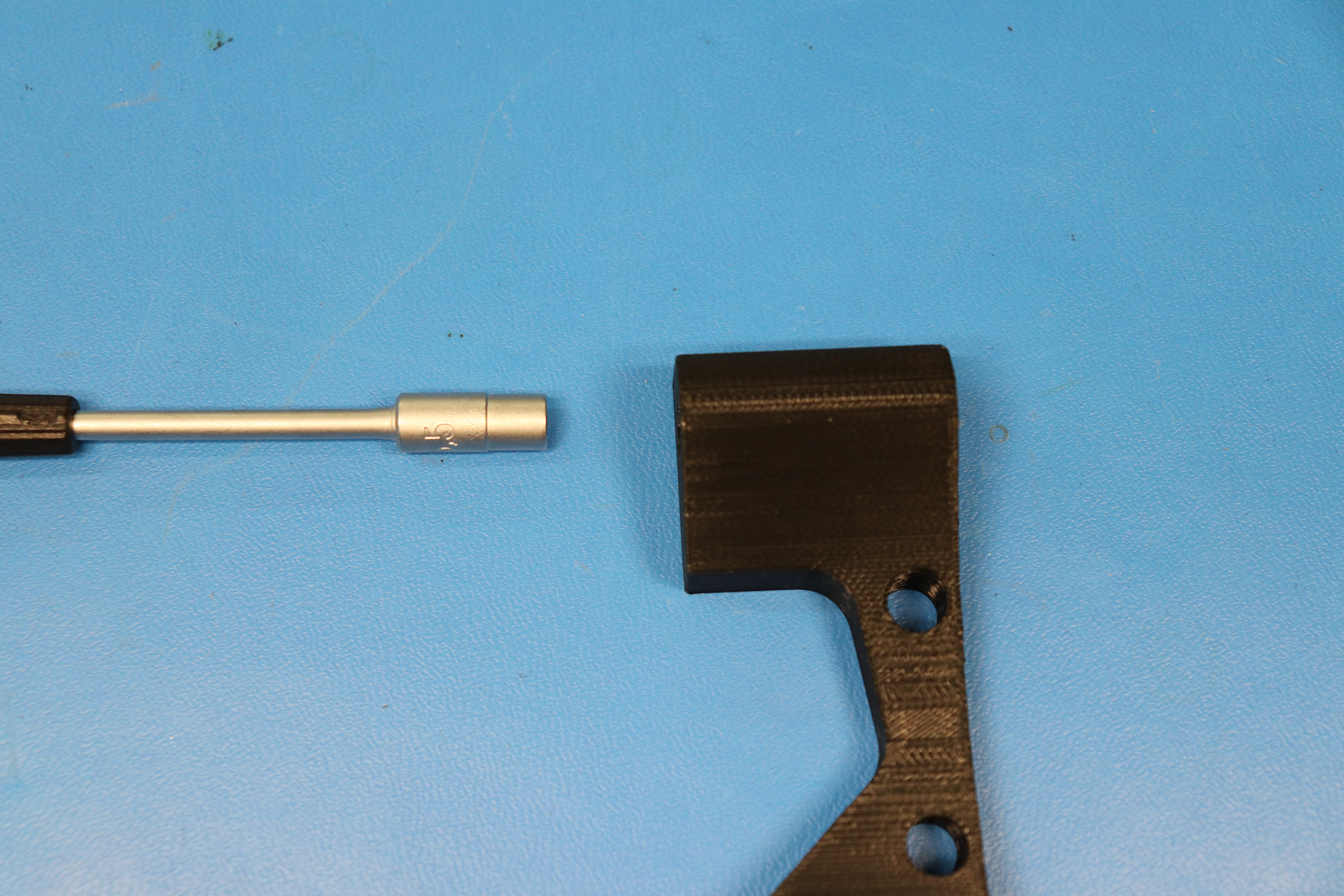
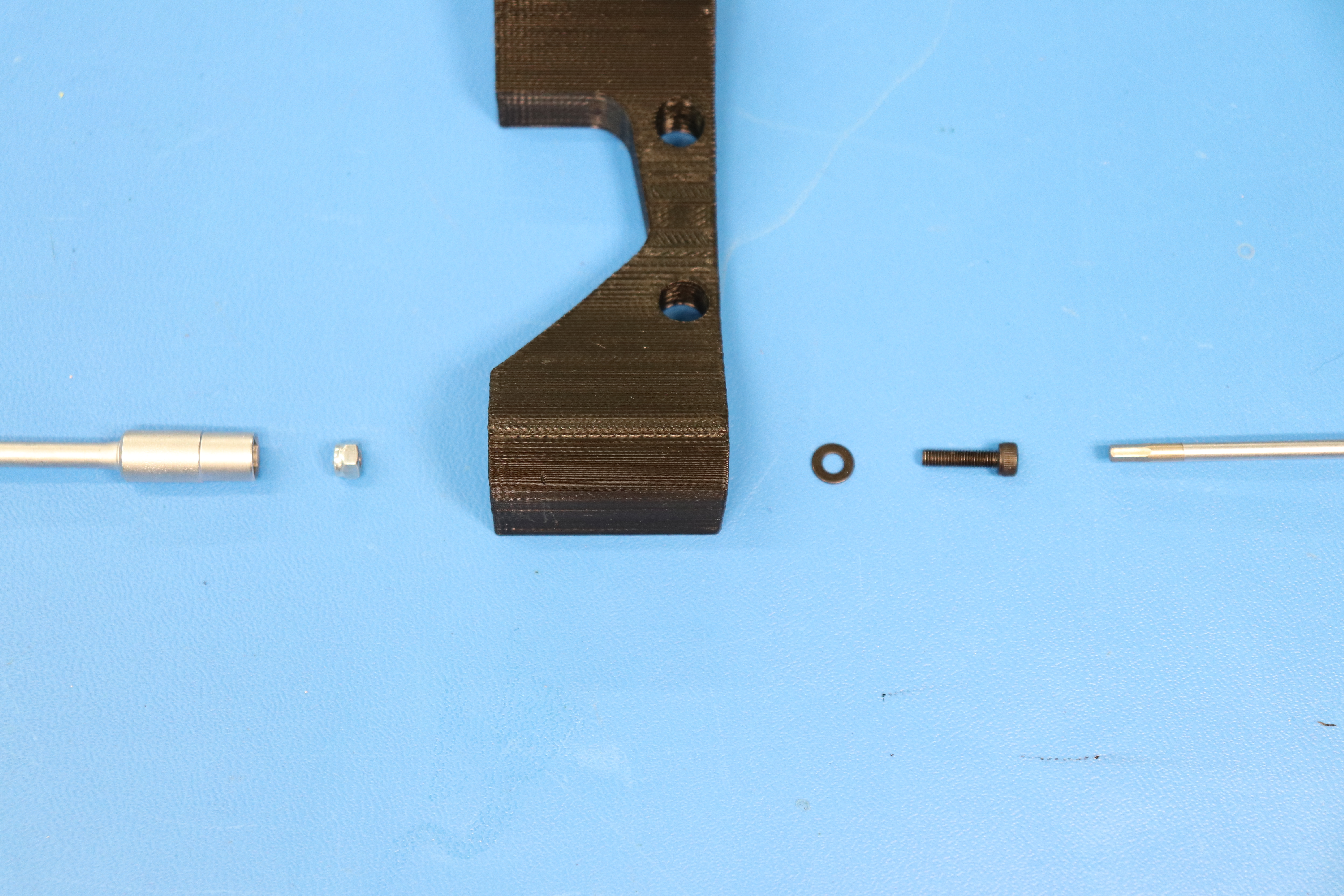
Put the M3 nyloc nut [HD-NT0001] into the 5.5 mm nut driver.
Insert the 5.5mm nut driver in to the Y-Rod Mount with the ".5" on the nut driver facing the top of the printed part, this ensures proper alignment of the nyloc nut. Make sure you press the driver to the bottom of the bore.
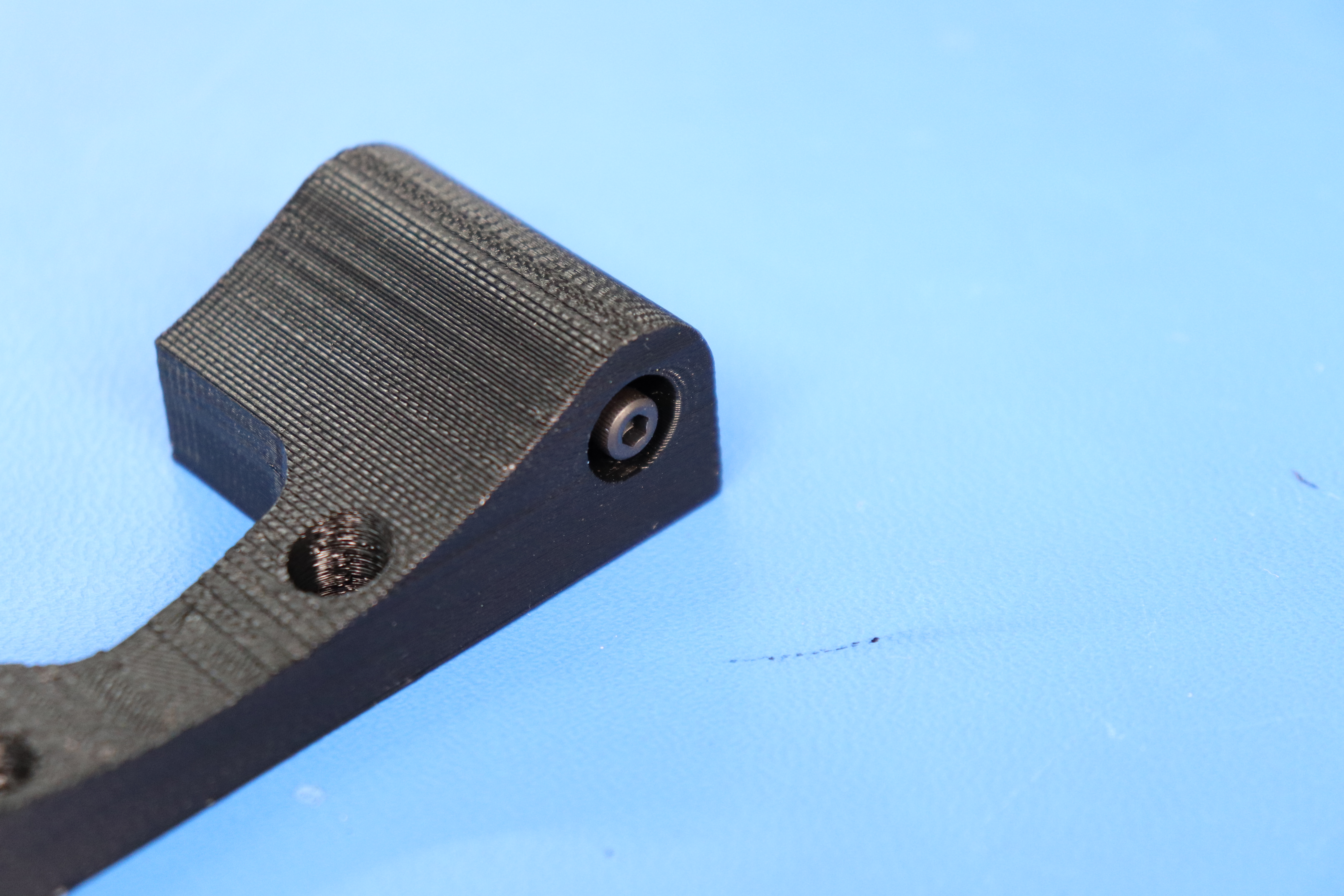
Then, use a M3 x 12 SHCS [HD-BT0039] and an M3 washer [HD-WA0038] to pull the nyloc into the hexagon shaped hole in the printed Y-Rod Mount [PP-IS0064] with a 2.5 mm hex driver or electric screwdriver.
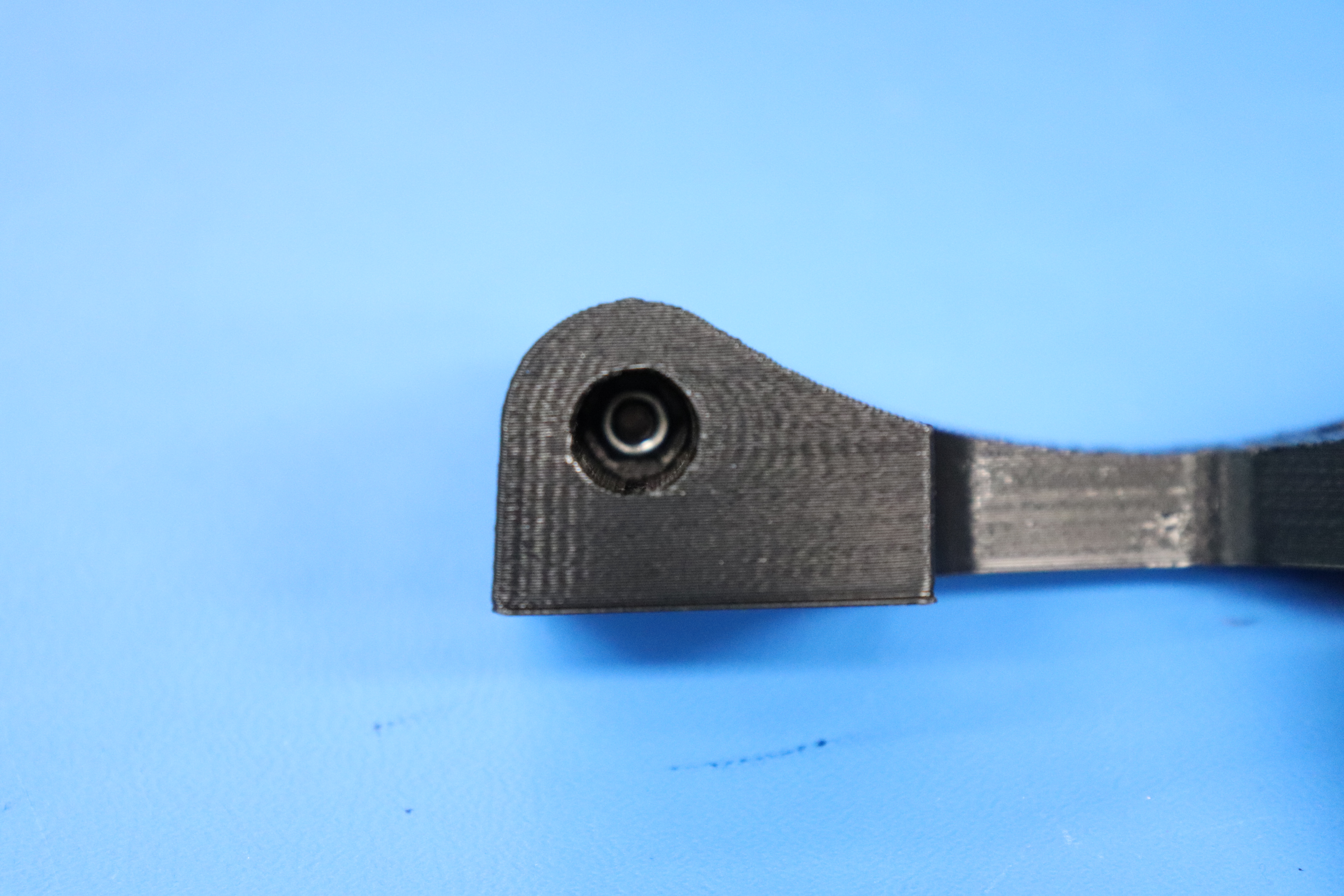
Inspect the nyloc nut to make sure it is seated into the nut trap correctly.
Back the screw out until it is flush with the printed part.
Repeat this process for the other side of the printed part.


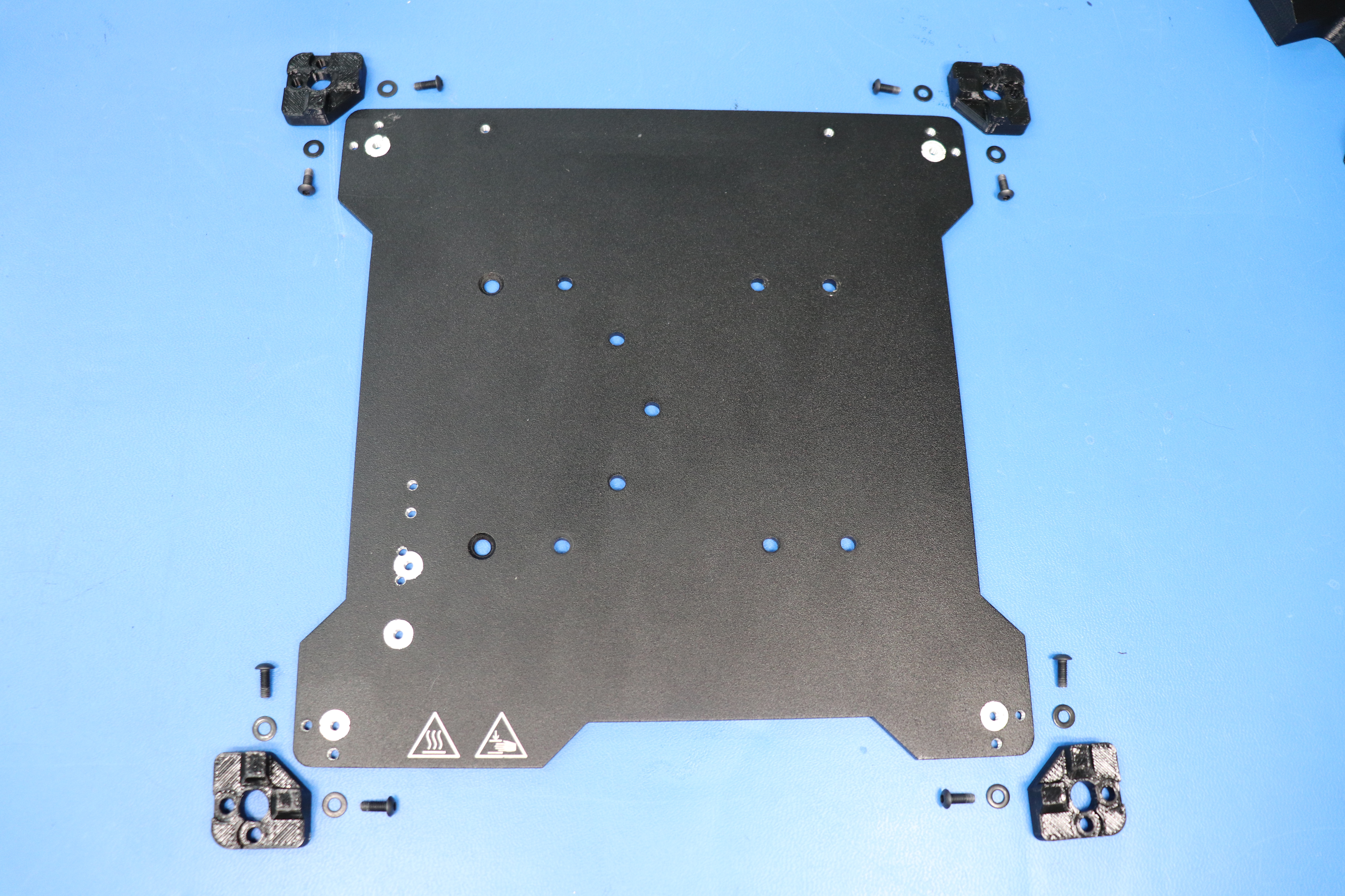
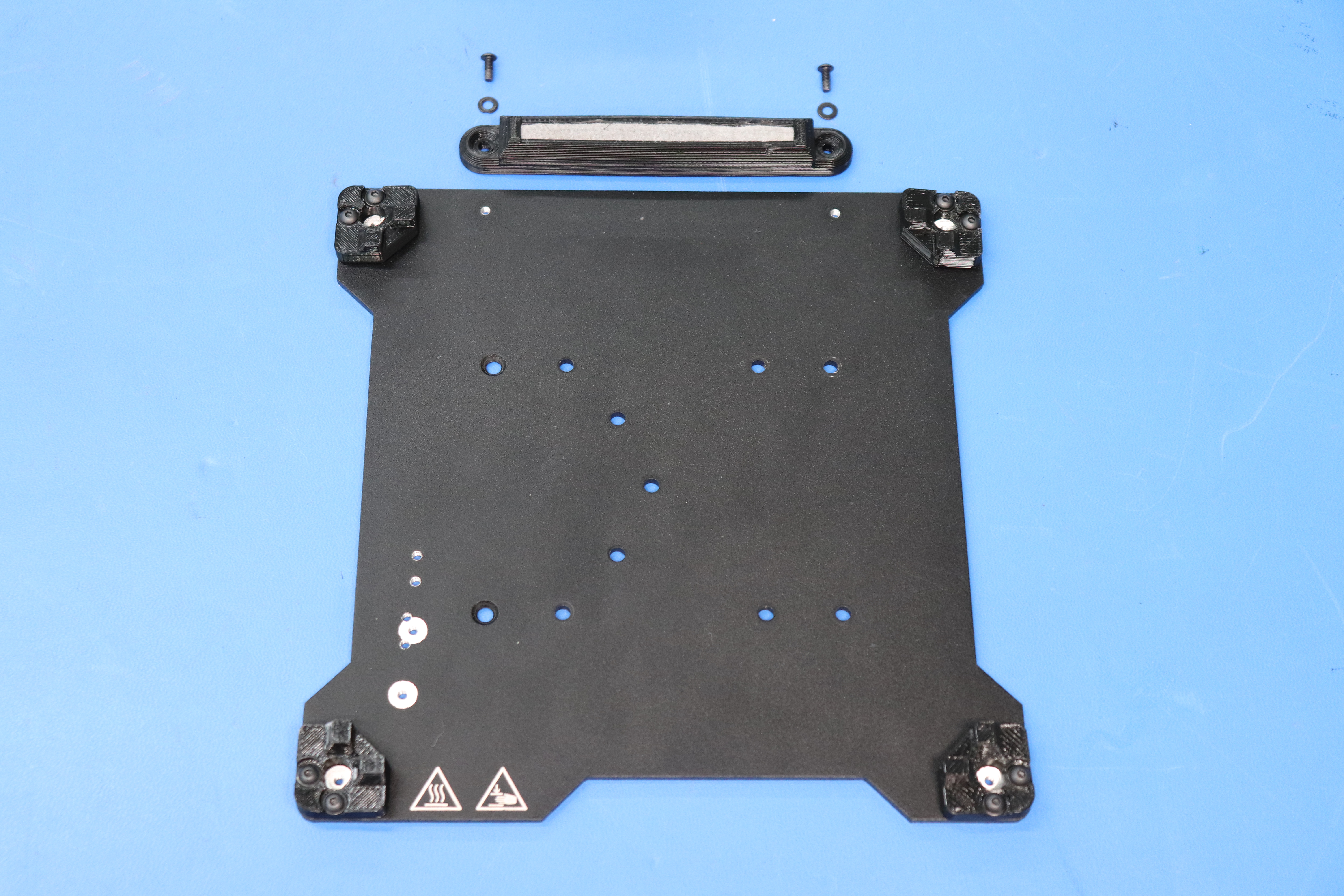
Using M3 x 10 BHCS [HD-BT0148] and M3 washers [HD-WA0038] fasten the urethane bed corners [PP-GP0296] to the bed plate [PP-FP0138] with a 2 mm hex driver. These may be left loose for the time being; they will be tightened in position with the bed heater at Calibration.
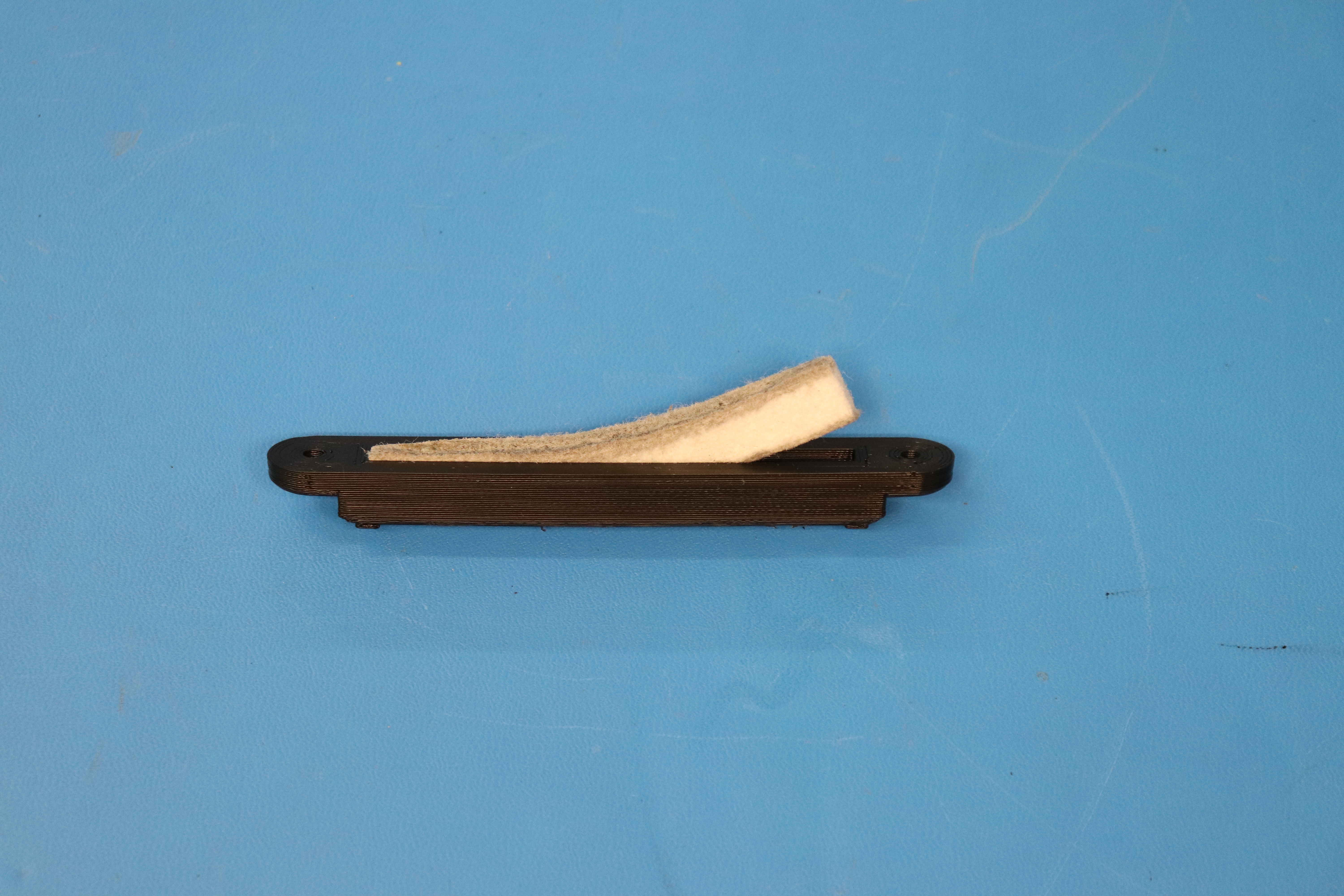
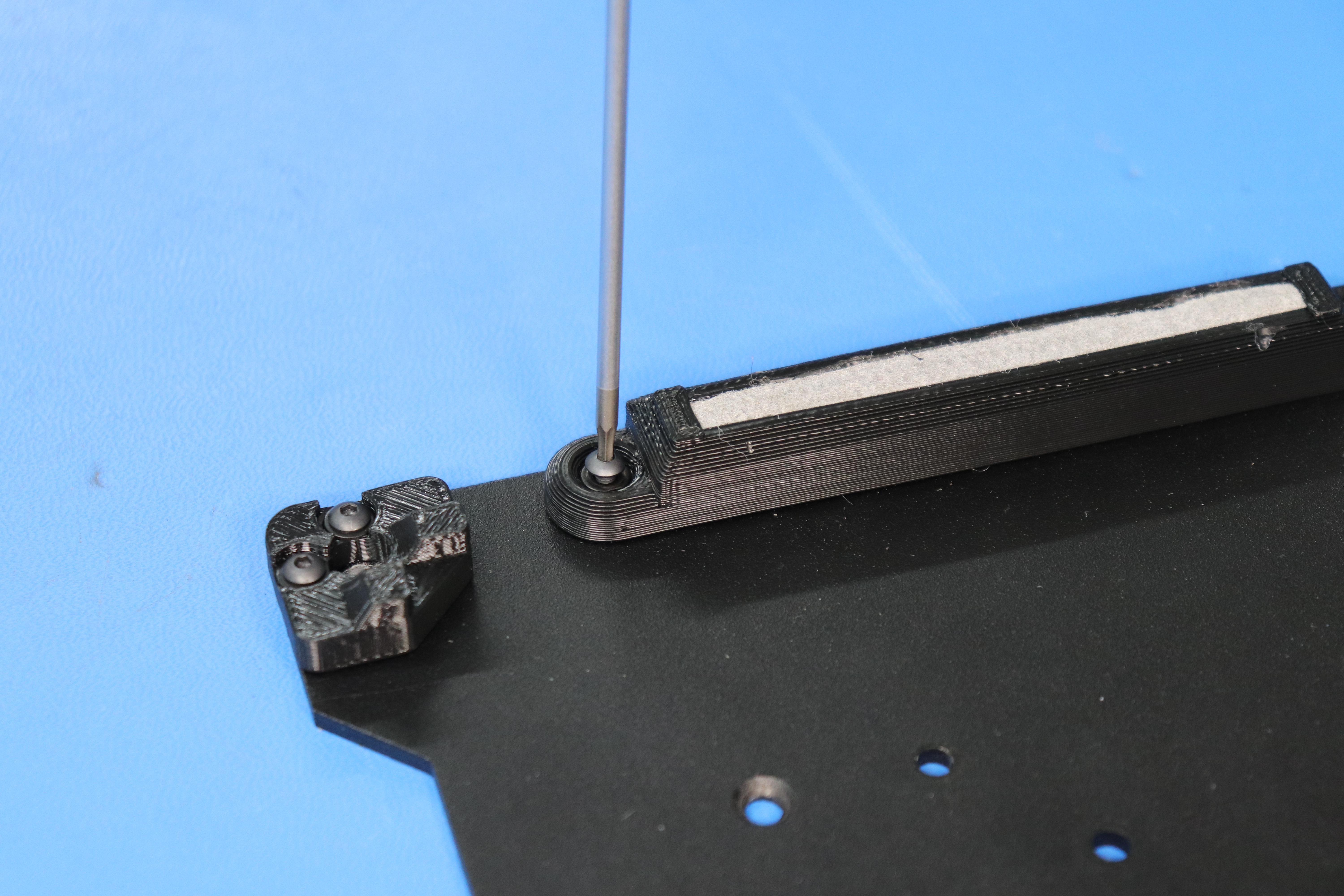
Push the felt wiper pad [AS-PR0023] into the wiper pad mount [PP-GP0231]. Then, attach the wiper pad mount to the bed plate using two M3 x 8 BHCS [HD-BT0137] and two M3 washers [HD-WA0038]. Leave the wiper pad fasteners loose by a little bit so that they do not interfere with the bed installation in calibration.
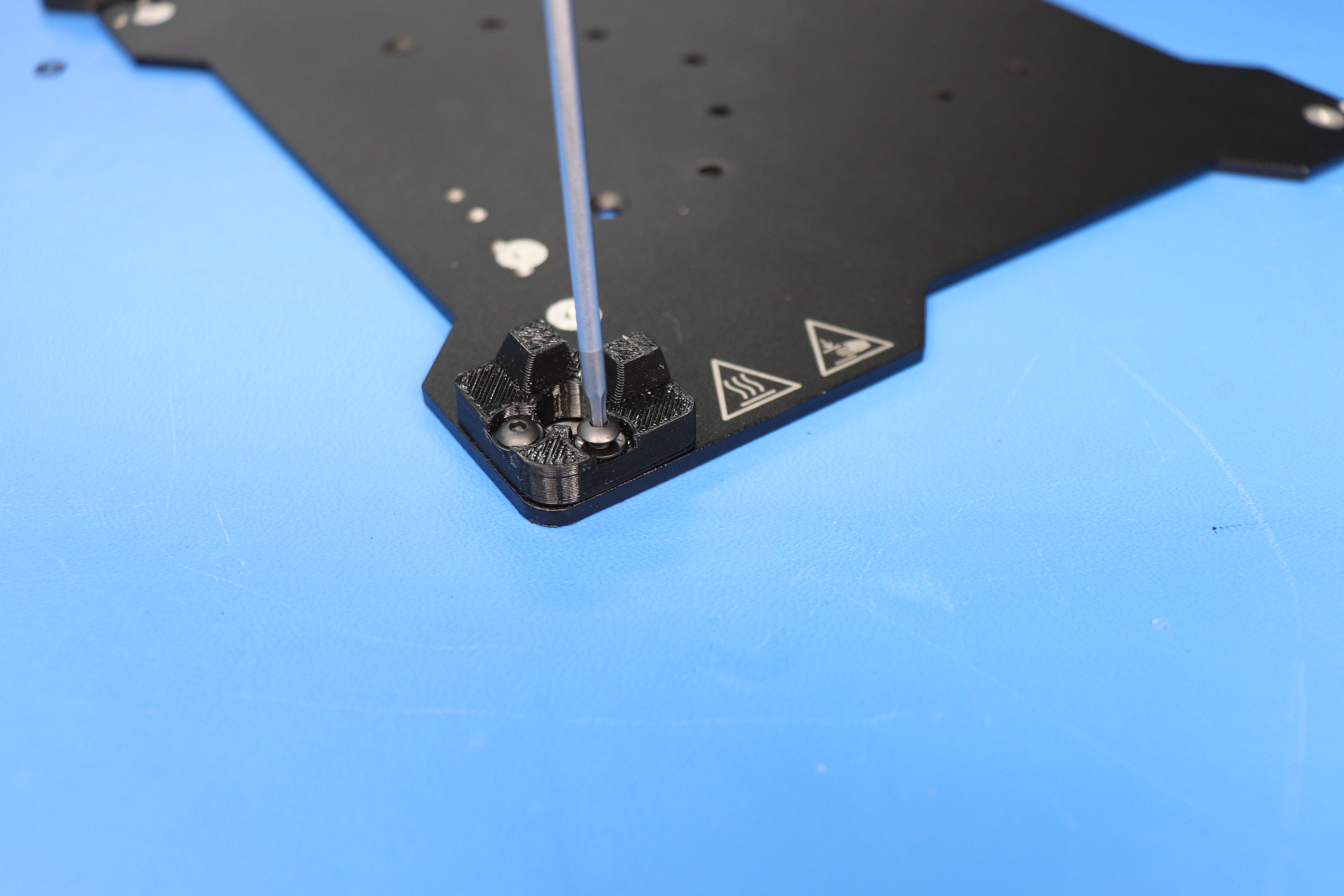
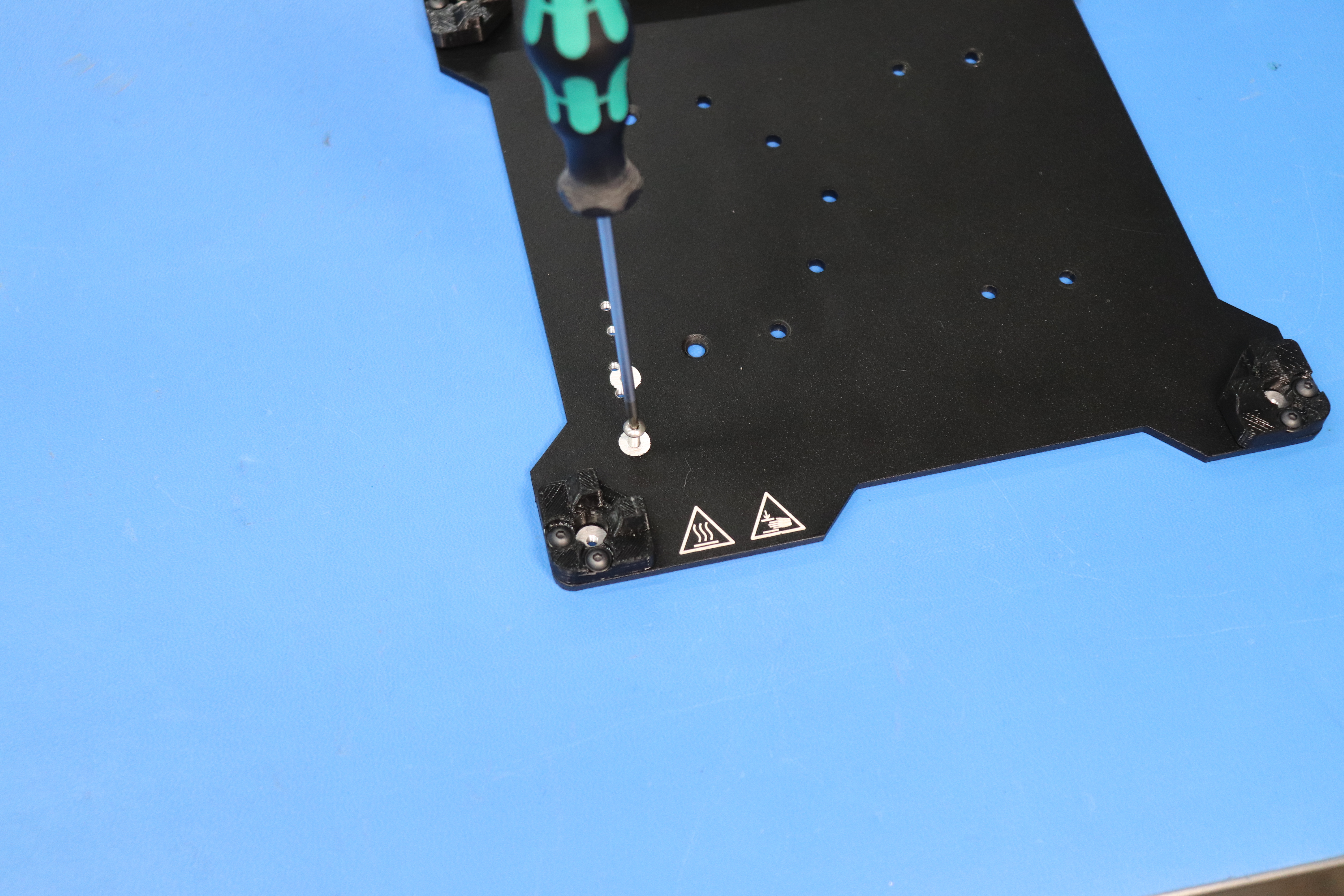
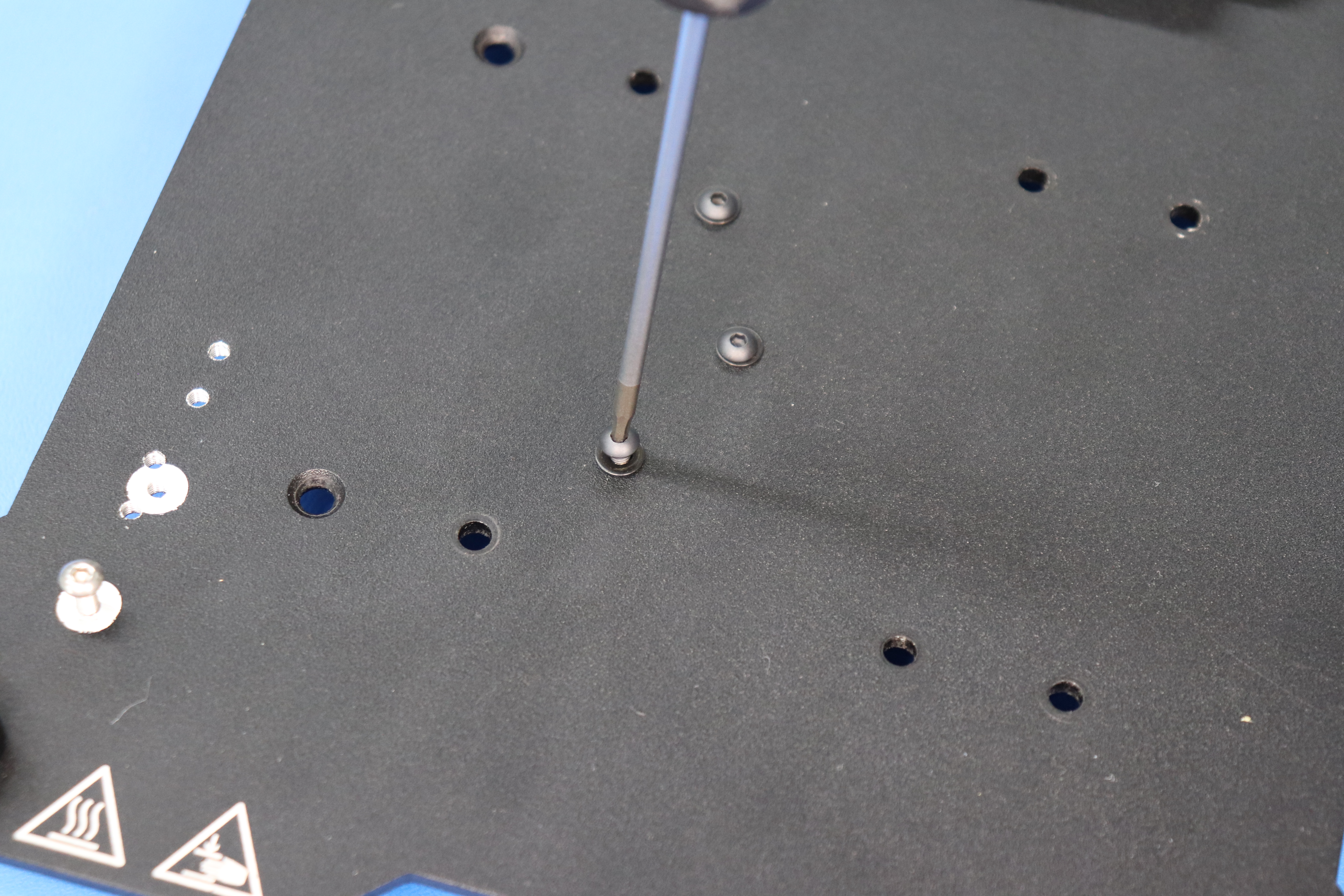
Install the M3 x 8 stainless steel BHCS [HD-BT0104] into the threaded hole towards the bottom left of the bed plate as pictured.
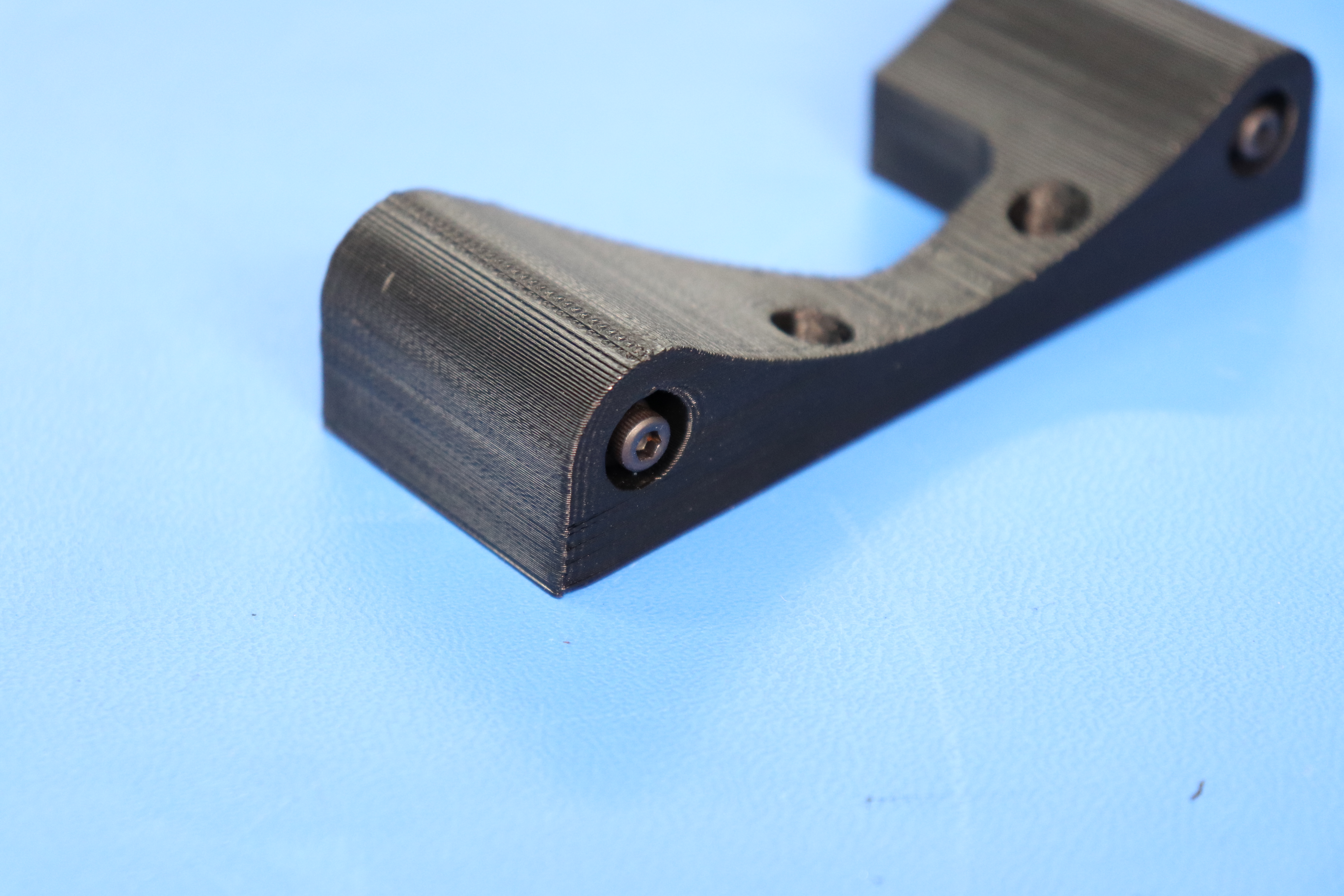
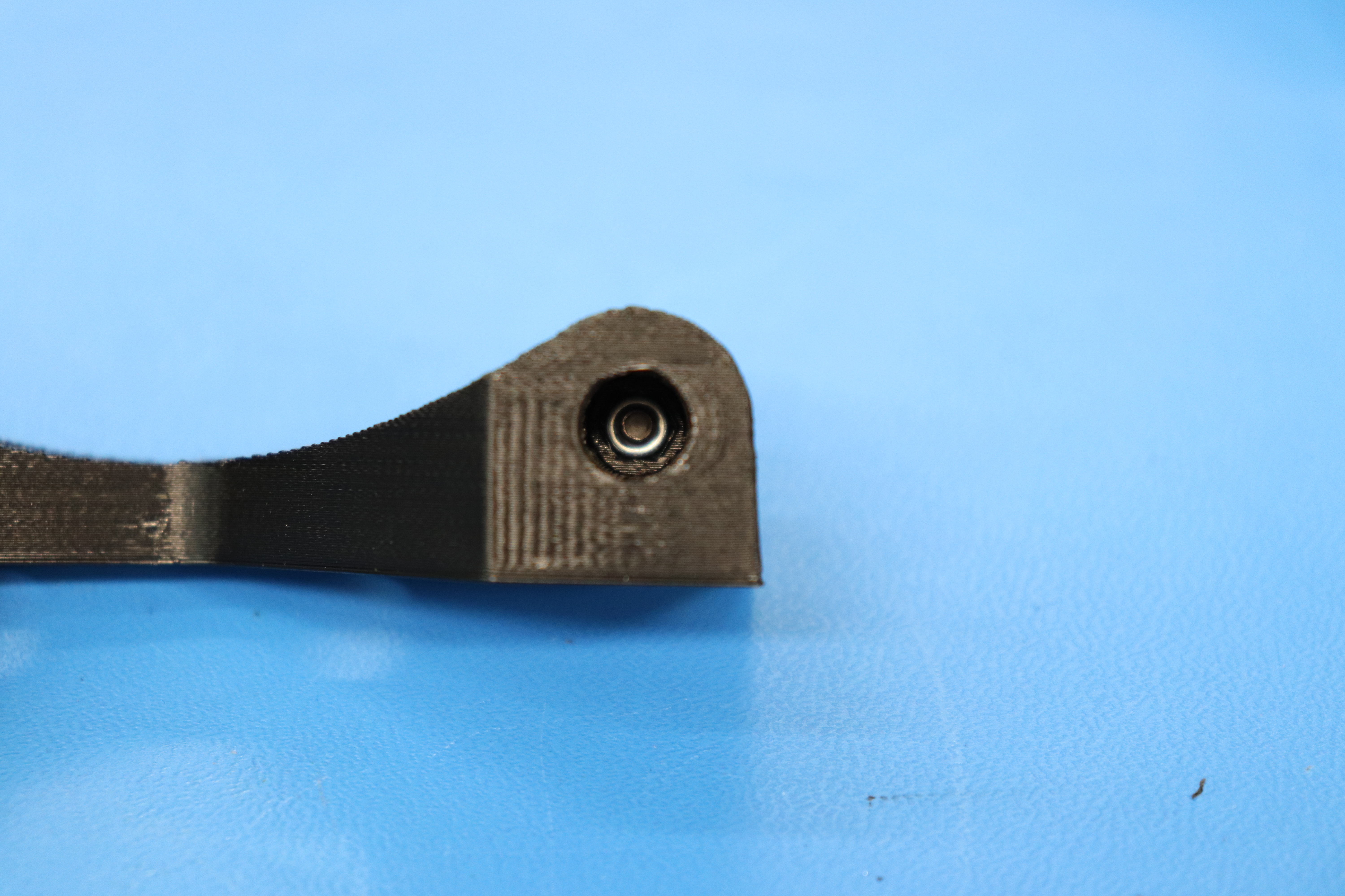
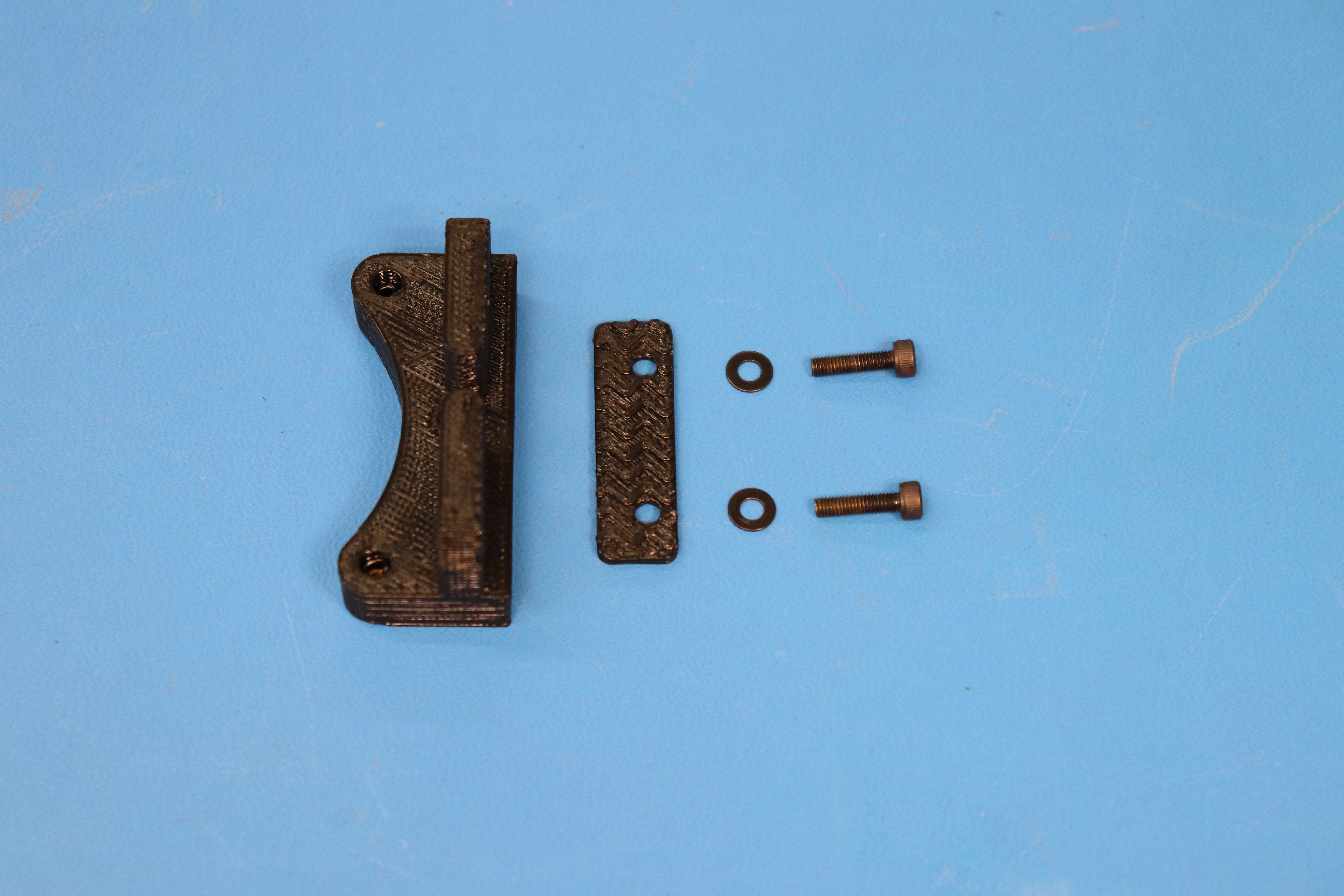
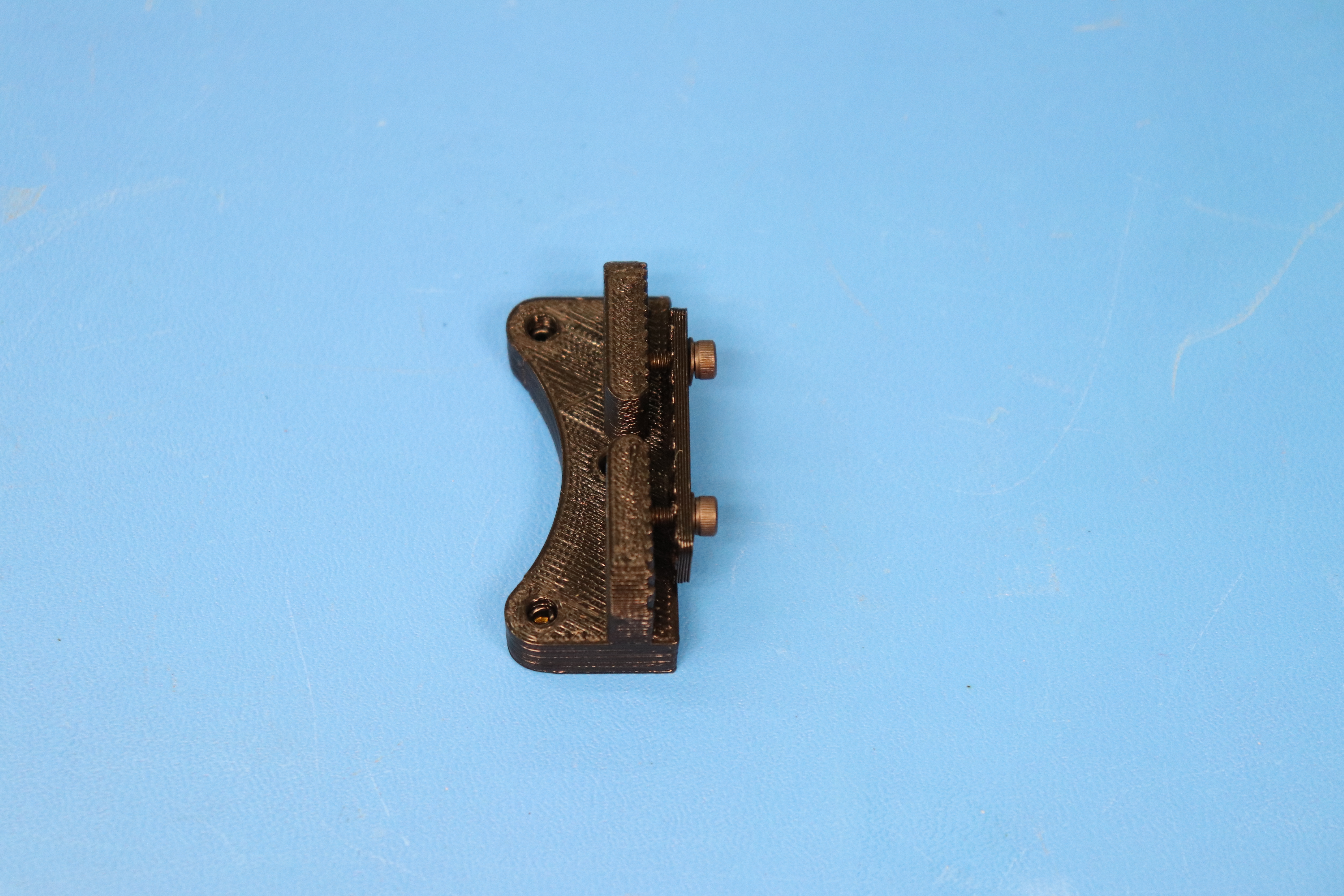
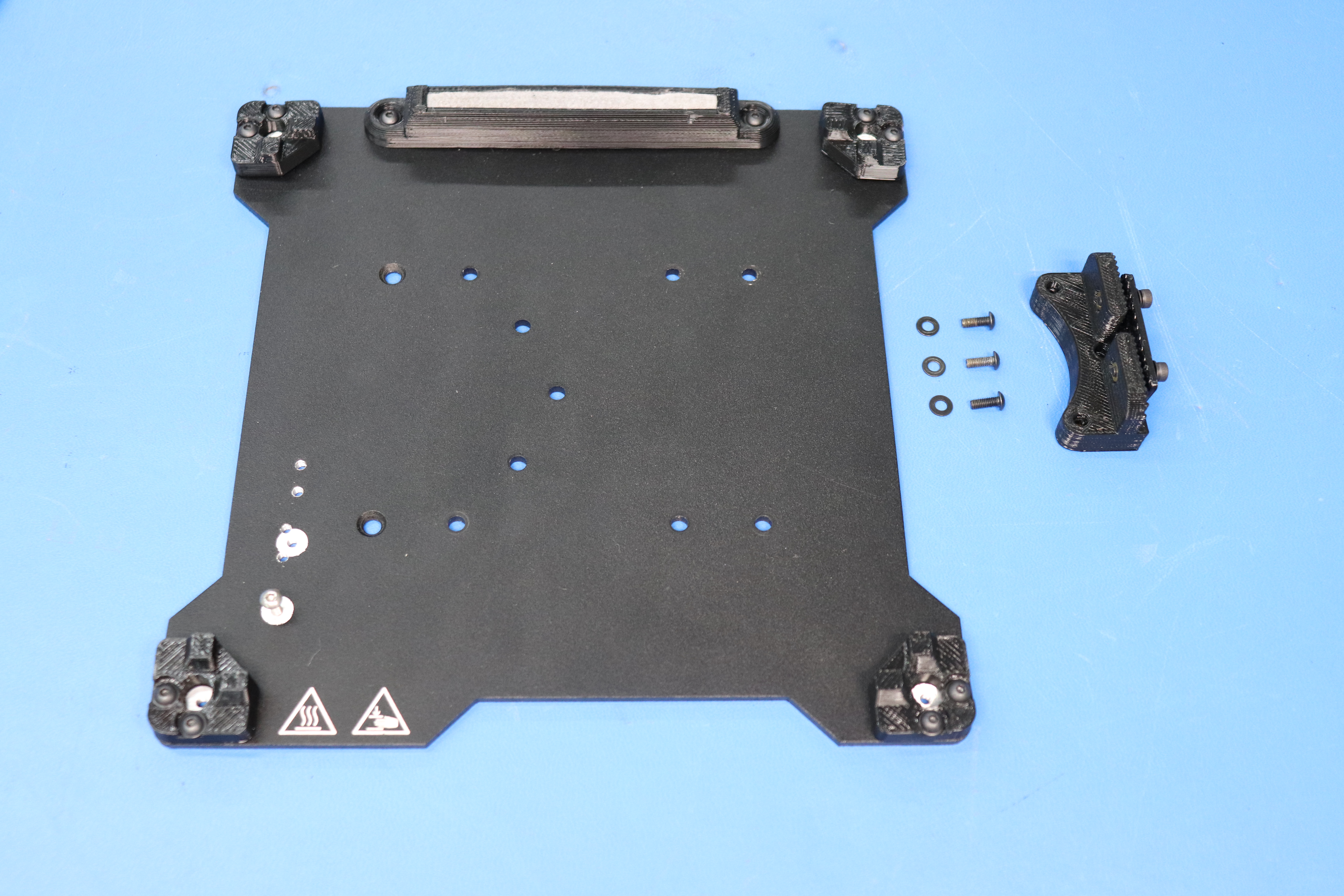
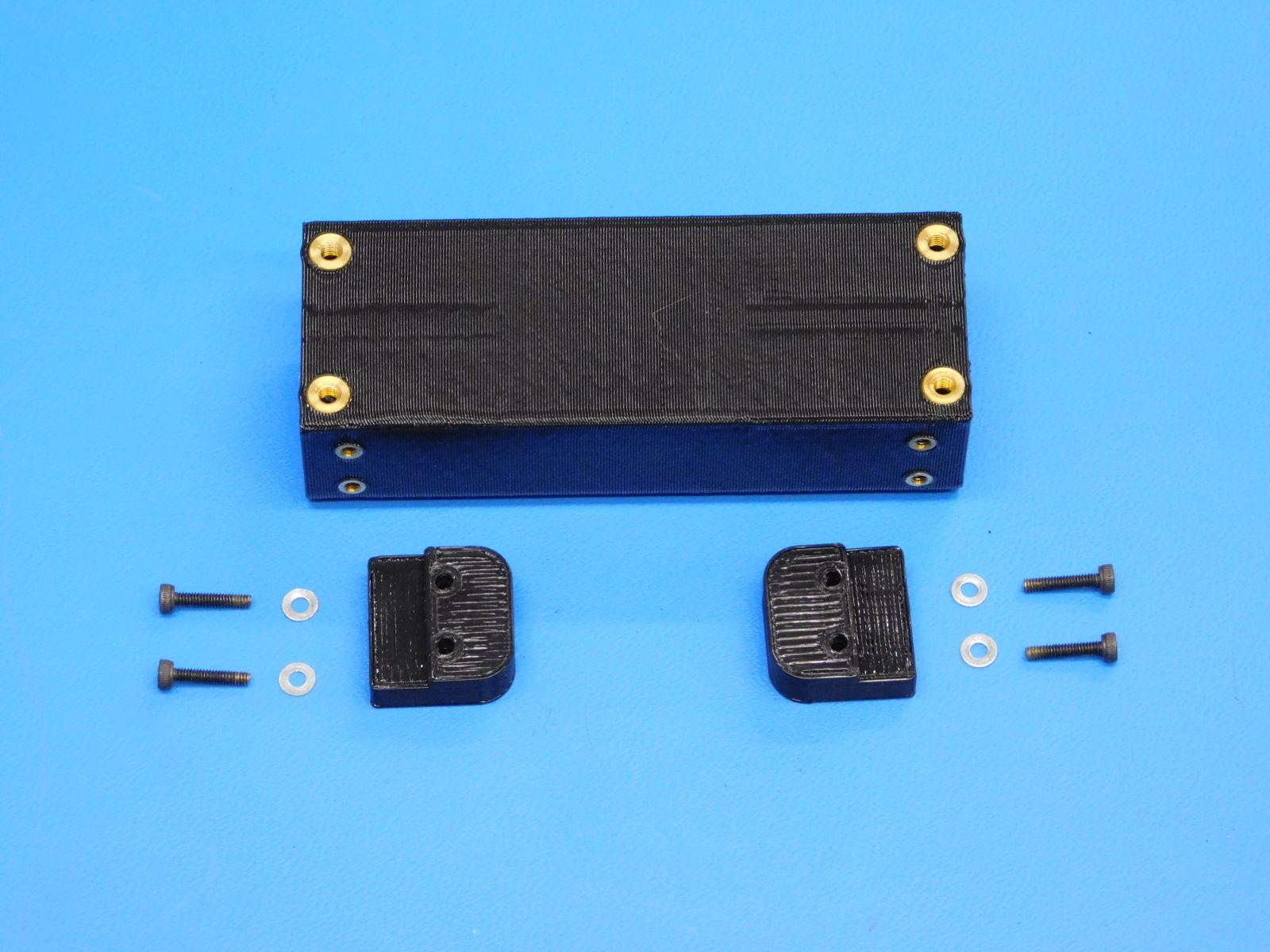
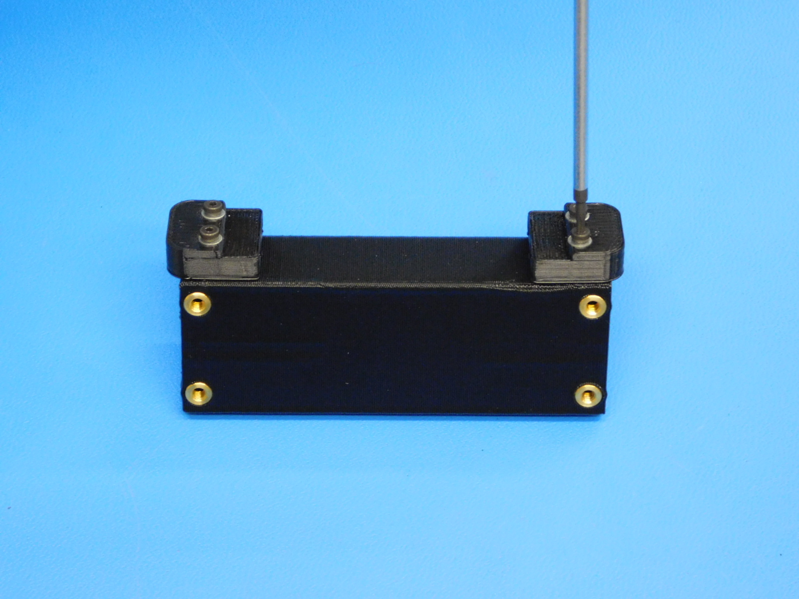
Attach the belt clamp [PP-GP0277] to the belt clamp assembly [AS-PR0060] using two M3 x 12 SHCS [HD-BT0039] and two M3 washers [HD-WA0038] with the wider side towards the base of the mount. Then, attach the assembly to the bed plate using three M3 x 8 BHCS [HD-BT0137] and three more M3 washers.
Using M2 x 10 SHCS [HD-BT0107] and M2 washers [HD-WA0012] fasten the urethane bumpers [PP-GP0332] to the single bearing assembly [PP-IS0073] with a 1.5 mm hex driver.
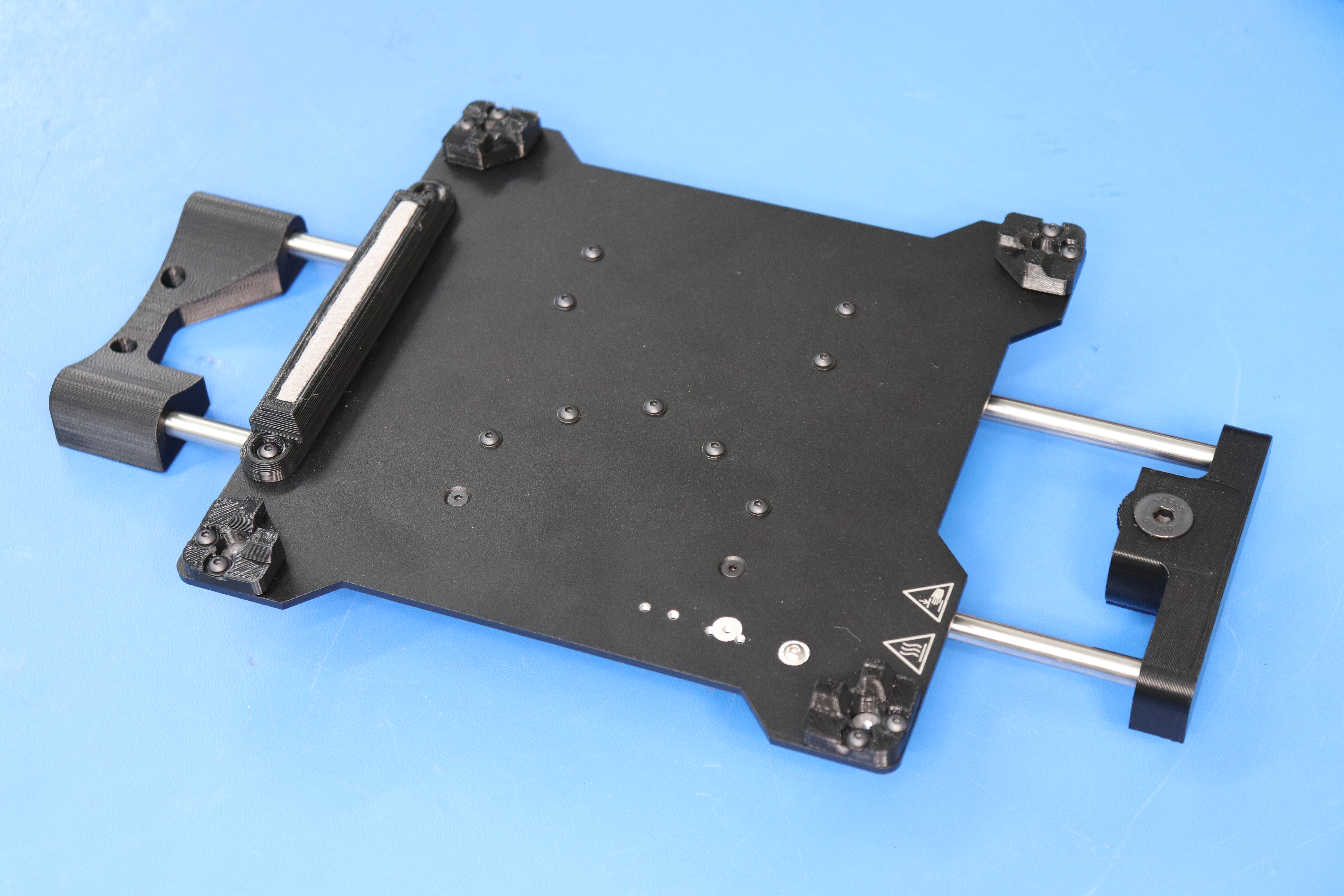
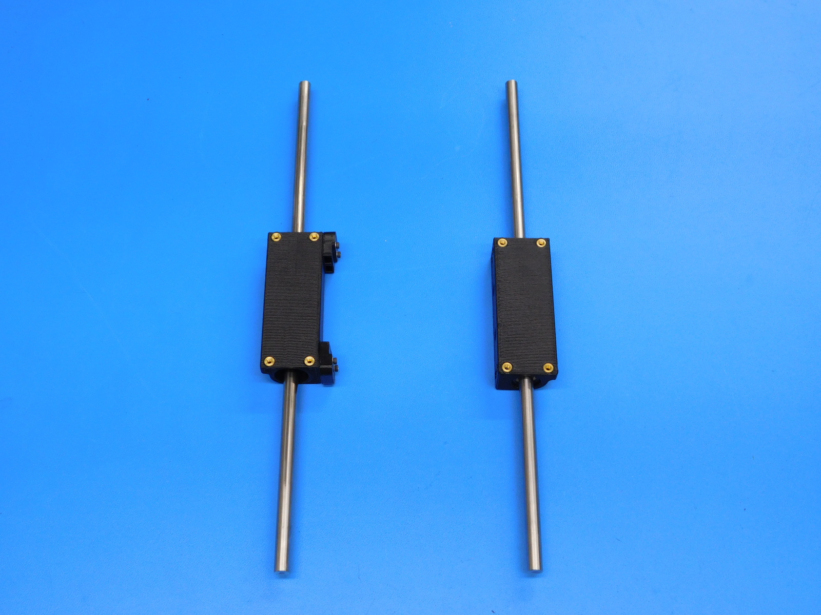
Slide the bushing assemblies [PP-IS0073] and [PP-IS0066] onto the 8 mm smooth rods [HD-RD0035].
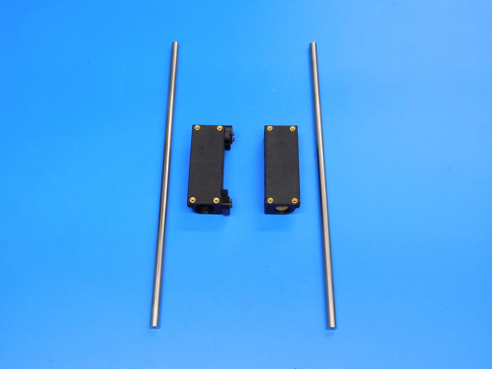
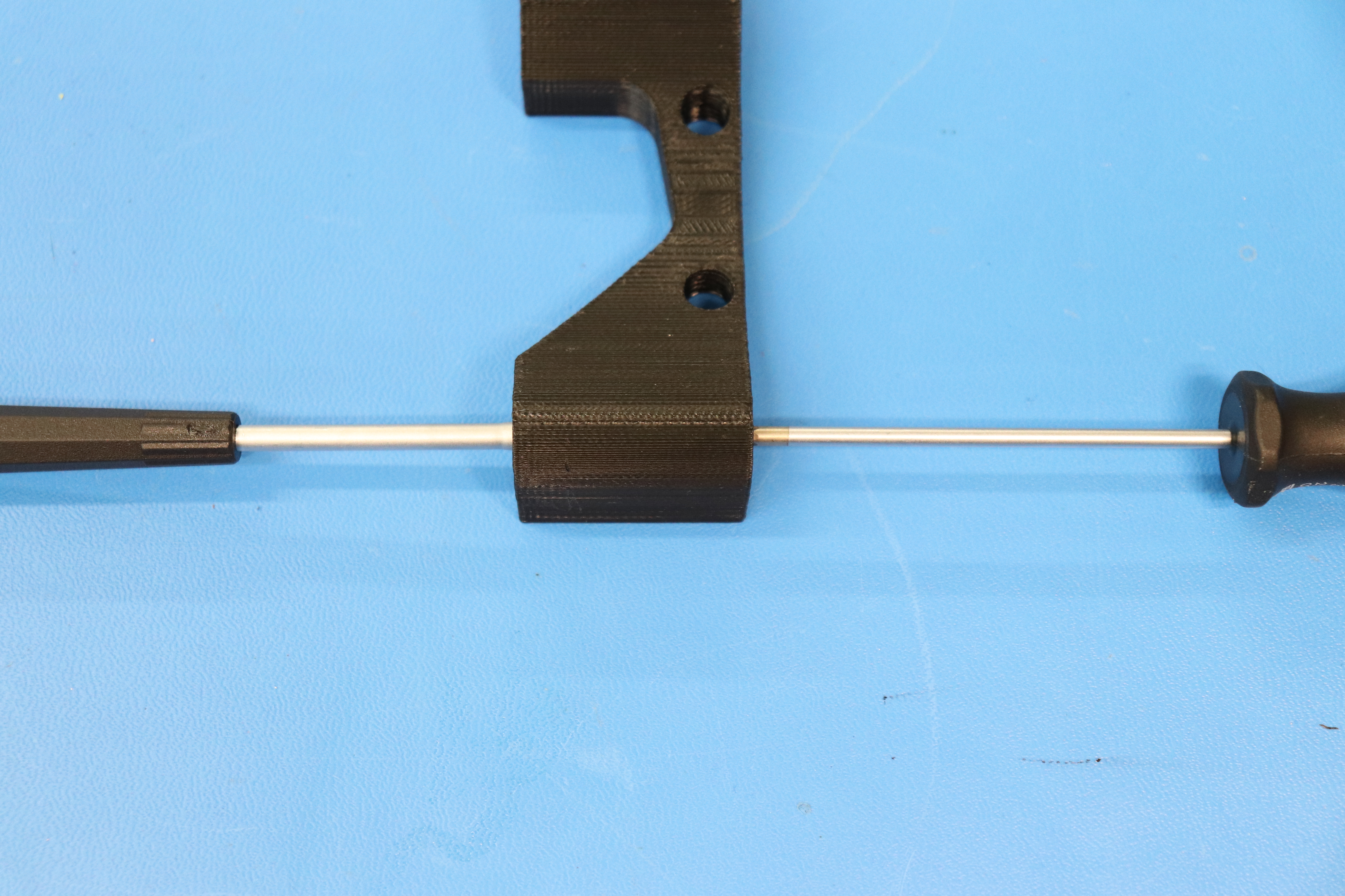
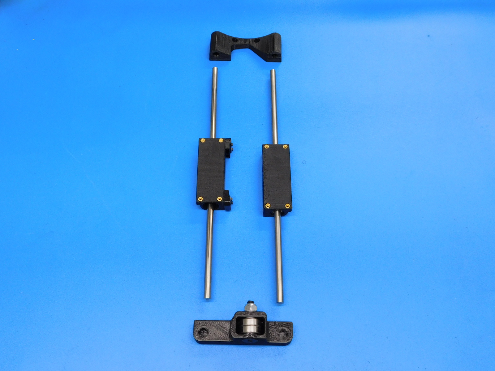
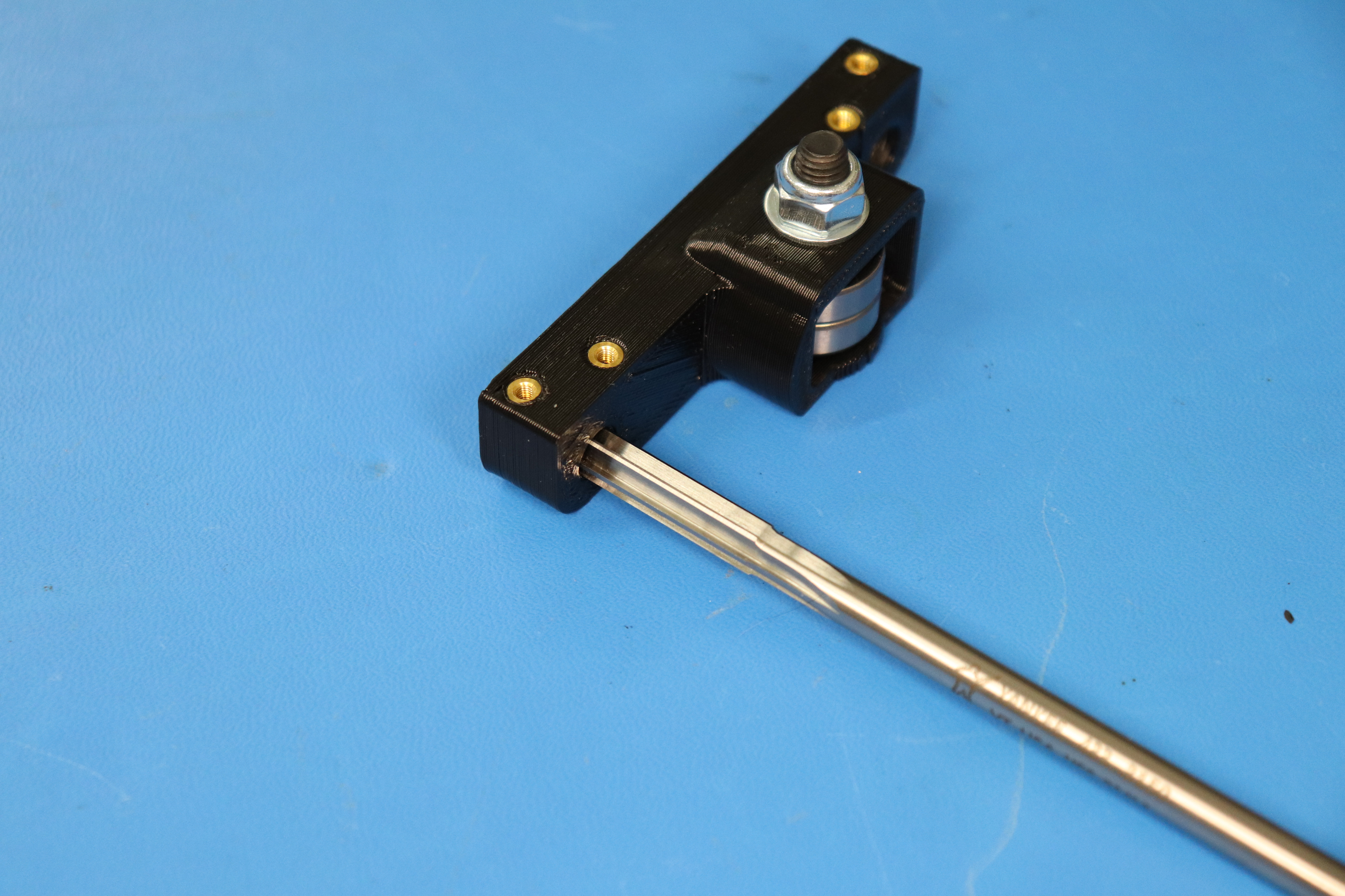
Use the 8 mm reamer tool [TL-PW0225] to gently ream the y idler assembly [AS-PR0068]. Take care to keep the tool straight and to not remove too much material which would result in a loose fitting rod. Take note of the orientation of the bearing holders shown in the picture, then slide the smooth rods into the y idler assembly until they are fully seated. If they do not seat, it might be a sign that the reamer tool needs to be used to clean up the diameter of the blind hole in the printed part. Slide the other end of the rods into the motor side mount [PP-IS0064].
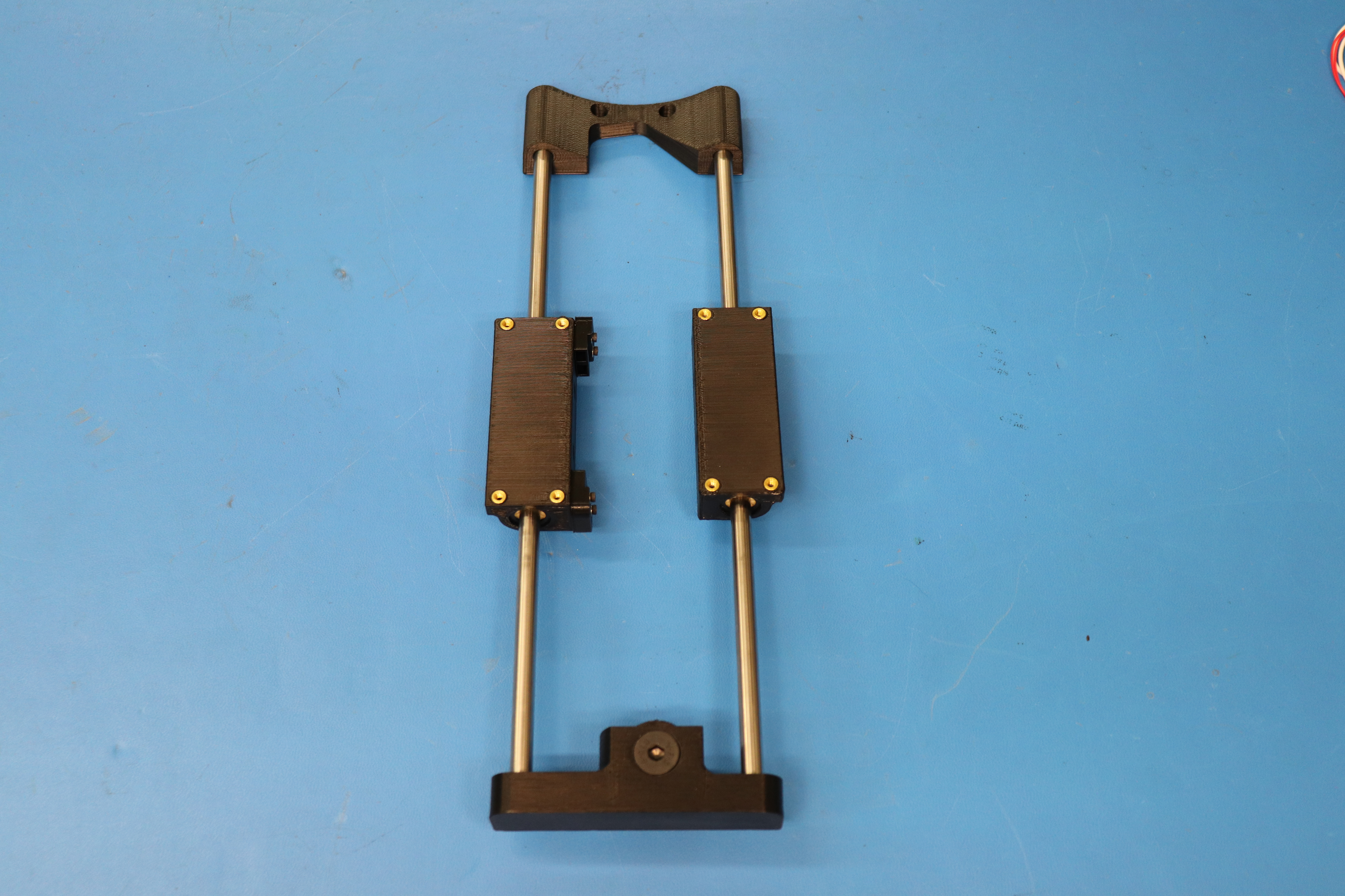
Using six M3 x 8 mm BHCS [HD-BT0137] and M3 washers [HD-WA0038] and two M3 x 6 mm FHCS [HD-BT0128] attach the bed plate assembly to the bearing holders.
These screws should be left loose for now, they will be tightened during Y-Axis Assembly to ensure proper alignment once the Bed Plate Assembly has been mounted to the Frame.
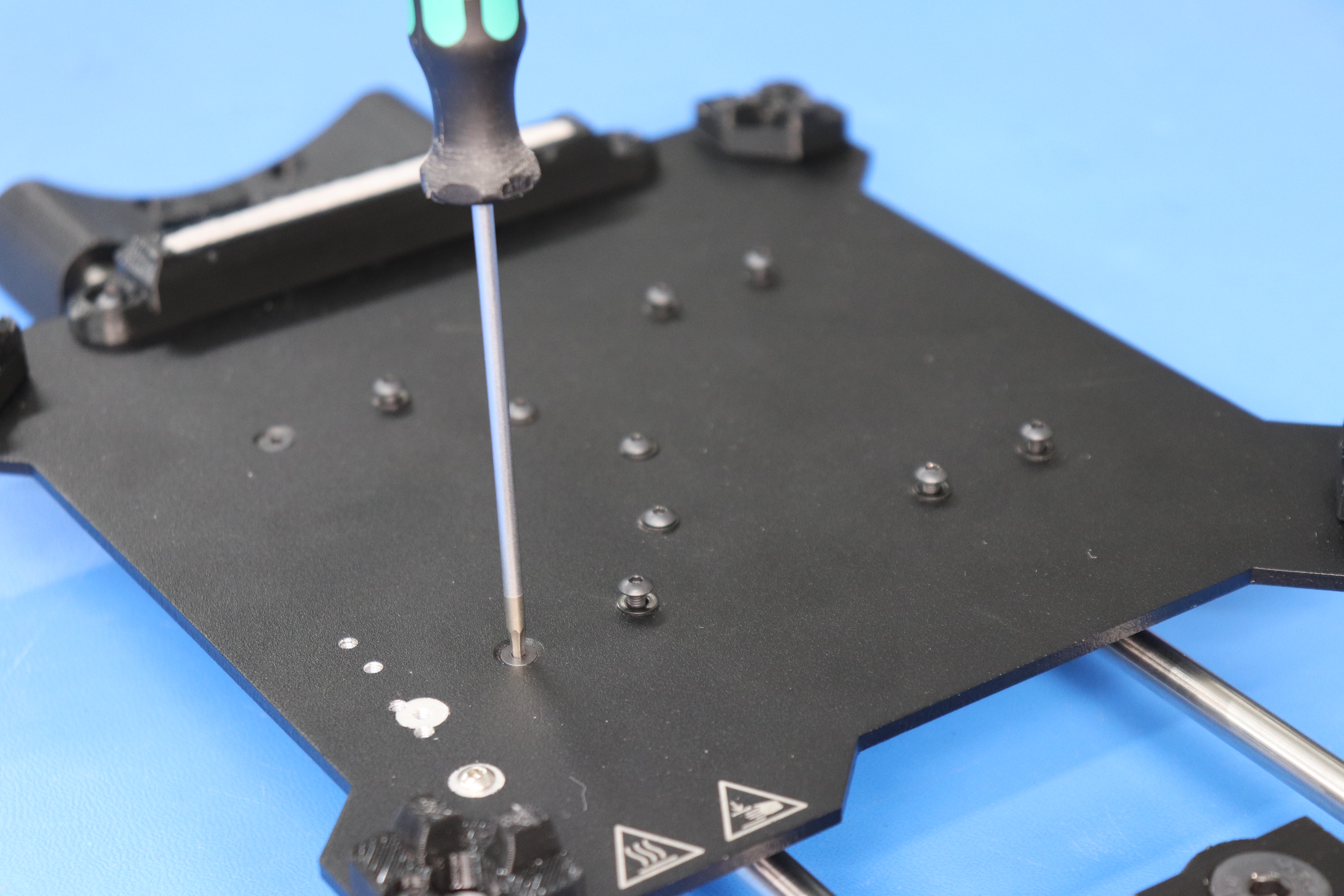
Make sure what you have looks like the picture.