Open HardwareAssembly Instructions
Guides for installation and assembly of the LulzBot line of products made by Aleph Objects, Inc.
Guides for installation and assembly of the LulzBot line of products made by Aleph Objects, Inc.
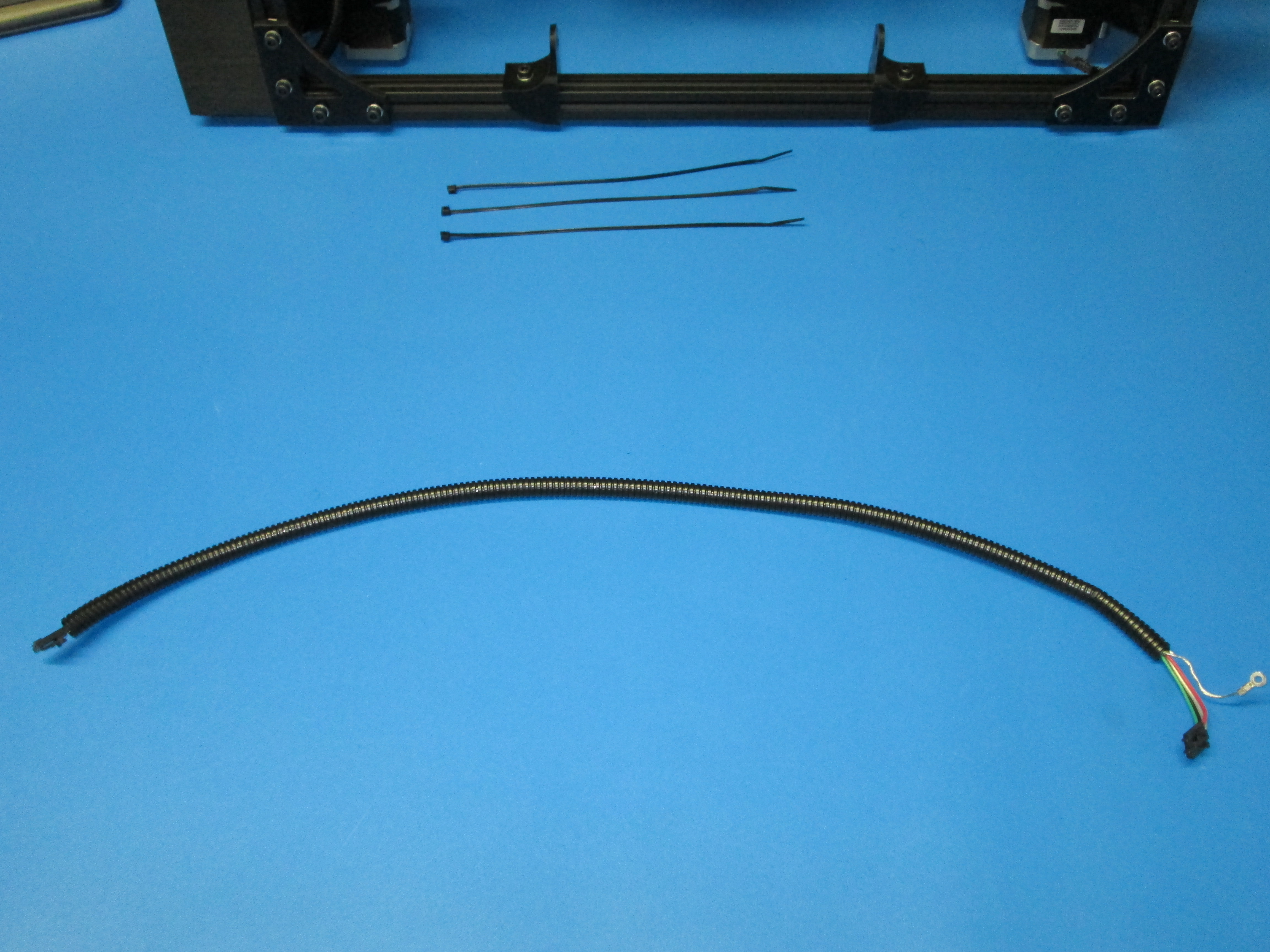
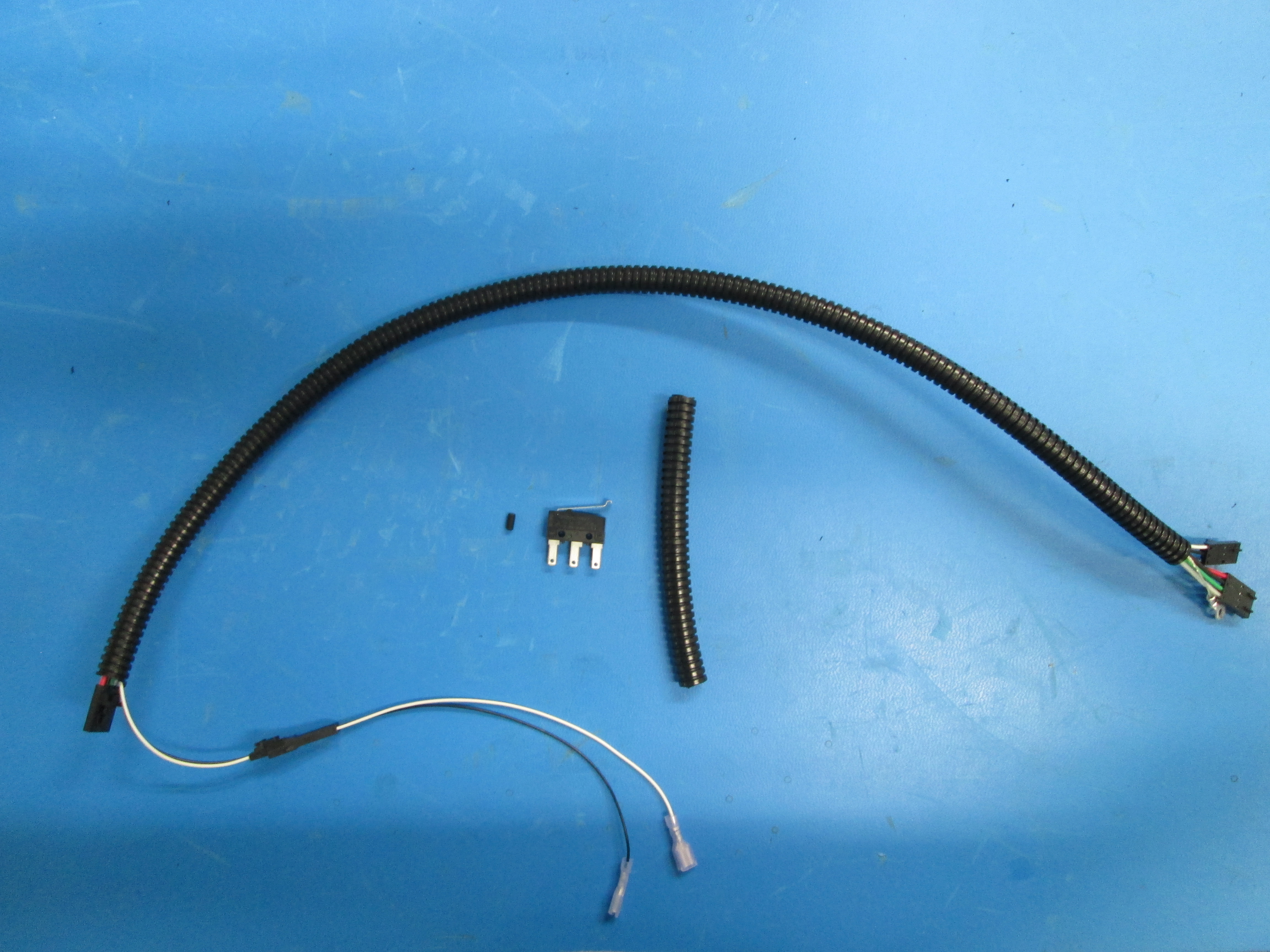
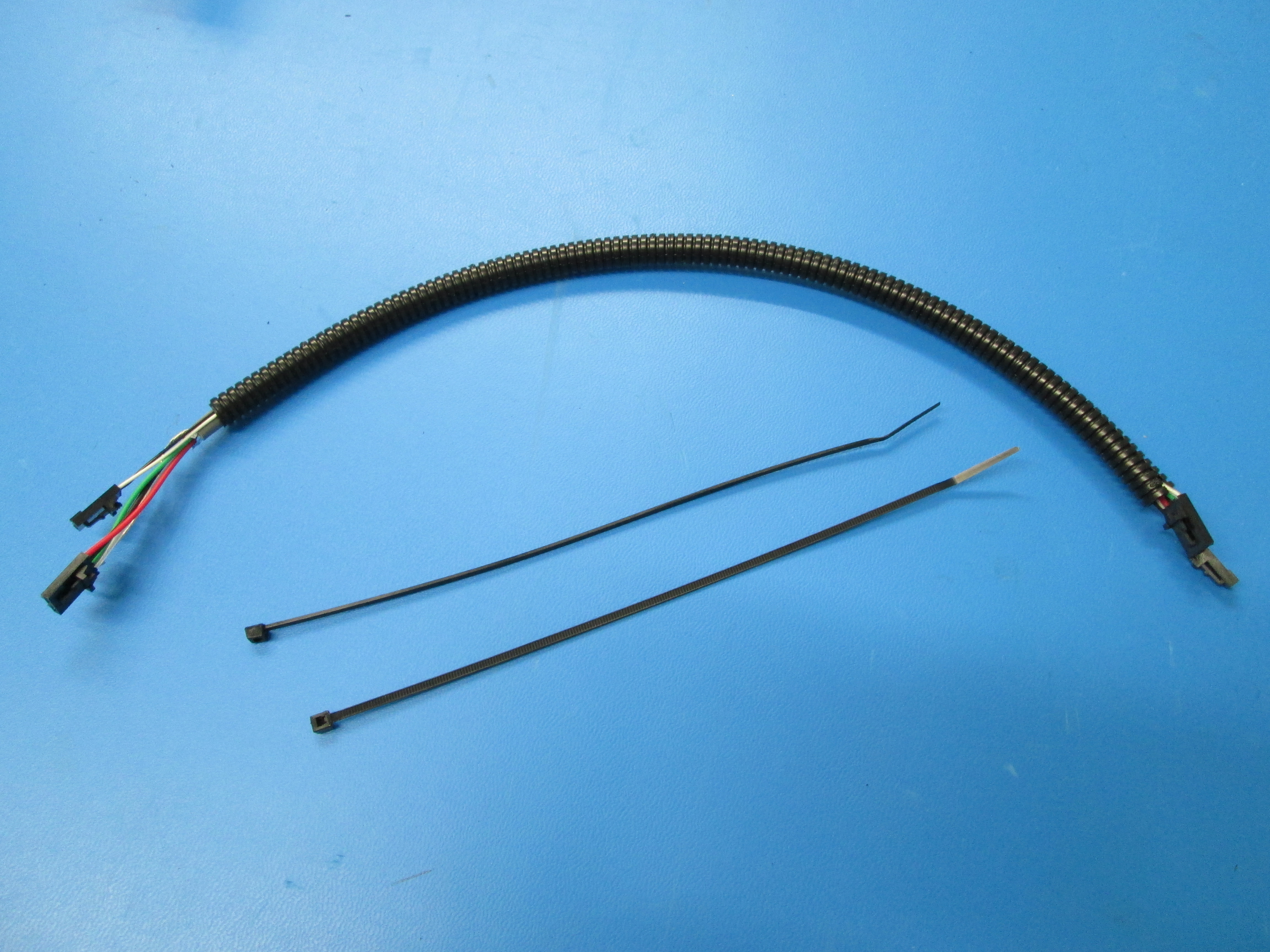
Components:
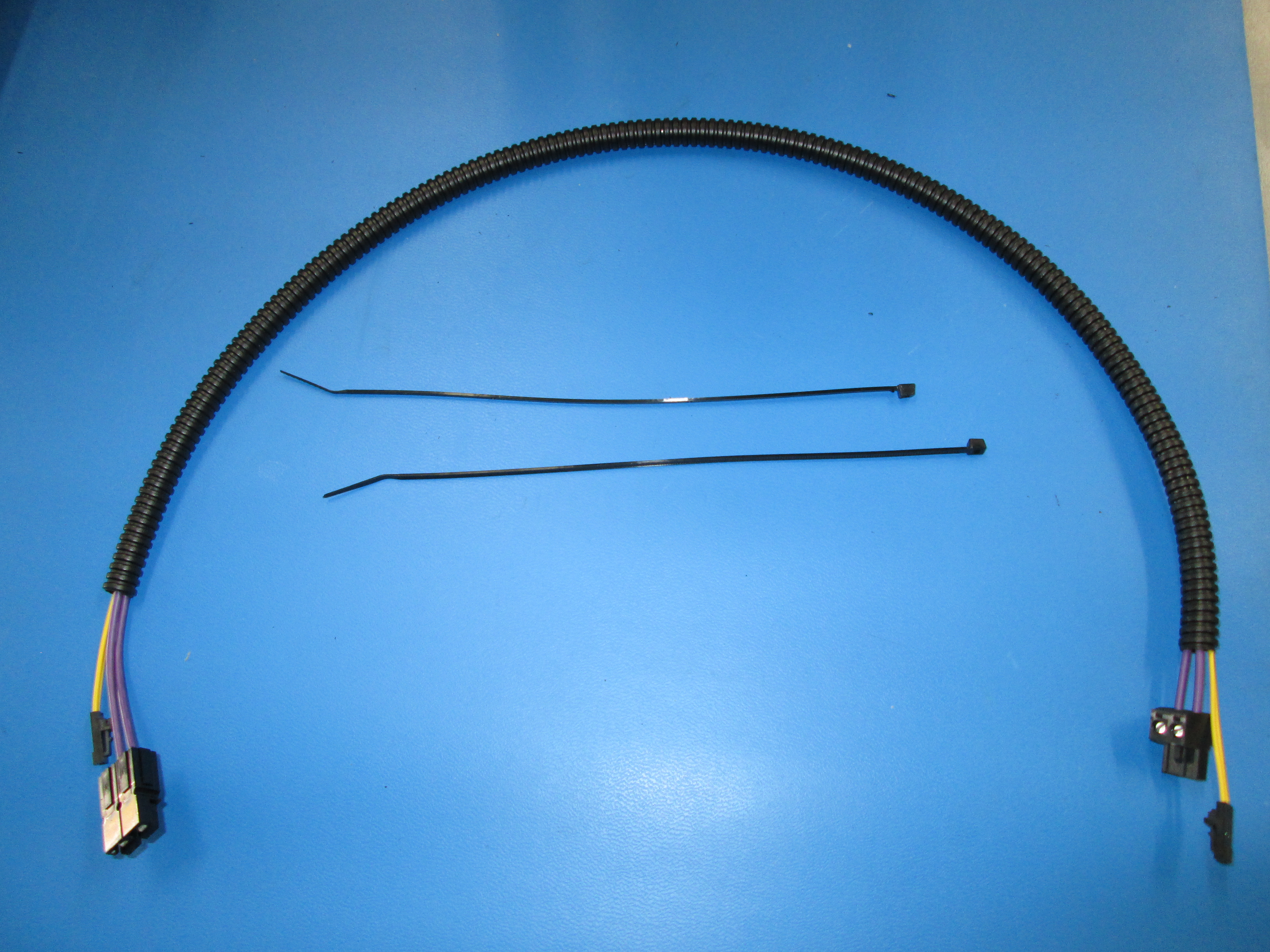
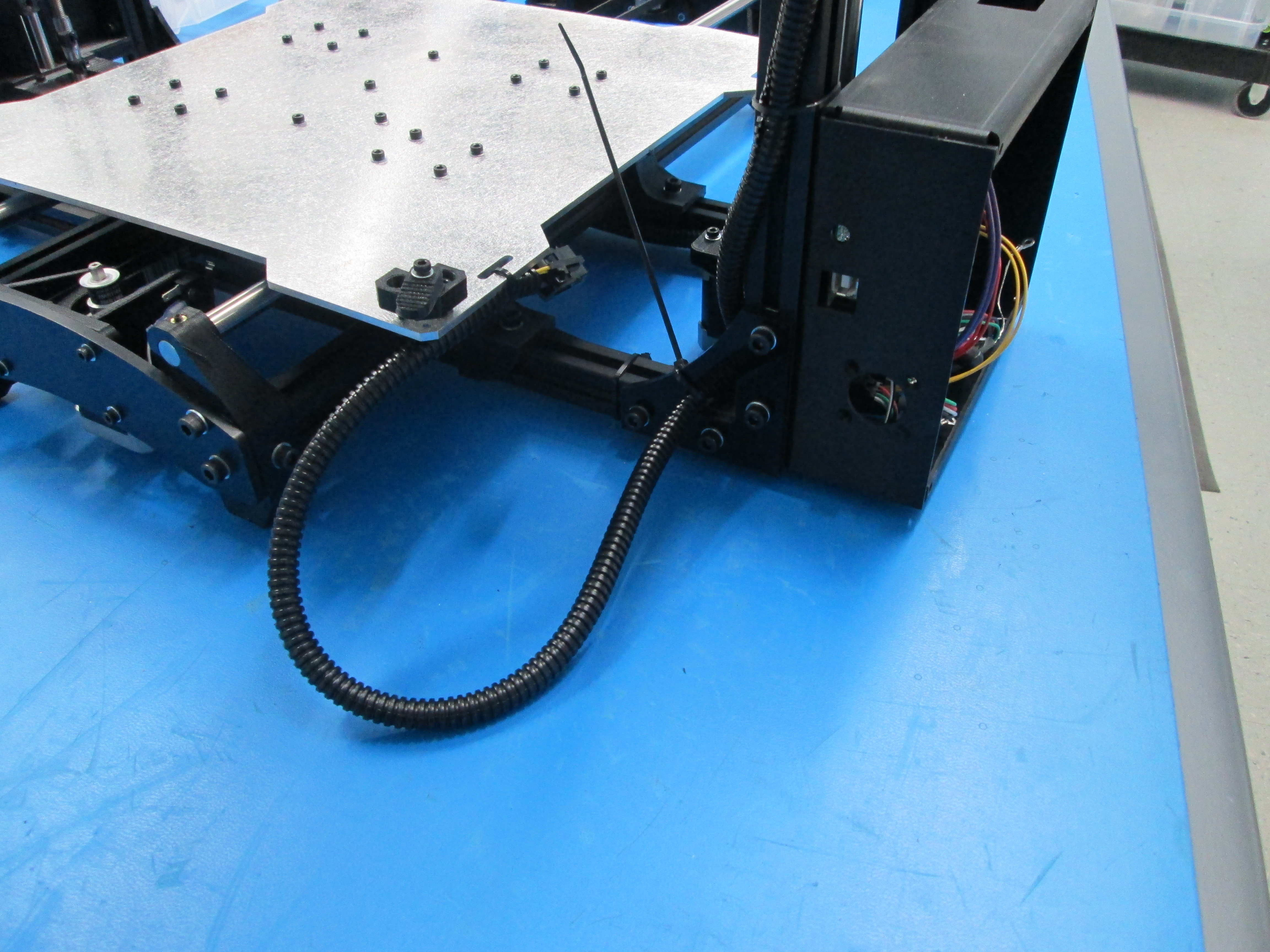
Corrugated tubing 100mm
Rubber feet
Thumb screws
Heat Bed
Tools:
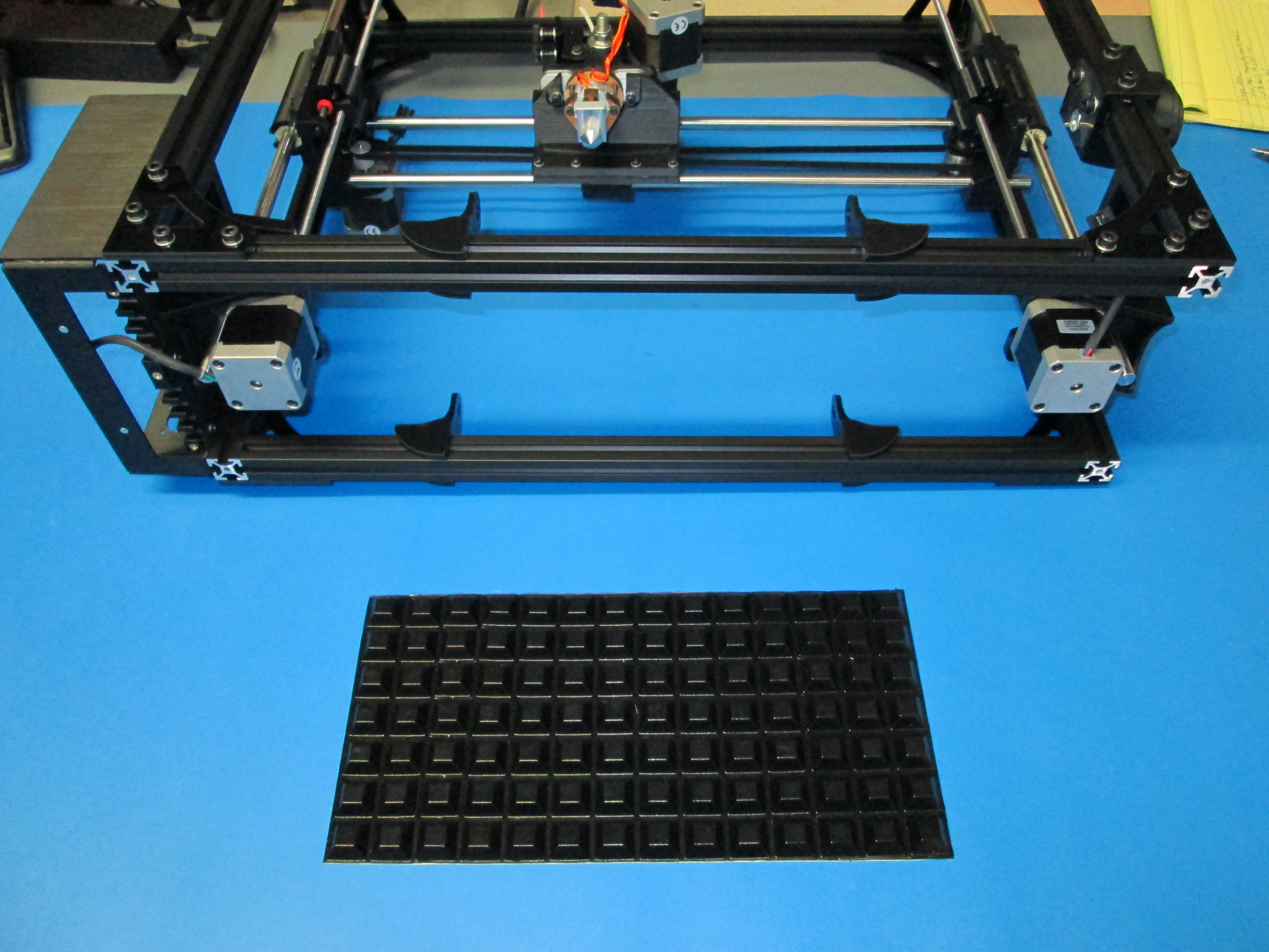
Install 4x rubber feet to bottom of frame.
Take note of location, do not cover bottom of vertical extrusion.
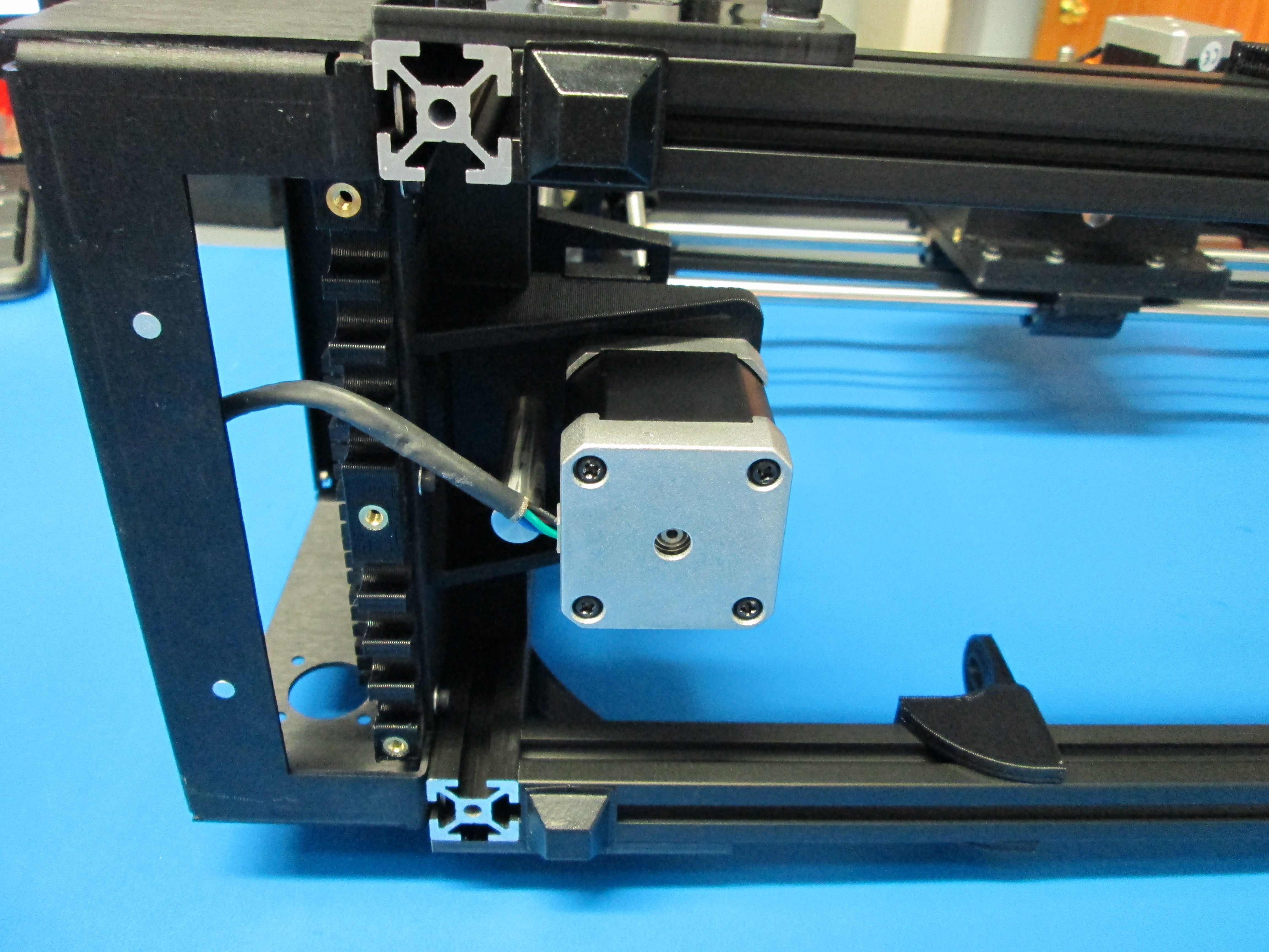
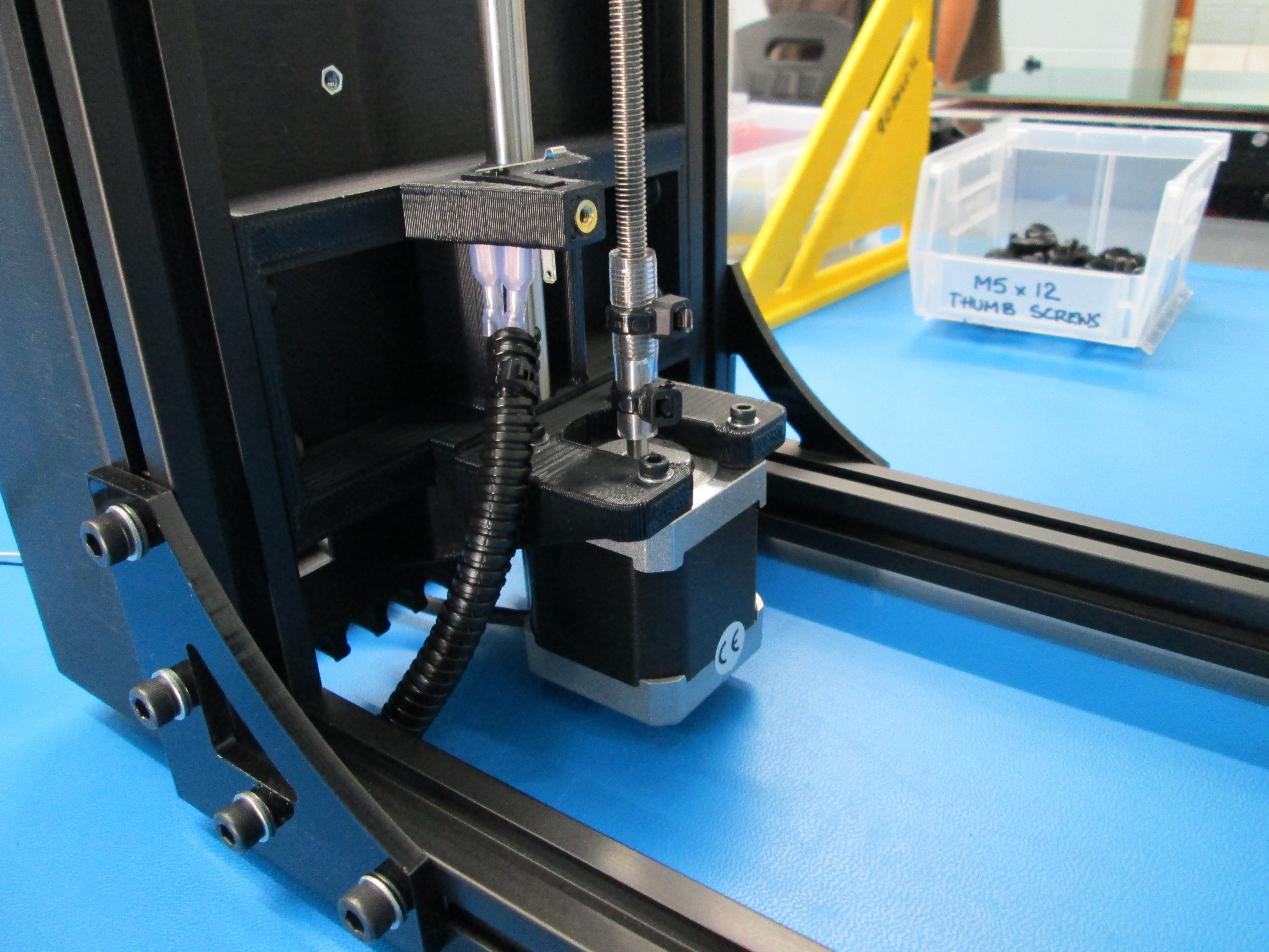
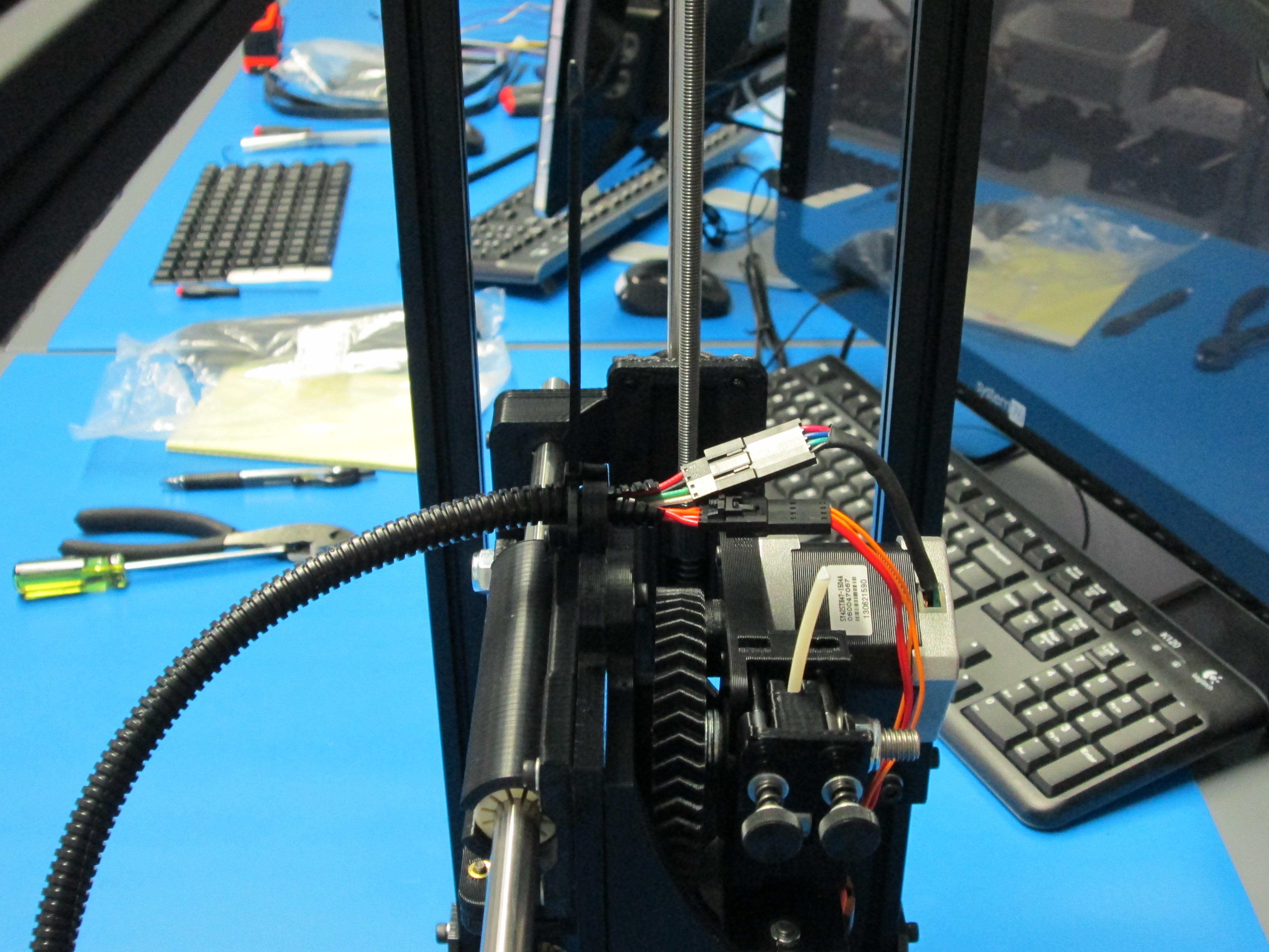
Route Z left motor wire through relief position #5.
Plug into the board in location shown.
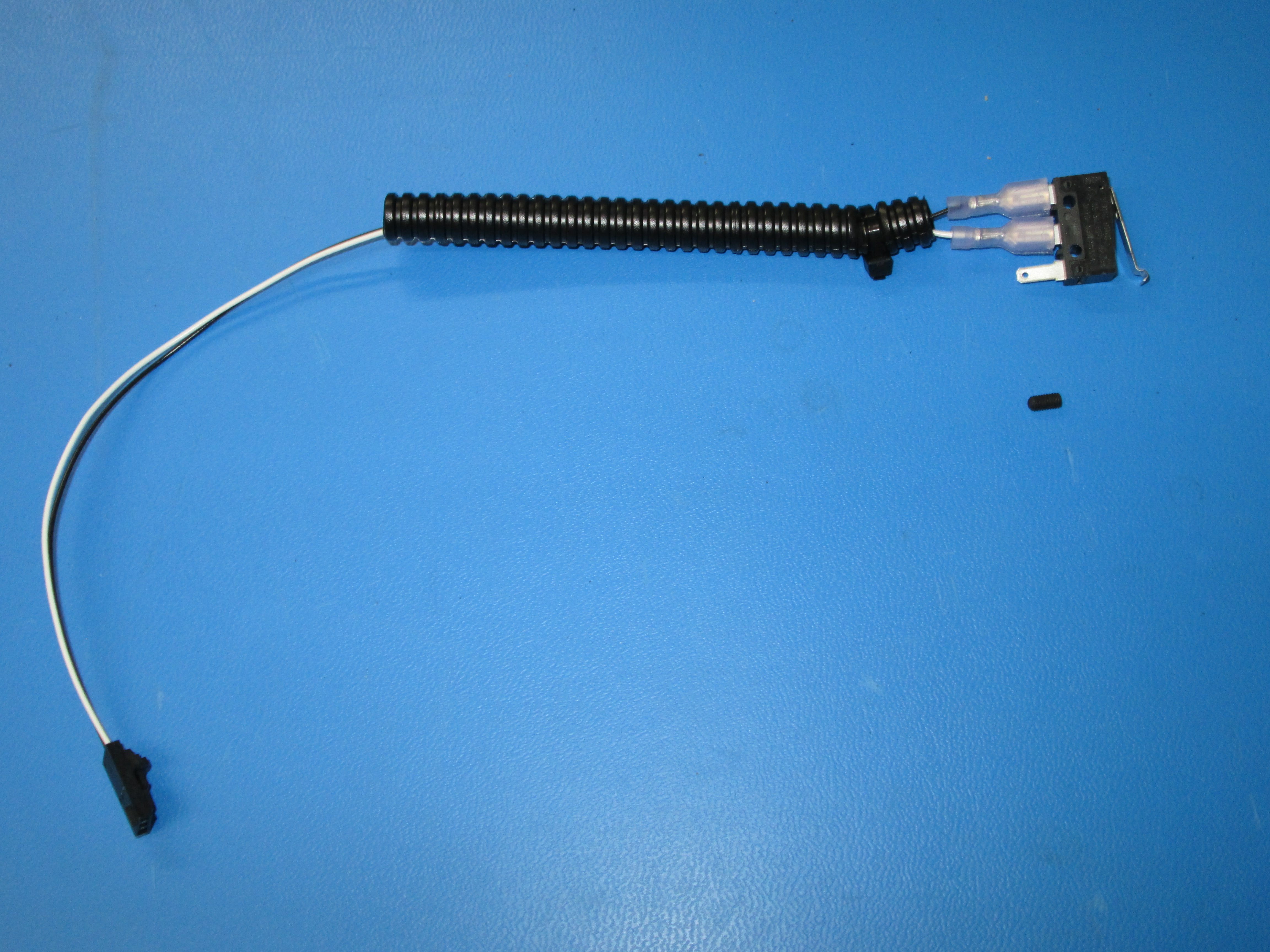
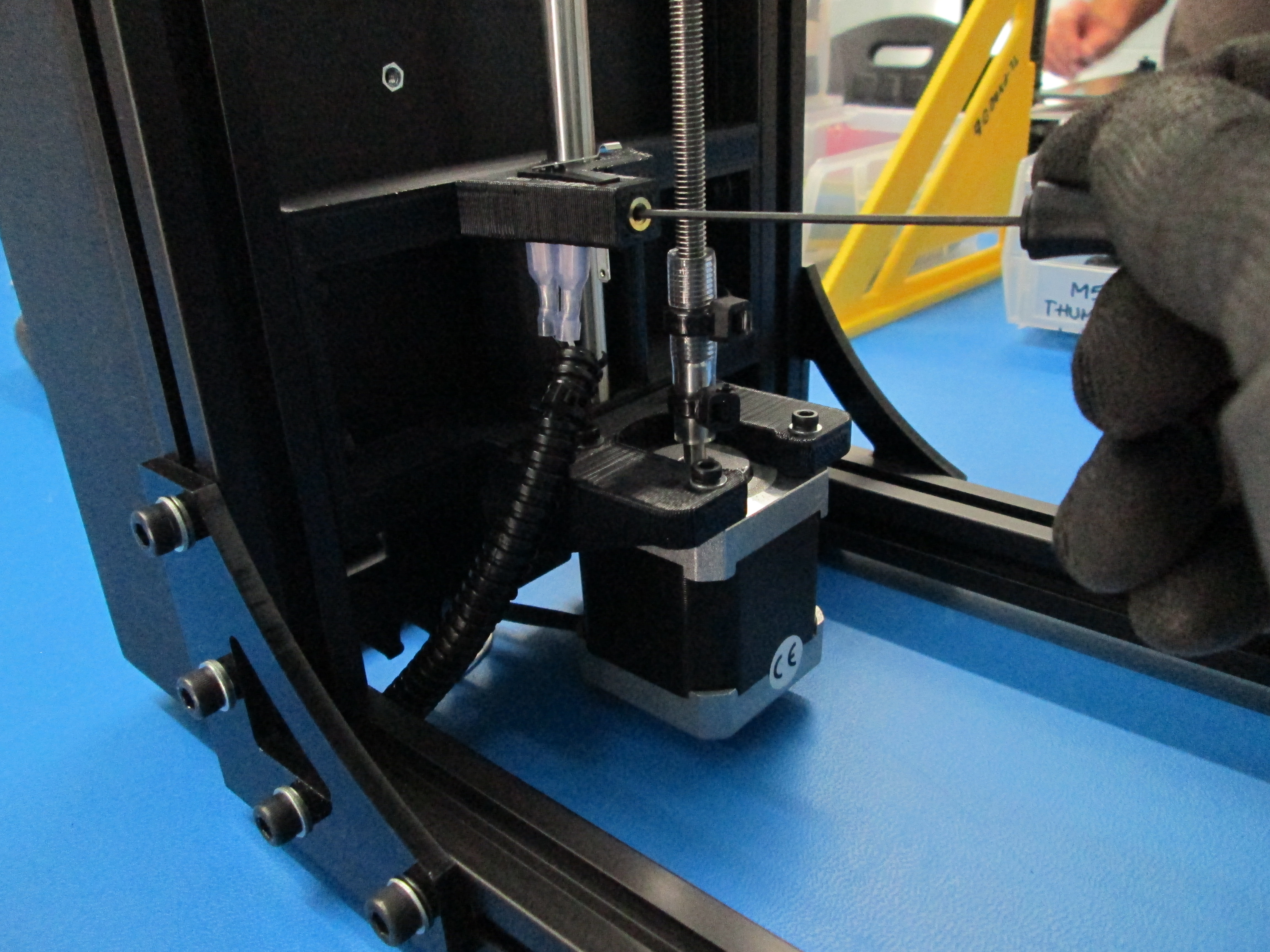
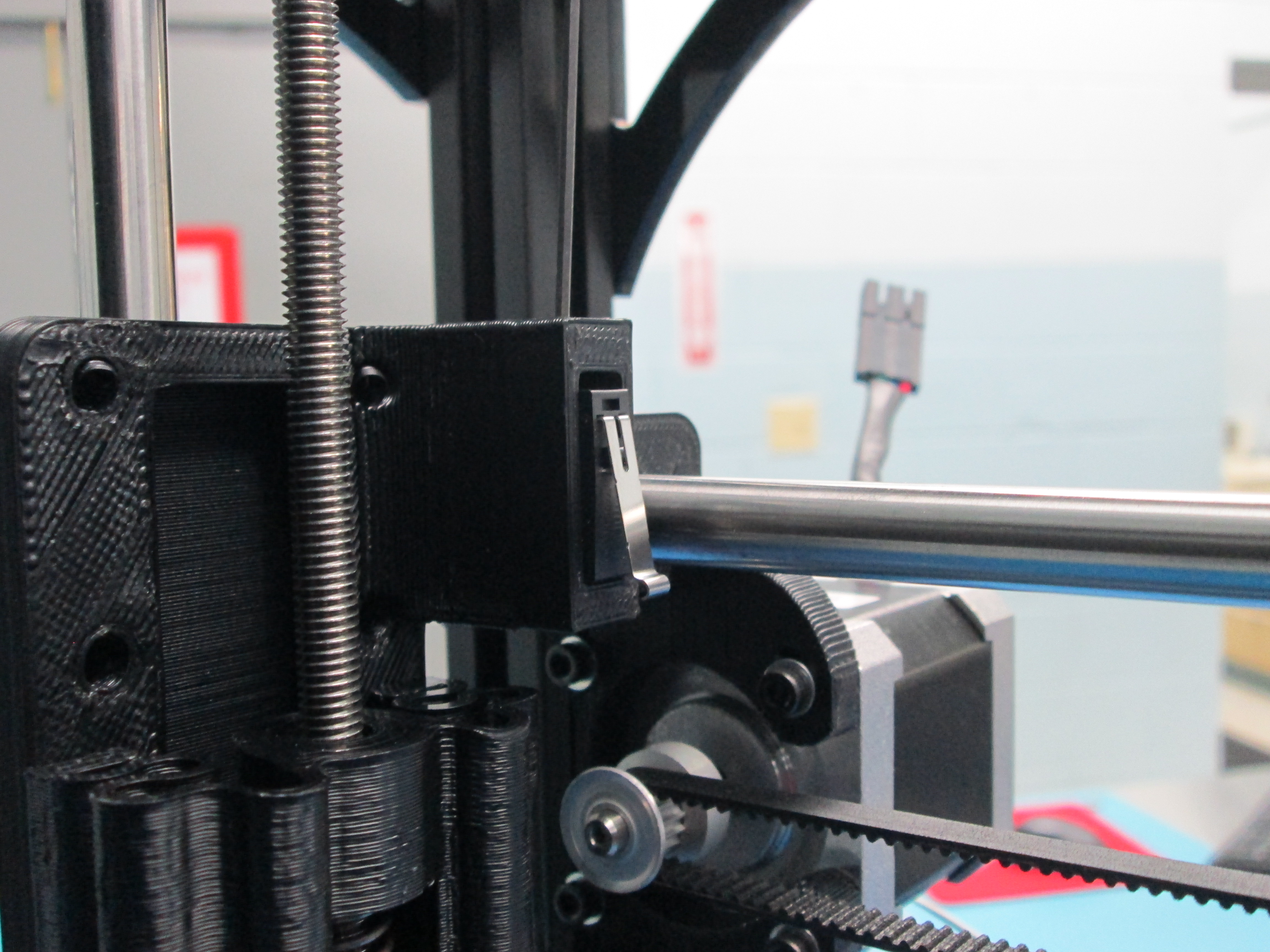
Install switch as shown and secure with a M3 x 6 set screw.
Route wires through relief #6 and plug in as shown.
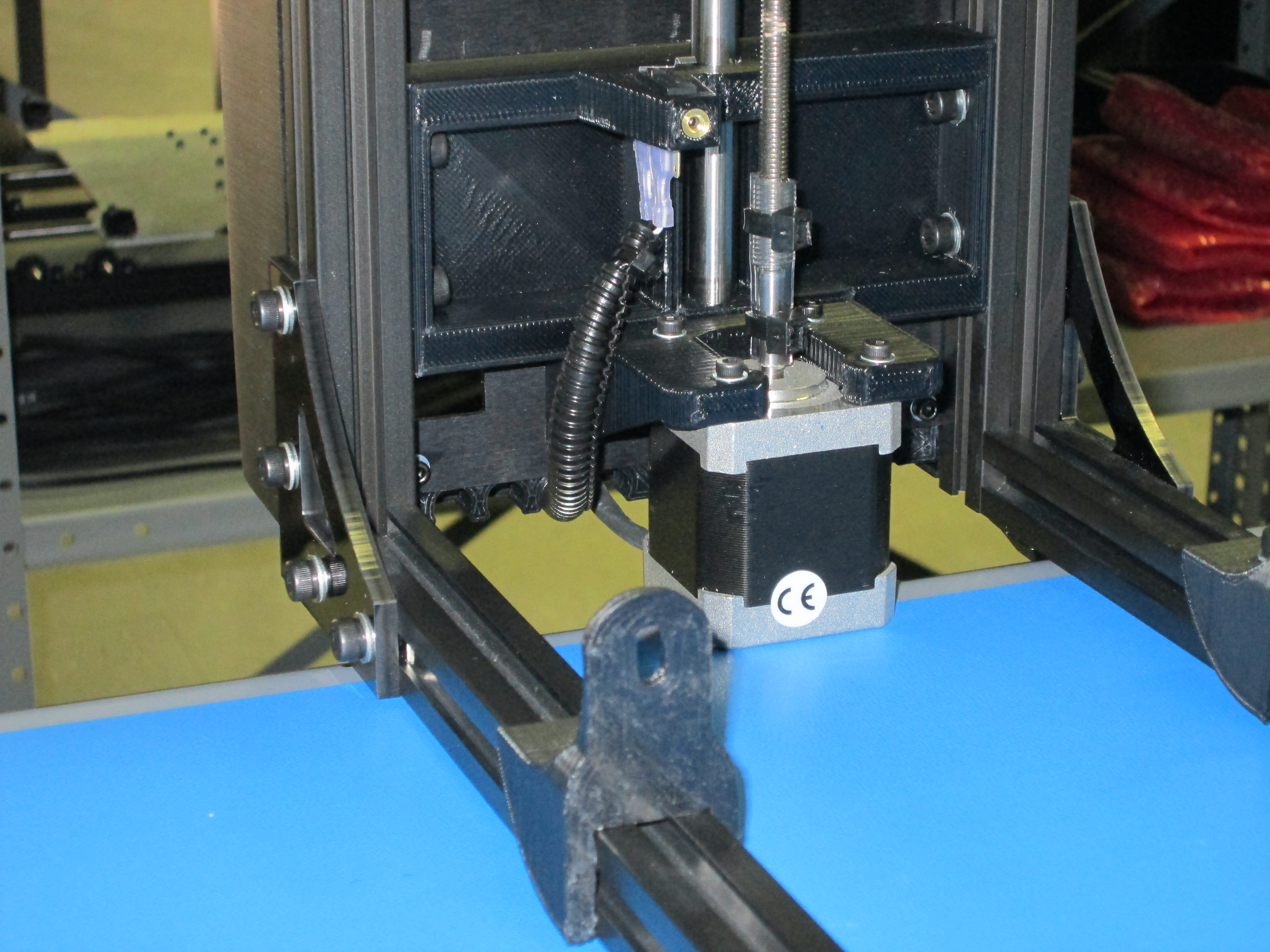
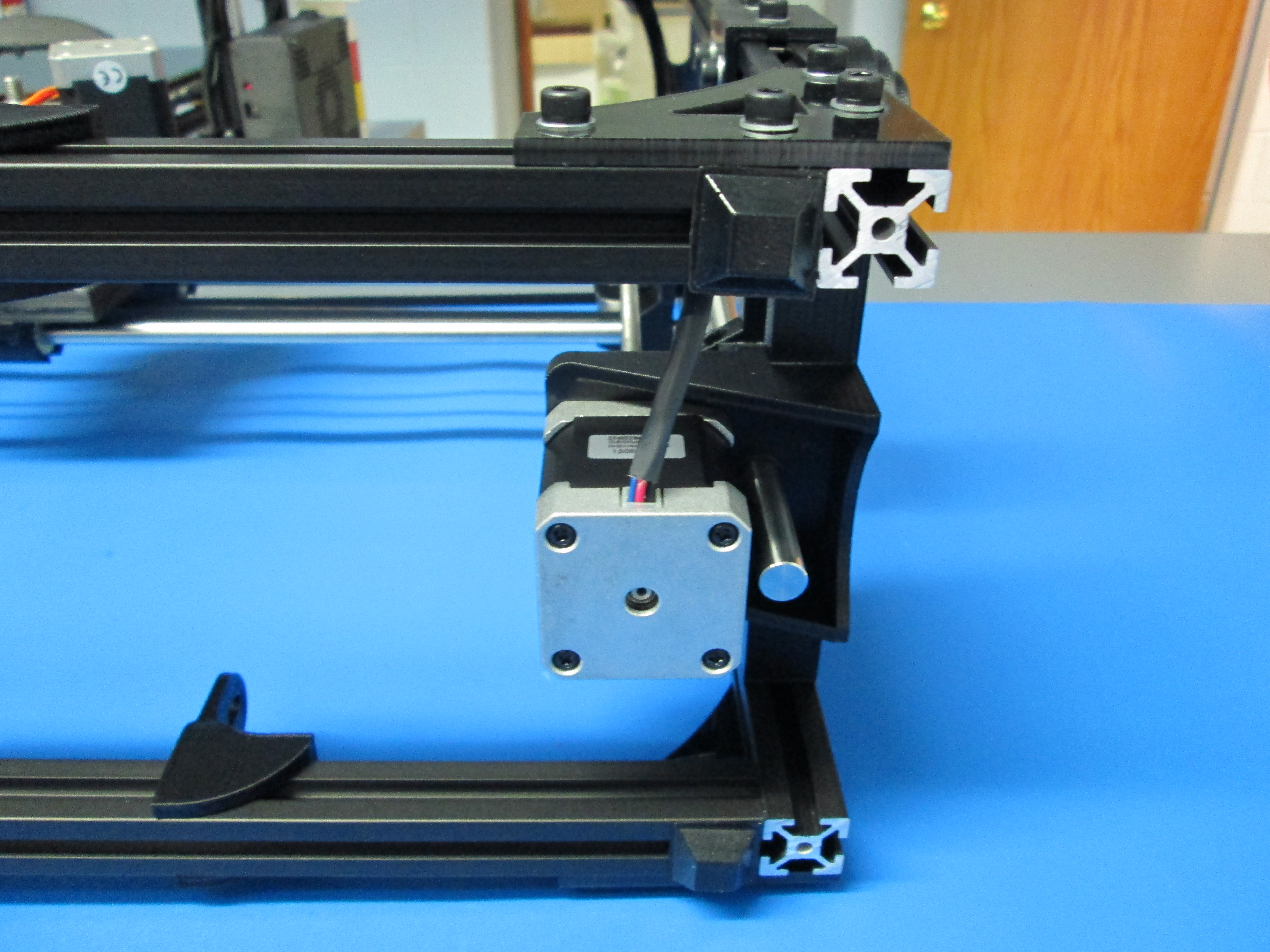
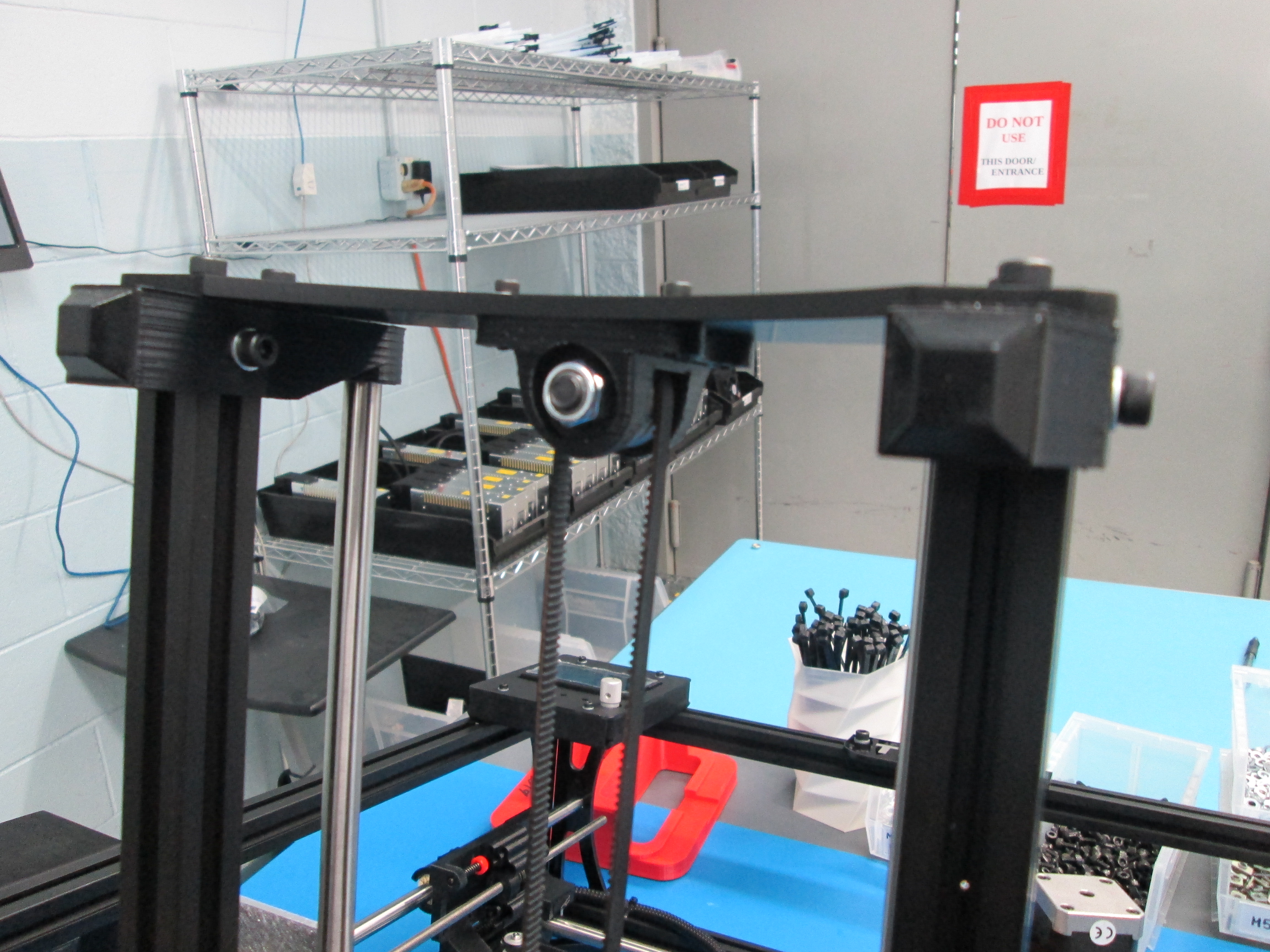
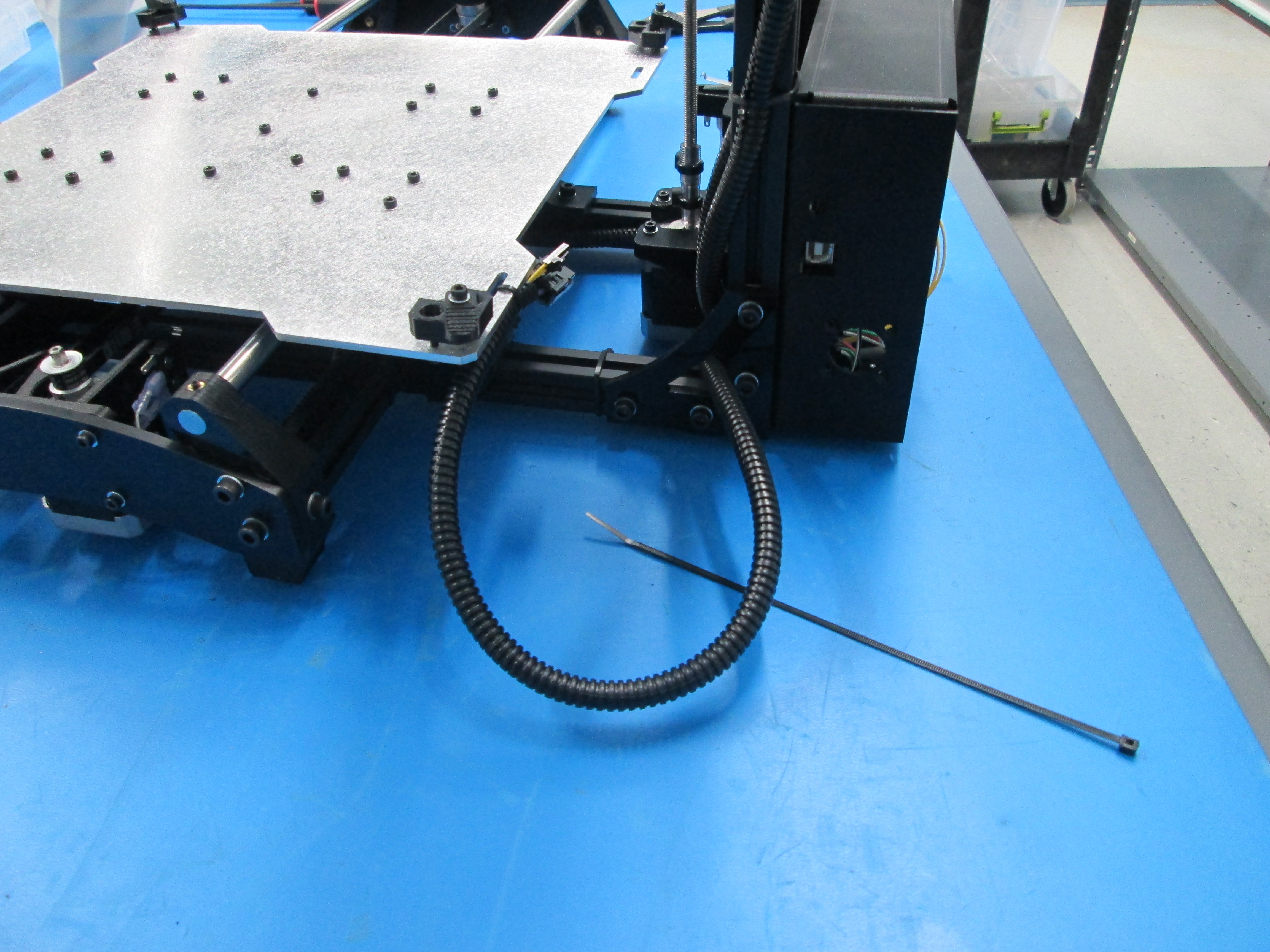
Connect the Z motor extension to the right Z motor.
Route the extension through relief position #8.
Plug in as shown and put ground lug on post.
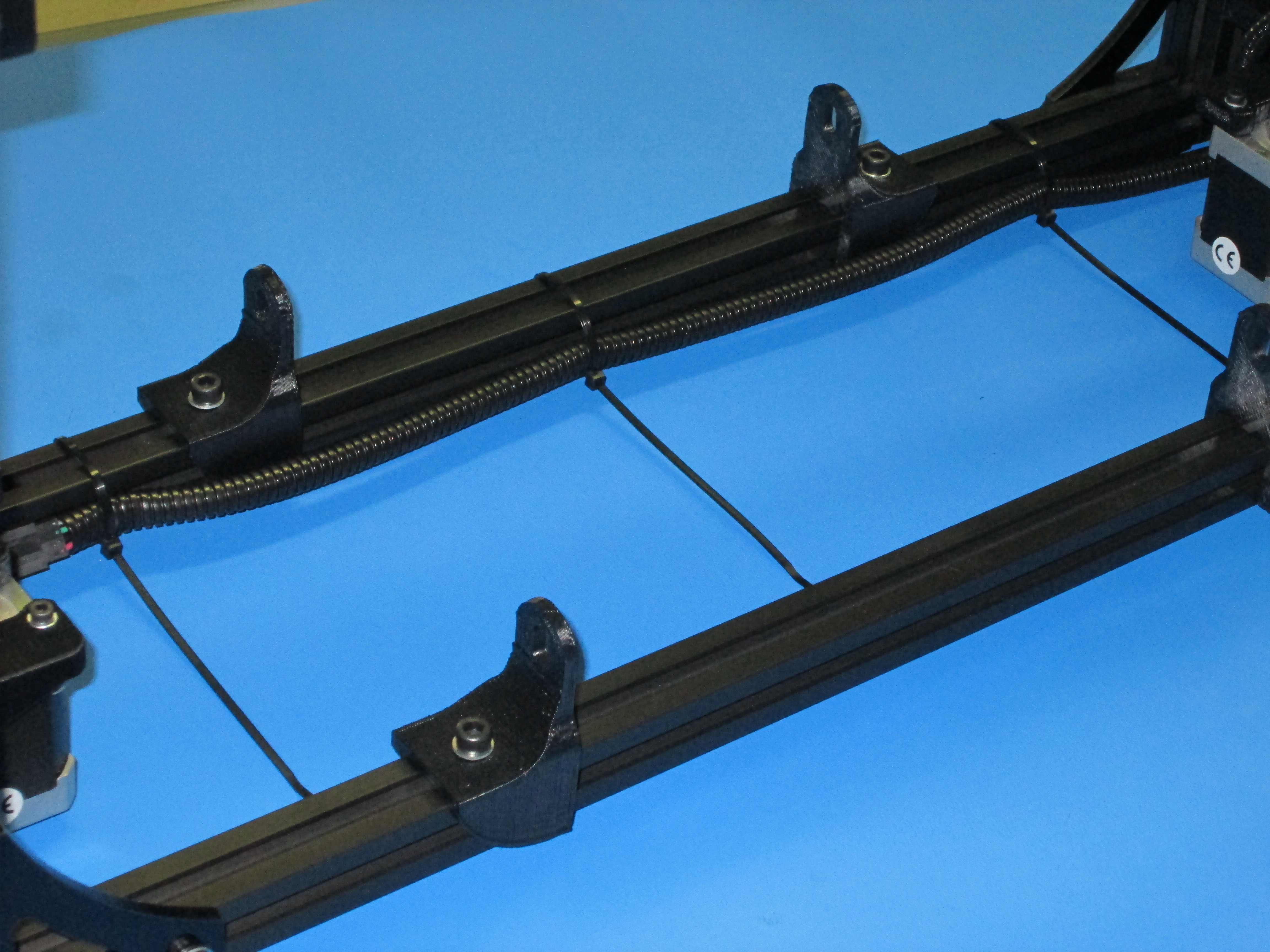
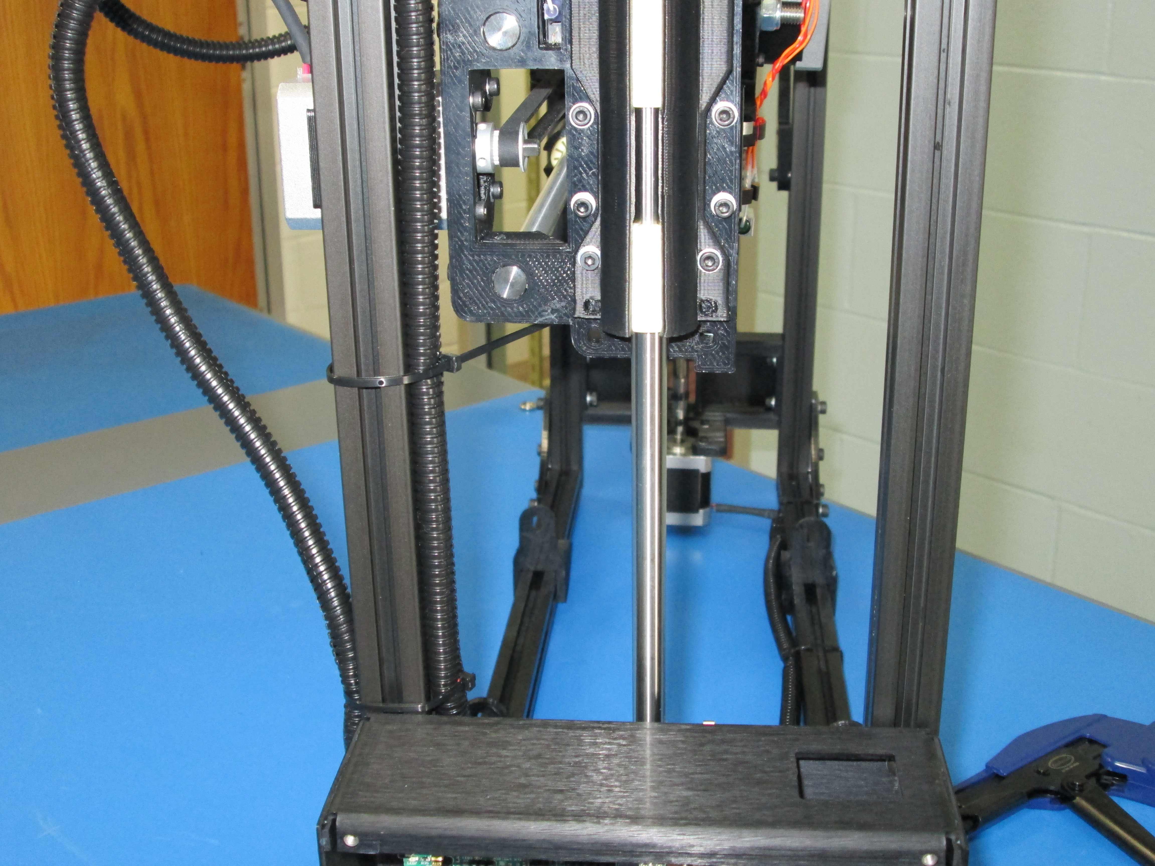
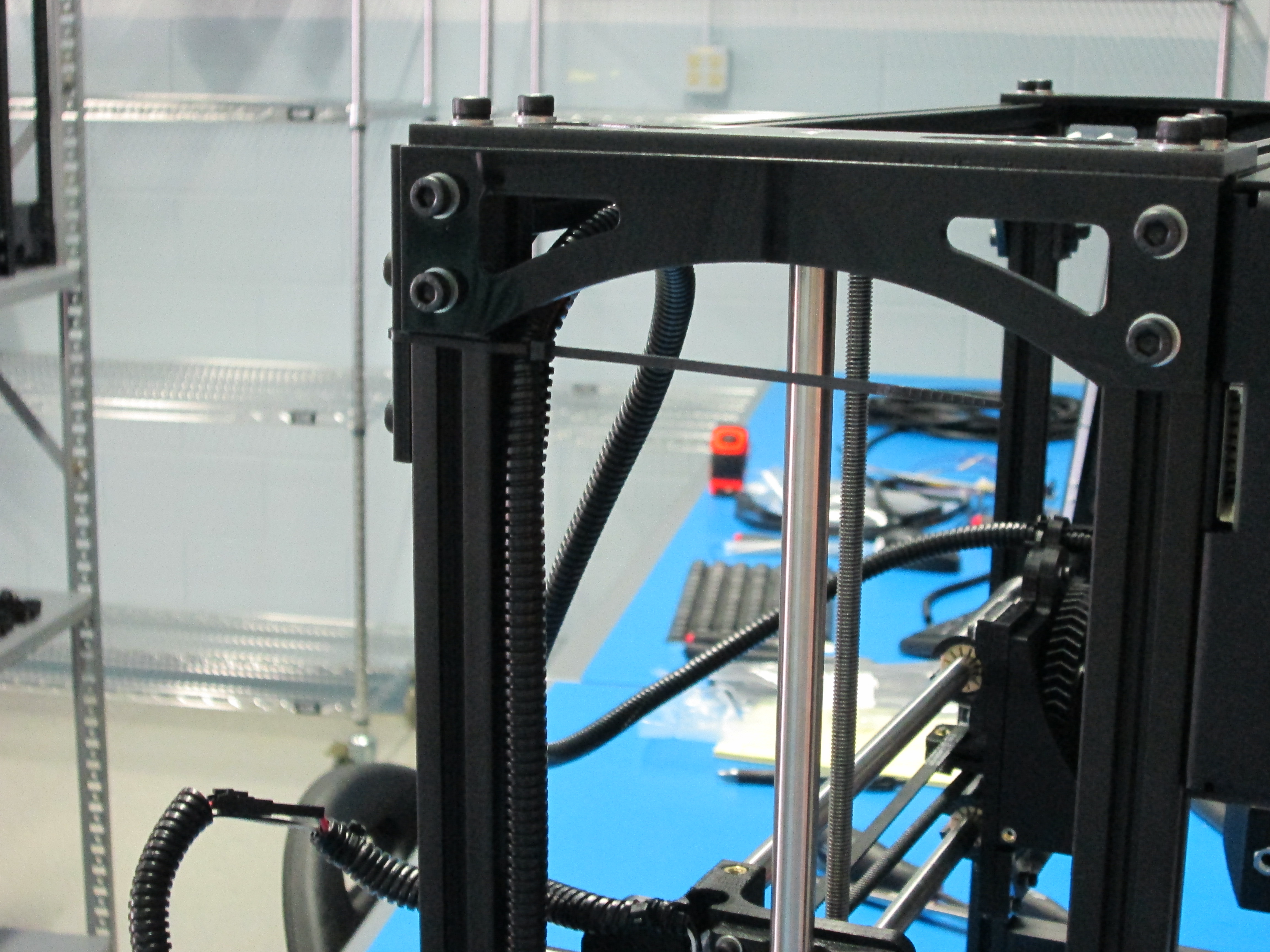
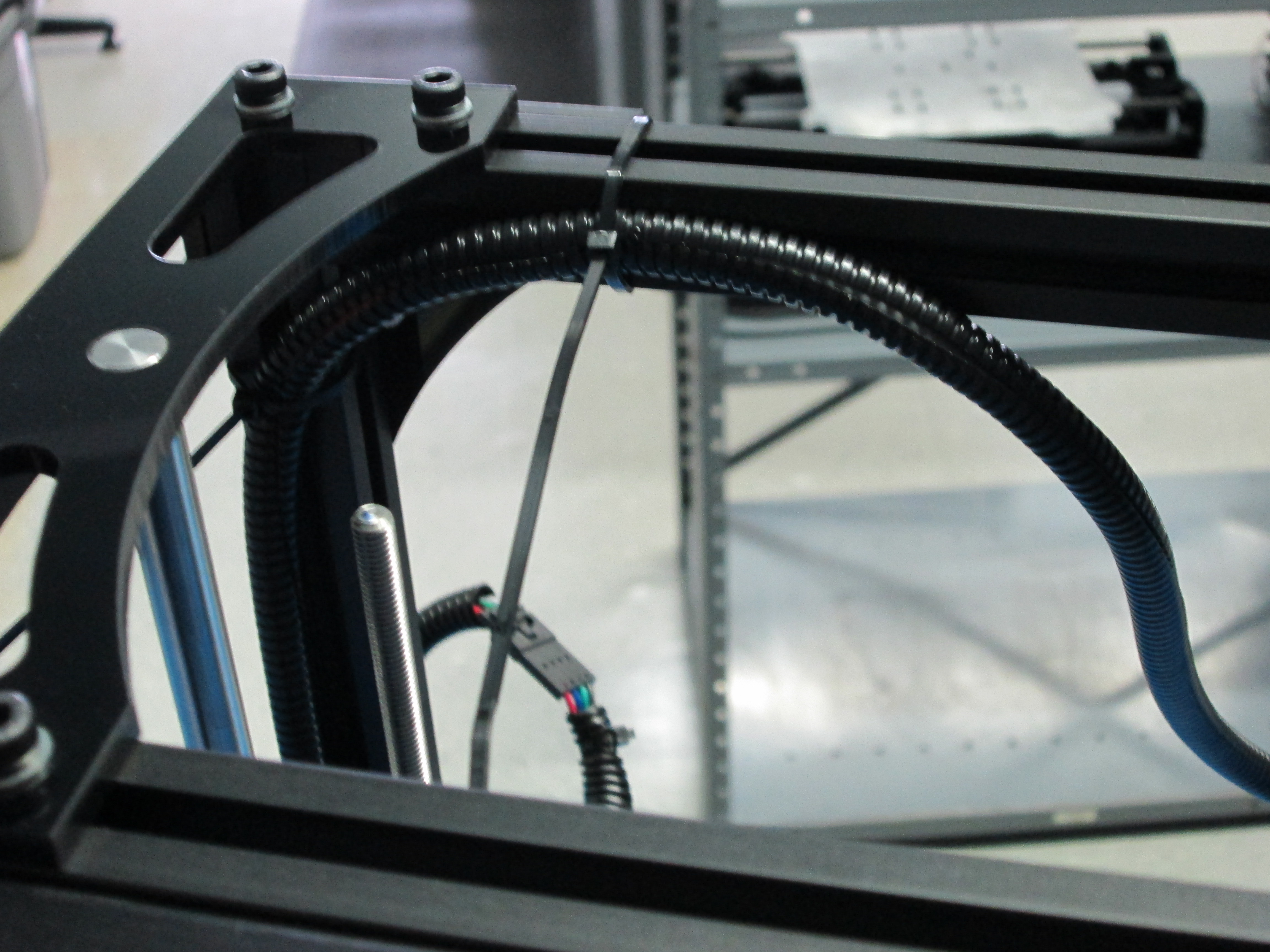
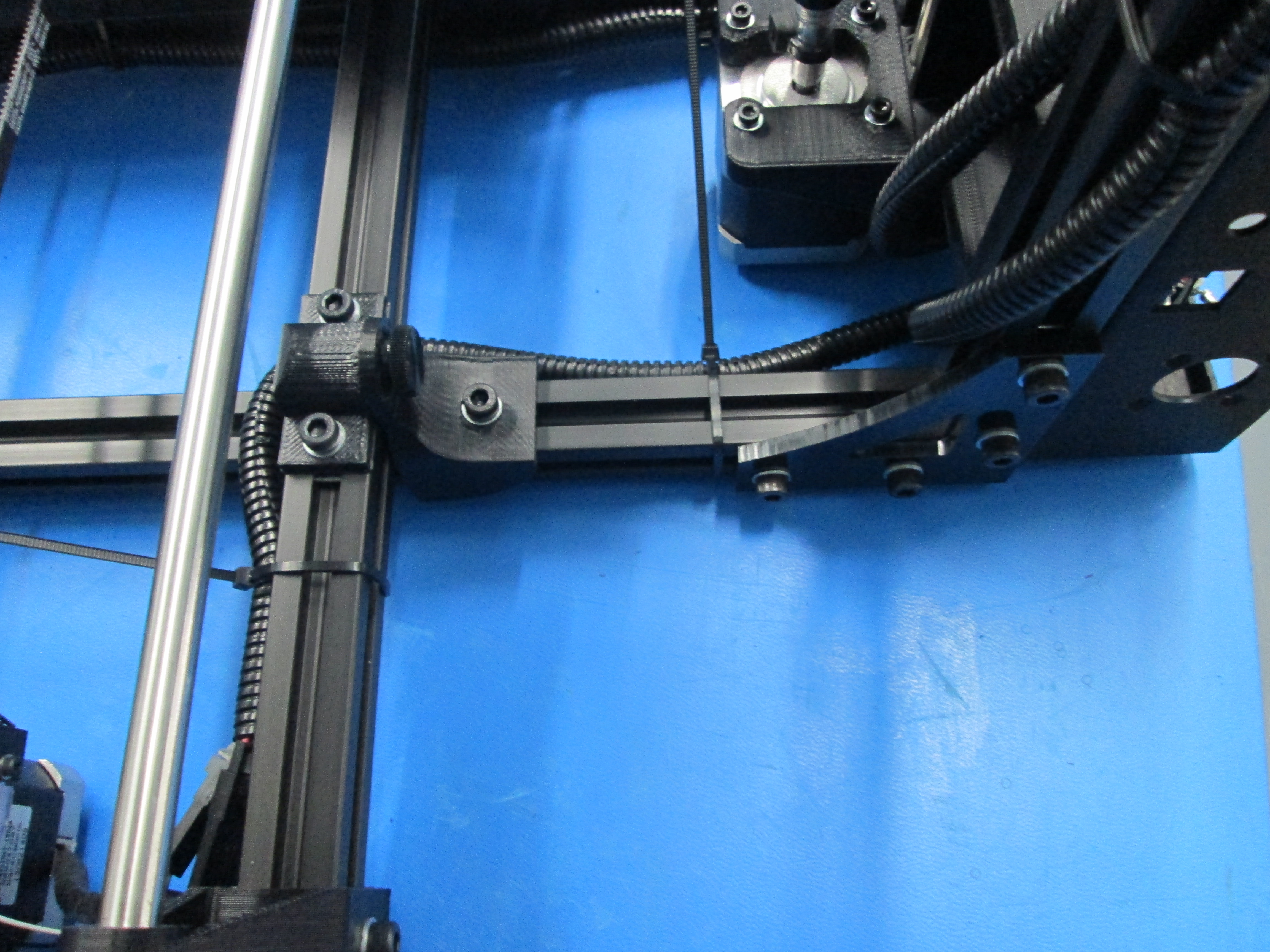
Zip tie at the 3 locations indicated while removing slack.
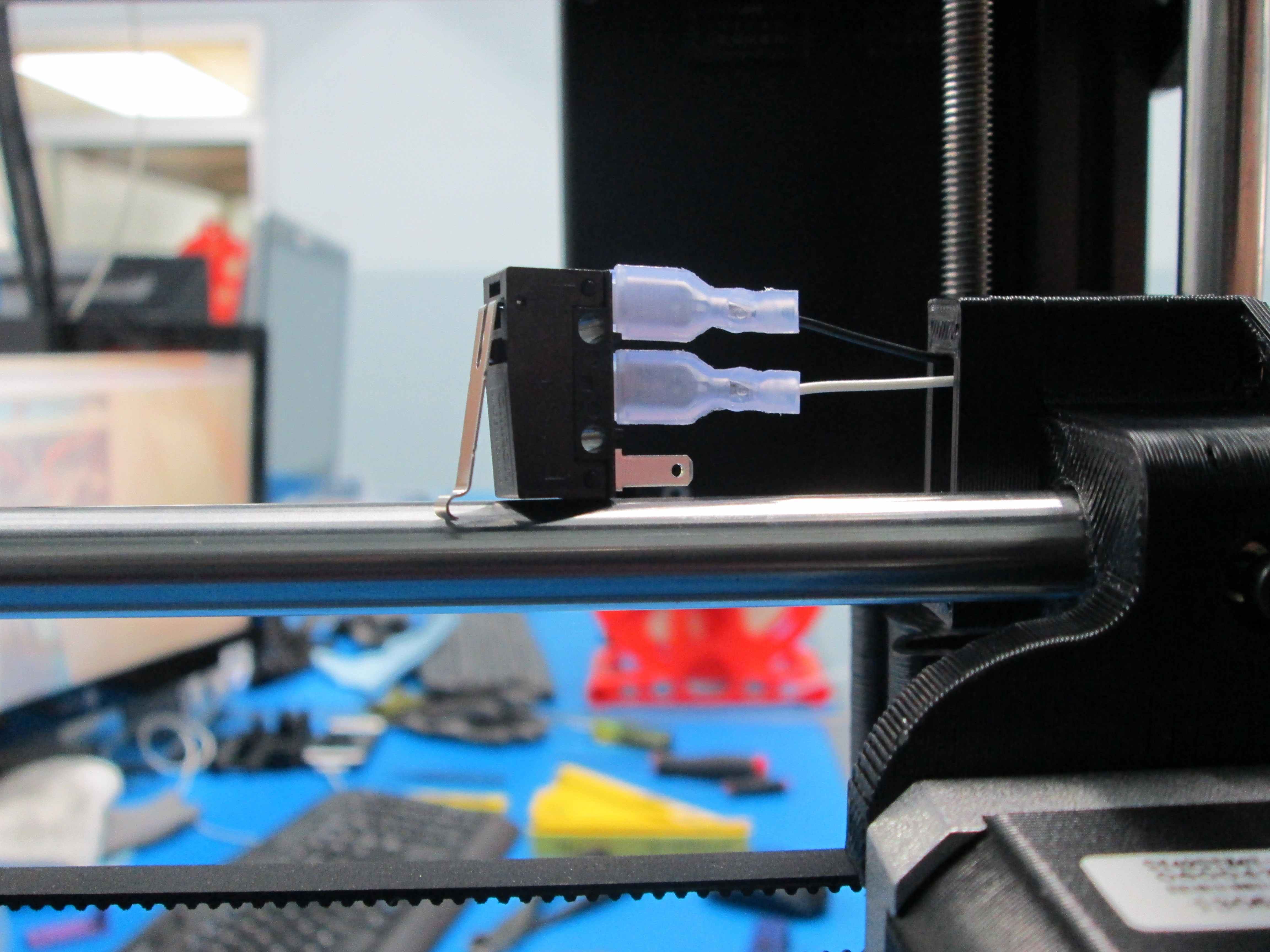
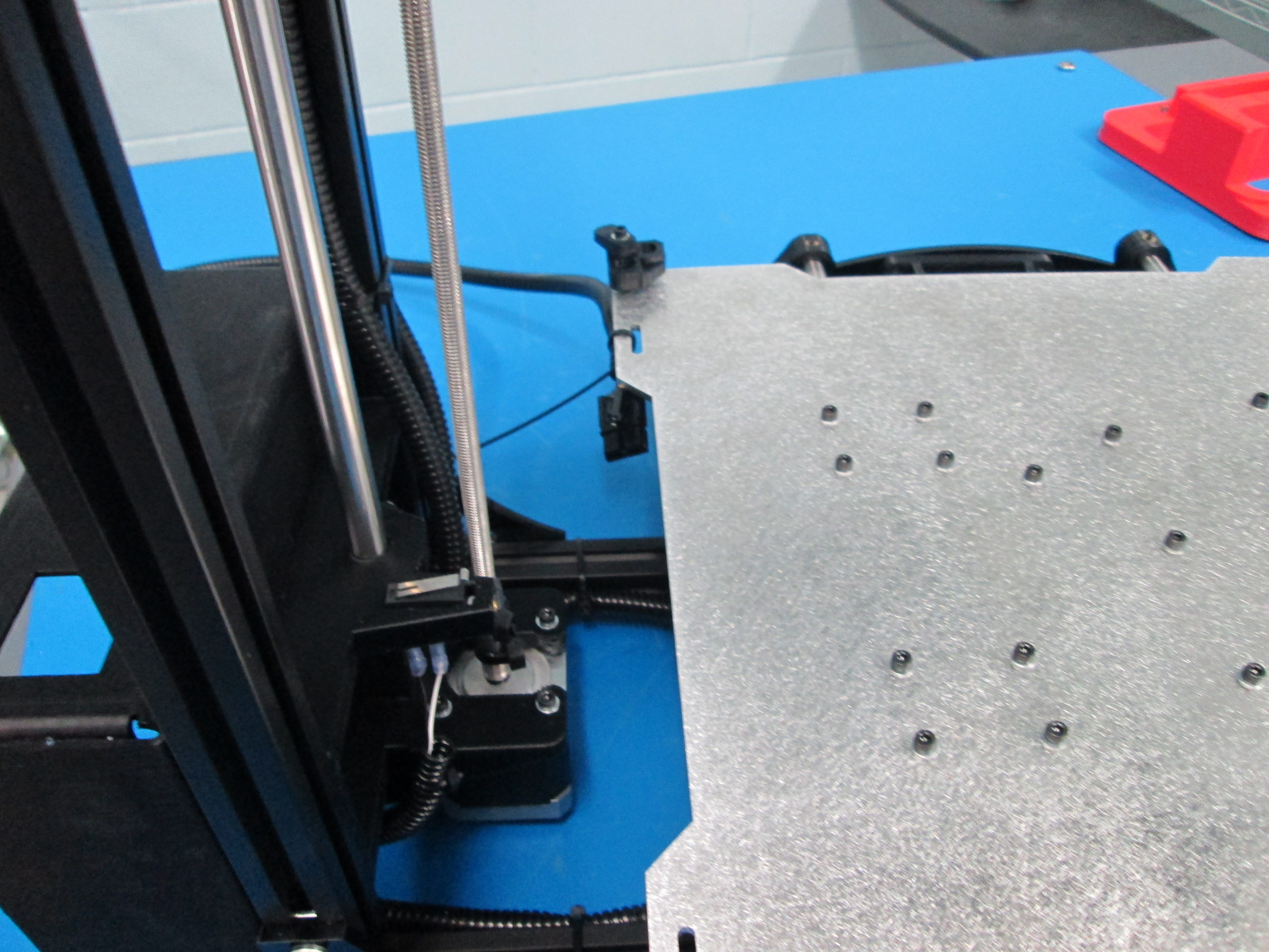
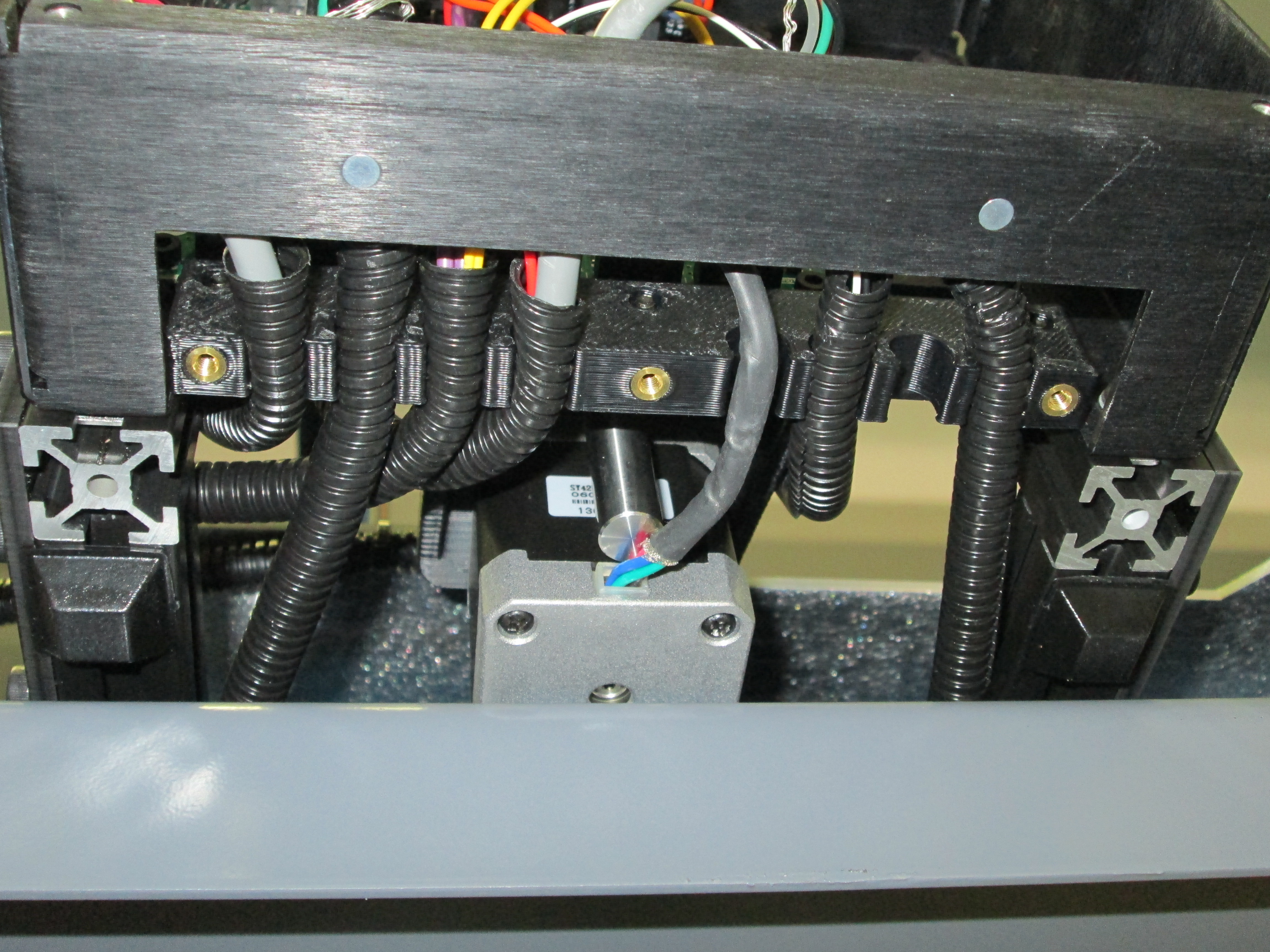
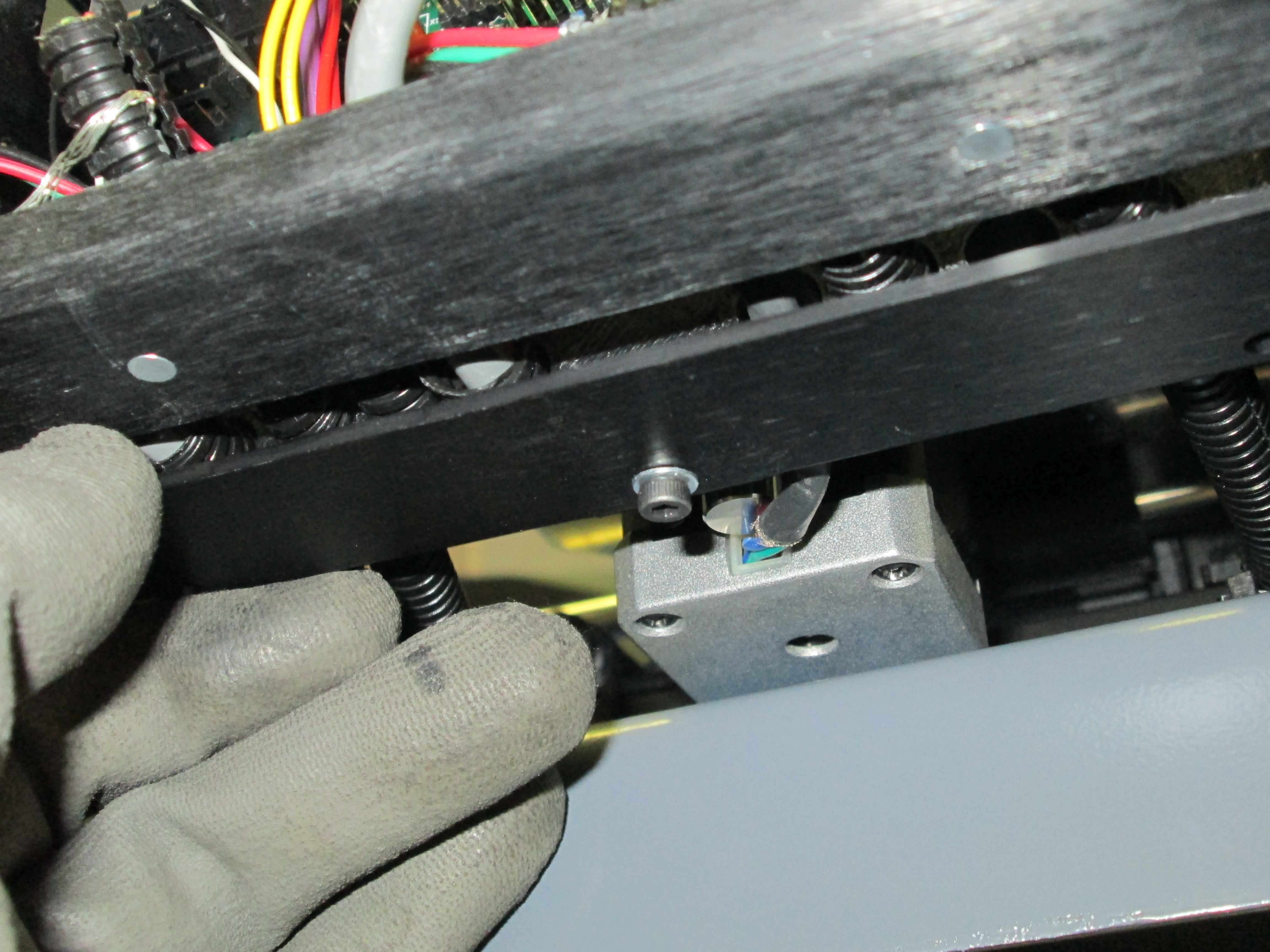
Route switch extension wires though X end motor mount.
Plug switch extension wires onto limit switch.
Secure with set screw.
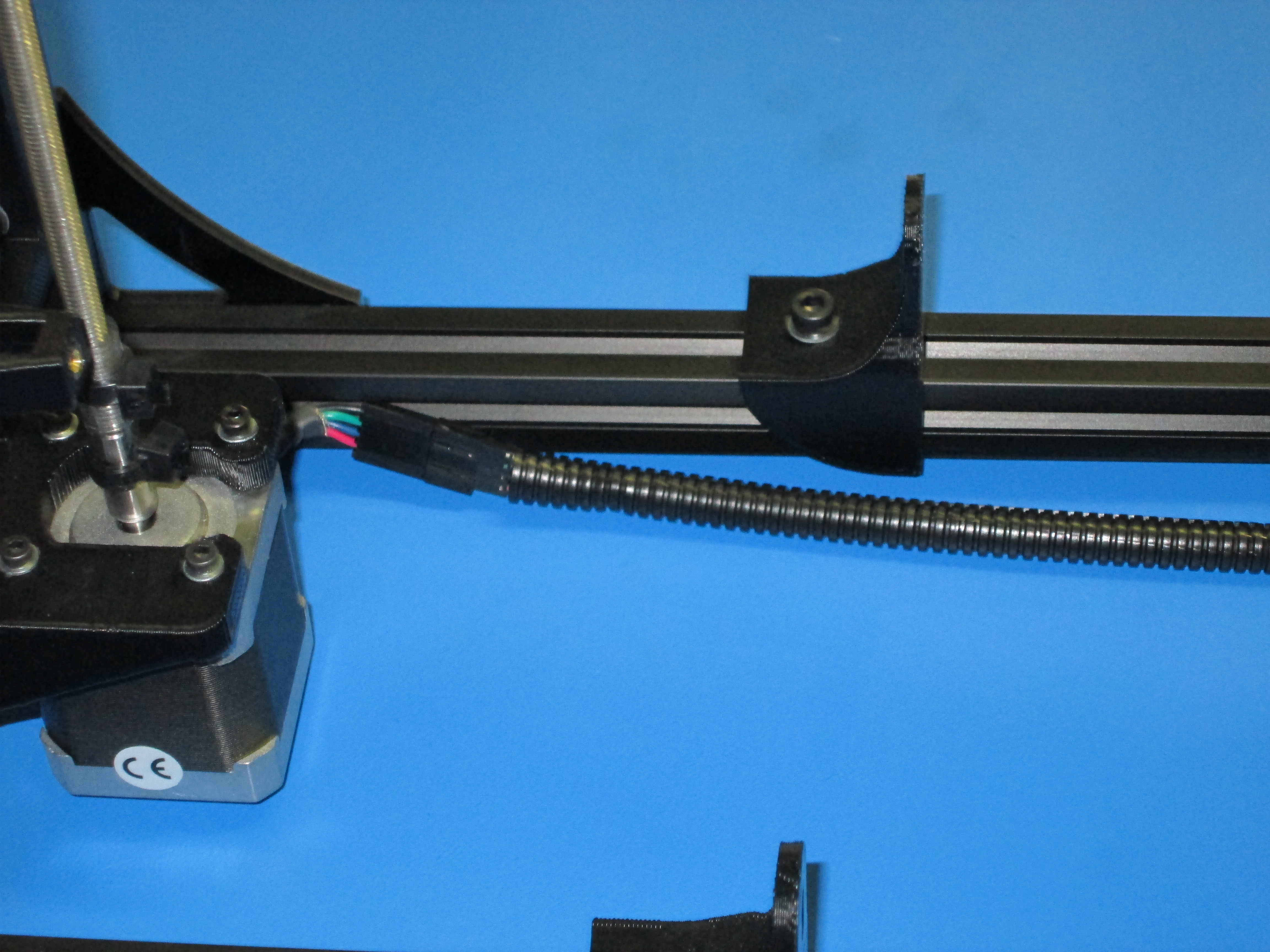
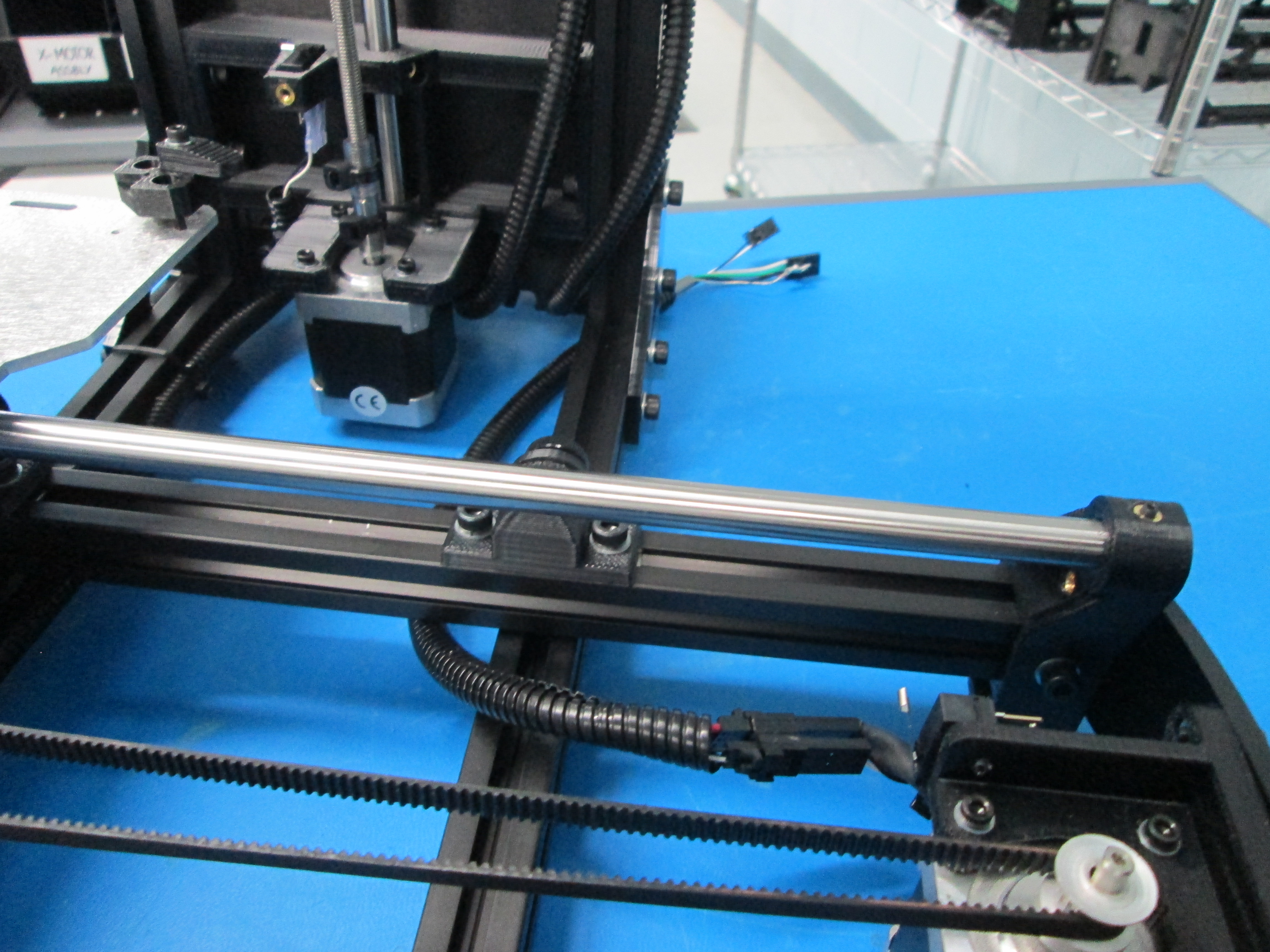
Plug in X-motor wire.
Zip tie one end of the extension to the motor mount as shown. Zip tie the other end to the plug.
Route wires through relief position # 1
Plug in wires as shown and put ground lug onto post.

Fasten end of wires to cutout in print carriage
Route wires on inside of extrusion
Route through strain relief #4
Plug in as shown and put ground lug on post
Zip tie as shown

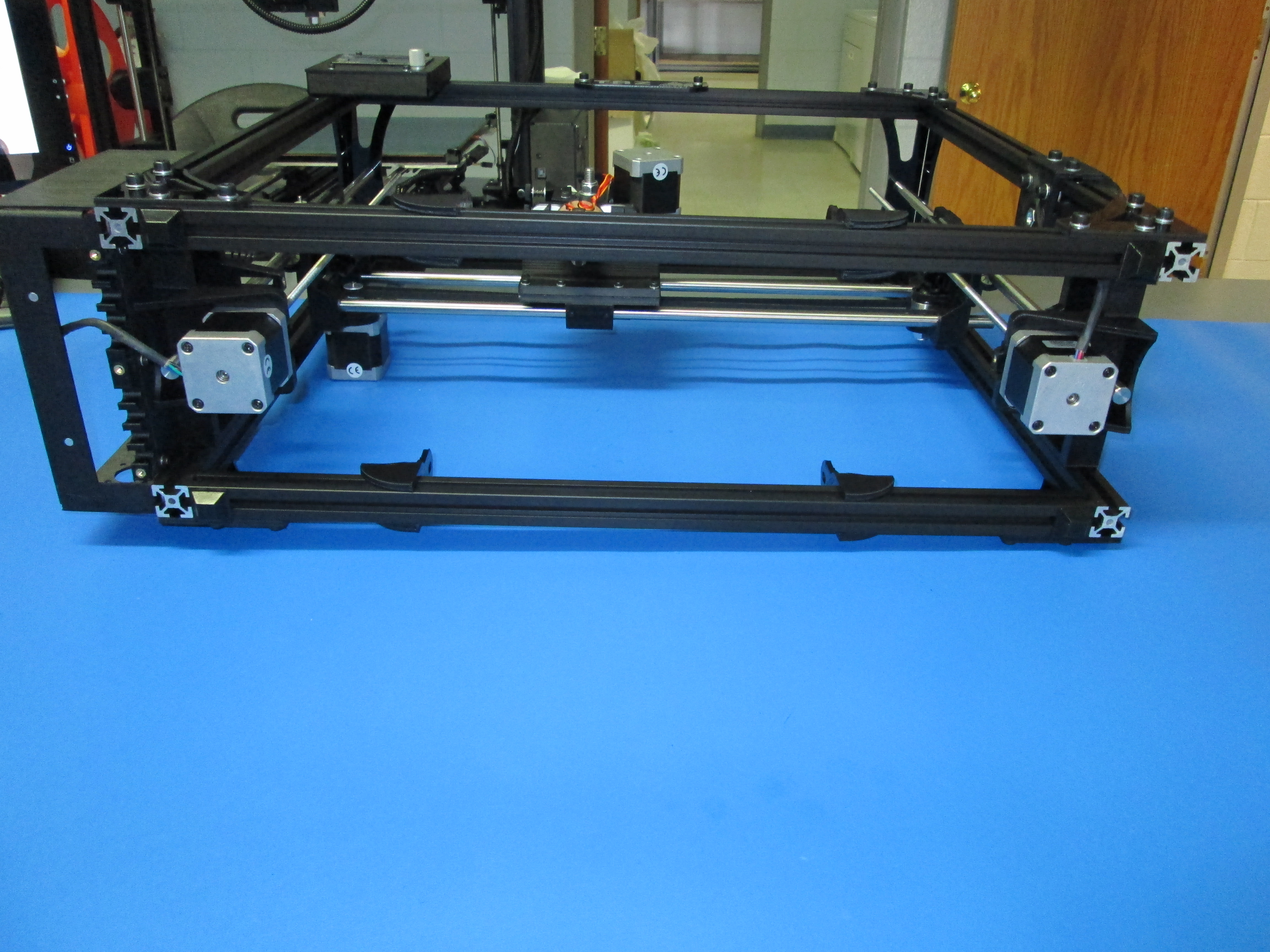
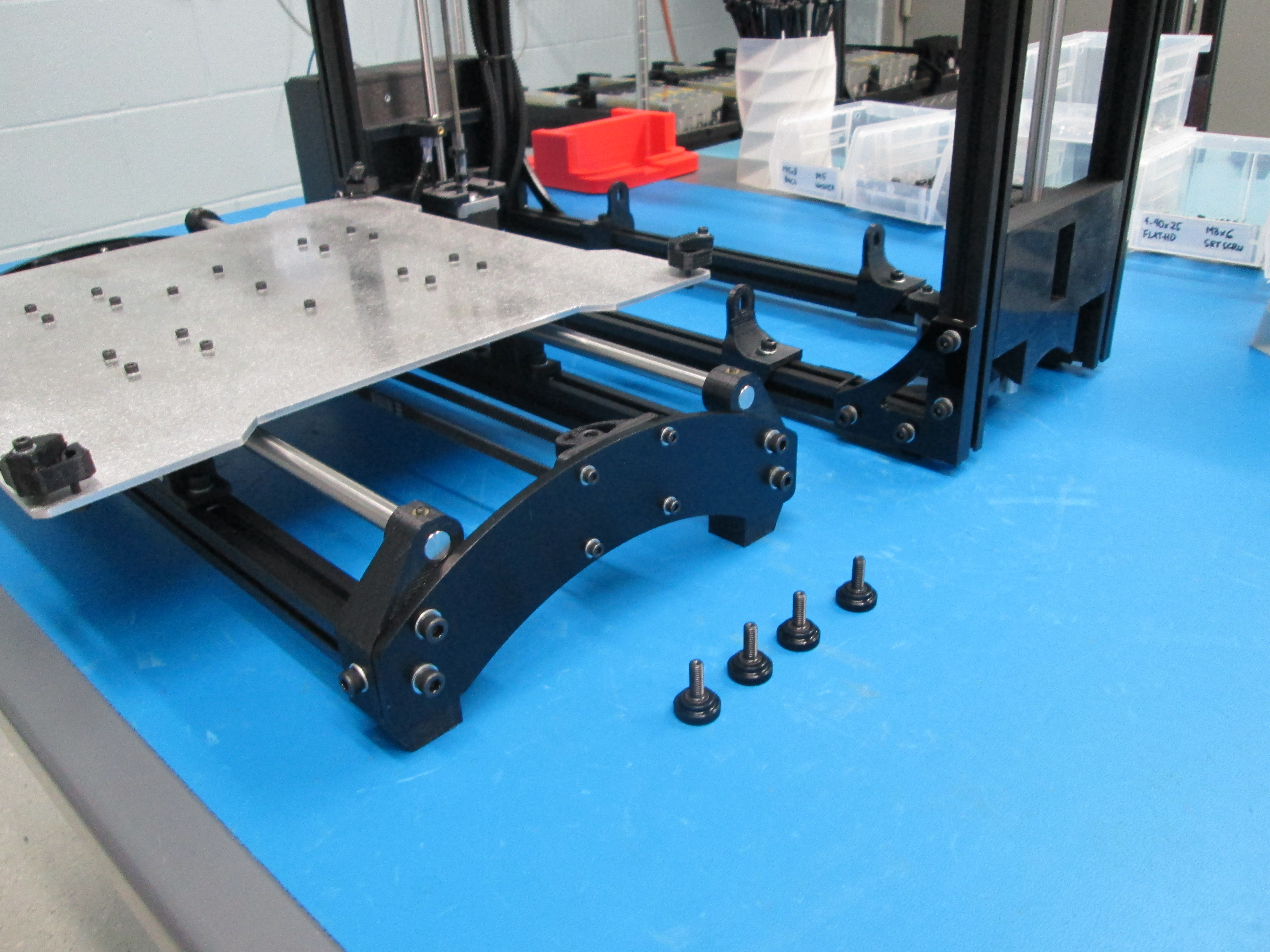
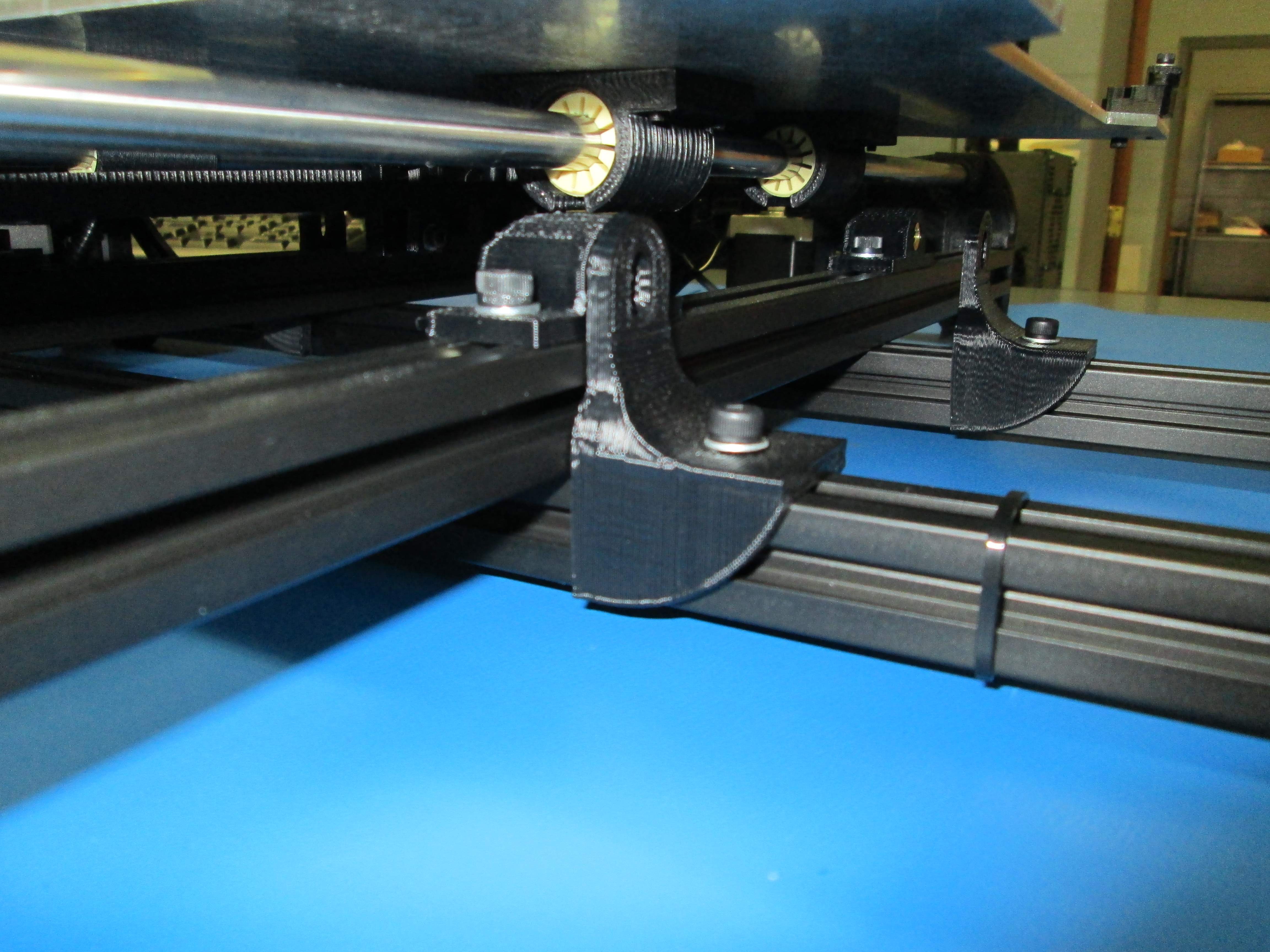
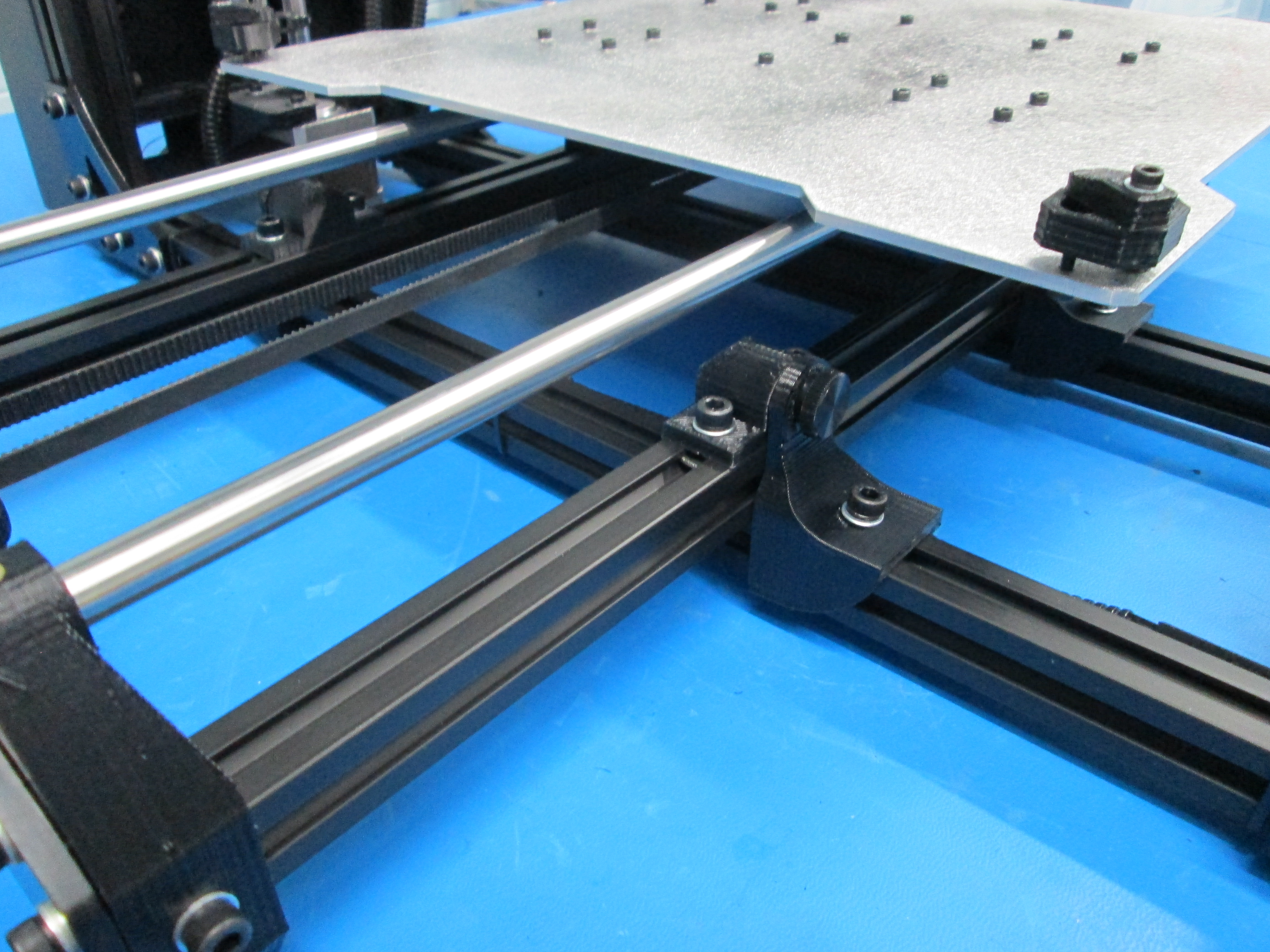
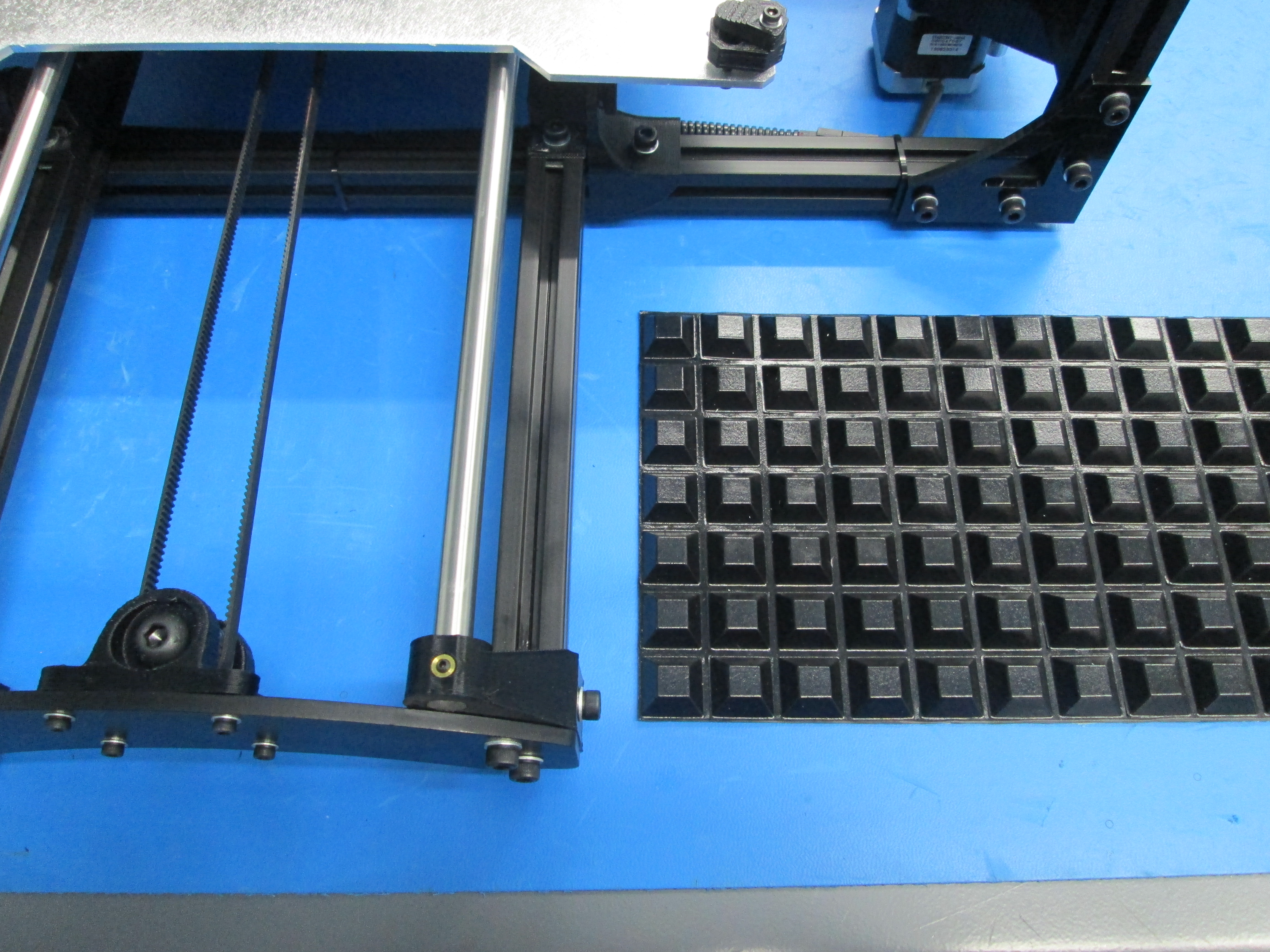
Loosen Y table mounts and Y mount chassis to allow for adjustment
Install thumbscrews
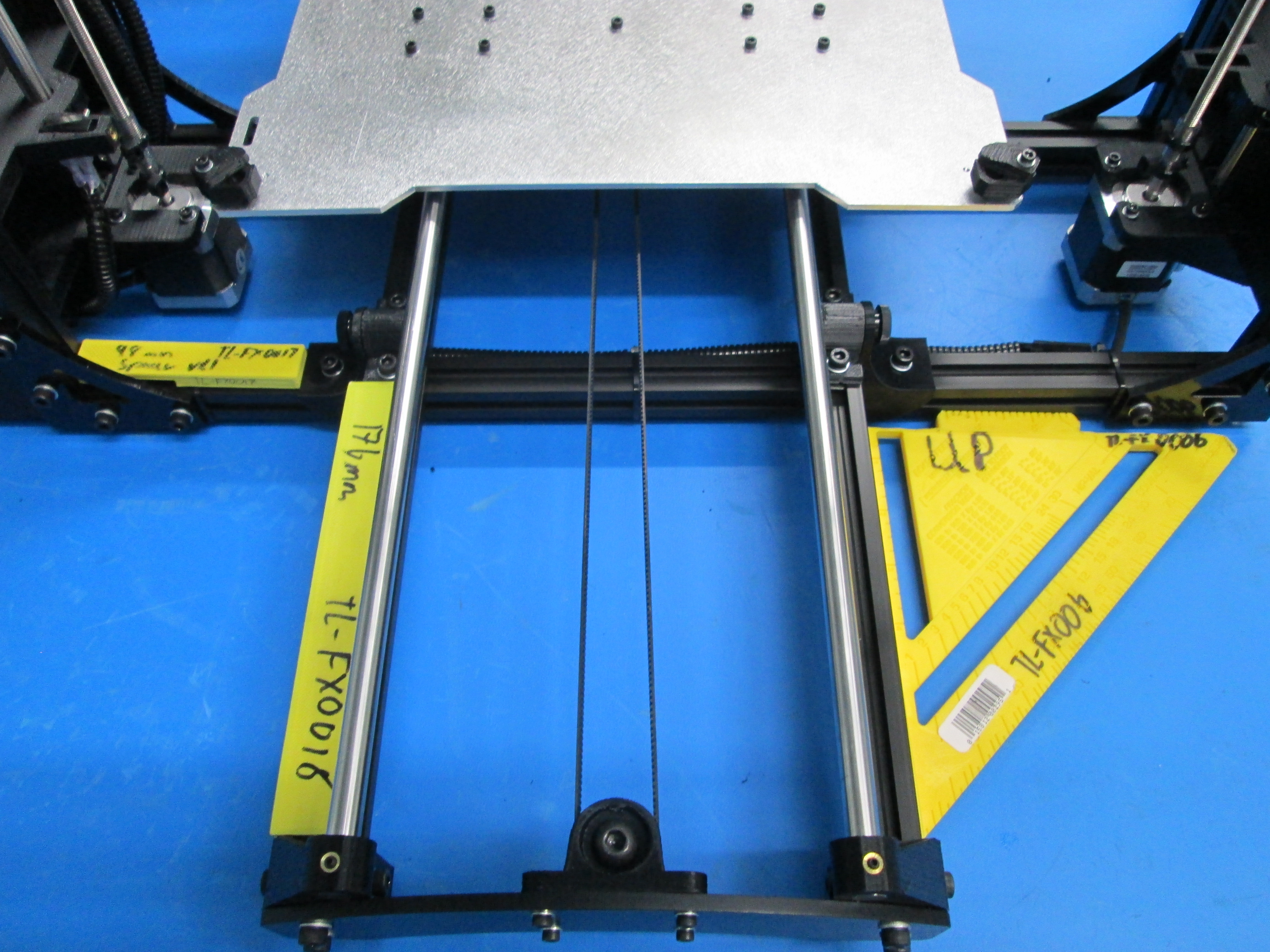
Square frame using fixtures
Tighten Y table mounts, Y mount chassis and thumbscrews (Don't over-tighten thumbscrews as they are disassembled for shipping)
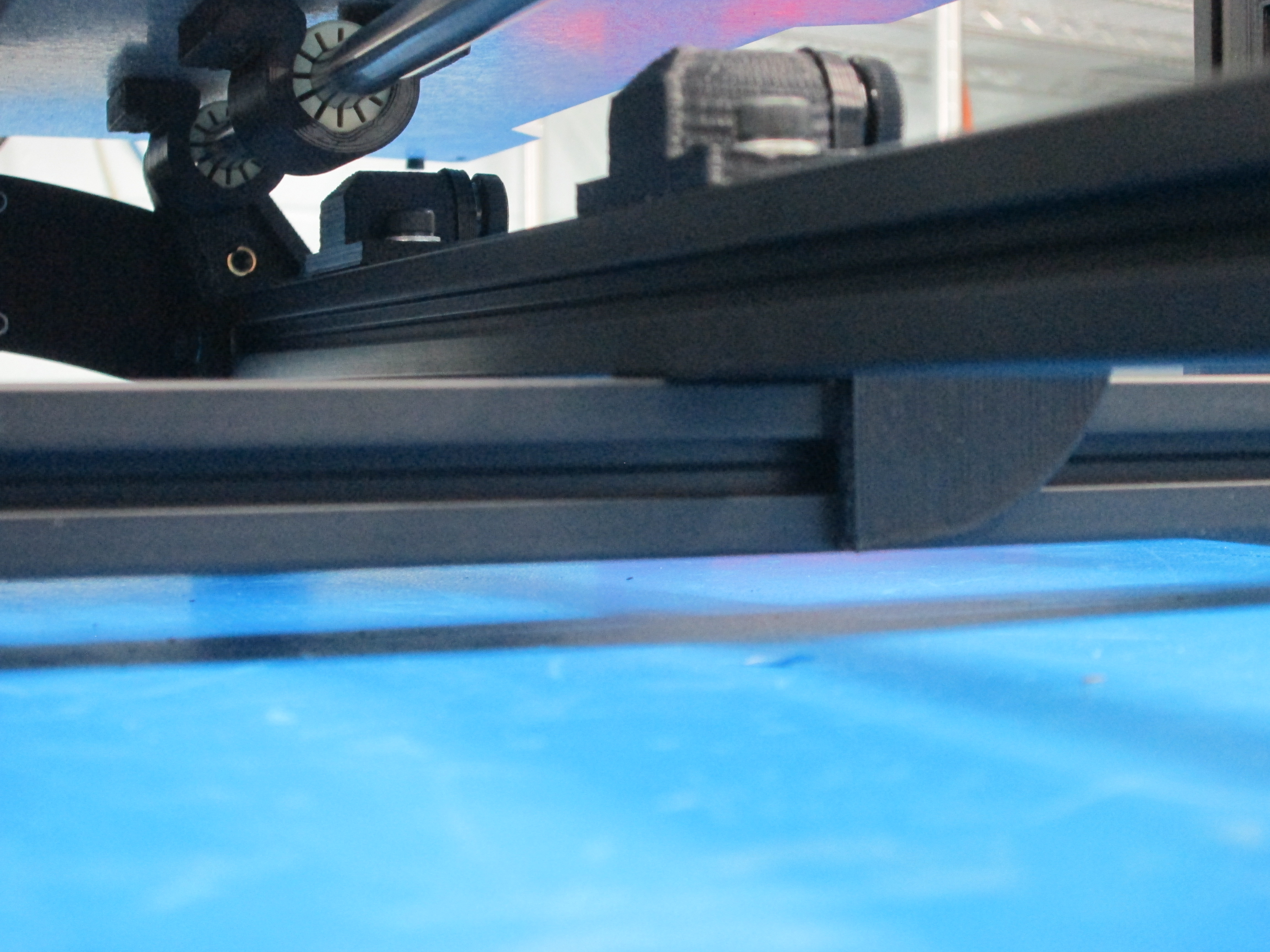
Make sure Y axis is sitting flush on frame with no gaps in between extrusions
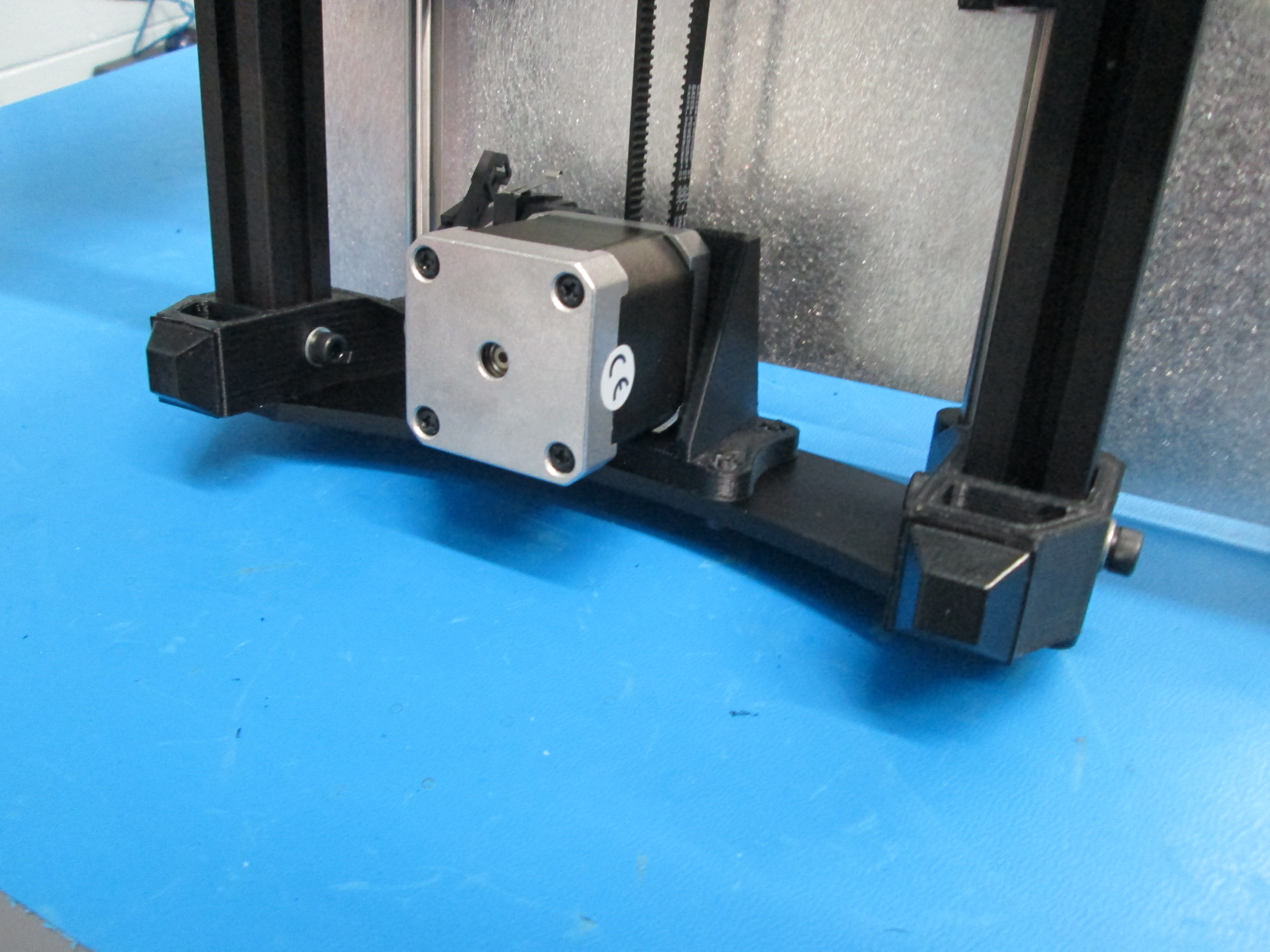
Route wires though relief #2.
Plug in as shown and put ground lug on post.
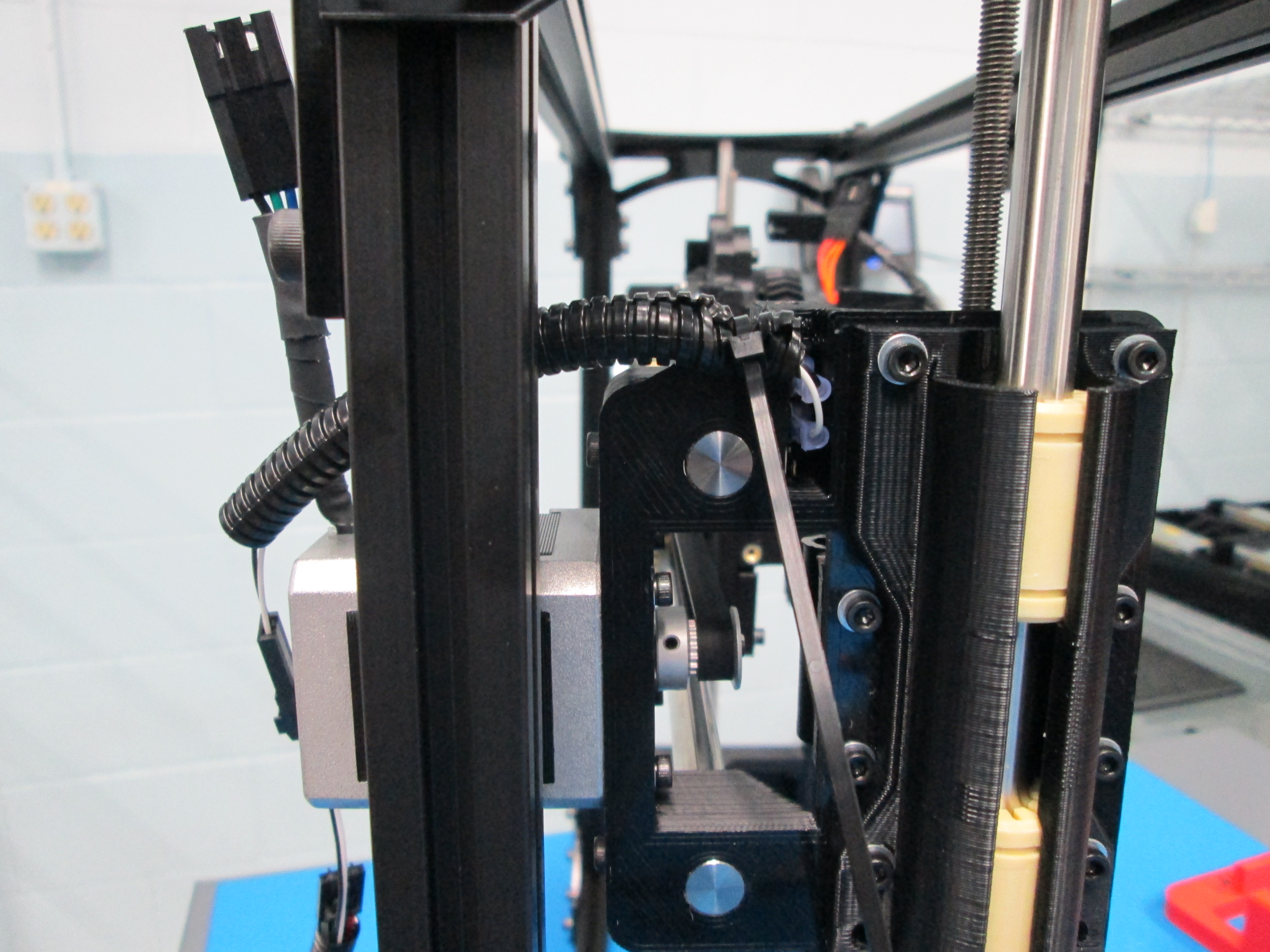
Plug in extensions to Y motor and Y switch.
Zip tie at 2 locations shown.
Install M3 nuts on ground posts.

Zip tie to Y plate as shown.
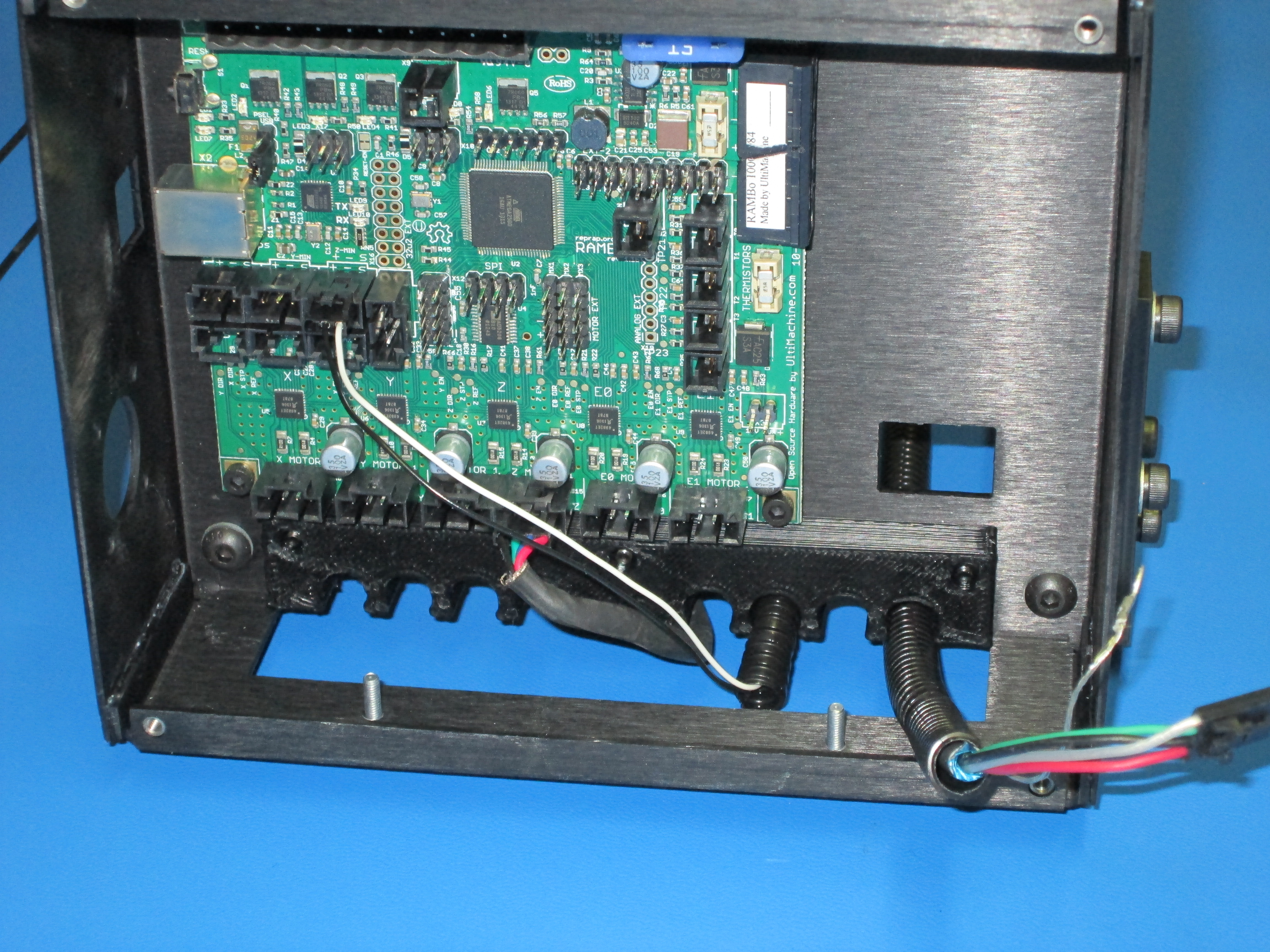
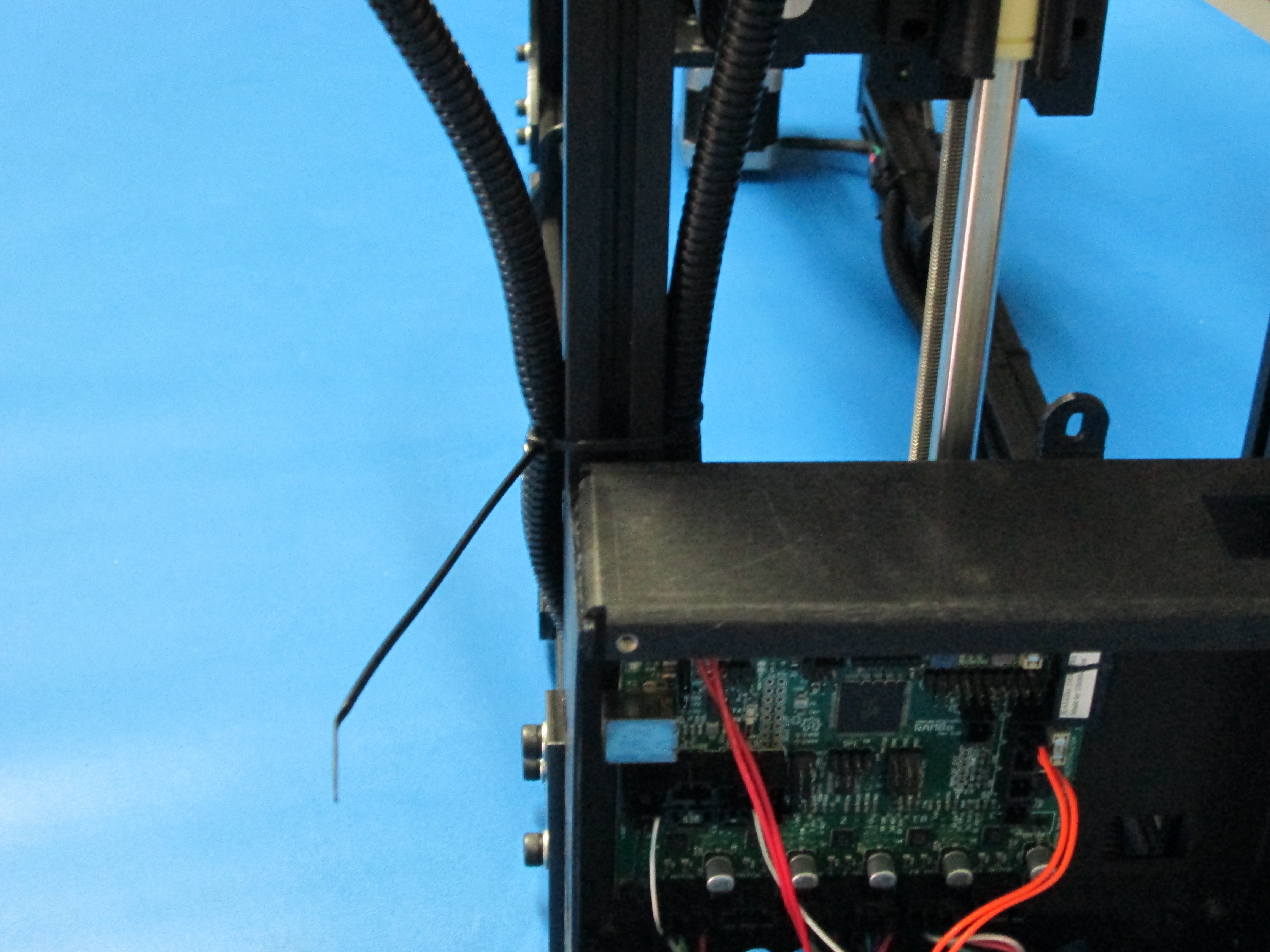
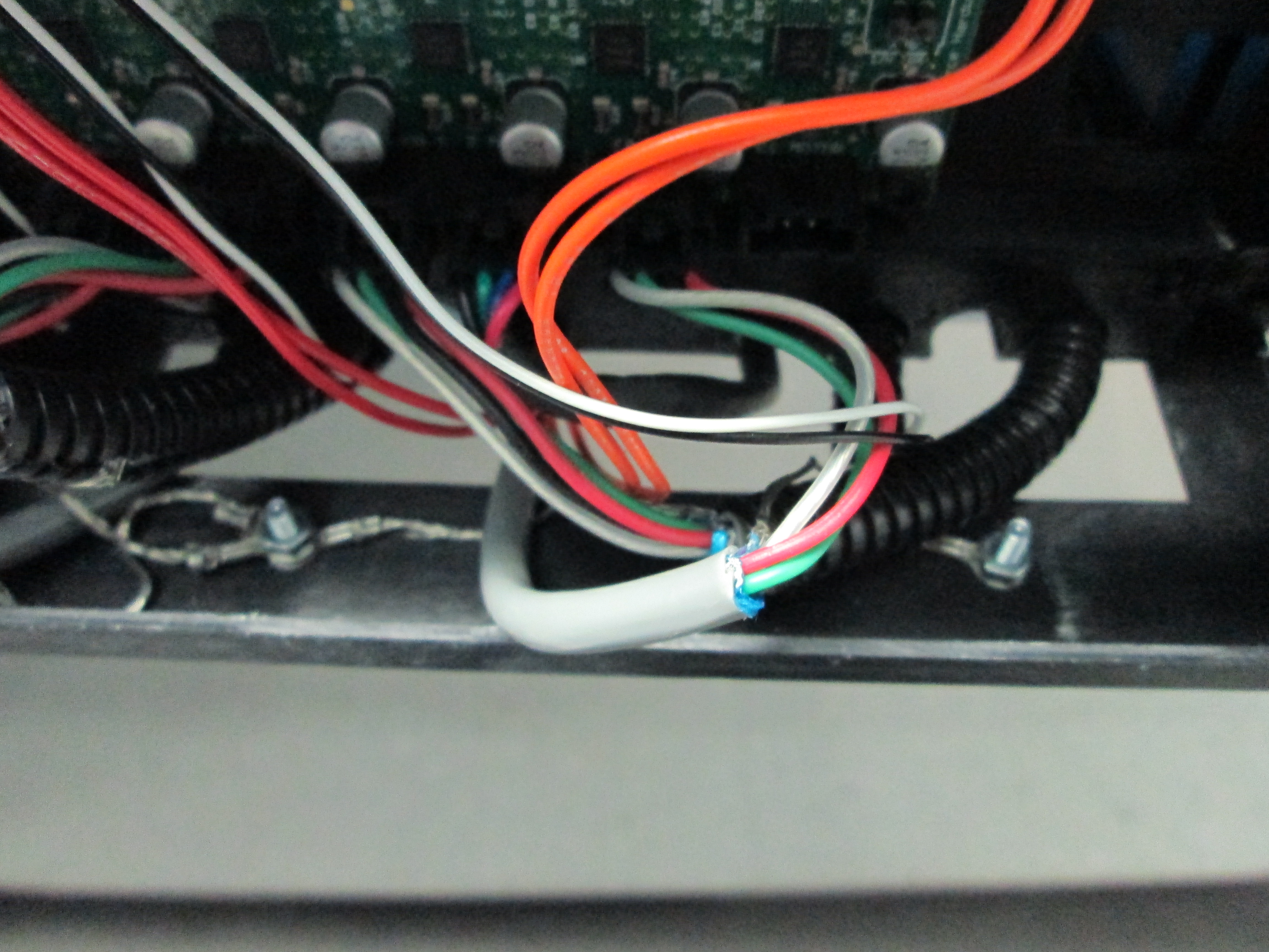
Route wires through frame connector and then through relief #3.
Plug in wires as shown.
Zip tie wires to frame connector as shown.


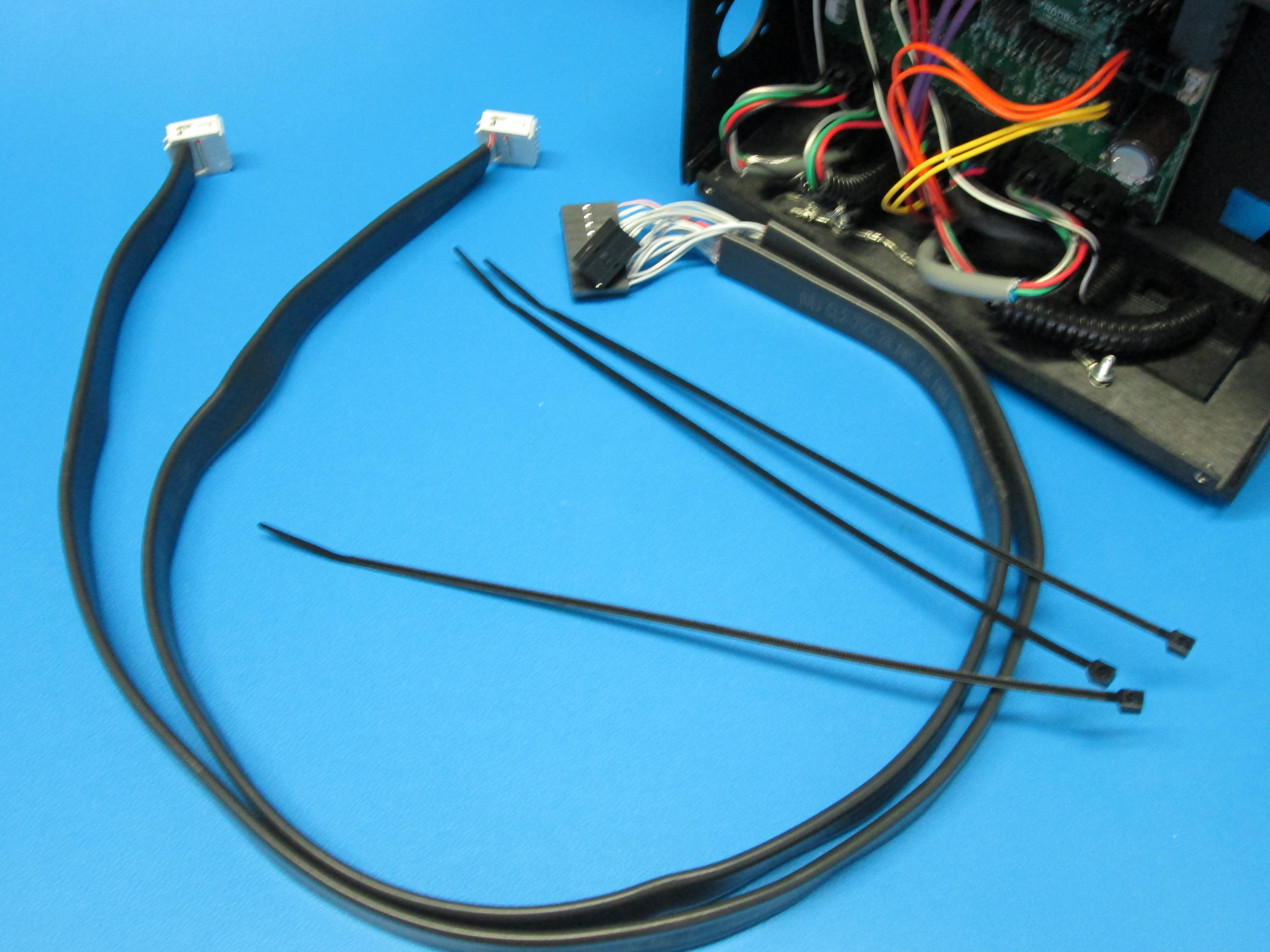
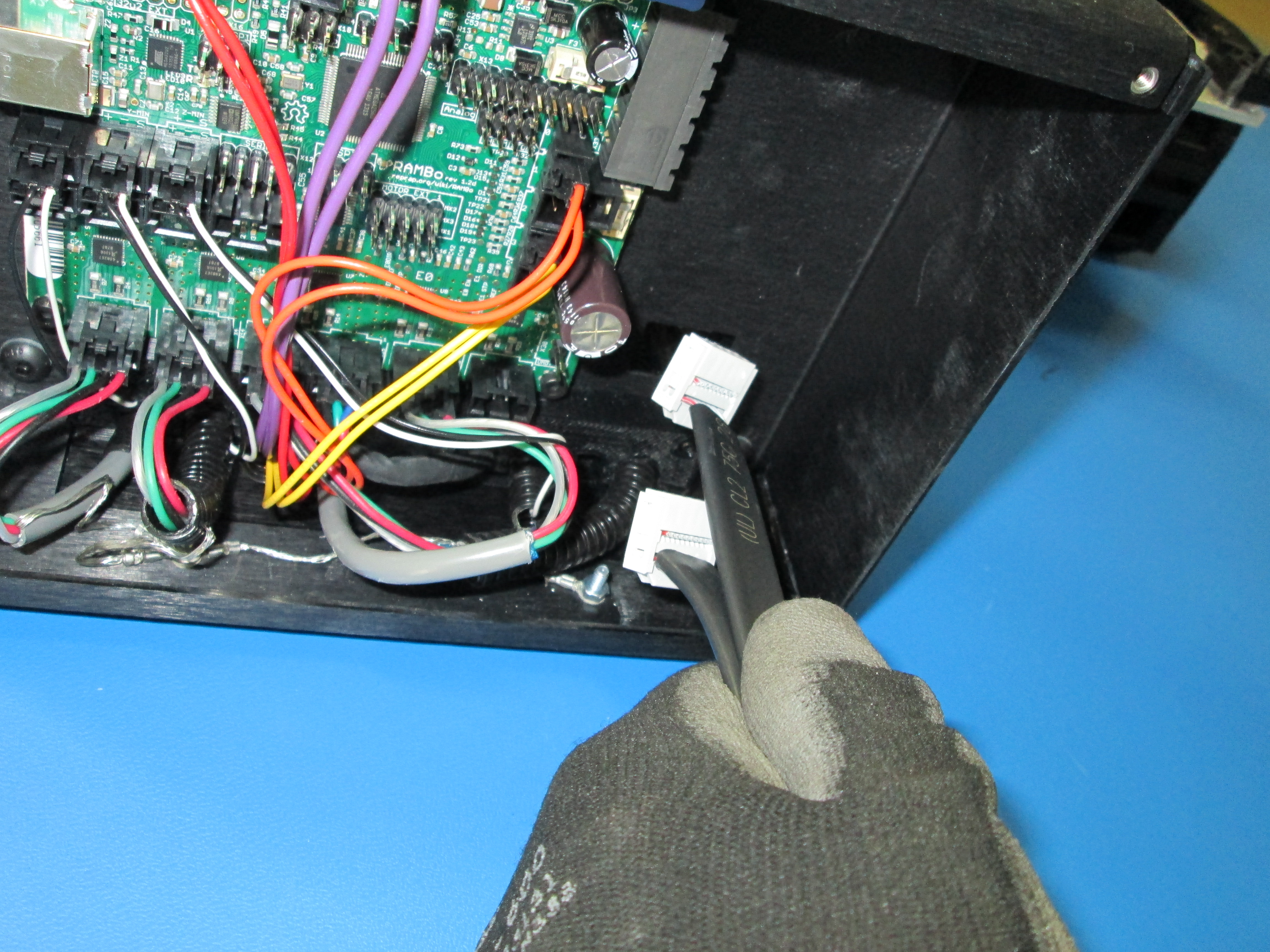
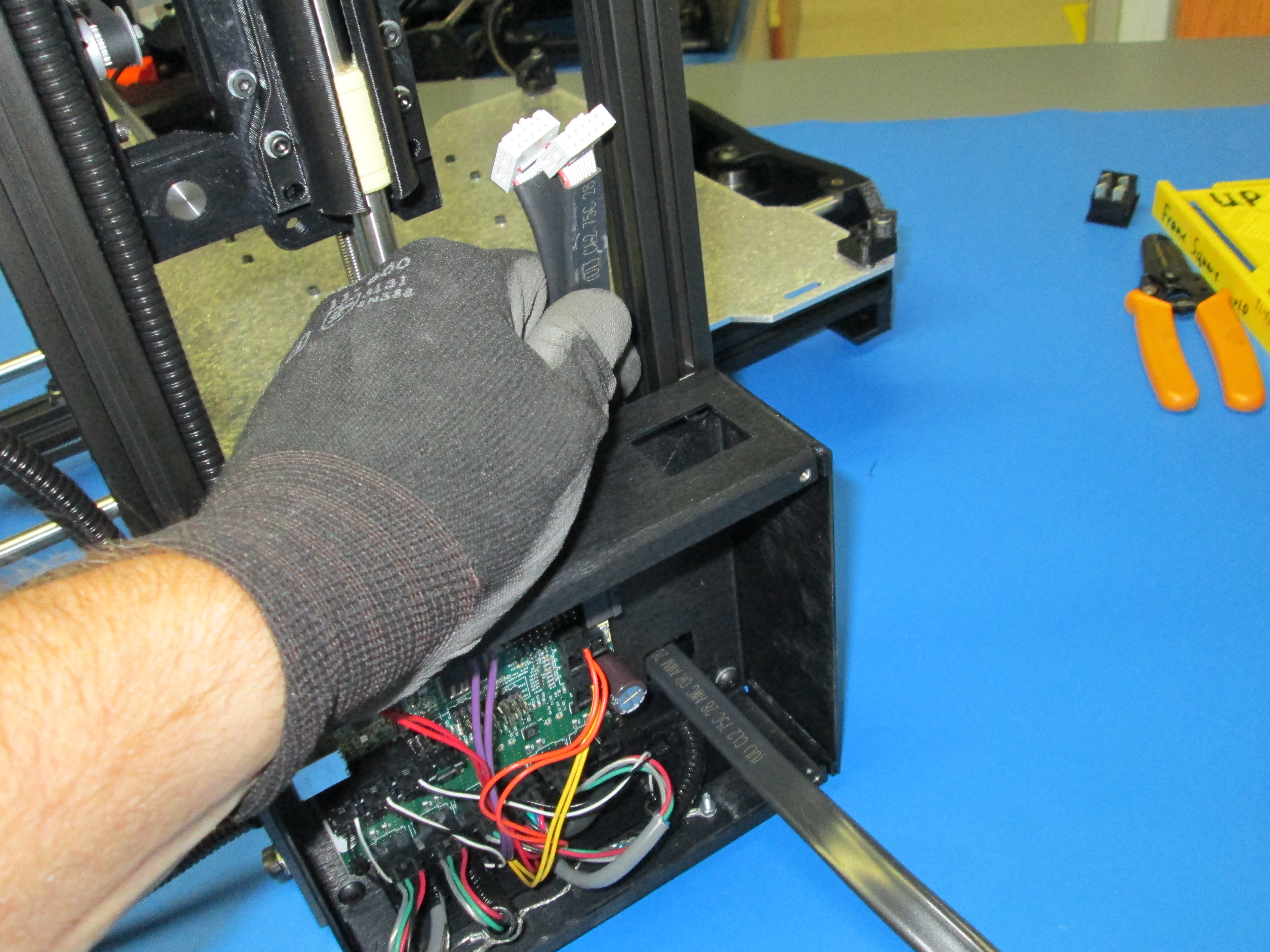
Note: The number 2 LCD wire connects to 2 plugs, the number 1 wire connects to just 1 plug.
With the number 2 LCD wire on top, feed both wires through the electronics case and around the back side of the closest extrusion.
Looking from the back of the printer, plug the number 2 wire into the furthest right plug on the back of the LCD. Plug the number 1 wire into the other plug.
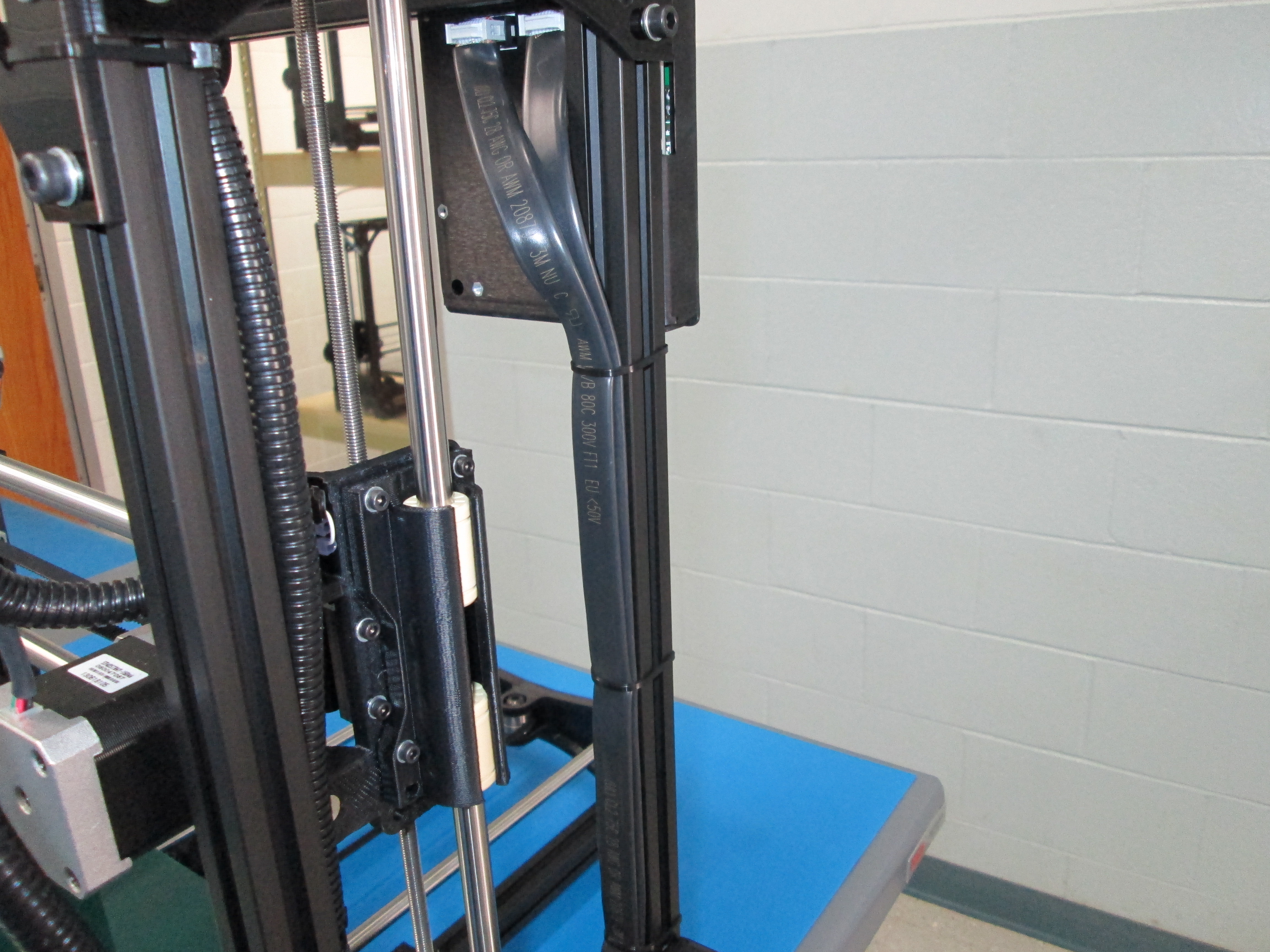
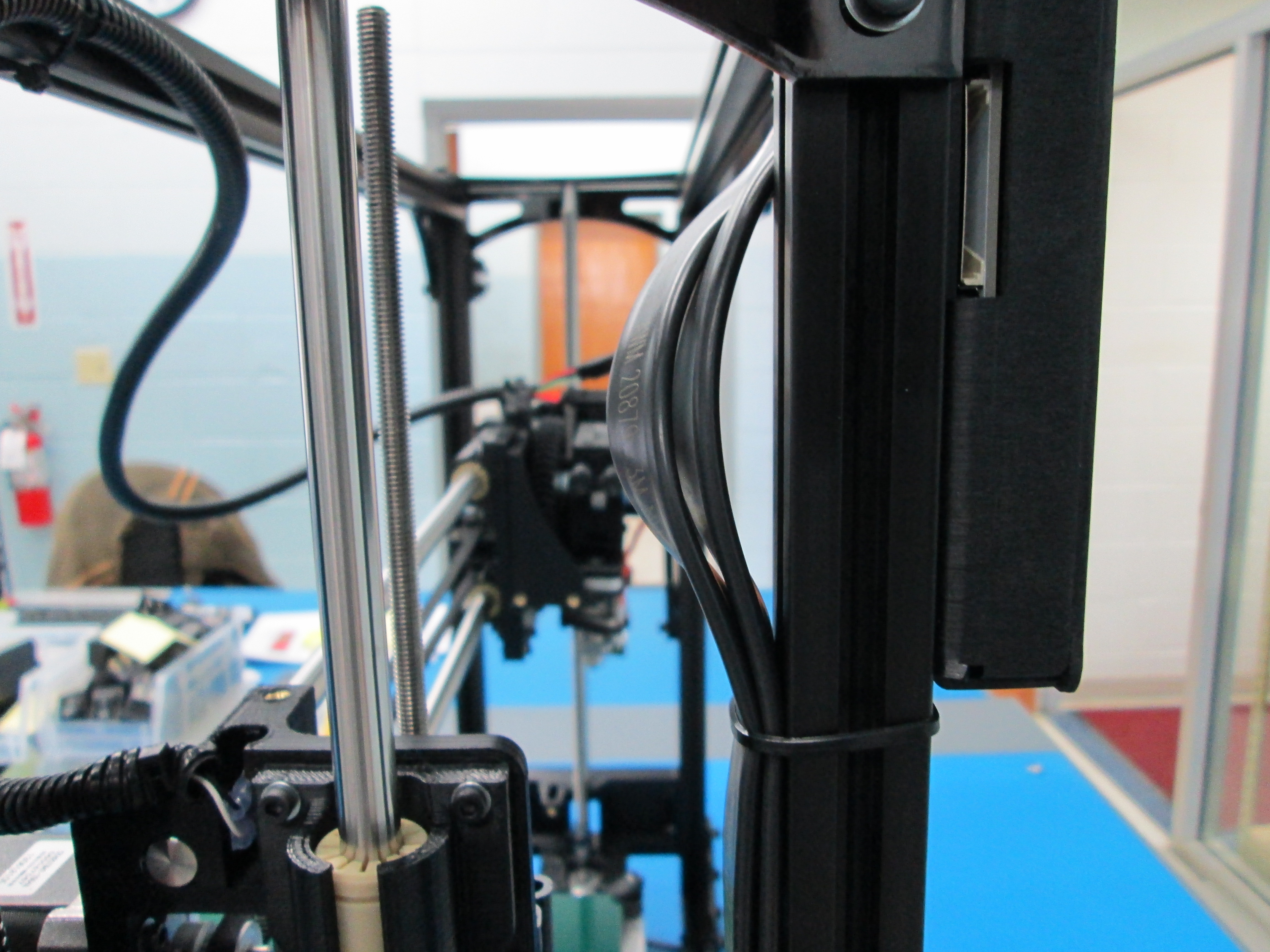
Keeping the wires as straight as possible, add 3 zip ties as shown. Leave some slack for the LCD plugs at top of wire.
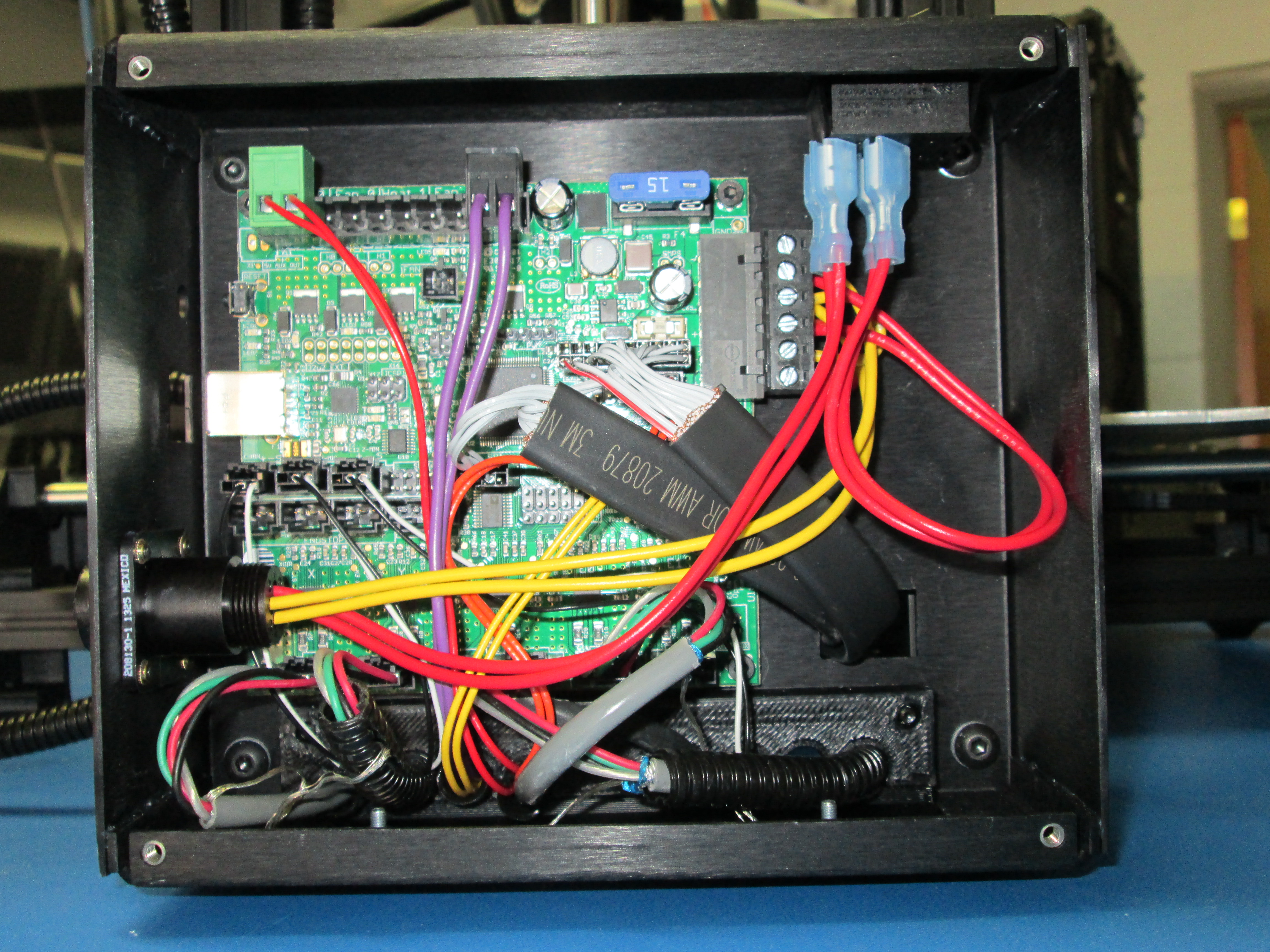
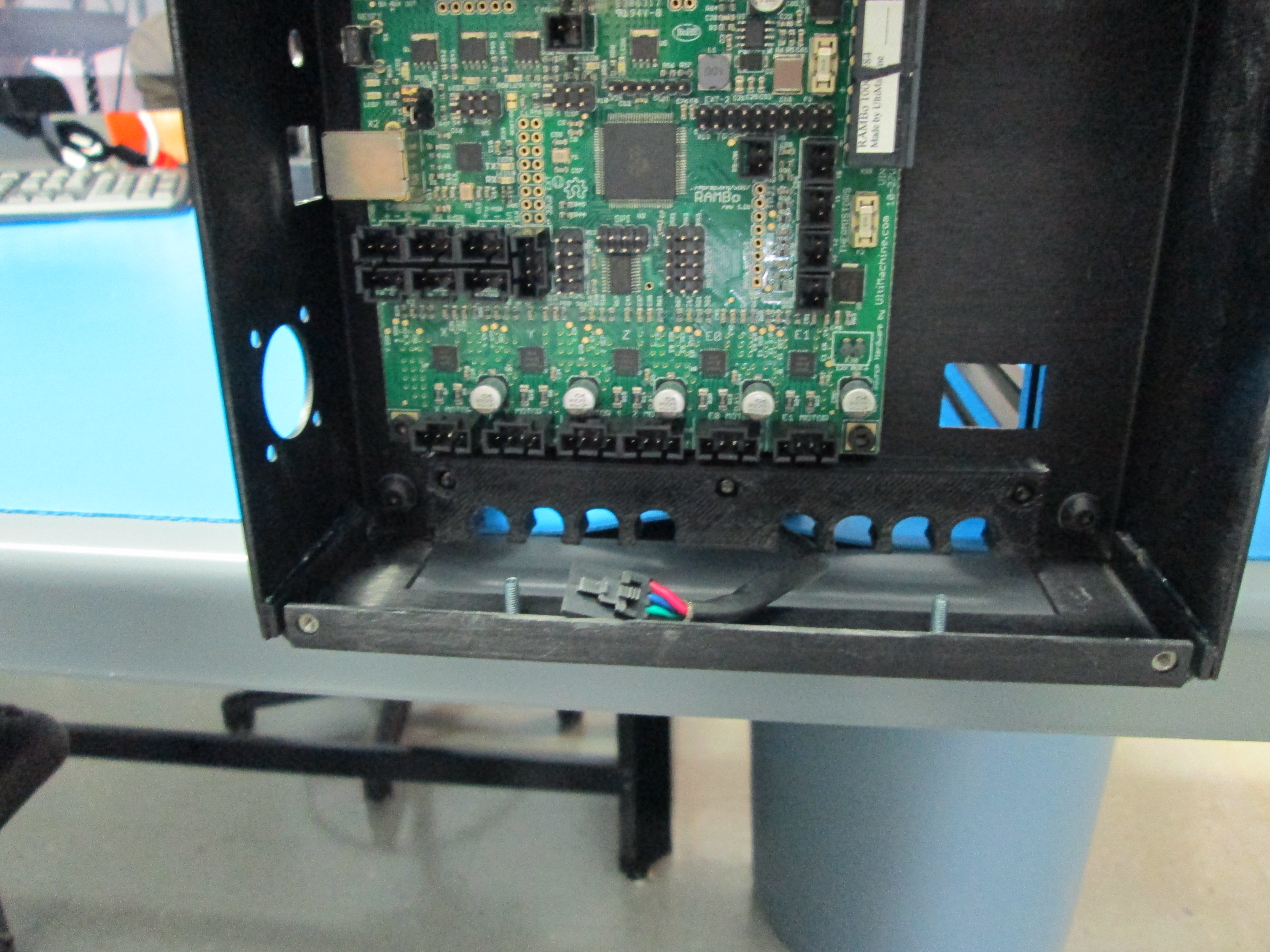
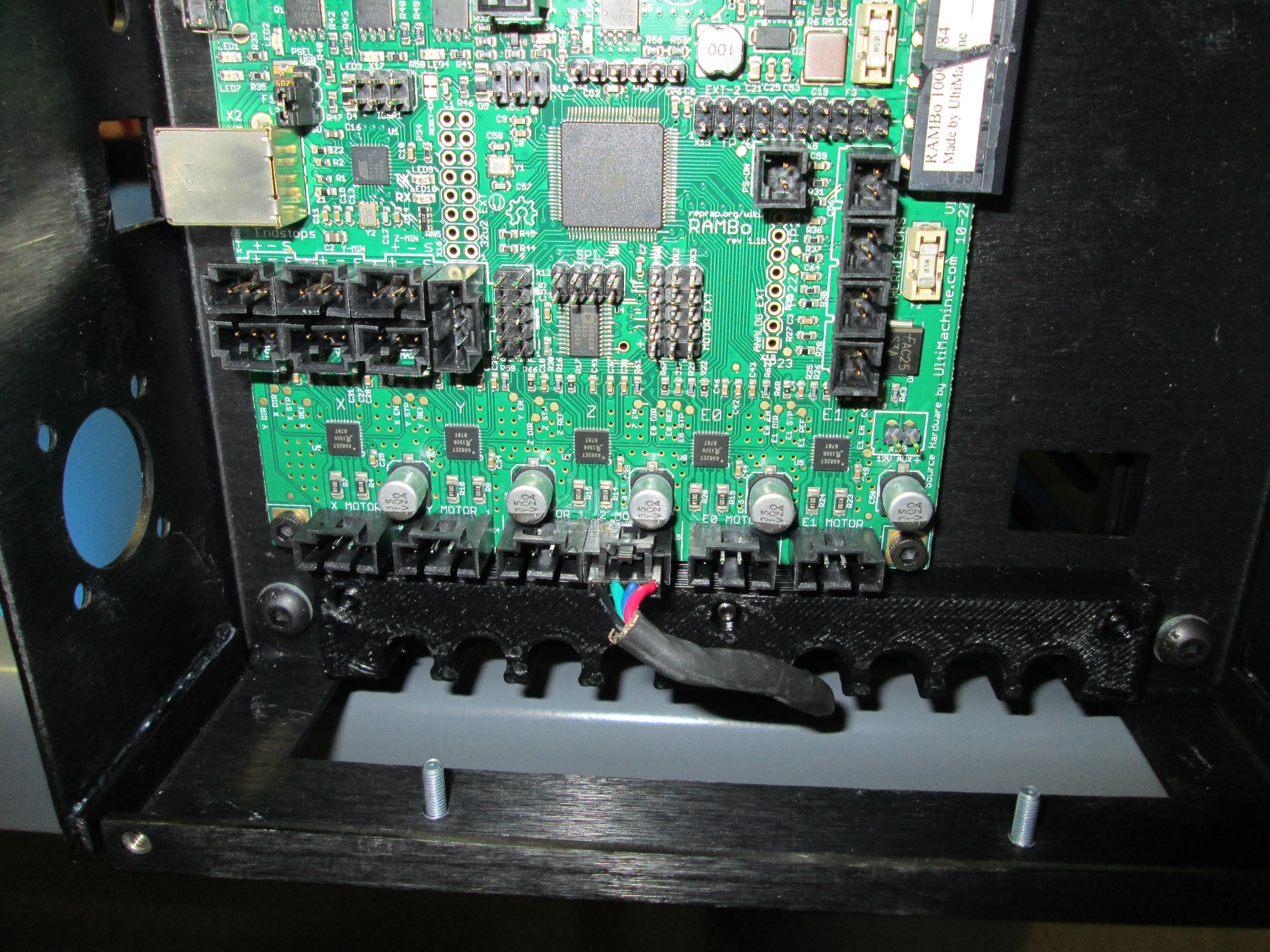
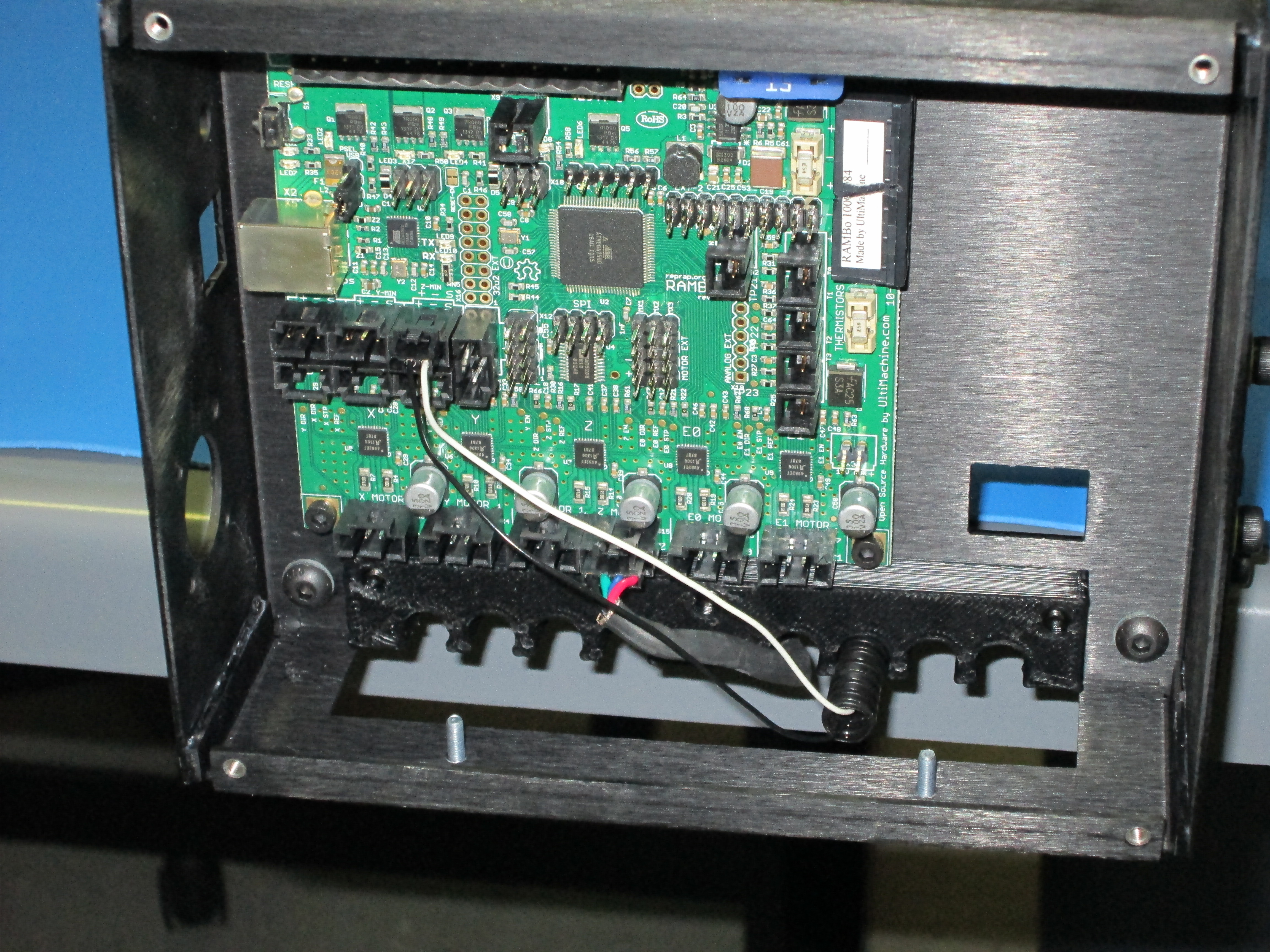
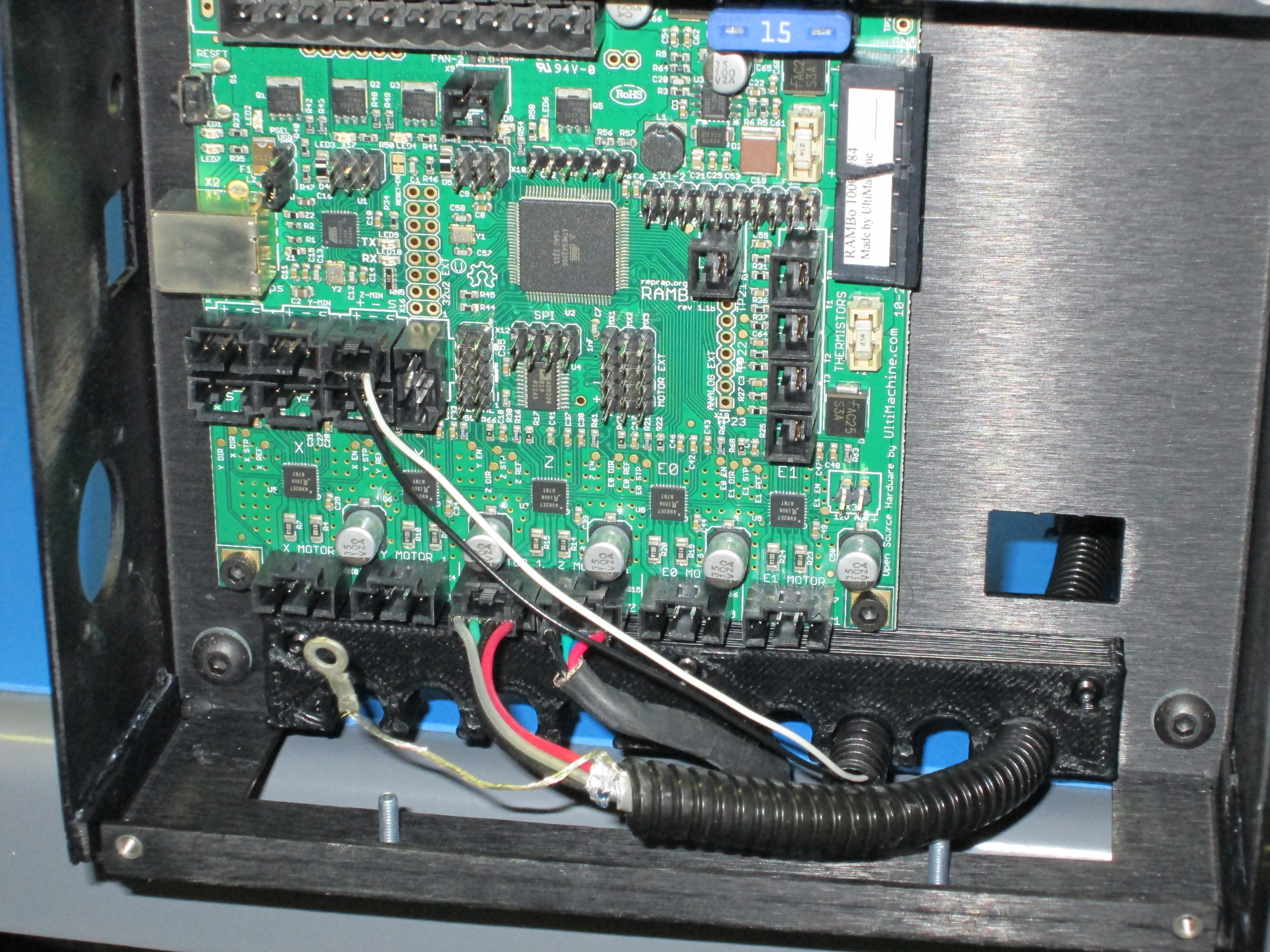
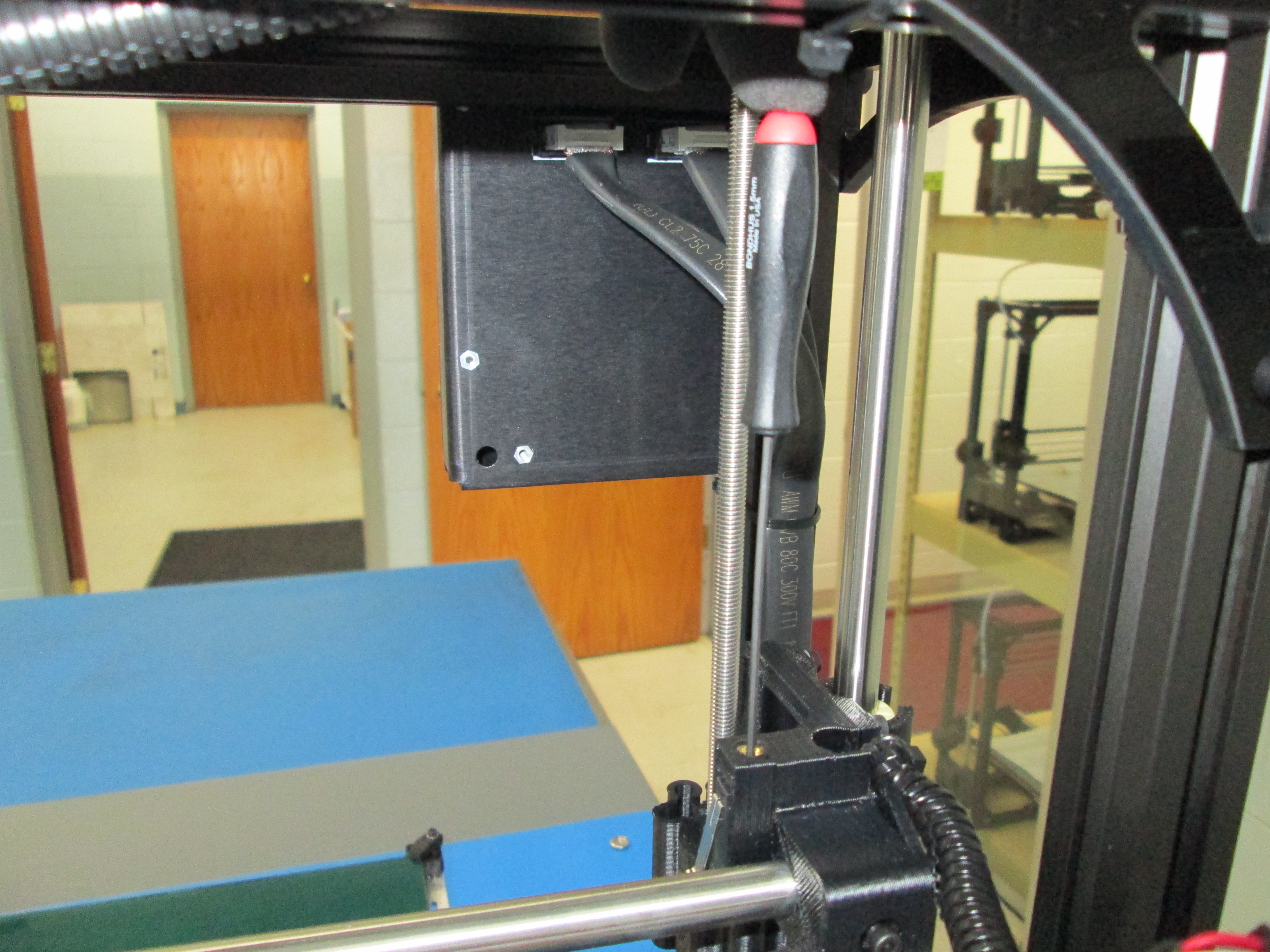
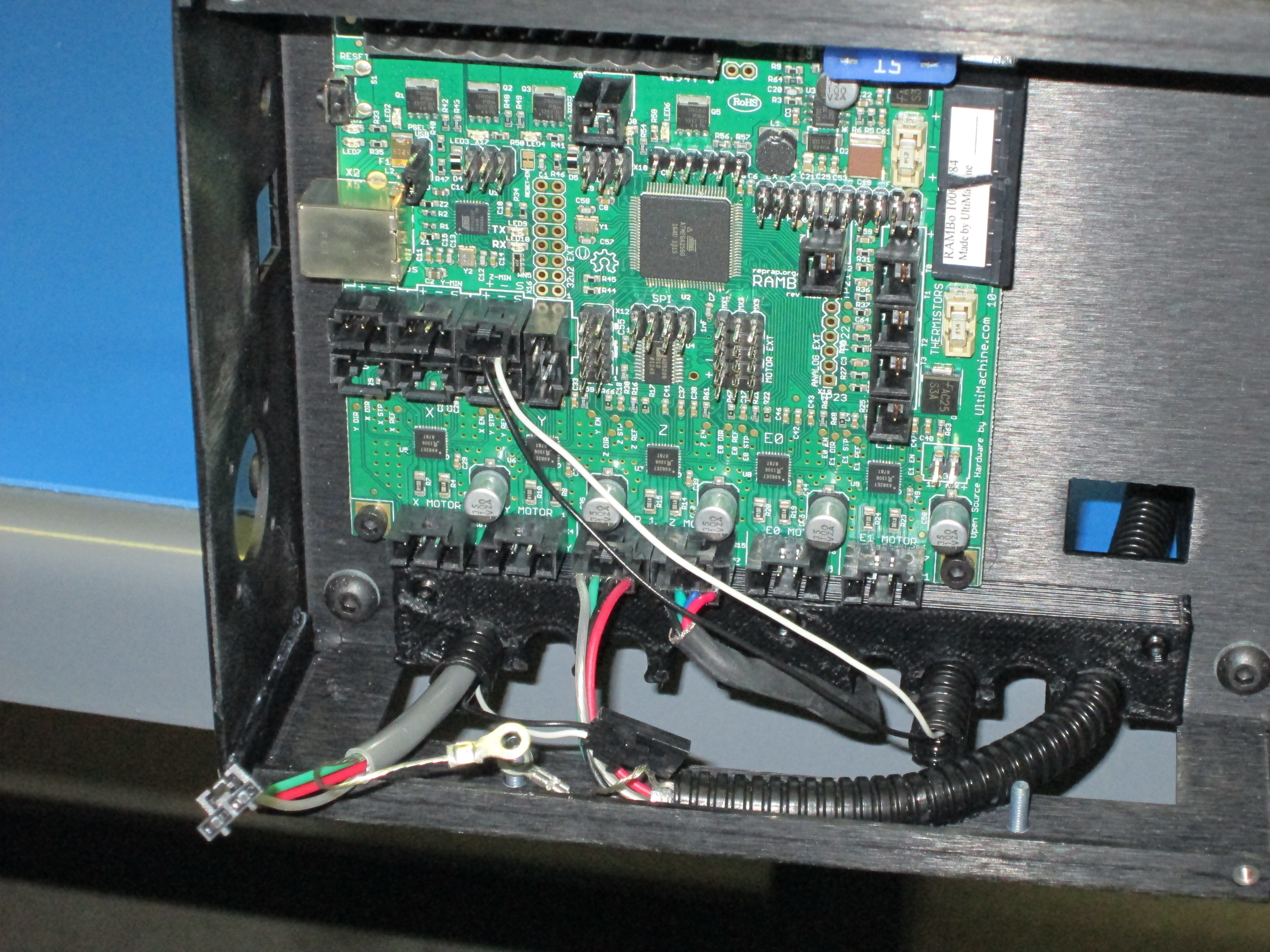
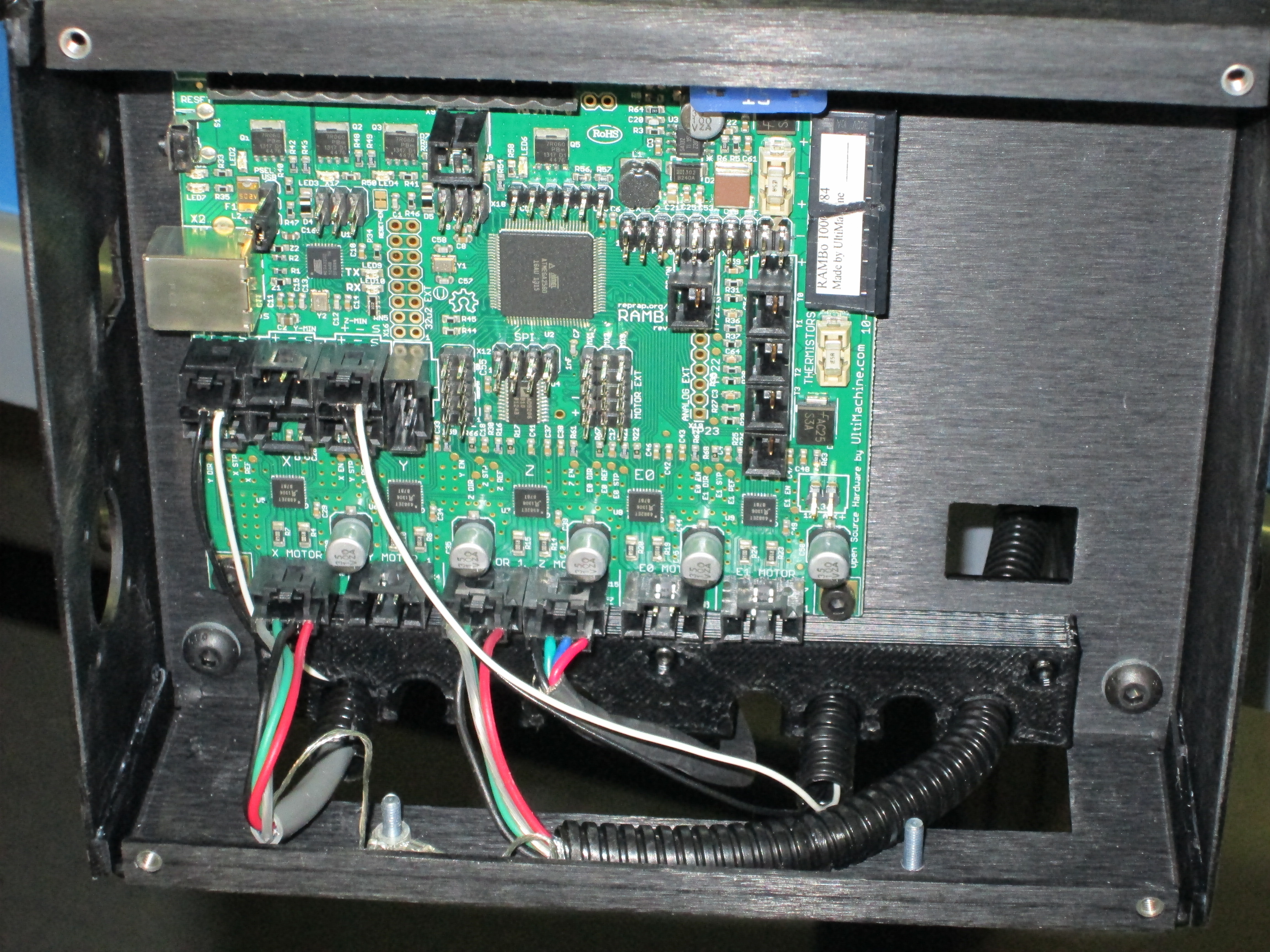
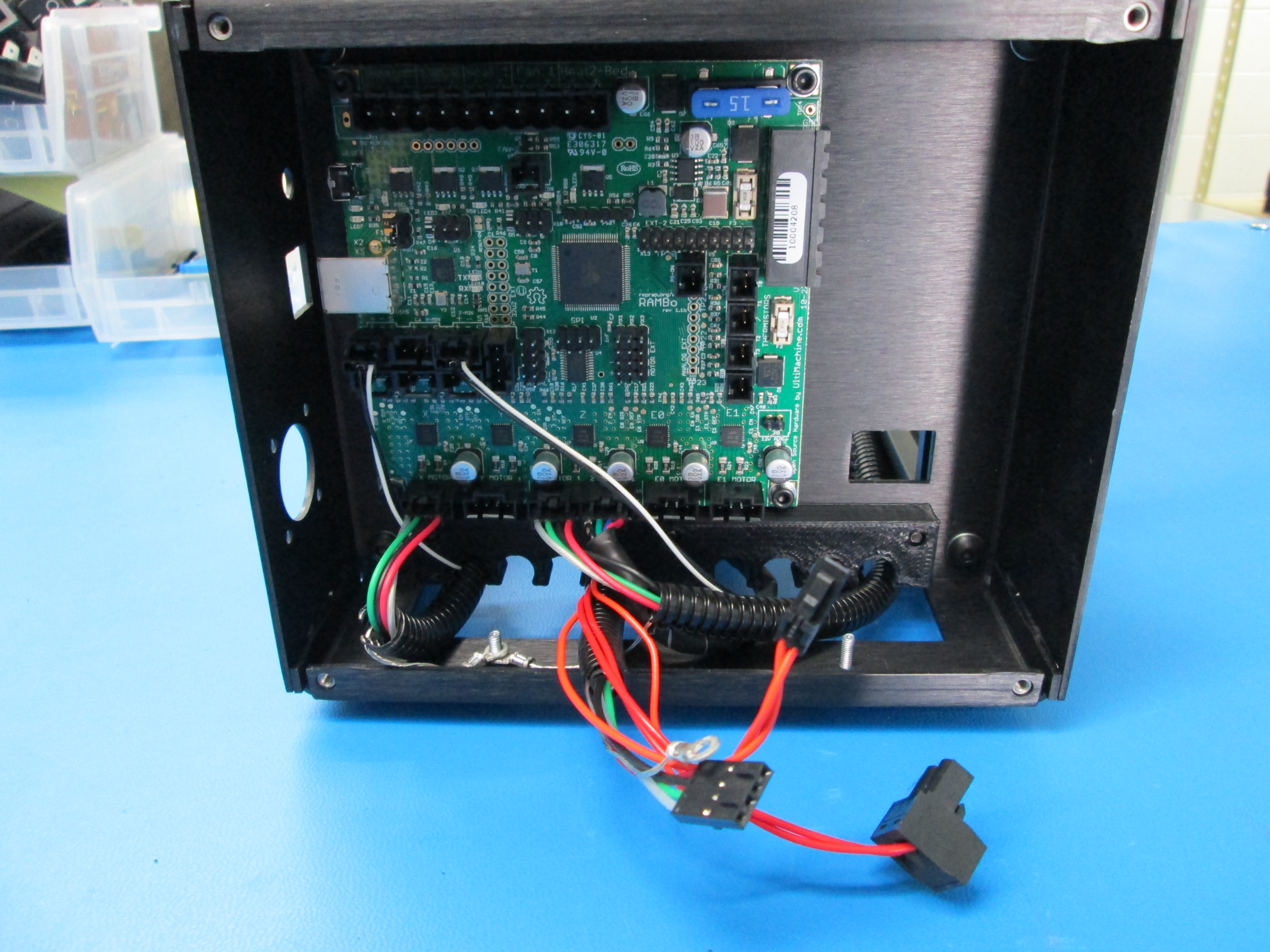
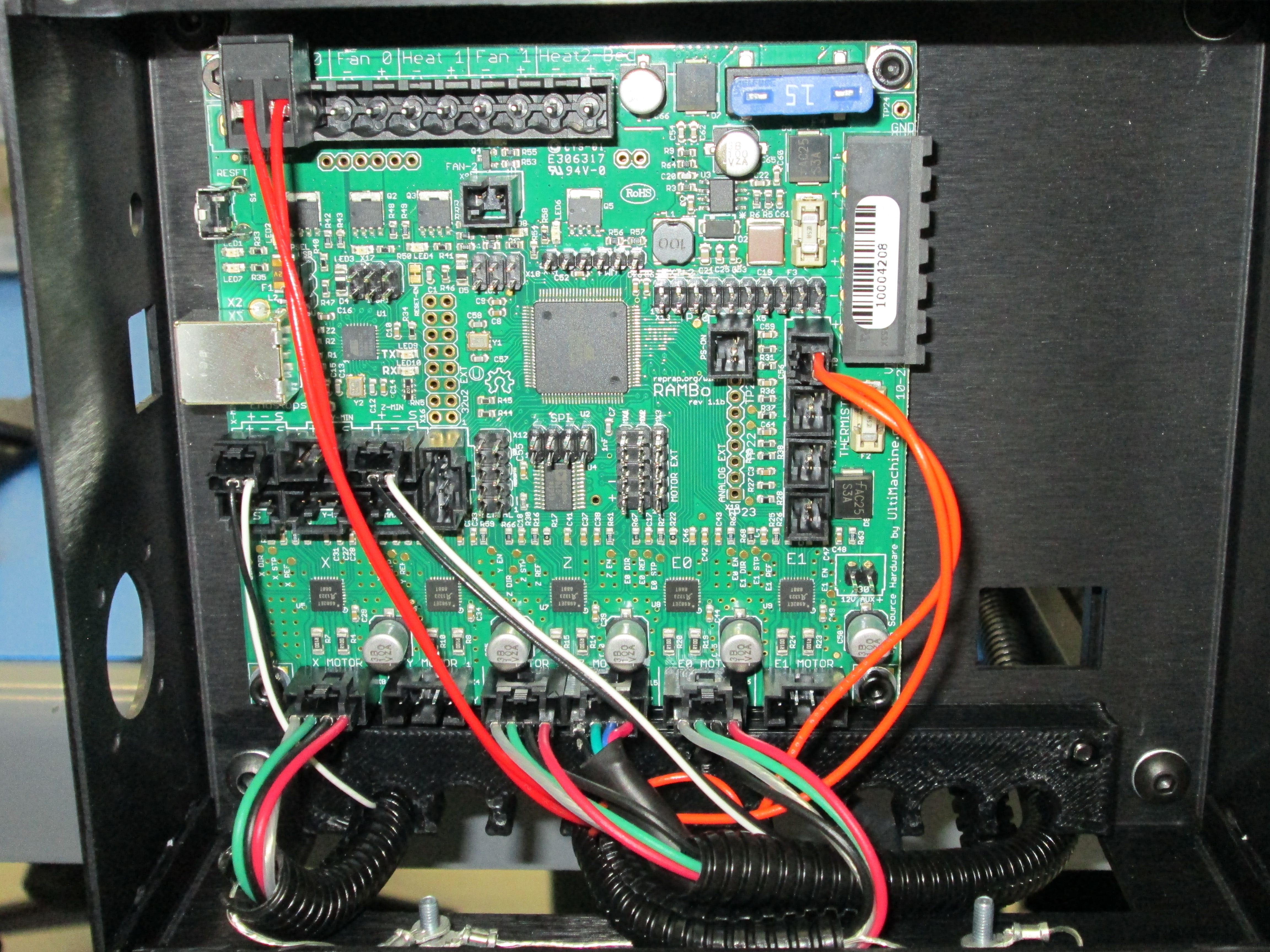
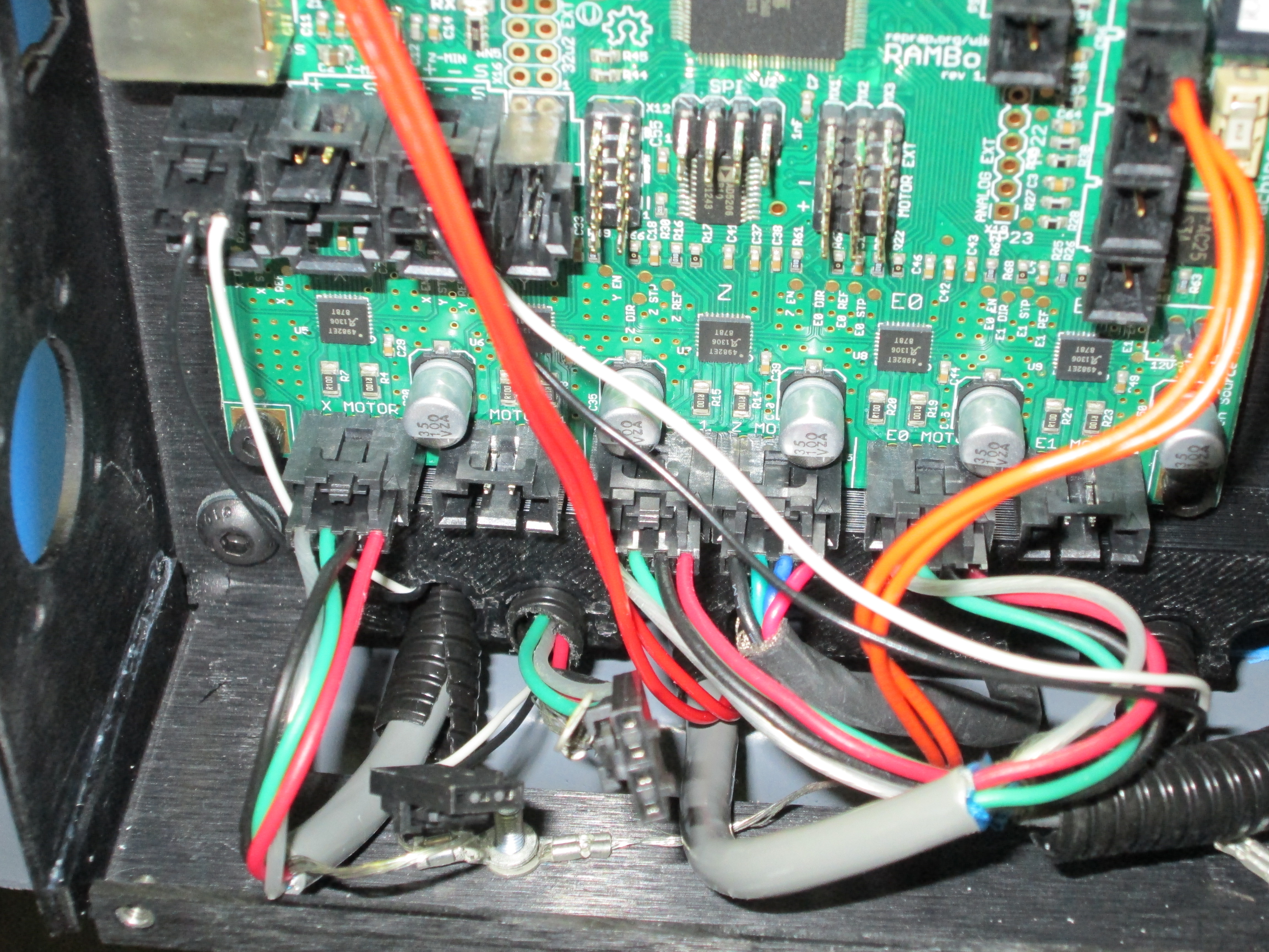
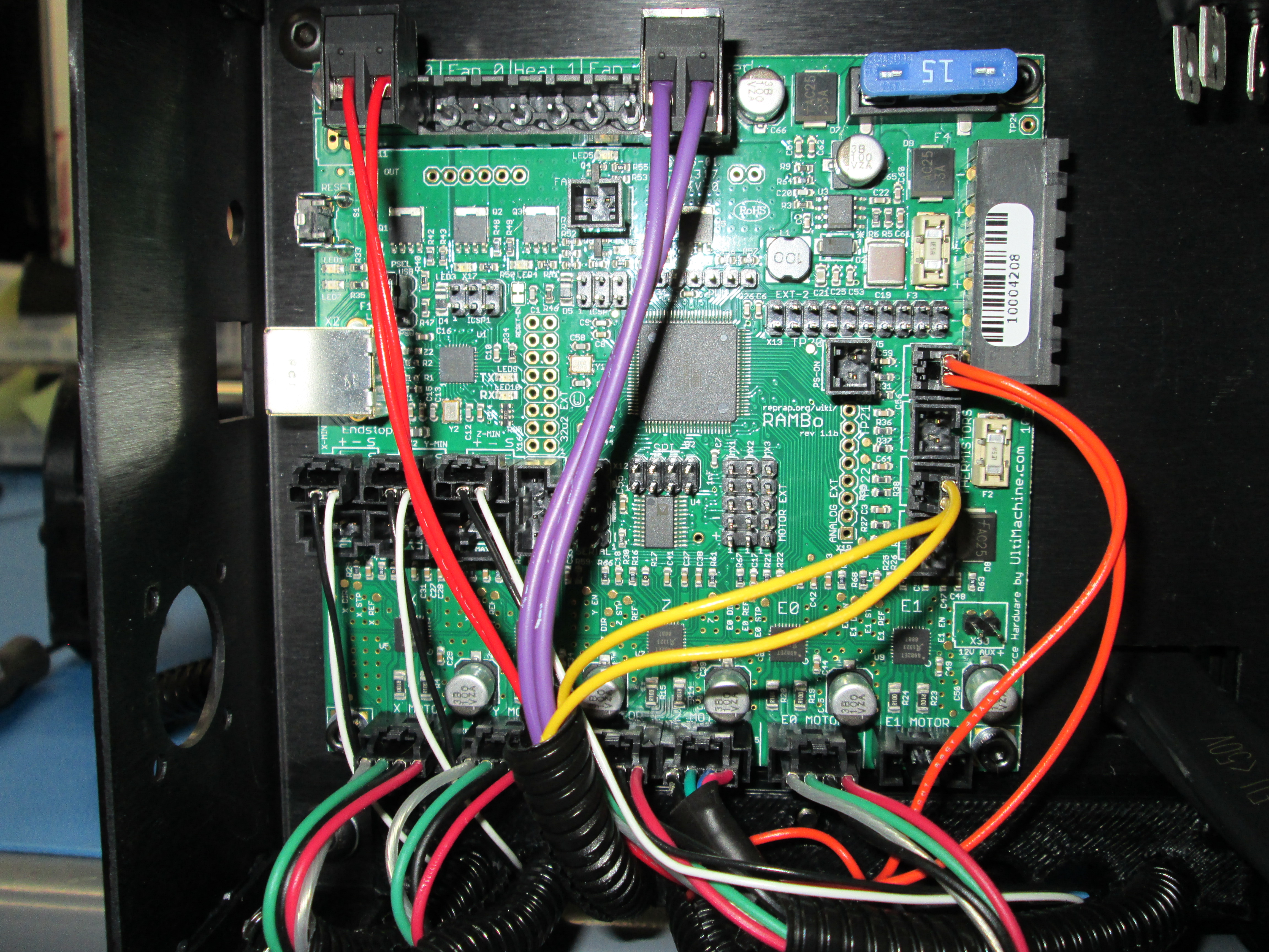
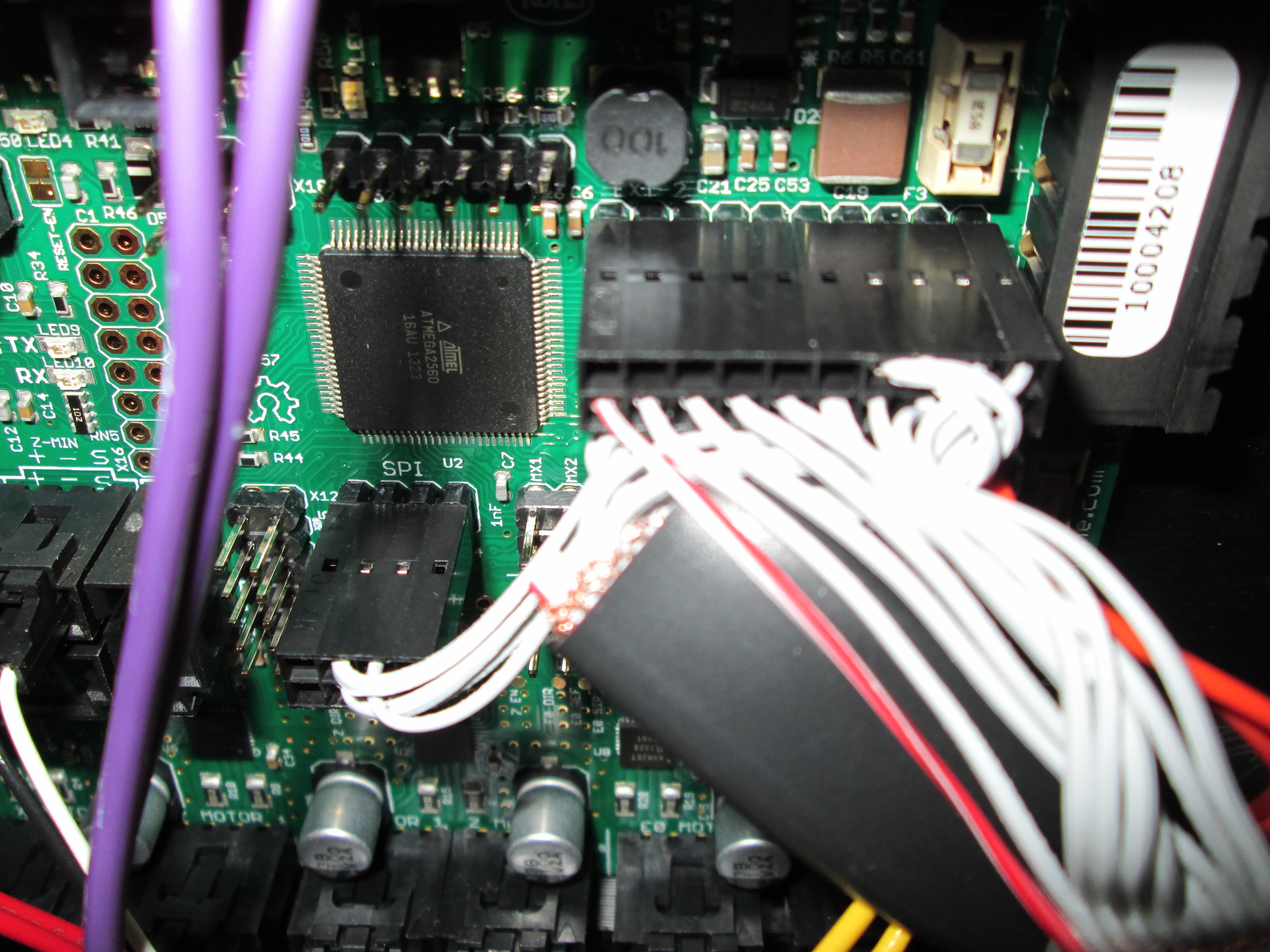
Connect the wires to the RAMBo in the positions shown. Note: The arrow on each plug indicates the upper left hand pin position.
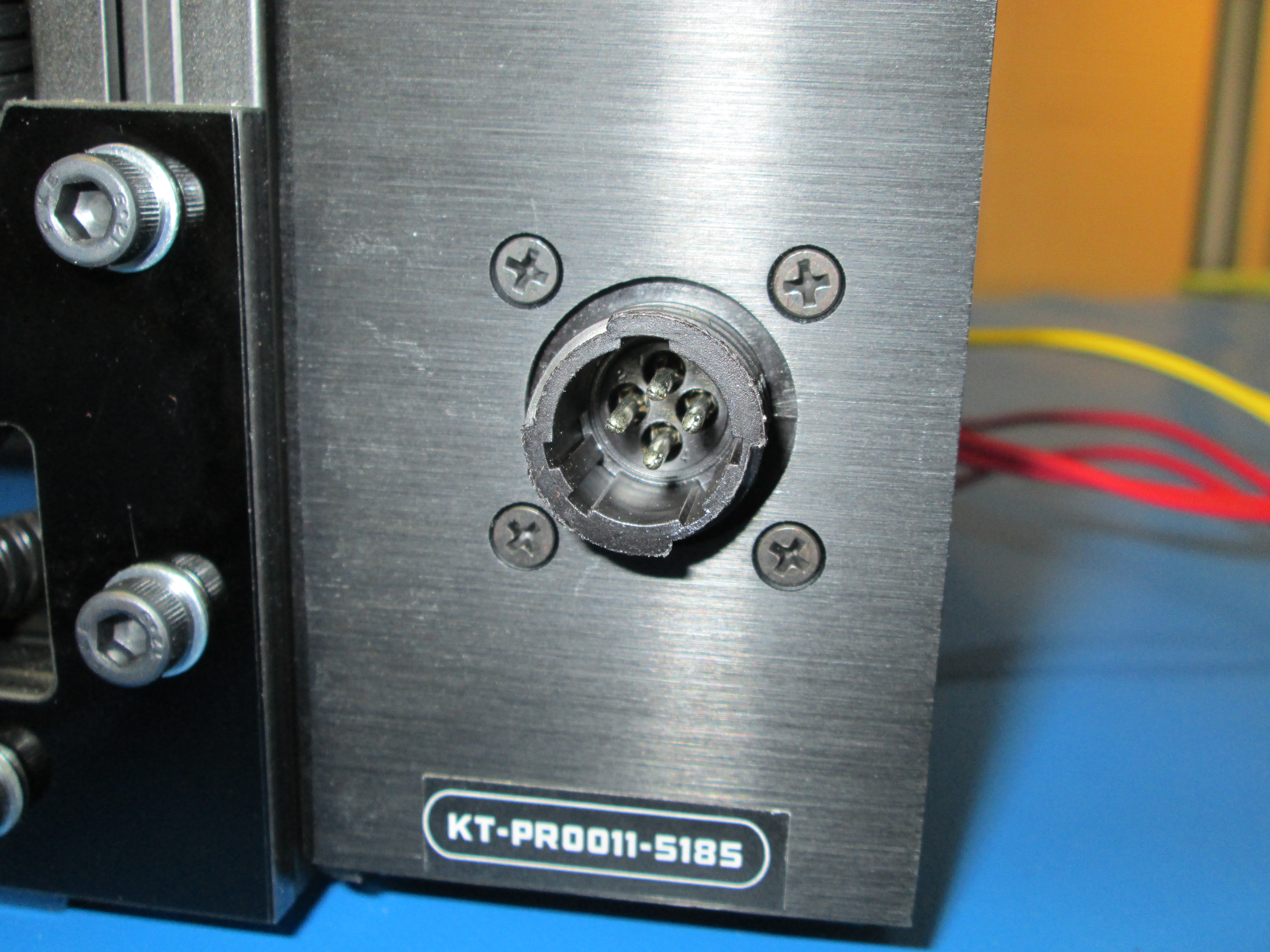
Install the power plug into the electronics case using 4 4-40 x .25 Flat head screws. The single large key slot in the plug should be towards the top of the printer.
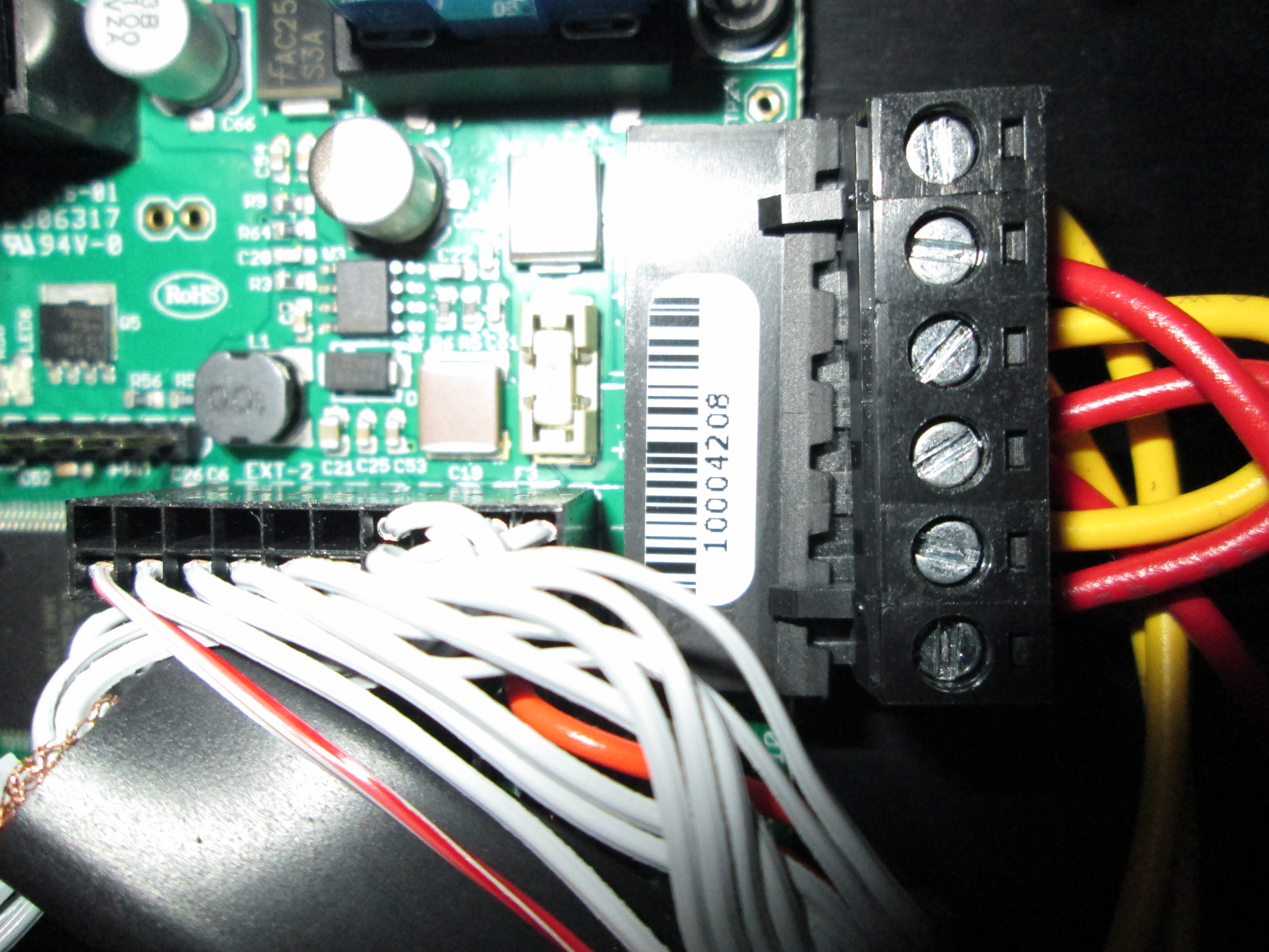
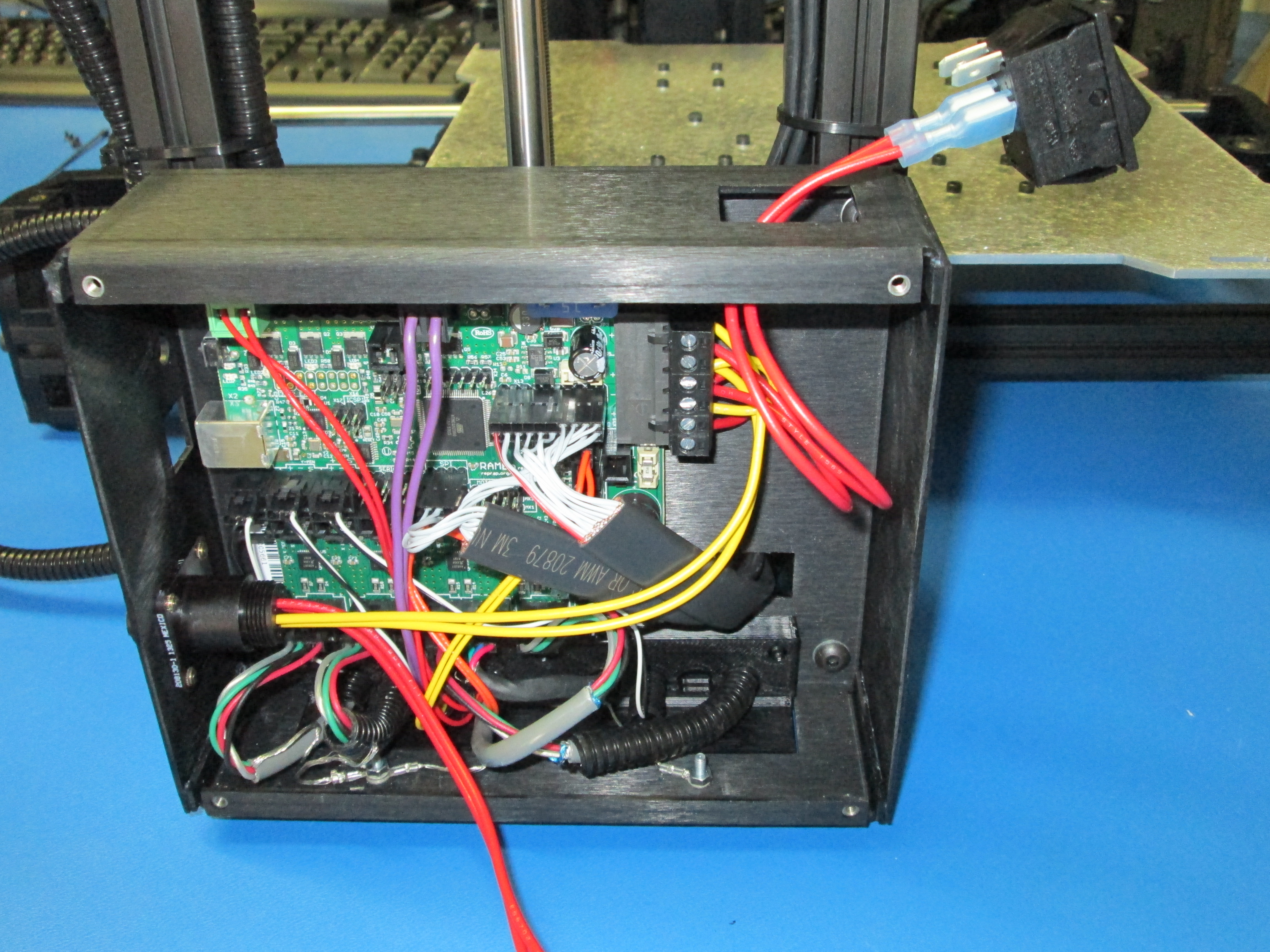
Insert the 6 pin power connector into the plug on the top right of the RAMBo board.
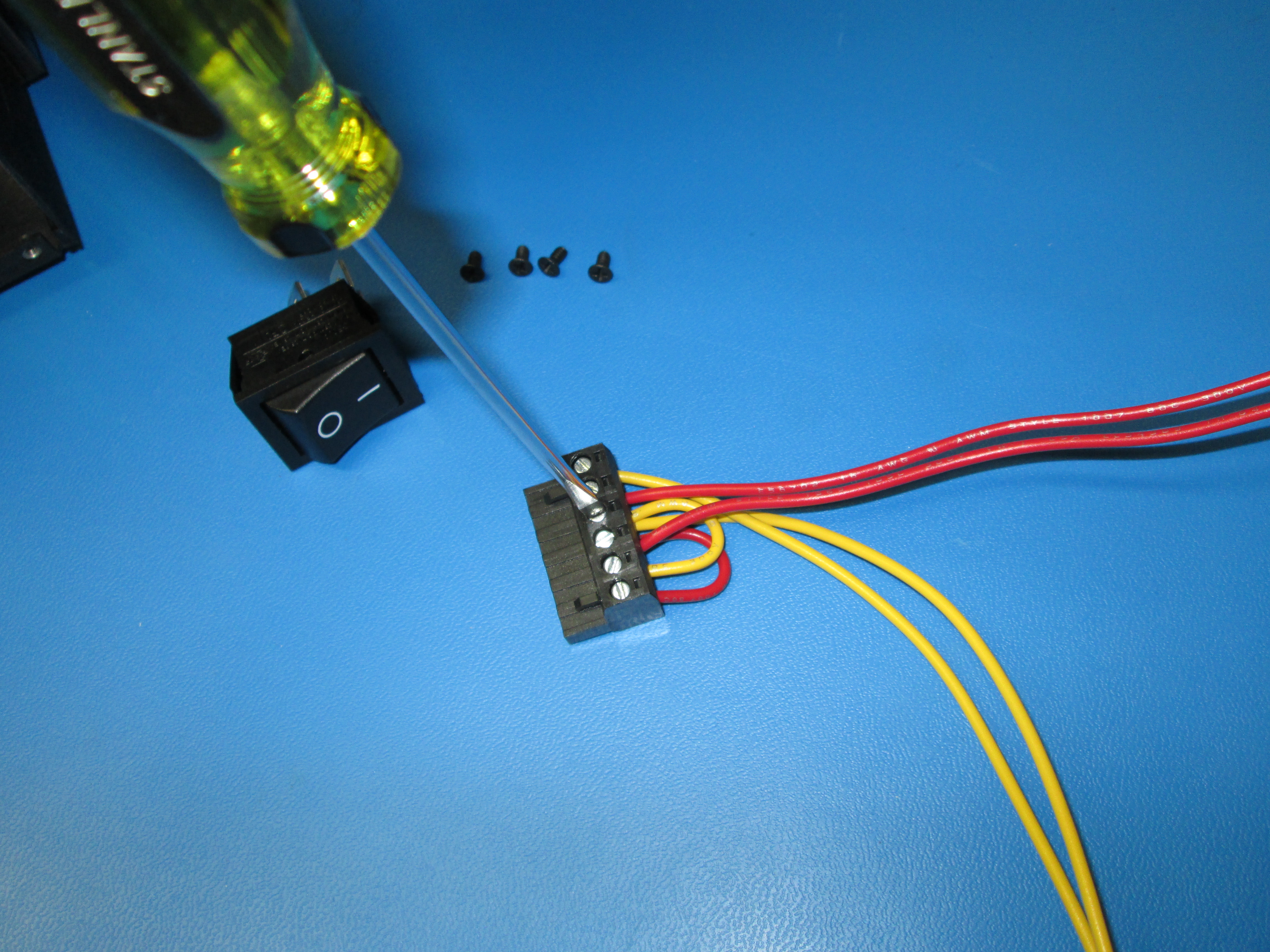
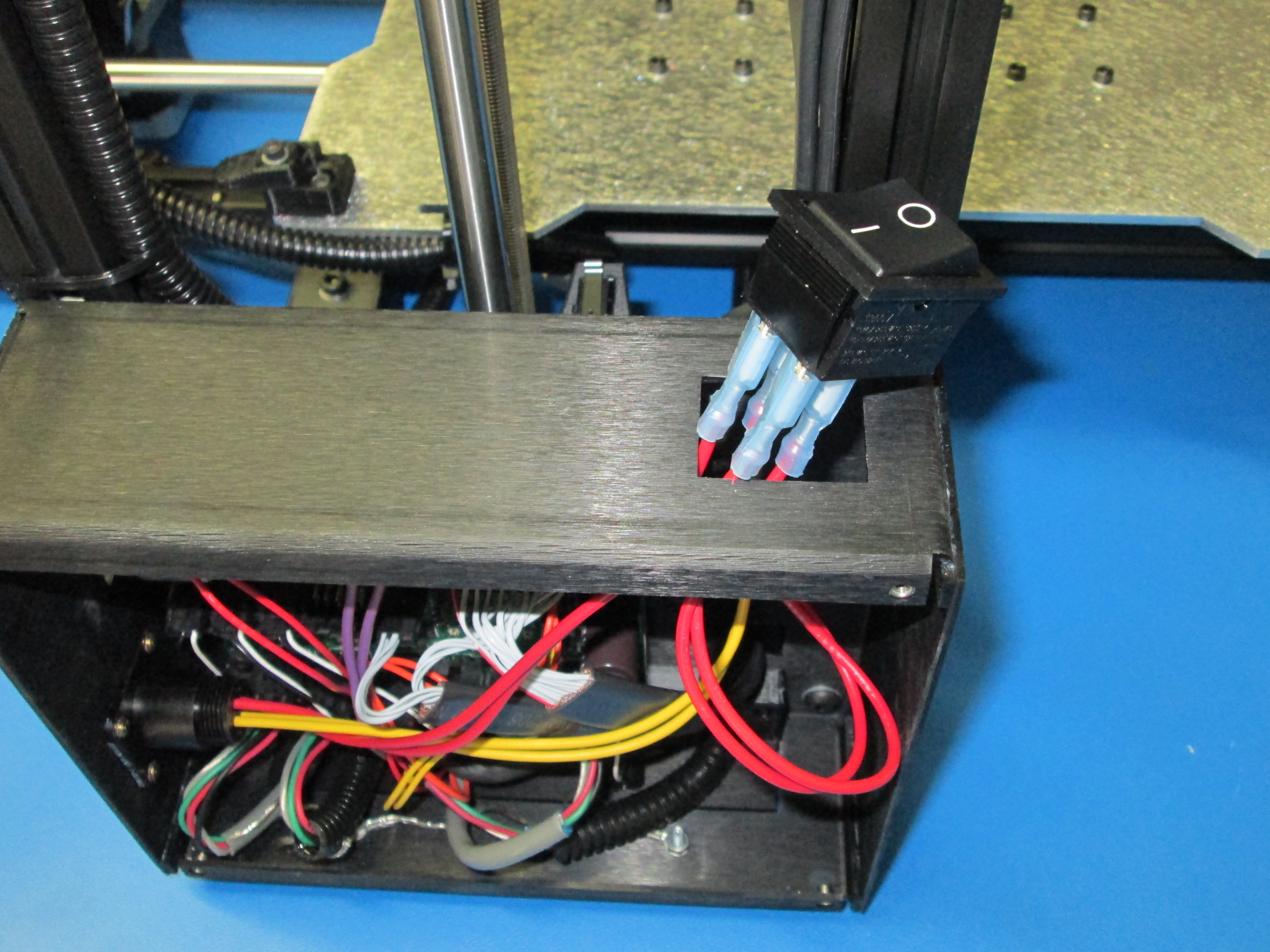
Run the power wires from the 6 pin connector through the square hole in the top of the electronics case. Connect the two wires to the 'OFF' side of the power switch.
Run the wires from the power plug through the square hole and connect them to the 'ON' side of the power switch.
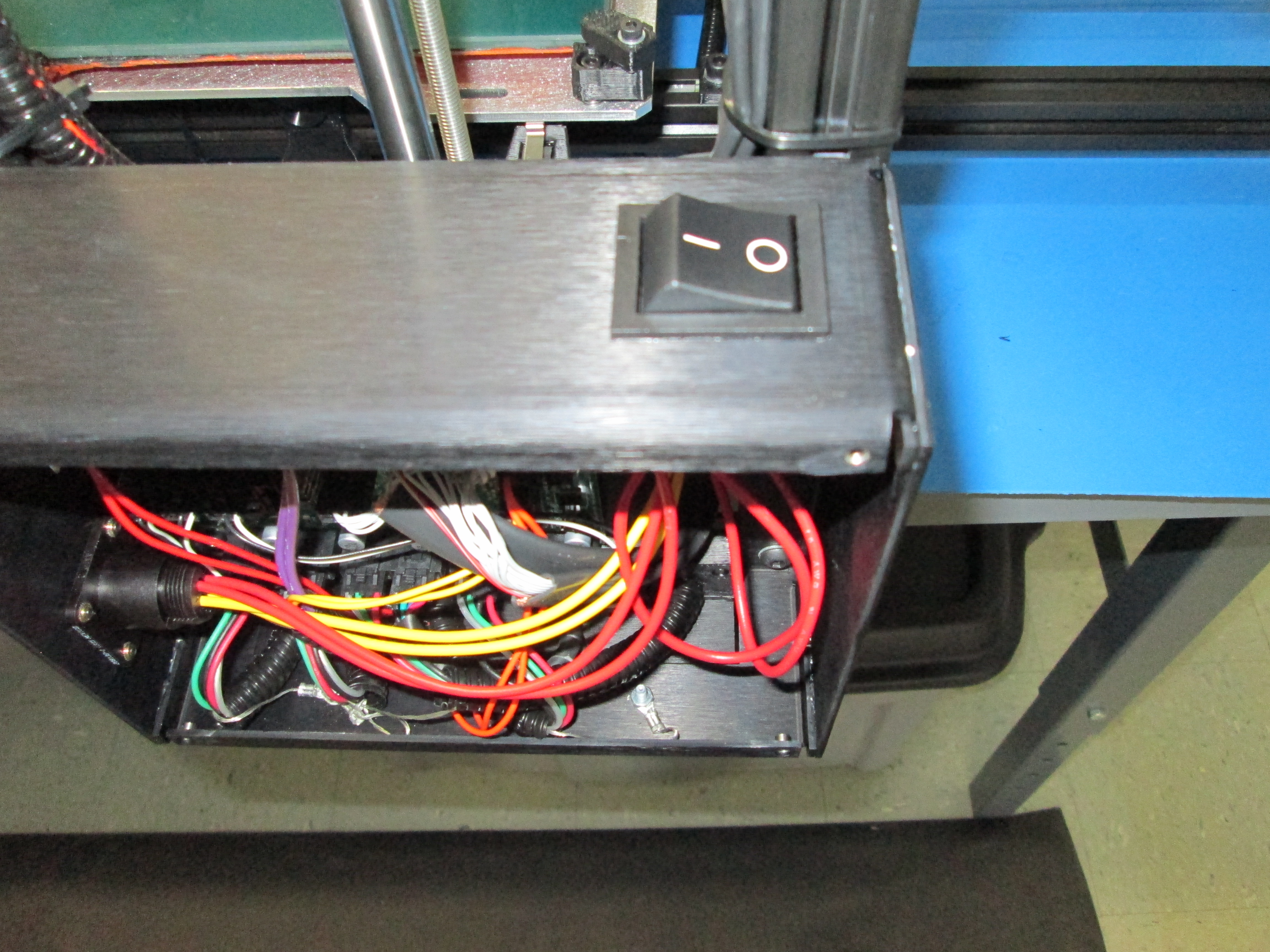
Snap the power switch into position on the electronics case. Note: Make sure the 'OFF' position of the switch is towards the front of the printer.
Make sure the switch is in the 'OFF' position.